EP3992551A1 - Control circuit, air conditioner, and control method - Google Patents
Control circuit, air conditioner, and control method Download PDFInfo
- Publication number
- EP3992551A1 EP3992551A1 EP20896008.8A EP20896008A EP3992551A1 EP 3992551 A1 EP3992551 A1 EP 3992551A1 EP 20896008 A EP20896008 A EP 20896008A EP 3992551 A1 EP3992551 A1 EP 3992551A1
- Authority
- EP
- European Patent Office
- Prior art keywords
- module
- control
- drive
- pressure detection
- circuit
- Prior art date
- Legal status (The legal status is an assumption and is not a legal conclusion. Google has not performed a legal analysis and makes no representation as to the accuracy of the status listed.)
- Granted
Links
Images

Classifications
-
- F—MECHANICAL ENGINEERING; LIGHTING; HEATING; WEAPONS; BLASTING
- F25—REFRIGERATION OR COOLING; COMBINED HEATING AND REFRIGERATION SYSTEMS; HEAT PUMP SYSTEMS; MANUFACTURE OR STORAGE OF ICE; LIQUEFACTION SOLIDIFICATION OF GASES
- F25B—REFRIGERATION MACHINES, PLANTS OR SYSTEMS; COMBINED HEATING AND REFRIGERATION SYSTEMS; HEAT PUMP SYSTEMS
- F25B49/00—Arrangement or mounting of control or safety devices
- F25B49/005—Arrangement or mounting of control or safety devices of safety devices
-
- F—MECHANICAL ENGINEERING; LIGHTING; HEATING; WEAPONS; BLASTING
- F04—POSITIVE - DISPLACEMENT MACHINES FOR LIQUIDS; PUMPS FOR LIQUIDS OR ELASTIC FLUIDS
- F04B—POSITIVE-DISPLACEMENT MACHINES FOR LIQUIDS; PUMPS
- F04B49/00—Control, e.g. of pump delivery, or pump pressure of, or safety measures for, machines, pumps, or pumping installations, not otherwise provided for, or of interest apart from, groups F04B1/00 - F04B47/00
- F04B49/02—Stopping, starting, unloading or idling control
- F04B49/022—Stopping, starting, unloading or idling control by means of pressure
-
- F—MECHANICAL ENGINEERING; LIGHTING; HEATING; WEAPONS; BLASTING
- F04—POSITIVE - DISPLACEMENT MACHINES FOR LIQUIDS; PUMPS FOR LIQUIDS OR ELASTIC FLUIDS
- F04B—POSITIVE-DISPLACEMENT MACHINES FOR LIQUIDS; PUMPS
- F04B49/00—Control, e.g. of pump delivery, or pump pressure of, or safety measures for, machines, pumps, or pumping installations, not otherwise provided for, or of interest apart from, groups F04B1/00 - F04B47/00
- F04B49/06—Control using electricity
-
- F—MECHANICAL ENGINEERING; LIGHTING; HEATING; WEAPONS; BLASTING
- F04—POSITIVE - DISPLACEMENT MACHINES FOR LIQUIDS; PUMPS FOR LIQUIDS OR ELASTIC FLUIDS
- F04B—POSITIVE-DISPLACEMENT MACHINES FOR LIQUIDS; PUMPS
- F04B49/00—Control, e.g. of pump delivery, or pump pressure of, or safety measures for, machines, pumps, or pumping installations, not otherwise provided for, or of interest apart from, groups F04B1/00 - F04B47/00
- F04B49/08—Regulating by delivery pressure
-
- F—MECHANICAL ENGINEERING; LIGHTING; HEATING; WEAPONS; BLASTING
- F04—POSITIVE - DISPLACEMENT MACHINES FOR LIQUIDS; PUMPS FOR LIQUIDS OR ELASTIC FLUIDS
- F04B—POSITIVE-DISPLACEMENT MACHINES FOR LIQUIDS; PUMPS
- F04B49/00—Control, e.g. of pump delivery, or pump pressure of, or safety measures for, machines, pumps, or pumping installations, not otherwise provided for, or of interest apart from, groups F04B1/00 - F04B47/00
- F04B49/10—Other safety measures
-
- F—MECHANICAL ENGINEERING; LIGHTING; HEATING; WEAPONS; BLASTING
- F25—REFRIGERATION OR COOLING; COMBINED HEATING AND REFRIGERATION SYSTEMS; HEAT PUMP SYSTEMS; MANUFACTURE OR STORAGE OF ICE; LIQUEFACTION SOLIDIFICATION OF GASES
- F25B—REFRIGERATION MACHINES, PLANTS OR SYSTEMS; COMBINED HEATING AND REFRIGERATION SYSTEMS; HEAT PUMP SYSTEMS
- F25B49/00—Arrangement or mounting of control or safety devices
- F25B49/02—Arrangement or mounting of control or safety devices for compression type machines, plants or systems
- F25B49/022—Compressor control arrangements
-
- F—MECHANICAL ENGINEERING; LIGHTING; HEATING; WEAPONS; BLASTING
- F04—POSITIVE - DISPLACEMENT MACHINES FOR LIQUIDS; PUMPS FOR LIQUIDS OR ELASTIC FLUIDS
- F04B—POSITIVE-DISPLACEMENT MACHINES FOR LIQUIDS; PUMPS
- F04B2205/00—Fluid parameters
- F04B2205/05—Pressure after the pump outlet
-
- F—MECHANICAL ENGINEERING; LIGHTING; HEATING; WEAPONS; BLASTING
- F04—POSITIVE - DISPLACEMENT MACHINES FOR LIQUIDS; PUMPS FOR LIQUIDS OR ELASTIC FLUIDS
- F04B—POSITIVE-DISPLACEMENT MACHINES FOR LIQUIDS; PUMPS
- F04B35/00—Piston pumps specially adapted for elastic fluids and characterised by the driving means to their working members, or by combination with, or adaptation to, specific driving engines or motors, not otherwise provided for
- F04B35/04—Piston pumps specially adapted for elastic fluids and characterised by the driving means to their working members, or by combination with, or adaptation to, specific driving engines or motors, not otherwise provided for the means being electric
-
- F—MECHANICAL ENGINEERING; LIGHTING; HEATING; WEAPONS; BLASTING
- F25—REFRIGERATION OR COOLING; COMBINED HEATING AND REFRIGERATION SYSTEMS; HEAT PUMP SYSTEMS; MANUFACTURE OR STORAGE OF ICE; LIQUEFACTION SOLIDIFICATION OF GASES
- F25B—REFRIGERATION MACHINES, PLANTS OR SYSTEMS; COMBINED HEATING AND REFRIGERATION SYSTEMS; HEAT PUMP SYSTEMS
- F25B2400/00—Component parts or details not otherwise provided for in this subclass
- F25B2400/07—Details of compressors or related parts
- F25B2400/077—Compressor control units, e.g. terminal boxes, mounted on the compressor casing wall containing for example starter, protection switches or connector contacts
-
- F—MECHANICAL ENGINEERING; LIGHTING; HEATING; WEAPONS; BLASTING
- F25—REFRIGERATION OR COOLING; COMBINED HEATING AND REFRIGERATION SYSTEMS; HEAT PUMP SYSTEMS; MANUFACTURE OR STORAGE OF ICE; LIQUEFACTION SOLIDIFICATION OF GASES
- F25B—REFRIGERATION MACHINES, PLANTS OR SYSTEMS; COMBINED HEATING AND REFRIGERATION SYSTEMS; HEAT PUMP SYSTEMS
- F25B2500/00—Problems to be solved
- F25B2500/07—Exceeding a certain pressure value in a refrigeration component or cycle
-
- F—MECHANICAL ENGINEERING; LIGHTING; HEATING; WEAPONS; BLASTING
- F25—REFRIGERATION OR COOLING; COMBINED HEATING AND REFRIGERATION SYSTEMS; HEAT PUMP SYSTEMS; MANUFACTURE OR STORAGE OF ICE; LIQUEFACTION SOLIDIFICATION OF GASES
- F25B—REFRIGERATION MACHINES, PLANTS OR SYSTEMS; COMBINED HEATING AND REFRIGERATION SYSTEMS; HEAT PUMP SYSTEMS
- F25B2600/00—Control issues
- F25B2600/02—Compressor control
- F25B2600/025—Compressor control by controlling speed
- F25B2600/0251—Compressor control by controlling speed with on-off operation
-
- F—MECHANICAL ENGINEERING; LIGHTING; HEATING; WEAPONS; BLASTING
- F25—REFRIGERATION OR COOLING; COMBINED HEATING AND REFRIGERATION SYSTEMS; HEAT PUMP SYSTEMS; MANUFACTURE OR STORAGE OF ICE; LIQUEFACTION SOLIDIFICATION OF GASES
- F25B—REFRIGERATION MACHINES, PLANTS OR SYSTEMS; COMBINED HEATING AND REFRIGERATION SYSTEMS; HEAT PUMP SYSTEMS
- F25B2600/00—Control issues
- F25B2600/02—Compressor control
- F25B2600/027—Compressor control by controlling pressure
Definitions
- the present disclosure relates to the compressor field, specifically to a control circuit, an air conditioner and a control method.
- a compressor and a pressure vessel are important parts for an air conditioner system.
- a system pressure is high, if no precautionary measures are taken for the compressor, to control the compressor to stop operation, it will cause the system pressure to continue rising, which is prone to danger.
- the pressure vessel is provided with a pressure relief valve.
- the pressure relief valve When a pressure in the pressure vessel exceeds a safety pressure, the pressure relief valve is opened to reduce the pressure in the pressure vessel.
- the pressure relief valve arranged at the pressure vessel is poor in sealing performance, leading to leakage easily.
- the present disclosure aims to solve at least one of the technical problems existing in the prior art or the related art.
- a first aspect of the present disclosure provides a control circuit.
- a second aspect of the present disclosure provides an air conditioner.
- a third aspect of the present disclosure provides a control method.
- the first aspect of the present disclosure provides a control circuit, including a drive module, a drive circuit, a first switch module, and a pressure detection module.
- the drive circuit is connected to the drive module.
- the first switch module is arranged at the drive circuit.
- the pressure detection module is connected to the first switch module and configured to control the first switch module to be connected or disconnected, and thus control the drive circuit to turn on or turn off.
- the control circuit controls the first switch assembly by the pressure detection module, and thus controls the drive module to stop operation, such that the pressure in the pressure vessel will not continue rising after the drive module stops operation.
- the drive circuit is controlled to turn on or turn off directly by the first switch assembly, thus reducing components involved in the control process to allow a simpler control circuit and a more rapid response, decreasing probability of control failure due to component damage, and improving reliability of the control circuit.
- control circuit in the above technical solution provided by the present disclosure may further have the following additional technical solutions.
- control circuit further includes a control module connected to the drive module.
- control module is connected to the drive module, and configured to control the drive module according to a status of the pressure detection module. Once a pressure detected by the pressure detection module exceeds a safety pressure, the drive module is controlled to stop operation, so as to avoid the drive module and the compressor from directly powering on when the pressure is returned to below the safety pressure and when the first switch assembly is connected, thus reducing impact on the drive module and the compressor when powered on, and prolonging service life of the drive module and the compressor.
- the drive circuit includes a first circuit and a second circuit;
- the first switch module includes a first input port, a first output port, a first control port, and a second control port; the first input port is connected to the first circuit; the first output port is connected to the second circuit; the first control port is connected to the pressure detection module; and the second control port is connected to the control module.
- control module outputs a high level to the second control port, such that the first switch assembly can be still controlled to be disconnected even if the contact of the pressure detection module is connected, thus avoiding the drive module and the compressor from directly powering on, reducing impact on the drive module and the compressor when powered on, and prolonging service life of the drive module and the compressor.
- the control circuit further includes a second switch module and a resistor;
- the second switch module includes a second input port, a second output port, a third control port and a fourth control port; the second output port is connected to the second circuit; the third control port is connected to the pressure detection module; the fourth control port is connected to the control module; and an end of the resistor is connected to the second input port; and another end of the resistor is connected to the first circuit.
- the second switch assembly when the drive module is powered on, the second switch assembly is controlled to be connected first; after the second switch assembly is connected, the first switch assembly is then connected, so as to reduce impact on the drive module and the compressor, and prolong service life of the drive module and the compressor.
- control circuit further includes a control power module, connected to the pressure detection module.
- control power module is configured to provide power to the first switch assembly and the second switch assembly, so that the control module controls the first switch assembly and the second switch assembly by changing an interface output signal.
- the drive circuit includes three wires; the first switch module includes at least two relays; and the at least two relays are arranged on at least two of the three wires.
- the drive circuit includes three wires, which are connected to a three-phase power, so as to drive and control a three-phase compressor.
- the drive circuit includes two wires; the first switch module includes at least one relay; and the at least one relay is arranged on at least one of the two wires.
- the drive circuit includes two wires, which are connected to a one-phase power, so as to drive and control a one-phase compressor.
- the second aspect of the present disclosure provides an air conditioner, including the control circuit as described in any above technical solution. Therefore, the air conditioner has all beneficial effects of the control circuit as described in any above technical solution.
- the air conditioner further includes an outdoor heat exchanger, an indoor heat exchanger, a compressor, and a throttle.
- the outdoor heat exchanger, the compressor, the indoor heat exchanger and the throttle are connected in sequence, and the pressure detection component is arranged at the outdoor heat exchanger and/or the indoor heat exchanger.
- the third aspect of the present disclosure provides a control method for the control circuit as described in any above technical solution.
- the control method includes: acquiring a status of a pressure detection module; and controlling a drive module and/or a first switch assembly according to the status of the pressure detection module.
- the control method provided by the present disclosure controls the first switch assembly by the pressure detection module, and thus controls the drive module to stop operation, such that the pressure in the pressure vessel will not continue rising after the drive module stops operation.
- the drive circuit is controlled to turn on or turn off directly by the first switch assembly, thus reducing components involved in the control process to allow a simpler control circuit and a more rapid response, decreasing probability of control failure due to component damage, and improving reliability of the control circuit.
- the drive module is controlled to stop operation, or the first switch assembly is controlled to be disconnected, so as to avoid the drive module and the compressor from directly powering on when the pressure is returned to below the safety pressure and when the first switch assembly is connected, thus reducing impact on the drive module and the compressor when powered on, and prolonging service life of the drive module and the compressor.
- controlling a drive module and/or a first switch assembly according to the status of the pressure detection module includes: controlling the drive module to stop operation and/or controlling the first switch assembly to be disconnected based on that the status of the pressure detection module is turned off; and controlling the drive module to start operation and/or controlling the first switch assembly to be connected based on that the status of the pressure detection module is turned on.
- control method further includes controlling a second switch assembly according to the status of the pressure detection module, after acquiring the status of the pressure detection module and before controlling the drive module and/or the first switch assembly according to the status of the pressure detection module.
- the second switch assembly when the drive module is powered on, the second switch assembly is connected first. After the second switch assembly is connected, the first switch assembly is then controlled to be connected, so as to reduce impact on the drive module and the compressor by the resistor, and prolong service life of the drive module and the compressor.
- the present disclosure provides a control circuit, including a drive module 102, a drive circuit 104, a first switch module 106 and a pressure detection module 108.
- the drive circuit 104 is connected to the drive module 102.
- the first switch module 106 is arranged at the drive circuit 104.
- the pressure detection module 108 is connected to the first switch module 106 and configured to control the first switch module 106 to be connected or disconnected, and thus control the drive circuit 104 to turn on or turn off.
- the first switch module 106 is arranged at the drive circuit 104; the pressure detection module 108 is configured to control the first switch assembly to be connected or disconnected.
- the pressure detection module 108 is turned off, a control port of the first switch assembly is powered off, the first switch assembly is disconnected, the drive circuit 104 is turned off, the drive module 102 is powered off, to make the drive module 102 stop operation, thus avoiding the pressure from further rising.
- the drive module 102 is controlled to stop operation by the pressure detection module 108, and accordingly the pressure in the pressure vessel will not continue rising after the drive module 102 stops operation.
- the drive circuit 104 is controlled to turn on or turn off directly by the first switch assembly, thus reducing components involved in the control process to allow a simpler control circuit and a more rapid response, decreasing probability of control failure due to component damage, and improving reliability of the control circuit.
- the drive module 102 is configured to drive a compressor 118.
- the drive module 102 is powered by a power supply via the drive circuit 104.
- the pressure detection module 108 is a pressure switch and configured to detect a pressure in a heat exchanger or a refrigerant pipe.
- the pressure detection module 108 When the pressure in the heat exchanger or the refrigerant pipe exceeds the safety pressure, the pressure detection module 108 is turned off; the control port of the first switch assembly is powered off, an input port and an output port of the first switch assembly are disconnected; the drive circuit 104 is turned off; the drive module 102 is powered off; and the compressor 118 is stopped being driven to stop operation, such that the pressure in the heat exchanger or the refrigerant pipe does not continue rising, thereby avoiding dangers caused by overpressure in a refrigerating or heating device, such as an air conditioner, a water heater and a refrigerator, and a heat exchanger, guaranteeing normal operation of the device.
- a refrigerating or heating device such as an air conditioner, a water heater and a refrigerator, and a heat exchanger, guaranteeing normal operation of the device.
- the first switch assembly is a normally open switch. When it is detected by the pressure detection module 108 that the pressure in the heat exchanger or the refrigerant pipe exceeds the safety pressure, the contact of the pressure detection module 108 is disconnected, such that the first switch assembly is powered off; the input port and the output port of the first switch assembly are disconnected; the drive circuit 104 is turned off; the drive module 102 is powered off; and the compressor 118 is stopped being driven to stop operation, thus the pressure in the heat exchanger or the refrigerant pipe does not continue rising.
- the first switch component is a normally closed switch.
- the contact of the pressure detection module 108 is connected, such that the first switch assembly is powered on; the input port and the output port of the first switch assembly are disconnected; the drive circuit 104 is turned off; the drive module 102 is powered off; and the compressor 118 is stopped being driven to stop operation, thus the pressure in the heat exchanger or the refrigerant pipe does not continue rising.
- the heat exchanger exchanges heat with air, and a temperature and a pressure of the refrigerant in the heat exchanger are reduced.
- control circuit further includes a control module 110 connected to the drive module 102.
- control module 110 is connected to the drive module 102, and is configured to control the drive module 102 according to a status of the pressure detection module 108. Once the pressure detected by the pressure detection module 108 exceeds the safety pressure, the drive module 102 is controlled to stop operation, so as to avoid the drive module 102 and the compressor 118 from directly powering on when the pressure is returned to below the safety pressure and when the first switch assembly is connected, thus reducing impact on the drive module 102 and the compressor 118 when powered on, and prolonging service life of the drive module 102 and the compressor 118.
- the control module 110 is configured to detect the status of the pressure detection module 108, or receive status information from the pressure detection module 108, and thus control the drive module 102 according to the status of the pressure detection module 108.
- the drive circuit 104 includes a first circuit 1042 and a second circuit 1044;
- the first switch module 106 includes a first input port 1062, a first output port 1064, a first control port 1066, and a second control port 1068, wherein the first input port 1062 is connected to the first circuit 1042, the first output port 1064 is connected to the second circuit 1044, the first control port 1066 is connected to the pressure detection module 108, and the second control port 1068 is connected to the control module 110.
- the first control port 1066 and the second control port 1068 are powered on or powered off, to control the first input port 1062 and the first output port 1064 to be connected or disconnected.
- the first control port 1066 is connected to the pressure detection module 108, when the contact of the pressure detection module 108 is disconnected, the first control port 1066 is powered off; while when the contact of the pressure detection module 108 is connected, the first control port 1066 is powered on.
- the second control port 1068 is connected to the control module 110, when the first control port 1066 is provided with a high level, and when the control module 110 outputs a low level, the first control port 1066 and the second control port 1068 are powered on; when the control module 110 outputs a high level, the first control port 1066 and the second control port 1068 are powered off, such that the control module 110 can control the first switch assembly to be connected or disconnected.
- the control module 110 When the first switch assembly is disconnected, the control module 110 outputs a high level to the second control port 1068, such that the first switch assembly can be still controlled to be disconnected even if the contact of the pressure detection module 108 is connected, thus avoiding the drive module 102 and the compressor 118 from directly powering on, reducing impact on the drive module 102 and the compressor 118 when powered on, and prolonging service life of the drive module 102 and the compressor 118.
- the control circuit further includes a second switch module 112 and a resistor 114.
- the second switch module 112 includes a second input port, a second output port, and a third control port and a fourth control port.
- the second output port is connected to the second circuit 1044.
- the third control port is connected to the pressure detection module 108.
- the fourth control port is connected to the control module 110.
- An end of the resistor 114 is connected to the second input port, and another end of the resistor 114 is connected to the first circuit 1042.
- the second switch assembly when the drive module 102 is powered on, the second switch assembly is connected first. After the second switch assembly is connected, the first switch assembly is then controlled to be connected, so as to reduce impact on the drive module 102 and the compressor 118 by the resistor 114, and prolong service life of the drive module 102 and the compressor 118.
- the second switch assembly is a relay.
- control circuit further includes a control power module 116.
- the control power module 116 is connected to the pressure detection module 108.
- control power module 116 is configured to provide power to the first switch assembly and the second switch assembly, so that the control module 110 controls the first switch assembly and the second switch assembly by changing an interface output signal.
- the power module outputs a positive 12V voltage or a positive 24V voltage to the pressure detection module 108, and outputs a positive 3.3V voltage to the control module 110.
- the drive circuit 104 includes three wires; the first switch module 106 includes two relays; and the two relays are arranged at two of the three wires, respectively.
- the drive circuit 104 includes three wires; the first switch module 106 includes three relays; and the three relays are arranged at the three wires, respectively.
- the drive circuit 104 includes three wires; the first switch module 106 includes one two-way relay; and the two-way relay is arranged at two of the three wires.
- the drive circuit 104 includes three wires; the first switch module 106 includes one three-way relay; and the three-way relay is arranged at the three wires.
- the drive circuit 104 includes three wires, which are connected to a three-phase power, so as to drive and control a three-phase compressor 118.
- the drive circuit 104 includes two wires; the first switch module 106 includes one one-way relay; and the one-way relay is arranged at one of the two wires.
- the drive circuit 104 includes two wires; the first switch module 106 includes two one-way relays; and the two one-way relays are arranged at the two wires, respectively.
- the drive circuit 104 includes two wires; the first switch module 106 includes one two-way relay; and the two-way relay is arranged at the two wires.
- the drive circuit 104 includes two wires, which are connected to a one-phase power, so as to drive and control a one-phase compressor 118.
- the present disclosure provides an air conditioner, including the control circuit as described in any above embodiment. Therefore, the air conditioner has all beneficial effects of the control circuit as described in any above embodiment.
- the air conditioner further includes an outdoor heat exchanger, an indoor heat exchanger, a compressor and a throttle.
- the outdoor heat exchanger, the compressor, the indoor heat exchanger and the throttle are connected in sequence, and the pressure detection component is arranged at the outdoor heat exchanger and/or the indoor heat exchanger.
- the present disclosure provides a control method for the control circuit as described in any above embodiment. As shown in Figure 4 , the control method includes steps 402 and 404.
- a status of a pressure detection module is acquired.
- a drive module and/or a first switch assembly are(is) controlled according to the status of the pressure detection module.
- the drive module is controlled to stop operation by the pressure detection module, the pressure in the pressure vessel will not continue rising once the drive module stops operation.
- a pressure relief valve for prevention of overpressure, thus improving sealing performance of the pressure vessel and reducing leakage of refrigerant media.
- the drive circuit is controlled to turn on or turn off directly by the first switch assembly, thus reducing components involved in the control process to allow a simpler control circuit and a more rapid response, decreasing probability of control failure due to component damage, and improving reliability of the control circuit.
- the drive module is controlled to stop operation, or the first switch assembly is controlled to be disconnected, so as to avoid the drive module and the compressor from directly powering on when the pressure is returned to below the safety pressure and when the first switch assembly is connected, thus reducing impact on the drive module and the compressor when powered on, and prolonging service life of the drive module and the compressor.
- control method includes steps 502 and 504.
- a status of a pressure detection module is acquired.
- the drive module is controlled to stop operation based on that the status of the pressure detection module is turned off.
- control method includes steps 602 and 604.
- a status of a pressure detection module is acquired.
- the first switch assembly is controlled to be disconnected based on that the status of the pressure detection module is turned off.
- control method includes steps 702 and 704.
- a status of a pressure detection module is acquired.
- the drive module is controlled to start operation based on that the status of the pressure detection module is turned on.
- control method includes steps 802 and 804.
- a status of a pressure detection module is acquired.
- the first switch assembly is controlled to be connected based on that the status of the pressure detection module is turned on.
- the drive module when the status of the pressure detection module is detected to be turned off, it is indicated that the pressure detected by the pressure switch exceeds the safety pressure, then the drive module is controlled to stop operation, and/or the first switch assembly is controlled to be disconnected; when the status of the pressure detection module is detected to be turned on, it is indicated that the pressure detected by the pressure switch is below the safety pressure, then the drive module is controlled to start operation, and/or the first switch assembly is controlled to be connected, so as to drive the compressor to continue operation.
- control method includes steps 902, 904 and 906.
- a status of a pressure detection module is acquired.
- a second switch assembly is controlled according to the status of the pressure detection module.
- the drive module and/or the first switch assembly are(is) controlled according to the status of the pressure detection module.
- the second switch assembly when the drive module is powered on, the second switch assembly is connected first. After the second switch assembly is connected, the first switch assembly is then controlled to be connected, so as to reduce impact on the drive module and the compressor by the resistor, and prolong service life of the drive module and the compressor.
- Controlling a second switch assembly according to the status of the pressure detection module includes: controlling the second switch assembly to be disconnected based on that the status of the pressure detection module is turned off; and controlling the second switch assembly to be connected based on that the status of the pressure detection module is turned on.
- control method includes:
- connection means, for example, fixed connections, detachable connections, or integrated connections; may also be direct connections or indirect connections via intervening structures, which can be understood by those ordinary skilled in the art according to specific situations.
Landscapes
- Engineering & Computer Science (AREA)
- Mechanical Engineering (AREA)
- General Engineering & Computer Science (AREA)
- Physics & Mathematics (AREA)
- Thermal Sciences (AREA)
- Air Conditioning Control Device (AREA)
Abstract
Description
- This application claims priority to and the benefit of the
Chinese Patent Application No. "201911211248.1" filed on December 02, 2019 - The present disclosure relates to the compressor field, specifically to a control circuit, an air conditioner and a control method.
- At present, a compressor and a pressure vessel are important parts for an air conditioner system. In a system containing a compressor and a pressure vessel, when a system pressure is high, if no precautionary measures are taken for the compressor, to control the compressor to stop operation, it will cause the system pressure to continue rising, which is prone to danger.
- In the related art, the pressure vessel is provided with a pressure relief valve. When a pressure in the pressure vessel exceeds a safety pressure, the pressure relief valve is opened to reduce the pressure in the pressure vessel. However, the pressure relief valve arranged at the pressure vessel is poor in sealing performance, leading to leakage easily.
- The present disclosure aims to solve at least one of the technical problems existing in the prior art or the related art.
- For this, a first aspect of the present disclosure provides a control circuit.
- A second aspect of the present disclosure provides an air conditioner.
- A third aspect of the present disclosure provides a control method.
- In view of this, the first aspect of the present disclosure provides a control circuit, including a drive module, a drive circuit, a first switch module, and a pressure detection module. The drive circuit is connected to the drive module. The first switch module is arranged at the drive circuit. The pressure detection module is connected to the first switch module and configured to control the first switch module to be connected or disconnected, and thus control the drive circuit to turn on or turn off.
- The control circuit provided by the present disclosure controls the first switch assembly by the pressure detection module, and thus controls the drive module to stop operation, such that the pressure in the pressure vessel will not continue rising after the drive module stops operation. As a result, it is not necessary to additionally arrange a pressure relief valve for prevention of overpressure, thus improving sealing performance of the pressure vessel and reducing leakage of refrigerant media. The drive circuit is controlled to turn on or turn off directly by the first switch assembly, thus reducing components involved in the control process to allow a simpler control circuit and a more rapid response, decreasing probability of control failure due to component damage, and improving reliability of the control circuit.
- In addition, the control circuit in the above technical solution provided by the present disclosure may further have the following additional technical solutions.
- In an example of the present disclosure, the control circuit further includes a control module connected to the drive module.
- In this technical solution, the control module is connected to the drive module, and configured to control the drive module according to a status of the pressure detection module. Once a pressure detected by the pressure detection module exceeds a safety pressure, the drive module is controlled to stop operation, so as to avoid the drive module and the compressor from directly powering on when the pressure is returned to below the safety pressure and when the first switch assembly is connected, thus reducing impact on the drive module and the compressor when powered on, and prolonging service life of the drive module and the compressor.
- According to an example of the present disclosure, the drive circuit includes a first circuit and a second circuit; the first switch module includes a first input port, a first output port, a first control port, and a second control port; the first input port is connected to the first circuit; the first output port is connected to the second circuit; the first control port is connected to the pressure detection module; and the second control port is connected to the control module.
- In this technical solution, the control module outputs a high level to the second control port, such that the first switch assembly can be still controlled to be disconnected even if the contact of the pressure detection module is connected, thus avoiding the drive module and the compressor from directly powering on, reducing impact on the drive module and the compressor when powered on, and prolonging service life of the drive module and the compressor.
- According to an example of the present disclosure, the control circuit further includes a second switch module and a resistor; the second switch module includes a second input port, a second output port, a third control port and a fourth control port; the second output port is connected to the second circuit; the third control port is connected to the pressure detection module; the fourth control port is connected to the control module; and an end of the resistor is connected to the second input port; and another end of the resistor is connected to the first circuit.
- In this technical solution, by arranging the second switch assembly and the resistor, when the drive module is powered on, the second switch assembly is controlled to be connected first; after the second switch assembly is connected, the first switch assembly is then connected, so as to reduce impact on the drive module and the compressor, and prolong service life of the drive module and the compressor.
- According to an example of the present disclosure, the control circuit further includes a control power module, connected to the pressure detection module.
- In this technical solution, the control power module is configured to provide power to the first switch assembly and the second switch assembly, so that the control module controls the first switch assembly and the second switch assembly by changing an interface output signal.
- According to an example of the present disclosure, the drive circuit includes three wires; the first switch module includes at least two relays; and the at least two relays are arranged on at least two of the three wires.
- In this technical solution, the drive circuit includes three wires, which are connected to a three-phase power, so as to drive and control a three-phase compressor.
- According to an example of the present disclosure, the drive circuit includes two wires; the first switch module includes at least one relay; and the at least one relay is arranged on at least one of the two wires.
- In this technical solution, the drive circuit includes two wires, which are connected to a one-phase power, so as to drive and control a one-phase compressor.
- The second aspect of the present disclosure provides an air conditioner, including the control circuit as described in any above technical solution. Therefore, the air conditioner has all beneficial effects of the control circuit as described in any above technical solution.
- The air conditioner further includes an outdoor heat exchanger, an indoor heat exchanger, a compressor, and a throttle. The outdoor heat exchanger, the compressor, the indoor heat exchanger and the throttle are connected in sequence, and the pressure detection component is arranged at the outdoor heat exchanger and/or the indoor heat exchanger.
- The third aspect of the present disclosure provides a control method for the control circuit as described in any above technical solution. The control method includes: acquiring a status of a pressure detection module; and controlling a drive module and/or a first switch assembly according to the status of the pressure detection module.
- The control method provided by the present disclosure controls the first switch assembly by the pressure detection module, and thus controls the drive module to stop operation, such that the pressure in the pressure vessel will not continue rising after the drive module stops operation. As a result, it is not necessary to additionally arrange a pressure relief valve for prevention of overpressure, thus improving sealing performance of the pressure vessel and reducing leakage of refrigerant media. The drive circuit is controlled to turn on or turn off directly by the first switch assembly, thus reducing components involved in the control process to allow a simpler control circuit and a more rapid response, decreasing probability of control failure due to component damage, and improving reliability of the control circuit.
- Once the pressure detected exceeds the safety pressure, the drive module is controlled to stop operation, or the first switch assembly is controlled to be disconnected, so as to avoid the drive module and the compressor from directly powering on when the pressure is returned to below the safety pressure and when the first switch assembly is connected, thus reducing impact on the drive module and the compressor when powered on, and prolonging service life of the drive module and the compressor.
- According to an example of the present disclosure, controlling a drive module and/or a first switch assembly according to the status of the pressure detection module includes: controlling the drive module to stop operation and/or controlling the first switch assembly to be disconnected based on that the status of the pressure detection module is turned off; and controlling the drive module to start operation and/or controlling the first switch assembly to be connected based on that the status of the pressure detection module is turned on.
- In this technical solution, when the status of the pressure detection module is detected to be turned off, it is indicated that the pressure detected by the pressure switch exceeds the safety pressure, then the drive module is controlled to stop operation, and/or the first switch assembly is controlled to be disconnected; when the status of the pressure detection module is detected to be turned on, it is indicated that the pressure detected by the pressure switch is below the safety pressure, then the drive module is controlled to start operation, and/or the first switch assembly is controlled to be connected, so as to drive the compressor to continue operation.
- According to an example of the present disclosure, the control method further includes controlling a second switch assembly according to the status of the pressure detection module, after acquiring the status of the pressure detection module and before controlling the drive module and/or the first switch assembly according to the status of the pressure detection module.
- In this technical solution, when the drive module is powered on, the second switch assembly is connected first. After the second switch assembly is connected, the first switch assembly is then controlled to be connected, so as to reduce impact on the drive module and the compressor by the resistor, and prolong service life of the drive module and the compressor.
- The additional aspects and advantages of the present disclosure will be partially given in the following description, and some will become obvious from the following description, or be understood through the practice of the present disclosure.
- The above and/or additional aspects and advantages of the present disclosure will become apparent and easily understood from the description of the embodiment in connection with the following drawings.
-
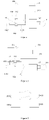
Figure 1 is a schematic diagram showing a control circuit according to an embodiment of the present disclosure. -
Figure 2 is a schematic diagram showing a control circuit according to another embodiment of the present disclosure. -
Figure 3 is a schematic diagram showing a first switch assembly according to an embodiment of the present disclosure. -
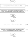
Figure 4 is a flow chart showing a control method according to an embodiment of the present disclosure. -
Figure 5 is a flow chart showing a control method according to another embodiment of the present disclosure. -
Figure 6 is a flow chart showing a control method according to still another embodiment of the present disclosure. -
Figure 7 is a flow chart showing a control method according to yet another embodiment of the present disclosure. -
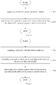
Figure 8 is a flow chart showing a control method according to yet another embodiment of the present disclosure. -
Figure 9 is a flow chart showing a control method according to yet another embodiment of the present disclosure. - 102 drive module; 104 drive circuit; 1042 first circuit; 1044 second circuit; 106 first switch module; 1062 first input port; 1064 first output port; 1066 first control port; 1068 second control port; 108 pressure detection module; 110 control module; 112 second switch module; 114 resistor; 116 control power module; and 118 compressor.
- In order to understand the above objects, features and advantages of the present disclosure, the following detailed description will be made in conjunction with the accompanying drawings and embodiments. It should be noted that different embodiments and features in different embodiments of the present disclosure can be combined with each other without conflict.
- Many specific details are set forth in the following description to fully understand the present disclosure. However, the present disclosure can be implemented by other ways different from those described herein. Therefore, the protection scope of the present disclosure is not limited to the specific embodiments disclosed below.
- Reference is made to a control circuit, an air conditioner and a control method according to some embodiments in conjunction with
Figure 1 to Figure 9 . - In an embodiment of the first aspect of the present disclosure, as shown in
Figure 1 and Figure 2 , the present disclosure provides a control circuit, including adrive module 102, adrive circuit 104, afirst switch module 106 and apressure detection module 108. Thedrive circuit 104 is connected to thedrive module 102. Thefirst switch module 106 is arranged at thedrive circuit 104. Thepressure detection module 108 is connected to thefirst switch module 106 and configured to control thefirst switch module 106 to be connected or disconnected, and thus control thedrive circuit 104 to turn on or turn off. - In this embodiment, the
first switch module 106 is arranged at thedrive circuit 104; thepressure detection module 108 is configured to control the first switch assembly to be connected or disconnected. When a pressure detected by thepressure detection module 108 exceeds a safety pressure, thepressure detection module 108 is turned off, a control port of the first switch assembly is powered off, the first switch assembly is disconnected, thedrive circuit 104 is turned off, thedrive module 102 is powered off, to make thedrive module 102 stop operation, thus avoiding the pressure from further rising. As thedrive module 102 is controlled to stop operation by thepressure detection module 108, and accordingly the pressure in the pressure vessel will not continue rising after thedrive module 102 stops operation. As a result, it is not necessary to additionally arrange a pressure relief valve for prevention of overpressure, thus improving sealing performance of the pressure vessel and reducing leakage of refrigerant media. Thedrive circuit 104 is controlled to turn on or turn off directly by the first switch assembly, thus reducing components involved in the control process to allow a simpler control circuit and a more rapid response, decreasing probability of control failure due to component damage, and improving reliability of the control circuit. - The
drive module 102 is configured to drive acompressor 118. Thedrive module 102 is powered by a power supply via thedrive circuit 104. Thepressure detection module 108 is a pressure switch and configured to detect a pressure in a heat exchanger or a refrigerant pipe. When the pressure in the heat exchanger or the refrigerant pipe exceeds the safety pressure, thepressure detection module 108 is turned off; the control port of the first switch assembly is powered off, an input port and an output port of the first switch assembly are disconnected; thedrive circuit 104 is turned off; thedrive module 102 is powered off; and thecompressor 118 is stopped being driven to stop operation, such that the pressure in the heat exchanger or the refrigerant pipe does not continue rising, thereby avoiding dangers caused by overpressure in a refrigerating or heating device, such as an air conditioner, a water heater and a refrigerator, and a heat exchanger, guaranteeing normal operation of the device. - The first switch assembly is a normally open switch. When it is detected by the
pressure detection module 108 that the pressure in the heat exchanger or the refrigerant pipe exceeds the safety pressure, the contact of thepressure detection module 108 is disconnected, such that the first switch assembly is powered off; the input port and the output port of the first switch assembly are disconnected; thedrive circuit 104 is turned off; thedrive module 102 is powered off; and thecompressor 118 is stopped being driven to stop operation, thus the pressure in the heat exchanger or the refrigerant pipe does not continue rising. - The first switch component is a normally closed switch. When it is detected by the
pressure detection module 108 that the pressure in the heat exchanger or the refrigerant pipe exceeds the safety pressure, the contact of thepressure detection module 108 is connected, such that the first switch assembly is powered on; the input port and the output port of the first switch assembly are disconnected; thedrive circuit 104 is turned off; thedrive module 102 is powered off; and thecompressor 118 is stopped being driven to stop operation, thus the pressure in the heat exchanger or the refrigerant pipe does not continue rising. - After the
compressor 118 stops operation, the heat exchanger exchanges heat with air, and a temperature and a pressure of the refrigerant in the heat exchanger are reduced. - In an embodiment of the present disclosure, as shown in
Figure 1 and Figure 2 , the control circuit further includes acontrol module 110 connected to thedrive module 102. - In this embodiment, the
control module 110 is connected to thedrive module 102, and is configured to control thedrive module 102 according to a status of thepressure detection module 108. Once the pressure detected by thepressure detection module 108 exceeds the safety pressure, thedrive module 102 is controlled to stop operation, so as to avoid thedrive module 102 and thecompressor 118 from directly powering on when the pressure is returned to below the safety pressure and when the first switch assembly is connected, thus reducing impact on thedrive module 102 and thecompressor 118 when powered on, and prolonging service life of thedrive module 102 and thecompressor 118. - The
control module 110 is configured to detect the status of thepressure detection module 108, or receive status information from thepressure detection module 108, and thus control thedrive module 102 according to the status of thepressure detection module 108. - In an embodiment of the present disclosure, as shown in
Figure 1 to Figure 3 , thedrive circuit 104 includes afirst circuit 1042 and asecond circuit 1044; thefirst switch module 106 includes afirst input port 1062, afirst output port 1064, afirst control port 1066, and asecond control port 1068, wherein thefirst input port 1062 is connected to thefirst circuit 1042, thefirst output port 1064 is connected to thesecond circuit 1044, thefirst control port 1066 is connected to thepressure detection module 108, and thesecond control port 1068 is connected to thecontrol module 110. - In this embodiment, the
first control port 1066 and thesecond control port 1068 are powered on or powered off, to control thefirst input port 1062 and thefirst output port 1064 to be connected or disconnected. Thefirst control port 1066 is connected to thepressure detection module 108, when the contact of thepressure detection module 108 is disconnected, thefirst control port 1066 is powered off; while when the contact of thepressure detection module 108 is connected, thefirst control port 1066 is powered on. Thesecond control port 1068 is connected to thecontrol module 110, when thefirst control port 1066 is provided with a high level, and when thecontrol module 110 outputs a low level, thefirst control port 1066 and thesecond control port 1068 are powered on; when thecontrol module 110 outputs a high level, thefirst control port 1066 and thesecond control port 1068 are powered off, such that thecontrol module 110 can control the first switch assembly to be connected or disconnected. When the first switch assembly is disconnected, thecontrol module 110 outputs a high level to thesecond control port 1068, such that the first switch assembly can be still controlled to be disconnected even if the contact of thepressure detection module 108 is connected, thus avoiding thedrive module 102 and thecompressor 118 from directly powering on, reducing impact on thedrive module 102 and thecompressor 118 when powered on, and prolonging service life of thedrive module 102 and thecompressor 118. - In an embodiment of the present disclosure, as shown in
Figure 1 and Figure 2 , the control circuit further includes asecond switch module 112 and aresistor 114. Thesecond switch module 112 includes a second input port, a second output port, and a third control port and a fourth control port. The second output port is connected to thesecond circuit 1044. The third control port is connected to thepressure detection module 108. The fourth control port is connected to thecontrol module 110. An end of theresistor 114 is connected to the second input port, and another end of theresistor 114 is connected to thefirst circuit 1042. - In this embodiment, by arranging the second switch assembly and the
resistor 114, when thedrive module 102 is powered on, the second switch assembly is connected first. After the second switch assembly is connected, the first switch assembly is then controlled to be connected, so as to reduce impact on thedrive module 102 and thecompressor 118 by theresistor 114, and prolong service life of thedrive module 102 and thecompressor 118. - The second switch assembly is a relay.
- In an embodiment of the present disclosure, as shown in
Figure 1 and Figure 2 , the control circuit further includes acontrol power module 116. Thecontrol power module 116 is connected to thepressure detection module 108. - In this embodiment, the
control power module 116 is configured to provide power to the first switch assembly and the second switch assembly, so that thecontrol module 110 controls the first switch assembly and the second switch assembly by changing an interface output signal. - The power module outputs a positive 12V voltage or a positive 24V voltage to the
pressure detection module 108, and outputs a positive 3.3V voltage to thecontrol module 110. - In an embodiment of the present disclosure, as shown in
Figure 1 , thedrive circuit 104 includes three wires; thefirst switch module 106 includes two relays; and the two relays are arranged at two of the three wires, respectively. - In an embodiment of the present disclosure, the
drive circuit 104 includes three wires; thefirst switch module 106 includes three relays; and the three relays are arranged at the three wires, respectively. - In an embodiment of the present disclosure, the
drive circuit 104 includes three wires; thefirst switch module 106 includes one two-way relay; and the two-way relay is arranged at two of the three wires. - In an embodiment of the present disclosure, the
drive circuit 104 includes three wires; thefirst switch module 106 includes one three-way relay; and the three-way relay is arranged at the three wires. - In this embodiment, the
drive circuit 104 includes three wires, which are connected to a three-phase power, so as to drive and control a three-phase compressor 118. - In an embodiment of the present disclosure, as shown in
Figure 2 , thedrive circuit 104 includes two wires; thefirst switch module 106 includes one one-way relay; and the one-way relay is arranged at one of the two wires. - In an embodiment of the present disclosure, the
drive circuit 104 includes two wires; thefirst switch module 106 includes two one-way relays; and the two one-way relays are arranged at the two wires, respectively. - In an embodiment of the present disclosure, the
drive circuit 104 includes two wires; thefirst switch module 106 includes one two-way relay; and the two-way relay is arranged at the two wires. - In this embodiment, the
drive circuit 104 includes two wires, which are connected to a one-phase power, so as to drive and control a one-phase compressor 118. - In an embodiment of the second aspect of the present disclosure, the present disclosure provides an air conditioner, including the control circuit as described in any above embodiment. Therefore, the air conditioner has all beneficial effects of the control circuit as described in any above embodiment.
- The air conditioner further includes an outdoor heat exchanger, an indoor heat exchanger, a compressor and a throttle. The outdoor heat exchanger, the compressor, the indoor heat exchanger and the throttle are connected in sequence, and the pressure detection component is arranged at the outdoor heat exchanger and/or the indoor heat exchanger.
- In an embodiment of the third aspect of the present disclosure, the present disclosure provides a control method for the control circuit as described in any above embodiment. As shown in
Figure 4 , the control method includessteps - At the
step 402, a status of a pressure detection module is acquired. - At the
step 404, a drive module and/or a first switch assembly are(is) controlled according to the status of the pressure detection module. - In this embodiment, as the drive module is controlled to stop operation by the pressure detection module, the pressure in the pressure vessel will not continue rising once the drive module stops operation. As a result, it is not necessary to additionally arrange a pressure relief valve for prevention of overpressure, thus improving sealing performance of the pressure vessel and reducing leakage of refrigerant media. The drive circuit is controlled to turn on or turn off directly by the first switch assembly, thus reducing components involved in the control process to allow a simpler control circuit and a more rapid response, decreasing probability of control failure due to component damage, and improving reliability of the control circuit.
- Once a pressure detected exceeds a safety pressure, the drive module is controlled to stop operation, or the first switch assembly is controlled to be disconnected, so as to avoid the drive module and the compressor from directly powering on when the pressure is returned to below the safety pressure and when the first switch assembly is connected, thus reducing impact on the drive module and the compressor when powered on, and prolonging service life of the drive module and the compressor.
- In an embodiment of the present disclosure, as shown in
Figure 5 , the control method includessteps - At the
step 502, a status of a pressure detection module is acquired. - At the
step 504, the drive module is controlled to stop operation based on that the status of the pressure detection module is turned off. - In an embodiment of the present disclosure, as shown in
Figure 6 , the control method includessteps - At the
step 602, a status of a pressure detection module is acquired. - At the
step 604, the first switch assembly is controlled to be disconnected based on that the status of the pressure detection module is turned off. - In an embodiment of the present disclosure, as shown in
Figure 7 , the control method includessteps - At the
step 702, a status of a pressure detection module is acquired. - At the
step 704, the drive module is controlled to start operation based on that the status of the pressure detection module is turned on. - In an embodiment of the present disclosure, as shown in
Figure 8 , the control method includessteps - At the
step 802, a status of a pressure detection module is acquired. - At the
step 804, the first switch assembly is controlled to be connected based on that the status of the pressure detection module is turned on. - In this embodiment, when the status of the pressure detection module is detected to be turned off, it is indicated that the pressure detected by the pressure switch exceeds the safety pressure, then the drive module is controlled to stop operation, and/or the first switch assembly is controlled to be disconnected; when the status of the pressure detection module is detected to be turned on, it is indicated that the pressure detected by the pressure switch is below the safety pressure, then the drive module is controlled to start operation, and/or the first switch assembly is controlled to be connected, so as to drive the compressor to continue operation.
- In an embodiment of the present disclosure, as shown in
Figure 9 , the control method includessteps - At the
step 902, a status of a pressure detection module is acquired. - At the
step 904, a second switch assembly is controlled according to the status of the pressure detection module. - At the step 906, the drive module and/or the first switch assembly are(is) controlled according to the status of the pressure detection module.
- In this embodiment, when the drive module is powered on, the second switch assembly is connected first. After the second switch assembly is connected, the first switch assembly is then controlled to be connected, so as to reduce impact on the drive module and the compressor by the resistor, and prolong service life of the drive module and the compressor.
- Controlling a second switch assembly according to the status of the pressure detection module includes: controlling the second switch assembly to be disconnected based on that the status of the pressure detection module is turned off; and controlling the second switch assembly to be connected based on that the status of the pressure detection module is turned on.
- In an embodiment of the present disclosure, the control method includes:
- acquiring a status of a pressure detection module;
- controlling a second switch assembly to be connected based on that the status of the pressure detection module is turned on;
- controlling the drive module to start operation and controlling the first switch assembly to be connected.
- In the description of the present disclosure, "a plurality of' means two or more than two this features, unless specified otherwise. The terms indicating orientation or position relationship such as "above" and "below" should be construed to refer to the orientation or position relationship as described or as shown in the drawings. These terms are merely for convenience and concision of description and do not alone indicate or imply that the device or element referred to must have a particular orientation or must be configured or operated in a particular orientation. Thus, it cannot be understood to limit the present disclosure. The terms "connected", "mounted" and "fixed" and the like are used broadly, and may be, for example, fixed connections, detachable connections, or integrated connections; may also be direct connections or indirect connections via intervening structures, which can be understood by those ordinary skilled in the art according to specific situations.
- Reference throughout this specification to "an embodiment/example", "some embodiments/examples" or "a specific example" means that a particular feature, structure, material, or characteristic described in connection with the embodiment or example is included in at least one embodiment or example of the present disclosure. Thus, the appearances of the phrases such as "an embodiment/example", "some embodiments/examples" or "a specific example" in various places throughout this specification are not necessarily referring to the same embodiment or example of the present disclosure. Furthermore, the particular features, structures, materials, or characteristics may be combined in any suitable manner in one or more embodiments or examples.
- The foregoing descriptions are only preferred embodiment of the present disclosure, but in no way to limit present disclosure. For those skilled in the art, the present disclosure may have various modifications and changes. Any modification, equivalent replacement, improvement, etc. made within the spirit and principles of the present disclosure shall be included in the protection scope of the present disclosure.
Claims (11)
- A control circuit, comprising:a drive module;a drive circuit, connected to the drive module;a first switch module, arranged at the drive circuit; anda pressure detection module, connected to the first switch module and configured to control the first switch module to be connected or disconnected, and thus control the drive circuit to turn on or turn off.
- The control circuit according to claim 1, further comprising a control module, connected to the drive module.
- The control circuit according to claim 2, whereinthe drive circuit comprises a first circuit and a second circuit,the first switch module comprises a first input port, a first output port, a first control port, and a second control port,the first input port is connected to the first circuit,the first output port is connected to the second circuit,the first control port is connected to the pressure detection module, andthe second control port is connected to the control module.
- The control circuit according to claim 3, further comprising a second switch module and a resistor,wherein the second switch module comprises a second input port, a second output port, a third control port and a fourth control port,wherein the second output port is connected to the second circuit, the third control port is connected to the pressure detection module, the fourth control is connected to the control module; andwherein an end of the resistor is connected to the second input port and another end of the resistor is connected to the first circuit.
- The control circuit according to any one of claims 1 to 4, further comprising: a control power module, connected to the pressure detection module.
- The control circuit according to any one of claims 1 to 5, whereinthe drive circuit comprises three wires, andthe first switch module comprises at least two relays arranged on at least two of the three wires.
- The control circuit according to any one of claims 1 to 6, whereinthe drive circuit comprises two wires,the first switch module comprises at least one relay arranged on at least one of the two wires.
- An air conditioner, comprising a control circuit of any one of claims 1 to 7.
- A control method for controlling the control circuit of any one of claims 1 to 7, wherein the control method comprises:acquiring a status of a pressure detection module; andcontrolling a drive module and/or a first switch assembly according to the status of the pressure detection module.
- The control method according to claim 9, wherein said controlling a drive module and/or a first switch assembly according to the status of the pressure detection module comprises:controlling the drive module to stop operation and/or controlling the first switch assembly to be disconnected based on the status of the pressure detection module being turned off; andcontrolling the drive module to start operation and/or controlling the first switch assembly to be connected based on the status of the pressure detection module being turned on.
- The control method according to claim 9 or 10, further comprising controlling a second switch assembly according to the status of the pressure detection module, after acquiring the status of the pressure detection module and before controlling the drive module and/or the first switch assembly according to the status of the pressure detection module.
Applications Claiming Priority (2)
| Application Number | Priority Date | Filing Date | Title |
|---|---|---|---|
| CN201911211248.1A CN110848125B (en) | 2019-12-02 | 2019-12-02 | Control circuit, air conditioner and control method |
| PCT/CN2020/077212 WO2021109343A1 (en) | 2019-12-02 | 2020-02-28 | Control circuit, air conditioner, and control method |
Publications (3)
| Publication Number | Publication Date |
|---|---|
| EP3992551A1 true EP3992551A1 (en) | 2022-05-04 |
| EP3992551A4 EP3992551A4 (en) | 2022-08-24 |
| EP3992551B1 EP3992551B1 (en) | 2025-12-03 |
Family
ID=69607380
Family Applications (1)
| Application Number | Title | Priority Date | Filing Date |
|---|---|---|---|
| EP20896008.8A Active EP3992551B1 (en) | 2019-12-02 | 2020-02-28 | Control circuit, air conditioner, and control method |
Country Status (3)
| Country | Link |
|---|---|
| EP (1) | EP3992551B1 (en) |
| CN (1) | CN110848125B (en) |
| WO (1) | WO2021109343A1 (en) |
Families Citing this family (2)
| Publication number | Priority date | Publication date | Assignee | Title |
|---|---|---|---|---|
| CN115076083B (en) * | 2022-08-05 | 2025-05-30 | 合肥美的暖通设备有限公司 | Shutdown protection, drive and overvoltage shutdown systems, heat pump devices and electrical equipment |
| CN115288990B (en) * | 2022-08-05 | 2025-07-22 | 合肥美的暖通设备有限公司 | Shut-off control system for compression device, heat pump device, apparatus and drive system |
Family Cites Families (13)
| Publication number | Priority date | Publication date | Assignee | Title |
|---|---|---|---|---|
| JP4975352B2 (en) * | 2006-04-03 | 2012-07-11 | 東芝キヤリア株式会社 | Air conditioner |
| DE102007052532B4 (en) * | 2007-11-01 | 2012-03-22 | Gordon Seiptius | Safety system for securing compressors in refrigeration systems |
| JP2014165945A (en) * | 2013-02-21 | 2014-09-08 | Mitsubishi Heavy Ind Ltd | Drive device for compressor motor, and air conditioner |
| US9417149B2 (en) * | 2013-10-28 | 2016-08-16 | Lennox Industries Inc. | System for calibration of a compressor unit in a heating, ventilation, and air conditioning system |
| CN104567158B (en) * | 2014-12-19 | 2017-02-22 | 李宁 | System and method for controlling leakage amount of refrigerant of refrigerator system |
| CN205533145U (en) * | 2016-01-22 | 2016-08-31 | 芜湖美智空调设备有限公司 | Air conditioner, compressor system and controlling means thereof |
| US10823444B2 (en) * | 2017-03-31 | 2020-11-03 | Johnson Controls Technology Company | Pressure control device |
| CN107143985B (en) * | 2017-06-26 | 2020-01-31 | 广东美的暖通设备有限公司 | pressure protection device for air conditioning system and air conditioning system |
| CN107084514B (en) * | 2017-06-26 | 2020-09-15 | 广东美的暖通设备有限公司 | Device for air conditioning system pressure protection and air conditioning system |
| KR20190023609A (en) * | 2017-08-29 | 2019-03-08 | 엘지전자 주식회사 | Circuit for blocking operation of compressor |
| KR102036115B1 (en) * | 2017-12-18 | 2019-10-24 | 엘지전자 주식회사 | Air conditioner having function of protecting compressor |
| KR20190096725A (en) * | 2018-02-09 | 2019-08-20 | 엘지전자 주식회사 | Power converting apparatus and air conditioner including the same |
| CN110594953A (en) * | 2019-09-09 | 2019-12-20 | 广东美的暖通设备有限公司 | Compressor driving device, compressor pressure protection method and air conditioner |
-
2019
- 2019-12-02 CN CN201911211248.1A patent/CN110848125B/en active Active
-
2020
- 2020-02-28 WO PCT/CN2020/077212 patent/WO2021109343A1/en not_active Ceased
- 2020-02-28 EP EP20896008.8A patent/EP3992551B1/en active Active
Also Published As
| Publication number | Publication date |
|---|---|
| WO2021109343A1 (en) | 2021-06-10 |
| EP3992551A4 (en) | 2022-08-24 |
| CN110848125B (en) | 2021-04-27 |
| CN110848125A (en) | 2020-02-28 |
| EP3992551B1 (en) | 2025-12-03 |
Similar Documents
| Publication | Publication Date | Title |
|---|---|---|
| EP3978821A1 (en) | Low-temperature heating activation control method for air conditioner, and air conditioner | |
| CN110173832A (en) | The control method of window air conditioner | |
| WO2021227365A1 (en) | Anti-freezing protection method, anti-freezing protection system, and heat pump unit of water system | |
| CN110752394A (en) | Fuel cell leak detection method and detection system | |
| JP2009264715A (en) | Heat pump hot water system | |
| CN110030757A (en) | Multi-gang air-conditioner and its control method | |
| CN113446706B (en) | Air conditioner control method and air conditioner | |
| EP3992551B1 (en) | Control circuit, air conditioner, and control method | |
| CN104848479A (en) | Air conditioner, method and device for refrigerant pipeline pressure monitor and system control thereof | |
| CN113137704A (en) | Heat pump air conditioning unit and method for repairing abnormal heating reversing of four-way valve of heat pump air conditioning unit | |
| JP2005121333A (en) | Air conditioner | |
| CN108050719A (en) | A kind of Cooling System and its control method based on differential thermal calculation refrigerated medium pump ability | |
| JP2015152174A (en) | hot water system | |
| EP4006437B1 (en) | Expansion valve control method for multi-split air-conditioning system | |
| CN105066325A (en) | Multi-connected air-conditioning unit control system and method | |
| CN203132194U (en) | Air conditioning system | |
| JP2009264718A (en) | Heat pump hot water system | |
| CN112082309A (en) | Central fresh water cooling and energy saving system for ship | |
| CN104034075A (en) | Air-conditioning system | |
| CN110816852B (en) | Differential pressure sensing type condenser anti-freezing and anti-blocking device and method | |
| CN111412636A (en) | Air conditioner without communication circuit between indoor unit and outdoor unit and control method thereof | |
| EP3163220A1 (en) | Heat pump type chiller | |
| US11841150B2 (en) | Method for controlling power-on or power-off of air conditioner | |
| CN110962528B (en) | A kind of automobile air conditioning control system and its control method | |
| CN114710941A (en) | Control system of air-cooled heat dissipation system for radar electronic cabinet |
Legal Events
| Date | Code | Title | Description |
|---|---|---|---|
| STAA | Information on the status of an ep patent application or granted ep patent |
Free format text: STATUS: THE INTERNATIONAL PUBLICATION HAS BEEN MADE |
|
| PUAI | Public reference made under article 153(3) epc to a published international application that has entered the european phase |
Free format text: ORIGINAL CODE: 0009012 |
|
| STAA | Information on the status of an ep patent application or granted ep patent |
Free format text: STATUS: REQUEST FOR EXAMINATION WAS MADE |
|
| 17P | Request for examination filed |
Effective date: 20220125 |
|
| AK | Designated contracting states |
Kind code of ref document: A1 Designated state(s): AL AT BE BG CH CY CZ DE DK EE ES FI FR GB GR HR HU IE IS IT LI LT LU LV MC MK MT NL NO PL PT RO RS SE SI SK SM TR |
|
| REG | Reference to a national code |
Ref country code: DE Ref legal event code: R079 Free format text: PREVIOUS MAIN CLASS: F25B0049020000 Ipc: F04B0049060000 Ref document number: 602020063444 Country of ref document: DE |
|
| A4 | Supplementary search report drawn up and despatched |
Effective date: 20220726 |
|
| RIC1 | Information provided on ipc code assigned before grant |
Ipc: F04B 35/04 20060101ALN20220720BHEP Ipc: F25B 49/02 20060101ALI20220720BHEP Ipc: F25B 49/00 20060101ALI20220720BHEP Ipc: F04B 49/10 20060101ALI20220720BHEP Ipc: F04B 49/08 20060101ALI20220720BHEP Ipc: F04B 49/06 20060101AFI20220720BHEP |
|
| DAV | Request for validation of the european patent (deleted) | ||
| DAX | Request for extension of the european patent (deleted) | ||
| STAA | Information on the status of an ep patent application or granted ep patent |
Free format text: STATUS: EXAMINATION IS IN PROGRESS |
|
| 17Q | First examination report despatched |
Effective date: 20240119 |
|
| GRAP | Despatch of communication of intention to grant a patent |
Free format text: ORIGINAL CODE: EPIDOSNIGR1 |
|
| STAA | Information on the status of an ep patent application or granted ep patent |
Free format text: STATUS: GRANT OF PATENT IS INTENDED |
|
| INTG | Intention to grant announced |
Effective date: 20250923 |
|
| GRAS | Grant fee paid |
Free format text: ORIGINAL CODE: EPIDOSNIGR3 |
|
| GRAA | (expected) grant |
Free format text: ORIGINAL CODE: 0009210 |
|
| STAA | Information on the status of an ep patent application or granted ep patent |
Free format text: STATUS: THE PATENT HAS BEEN GRANTED |
|
| AK | Designated contracting states |
Kind code of ref document: B1 Designated state(s): AL AT BE BG CH CY CZ DE DK EE ES FI FR GB GR HR HU IE IS IT LI LT LU LV MC MK MT NL NO PL PT RO RS SE SI SK SM TR |
|
| REG | Reference to a national code |
Ref country code: CH Ref legal event code: F10 Free format text: ST27 STATUS EVENT CODE: U-0-0-F10-F00 (AS PROVIDED BY THE NATIONAL OFFICE) Effective date: 20251203 Ref country code: GB Ref legal event code: FG4D |
|
| REG | Reference to a national code |
Ref country code: DE Ref legal event code: R096 Ref document number: 602020063444 Country of ref document: DE |
|
| REG | Reference to a national code |
Ref country code: IE Ref legal event code: FG4D |
|
| REG | Reference to a national code |
Ref country code: NL Ref legal event code: MP Effective date: 20251203 |
|
| PGFP | Annual fee paid to national office [announced via postgrant information from national office to epo] |
Ref country code: GB Payment date: 20260224 Year of fee payment: 7 |
|
| PG25 | Lapsed in a contracting state [announced via postgrant information from national office to epo] |
Ref country code: ES Free format text: LAPSE BECAUSE OF FAILURE TO SUBMIT A TRANSLATION OF THE DESCRIPTION OR TO PAY THE FEE WITHIN THE PRESCRIBED TIME-LIMIT Effective date: 20251203 |
|
| REG | Reference to a national code |
Ref country code: LT Ref legal event code: MG9D |
|
| PG25 | Lapsed in a contracting state [announced via postgrant information from national office to epo] |
Ref country code: NO Free format text: LAPSE BECAUSE OF FAILURE TO SUBMIT A TRANSLATION OF THE DESCRIPTION OR TO PAY THE FEE WITHIN THE PRESCRIBED TIME-LIMIT Effective date: 20260303 |
|
| PGFP | Annual fee paid to national office [announced via postgrant information from national office to epo] |
Ref country code: DE Payment date: 20260223 Year of fee payment: 7 |
|
| PG25 | Lapsed in a contracting state [announced via postgrant information from national office to epo] |
Ref country code: HR Free format text: LAPSE BECAUSE OF FAILURE TO SUBMIT A TRANSLATION OF THE DESCRIPTION OR TO PAY THE FEE WITHIN THE PRESCRIBED TIME-LIMIT Effective date: 20251203 Ref country code: FI Free format text: LAPSE BECAUSE OF FAILURE TO SUBMIT A TRANSLATION OF THE DESCRIPTION OR TO PAY THE FEE WITHIN THE PRESCRIBED TIME-LIMIT Effective date: 20251203 |
|
| PG25 | Lapsed in a contracting state [announced via postgrant information from national office to epo] |
Ref country code: RS Free format text: LAPSE BECAUSE OF FAILURE TO SUBMIT A TRANSLATION OF THE DESCRIPTION OR TO PAY THE FEE WITHIN THE PRESCRIBED TIME-LIMIT Effective date: 20260303 |
|
| PGFP | Annual fee paid to national office [announced via postgrant information from national office to epo] |
Ref country code: FR Payment date: 20260224 Year of fee payment: 7 |
|
| PG25 | Lapsed in a contracting state [announced via postgrant information from national office to epo] |
Ref country code: PL Free format text: LAPSE BECAUSE OF FAILURE TO SUBMIT A TRANSLATION OF THE DESCRIPTION OR TO PAY THE FEE WITHIN THE PRESCRIBED TIME-LIMIT Effective date: 20251203 |
|
| PG25 | Lapsed in a contracting state [announced via postgrant information from national office to epo] |
Ref country code: LV Free format text: LAPSE BECAUSE OF FAILURE TO SUBMIT A TRANSLATION OF THE DESCRIPTION OR TO PAY THE FEE WITHIN THE PRESCRIBED TIME-LIMIT Effective date: 20251203 |
|
| PG25 | Lapsed in a contracting state [announced via postgrant information from national office to epo] |
Ref country code: BG Free format text: LAPSE BECAUSE OF FAILURE TO SUBMIT A TRANSLATION OF THE DESCRIPTION OR TO PAY THE FEE WITHIN THE PRESCRIBED TIME-LIMIT Effective date: 20251203 |