EP3992541A1 - Air conditioner indoor unit - Google Patents
Air conditioner indoor unit Download PDFInfo
- Publication number
- EP3992541A1 EP3992541A1 EP19938469.4A EP19938469A EP3992541A1 EP 3992541 A1 EP3992541 A1 EP 3992541A1 EP 19938469 A EP19938469 A EP 19938469A EP 3992541 A1 EP3992541 A1 EP 3992541A1
- Authority
- EP
- European Patent Office
- Prior art keywords
- silencer
- silencing cavity
- heat exchanger
- tube
- holes
- Prior art date
- Legal status (The legal status is an assumption and is not a legal conclusion. Google has not performed a legal analysis and makes no representation as to the accuracy of the status listed.)
- Granted
Links
Images



Classifications
-
- F—MECHANICAL ENGINEERING; LIGHTING; HEATING; WEAPONS; BLASTING
- F24—HEATING; RANGES; VENTILATING
- F24F—AIR-CONDITIONING; AIR-HUMIDIFICATION; VENTILATION; USE OF AIR CURRENTS FOR SCREENING
- F24F1/00—Room units for air-conditioning, e.g. separate or self-contained units or units receiving primary air from a central station
- F24F1/0007—Indoor units, e.g. fan coil units
- F24F1/0059—Indoor units, e.g. fan coil units characterised by heat exchangers
- F24F1/0063—Indoor units, e.g. fan coil units characterised by heat exchangers by the mounting or arrangement of the heat exchangers
-
- F—MECHANICAL ENGINEERING; LIGHTING; HEATING; WEAPONS; BLASTING
- F24—HEATING; RANGES; VENTILATING
- F24F—AIR-CONDITIONING; AIR-HUMIDIFICATION; VENTILATION; USE OF AIR CURRENTS FOR SCREENING
- F24F13/00—Details common to, or for air-conditioning, air-humidification, ventilation or use of air currents for screening
- F24F13/24—Means for preventing or suppressing noise
Definitions
- the present disclosure relates to the field of air conditioning technology and, more particularly, to an indoor unit for an air conditioner.
- Silencers are generally arranged on outdoor units of air conditioners, but limited space in a compressor compartment hinders the arrangement of a low frequency silencer or of more silencers, causing a poor silencing effect.
- four-way valve components generally require a separate external silencer, and the weight of the silencer leads to heavy weight of the whole machine.
- the outdoor units are generally installed outdoors at a high altitude, and during installation or transportation, the outdoor units may fall, leading to deformation or breakage of pipelines and other problems that affect their use.
- an objective of the present disclosure is to provide an indoor unit for an air conditioner, with a first silencer and a second silencer arranged in a housing of the indoor unit, solving the problem that the limited space in the compressor compartment hinders the arrangement of the silencers.
- An air conditioning indoor unit includes: a housing; a heat exchanger arranged in the housing; a first silencer arranged in the housing and coupled to a first end of the heat exchanger; and a second silencer arranged in the housing and coupled to a second end of the heat exchanger.
- the second silencer can be used for silencing during cooling and the first silencer can be used for silencing during heating, to reduce radiation of acoustic energy from the compressor to the heat exchanger, achieve the purpose of silencing at the front end of the heat exchanger in different operating conditions, and greatly improve noise transmission from the compressor to the room; moreover, the problem that more silencers or longer low-frequency silencers cannot be arranged due to space limitation in the vertical direction of the compressor compartment can be solved, and the weight of the outdoor unit can be reduced to a certain extent, avoiding deformation and breakage of pipelines of the outdoor unit caused by the fall of the outdoor unit.
- the four-way valve silencer of the outdoor unit can be eliminated, which increases the natural frequency of the four-way valve, so that the natural frequency of the four-way valve is less likely to resonate with the natural frequency of the compressor, and the pipeline design difficulty can be lowered.
- the cross-sectional area in the middle is larger than the cross-sectional area at either ends after the abrupt change in the cross section of the silencer, which is conducive to improving the heat transfer efficiency and enhancing the cooling/heating performance.
- the air conditioning indoor unit further includes a third silencer coupled to an end of the first silencer away from the heat exchanger.
- a length of the second silencer is greater than the third silencer, and the length of the third silencer is greater than a length of the first silencer.
- a cross-sectional area of a second silencing cavity of the second silencer is smaller than a cross-sectional area of a third silencing cavity of the third silencer, and the cross-sectional area of the third silencing cavity is smaller than a cross-sectional area of a first silencing cavity of the first silencer.
- the first silencer includes a first body, a first connection tube, and a second connection tube, the first body forming a first silencing cavity;
- the first connection tube is coupled to an end of the first body and the first end of the heat exchanger;
- the second connection tube is coupled to an other end of the first body and inserted into the first silencing cavity;
- the second silencer includes a second body, a first communicating tube and a second communicating tube, the second body forming the second silencing cavity;
- the first communicating tube is coupled to a first end of the second body and the second end of the heat exchanger;
- the second communicating tube is coupled to a second end of the second body and inserted into the second silencing cavity;
- a refrigerant flows from the second end of the heat exchanger to the first end of the heat exchanger in a cooling mode, and the refrigerant flows from the first end of the heat exchanger to the second end of the heat exchanger in a heating mode; an end of the second connection tube located in the first
- the first through-hole has a diameter ranging from 0.05 mm to 5 mm
- the second through-hole has a diameter ranging from 0.05 mm to 5 mm.
- a distance between the first through-hole farthest away from the closed end of the second connection tube and an end of the first silencing cavity adjacent to the second connection tube is greater than 5 mm; and/or a distance between the second through-hole farthest away from the closed end of the second communicating tube and an end of the second silencing cavity adjacent to the second communicating tube is greater than 5 mm.
- the plurality of first through-holes are divided into a plurality of groups, each group including at least two first through-holes; the first through-holes in each group are spaced along an axial direction of the second connection tube, the plurality of groups of first through-holes are spaced along a peripheral direction of the second connection tube, and two adjacent groups of first through-holes are staggered in the peripheral direction of the second connection tube; and/or the plurality of second through-holes are divided into a plurality of groups, each group including at least two second through-holes; the second through-holes in each group are spaced along an axial direction of the second communicating tube, the plurality of groups of second through-holes are spaced along a peripheral direction of the second communicating tube, and two adjacent groups of second through-holes are staggered in the peripheral direction of the second communicating tube.
- the first silencer includes a first body, a first connection tube, and a second connection tube, the first body forming a first silencing cavity;
- the first connection tube is coupled to an end of the first body and the first end of the heat exchanger and is inserted into the first silencing cavity;
- the second connection tube is coupled to an other end of the first body and inserted into the first silencing cavity;
- the second silencer includes a second body, a first communicating tube and a second communicating tube, the second body forming a second silencing cavity;
- the first communicating tube is coupled to a first end of the second body and the second end of the heat exchanger and is inserted into the first silencing cavity;
- the second communicating tube is coupled to a second end of the second body and inserted into the second silencing cavity;
- a refrigerant flows from the second end of the heat exchanger to the first end of the heat exchanger in a cooling mode, and the refrigerant flows from the first end of the heat exchanger to the second
- the first silencer includes a first body, a first connection tube, and a second connection tube, the first body forming a first silencing cavity;
- the first connection tube is coupled to an end of the first body and the first end of the heat exchanger and is inserted into the first silencing cavity;
- the second connection tube is coupled to an other end of the first body and inserted into the first silencing cavity;
- the second silencer includes a second body, a first communicating tube and a second communicating tube, the second body forming a second silencing cavity;
- the first communicating tube is coupled to a first end of the second body and the second end of the heat exchanger and is inserted into the first silencing cavity;
- the second communicating tube is coupled to a second end of the second body and inserted into the second silencing cavity;
- a length of the second connection tube located in the first silencing cavity and a length of the first connection tube located in the first silencing cavity are both not greater than one quarter of a length of the first silencer;
- the first silencer extends along a width direction of the housing
- the second silencer extends along a length direction of the housing
- the air conditioning indoor unit 100 can be assembled with an air conditioning outdoor unit to form an air conditioner and to regulate an indoor ambient temperature.
- the air conditioning indoor unit 100 is a wall-mounted air conditioning indoor unit or a floor-mounted air conditioning indoor unit.
- the air conditioning indoor unit 100 may include a housing 1, a heat exchanger 2, a first silencer 3, and a second silencer 4.
- the heat exchanger 2, the first silencer 3 and the second silencer 4 may all be located in the housing 1, with the first silencer 3 being coupled to a first end of the heat exchanger 2 and the second silencer 4 being coupled to a second end of the heat exchanger 2.
- a high-temperature and high-pressure refrigerant discharged from a compressor first flows to the outdoor heat exchanger 2, the refrigerant from the outdoor heat exchanger 2 may flow to the second end of the heat exchanger 2 after being silenced by the second silencer 4 and exchange heat in the heat exchanger 2, and the refrigerant after the heat exchange may flow to the first silencer 3 through the first end of the heat exchanger 2; in a heating mode, the high-temperature and high-pressure refrigerant discharged from the compressor flows to the first silencer 3, further flows to the heat exchanger 2 through the first end of the heat exchanger 2 after being silenced by the first silencer 3 and exchanges heat in the heat exchanger 2, and the refrigerant after the heat exchange may flow to the second silencer 4 through the second end of the heat exchanger 2.
- silencing principle of silencers is to form an abrupt change in a cross section between two ends of a pipeline and a middle part of the pipeline (forming an expansion chamber), so that impedance mismatch occurs during the flow of sound waves emitted by the compressor through the silencer, making part of the sound waves interfere with the original sound waves, and reducing noise.
- the second silencer 4 can be used for silencing during cooling and the first silencer 3 can be used for silencing during heating, to reduce radiation of acoustic energy from the compressor to the heat exchanger 2, achieve the purpose of silencing at a front end of the heat exchanger 2 in different operating conditions, and greatly improve noise transmission from the compressor to the room; moreover, a problem that more silencers or longer low-frequency silencers cannot be arranged due to space limitation in a vertical direction of a compressor compartment can be solved, and the weight of the outdoor unit can be reduced to a certain extent, avoiding deformation and breakage of pipelines of the outdoor unit caused by the fall of the outdoor unit.
- a four-way valve silencer of the outdoor unit can be eliminated, which increases the natural frequency of the four-way valve, so that the natural frequency of the four-way valve is less likely to resonate with the natural frequency of the compressor, and the pipeline design difficulty can be lowered.
- a cross-sectional area in the middle is larger than a cross-sectional area at either ends after the abrupt change in the cross section of the silencer, which is conducive to improving the heat transfer efficiency and enhancing the cooling/heating performance.
- the second silencer 4 can be used for silencing during cooling and the first silencer 3 can be used for silencing during heating, to reduce radiation of acoustic energy from the compressor to the heat exchanger 2, achieve the purpose of silencing at the front end of the heat exchanger 2 in different operating conditions, and greatly improve noise transmission from the compressor to the room; moreover, the problem that more silencers or longer low-frequency silencers cannot be arranged due to space limitation in the vertical direction of the compressor compartment can be solved, and the weight of the outdoor unit can be reduced to a certain extent, avoiding deformation and breakage of pipelines of the outdoor unit caused by the fall of the outdoor unit.
- the four-way valve silencer of the outdoor unit can be eliminated, which increases the natural frequency of the four-way valve, so that the natural frequency of the four-way valve is less likely to resonate with the natural frequency of the compressor, and the pipeline design difficulty can be lowered.
- the cross-sectional area in the middle is larger than the cross-sectional area at either ends after the abrupt change in the cross section of the silencer, which is conducive to improving the heat transfer efficiency and enhancing the cooling/heating performance.
- the first silencer 3 includes a first body 33, a first connection tube 31, and a second connection tube 32; the first body 33 forms a first silencing cavity 331; the first connection tube 31 is coupled to an end of the first body 33 and the first end of the heat exchanger 2; and the second connection tube 32 is coupled to an other end of the first body 33 and inserted into the first silencing cavity 331.
- a position of an impedance mismatch interface within the first silencing cavity 331 can be changed, the silencing volume near a passing frequency can be improved, and a silencing function of a specific frequency band can be realized with a good effect.
- the first connection tube 31 is coupled to one axial end of the first body 33 and the first end of the heat exchanger 2
- the second connection tube 32 is coupled to the other axial end of the first body 33 and inserted into the first silencing cavity 331.
- respective axes of the first connection tube 31, the first body 33 and the second connection tube 32 are parallel to each other.
- the axes of the first connection tube 31, the first body 33 and the second connection tube 32 are co-linear.
- an end of the second connection tube 32 located in the first silencing cavity 331 is open, so that circulation of the refrigerant between the first silencing cavity 331 and the second connection tube 32 is facilitated, and the structure is simple.
- the present disclosure is not limited thereto.
- the end of the second connection tube 32 located in the first silencing cavity 331 is closed, and a plurality of first through-holes 321 are formed on a peripheral wall of a part, located in the first silencing cavity 331, of the second connection tube 32.
- the Helmholtz resonator principle can be used, so that the acoustic energy flowing through the second connection tube 32 is absorbed due to resonance, and the silencing effect is improved.
- the first through-hole 321 has a diameter ranging from 0.05 mm to 5 mm. It can be understood that the smaller the diameter is, the better the silencing effect is. Thus, the silencing effect is further enhanced.
- the diameter of the first through-hole 321 may be 0.1 mm, 0.3 mm, 0.5 mm, 1 mm, 1.2 mm, 1.6 mm, 2 mm, 2.5 mm, 3 mm, 3.4 mm, 3.9 mm, 4 mm, 4.5 mm or etc.
- the number of the first through-holes 321 may be two, five or eight. It can be understood that the smaller the number of holes is, the lower the frequency that can be eliminated is. Thus, it is beneficial to eliminate noise at low frequencies.
- a distance between the first through-hole 321 farthest away from the closed end of the second connection tube 32 and an end of the first silencing cavity 331 adjacent to the second connection tube 32 is greater than 5 mm. That is, the distance between the first through-hole 321 farthest away from the closed end of the second connection tube 32 and a side wall of the first silencing cavity 331 for the second connection tube 32 to pass through is denoted as L1 which is greater than 5 mm.
- L1 may be 5.5 mm, 6 mm, 6.4 mm, 6.8 mm, 7 mm or 8 mm.
- the plurality of first through-holes 321 are divided into a plurality of groups, each group including at least two first through-holes 321.
- the first through-holes 321 in each group are spaced along an axial direction of the second connection tube 32; the plurality of groups of first through-holes 321 are spaced along a peripheral direction of the second connection tube 32; and two adjacent groups of first through-holes 321 are staggered in the peripheral direction of the second connection tube 32.
- fourteen first through-holes 321 are divided into four groups, in which two groups have four first through-holes 321 and the other two groups have three first through-holes 321.
- the first through-holes 321 in each group are spaced apart from one another in the axial direction of the second connection tube 32; four groups of first through-holes 321 are spaced apart from one another in the peripheral direction of the second connection tube 32; and two adjacent groups of first through-holes 321 are staggered in the peripheral direction of the second connection tube 32.
- the silencing effect can be further improved.
- a line connecting centers of two adjacent first through-holes 321 and a central axis of the second connection tube 32 form an angle ⁇ ranging from 30° to 60°. That is, one of the two adjacent first through-holes 321 belongs to one group of first through-holes 321, the other of the two adjacent first through-holes 321 belongs to the other group of first through-holes 321, and these two groups of first through-holes 321 are adjacent, in which the angle ⁇ between the line connecting centers of the two adjacent first through-holes 321 and the central axis of the second connection tube 32 ranges from 30° to 60°.
- the angle ⁇ is such as 35°, 40°, 45°, 48°, 50°, 55° or etc.
- a distance between two adjacent first through-holes 321 in each group of first through-holes 321 is greater than 5 mm, thereby further improving the silencing effect and facilitating processing and manufacturing.
- the distance between the two adjacent first through-holes 321 is 5.5 mm, 6 mm, 6.4 mm, 6.8 mm, 7 mm, or 8 mm.
- the first connection tube 31 is inserted into the first silencing cavity 331, and a length of the second connection tube 32 located in the first silencing cavity 331 is greater than a length of the first connection tube 31 located in the first silencing cavity 331.
- the length of the second connection tube 32 located in the first silencing cavity 331 and the length of the first connection tube 31 located in the first silencing cavity 331 are both not greater than one quarter of the length of the first silencer 3. That is, the length of the second connection tube 32 located in the first silencing cavity 331 is not greater than one quarter of the length of the first silencer 3, and the length of the first connection tube 31 located in the first silencing cavity 331 is not greater than one quarter of the length of the first silencer 3.
- the length of the first connection tube 31 located in the first silencing cavity 331 and the length of the second connection tube 32 located in the first silencing cavity 331 may be equal or may be unequal. Specifically, referring to FIGS.
- the length of the first silencer 3 is L2
- the length of the first connection tube 31 in the first silencing cavity 331 is L3
- the length of the second connection tube 32 in the first silencing cavity 331 is L4, in which L2, L3 and L4 satisfy L3 ⁇ 1/4L2 and L4 ⁇ 1/4L2.
- the first connection tube 31 may also not be inserted into the first silencing cavity 331, and the first connection tube 31 is just coupled to a connection port of the first silencing cavity 331 to be in communication with the first silencing cavity 331; the length of the second connection tube 32 located in the first silencing cavity 331 is not greater than a half of the length of the first silencer 3, i.e., L4 ⁇ 1/2L2.
- L4 ⁇ 1/2L2 the silencing effect of the first silencer 3 in the heating mode can be improved.
- the second silencer 4 includes a second body 43, a first communicating tube 41 and a second communicating tube 42.
- the second body 43 forms a second silencing cavity 431.
- the first communicating tube 41 is coupled to a first end of the second body 43 and the second end of the heat exchanger 2.
- the second communicating tube 42 is coupled to a second end of the second body 43, and the second communicating tube 42 is inserted into the second silencing cavity 431.
- the first communicating tube 41 is coupled to one axial end of the second body 43 and the second end of the heat exchanger 2
- the second communicating tube 42 is coupled to the other axial end of the second body 43 and inserted into the second silencing cavity 431.
- respective axes of the first communicating tube 41, the second body 43, and the second communicating tube 42 are parallel to each other.
- the axes of the first communicating tube 41, the second body 43, and the second communicating tube 42 are co-linear.
- an end of the second communicating tube 42 located in the second silencing cavity 431 is open, so that circulation of the refrigerant between the second silencing cavity 431 and the second communicating tube 42 is facilitated, and the structure is simple.
- the present disclosure is not limited thereto.
- the end of the second communicating tube 42 located in the second silencing cavity 431 is closed, and a plurality of second through-holes 421 are formed on a peripheral wall of a part, located in the second silencing cavity 431, of the second communicating tube 42.
- the Helmholtz resonator principle can be used, so that the acoustic energy flowing through the second communicating tube 42 is absorbed due to resonance, and the silencing effect is improved.
- the second through-hole 421 has a diameter ranging from 0.05 mm to 5 mm. It can be understood that the smaller the diameter is, the better the silencing effect is. Thus, the silencing effect is further enhanced.
- the diameter of the second through-hole 421 may be 0.1 mm, 0.3 mm, 0.5 mm, 1 mm, 1.2 mm, 1.6 mm, 2 mm, 2.5 mm, 3 mm, 3.4 mm, 3.9 mm, 4 mm, 4.5 mm or etc.
- the number of the second through-holes 421 may be two, five or eight. It can be understood that the smaller the number of holes is, the lower the frequency that can be eliminated is. Thus, it is beneficial to eliminate noise at low frequencies.
- a distance between the second through-hole 421 farthest away from the closed end of the second communicating tube 42 and an end of the second silencing cavity 431 adjacent to the second communicating tube 42 is greater than 5 mm. That is, the distance between the second through-hole 421 farthest away from the closed end of the second communicating tube 42 and a side wall of the second silencing cavity 431 for the second communicating tube 42 to pass through is denoted as L5 which is greater than 5 mm.
- L5 may be 5.5 mm, 6 mm, 6.4 mm, 6.8 mm, 7 mm or 8 mm.
- the plurality of second through-holes 421 are divided into a plurality of groups, each group including at least two second through-holes 421.
- the second through-holes 421 in each group are spaced along an axial direction of the second communicating tube 42; the plurality of groups of second through-holes 421 are spaced along a peripheral direction of the second communicating tube 42; and two adjacent groups of second through-holes 421 are staggered in the peripheral direction of the second communicating tube 42.
- fourteen second through-holes 421 are divided into four groups, in which two groups have four second through-holes 421 and the other two groups have three second through-holes 421.
- the second through-holes 421 in each group are spaced apart from one another in the axial direction of the second communicating tube 42; four groups of second through-holes 421 are spaced apart from one another in the peripheral direction of the second communicating tube 42; and two adjacent groups of second through-holes 421 are staggered in the peripheral direction of the second communicating tube 42.
- the silencing effect can be further improved.
- a line connecting centers of two adjacent second through-holes 421 and a central axis of the second communicating tube 42 form an angle ⁇ ranging from 30° to 60°. That is, one of the two adjacent second through-holes 421 belongs to one group of second through-holes 421, the other of the two adjacent second through-holes 421 belongs to the other group of second through-holes 421, and these two groups of second through-holes 421 are adjacent, in which the angle ⁇ between the line connecting centers of the two adjacent second through-holes 421 and the central axis of the second communicating tube 42 ranges from 30° to 60°.
- the angle ⁇ is such as 35°, 40°, 45°, 48°, 50°, 55° or etc.
- a distance between two adjacent second through-holes 421 in each group of second through-holes 421 is greater than 5 mm, thereby further improving the silencing effect and facilitating processing and manufacturing.
- the distance between the two adjacent second through-holes 421 is 5.5 mm, 6 mm, 6.4 mm, 6.8 mm, 7 mm, or 8 mm.
- the first communicating tube 41 is inserted into the second silencing cavity 431, and a length of the second communicating tube 42 located in the second silencing cavity 431 is greater than a length of the first communicating tube 41 located in the second silencing cavity 431.
- the length of the second communicating tube 42 located in the second silencing cavity 431 and the length of the first communicating tube 41 located in the second silencing cavity 431 are both not greater than one quarter of the length of the second silencer 4. That is, the length of the second communicating tube 42 located in the second silencing cavity 431 is not greater than one quarter of the length of the second silencer 4, and the length of the first communicating tube 41 located in the second silencing cavity 431 is not greater than one quarter of the length of the second silencer 4.
- the length of the first communicating tube 41 located in the second silencing cavity 431 and the length of the second communicating tube 42 located in the second silencing cavity 431 may be equal or may be unequal. Specifically, referring to FIG.
- the length of the second silencer 4 is L6, the length of the first communicating tube 41 in the second silencing cavity 431 is L7, and the length of the second communicating tube 42 in the second silencing cavity 431 is L8, in which L6, L7 and L8 satisfy L7 ⁇ 1/4L6 and L8 ⁇ 1/4L6.
- the first communicating tube 41 may also not be inserted into the second silencing cavity 431, and the first communicating tube 41 is just coupled to a connection port of the second silencing cavity 431 to be in communication with the second silencing cavity 431; the length of the second communicating tube 42 located in the second silencing cavity 431 is not greater than a half of the length of the second silencer 4, i.e., L8 ⁇ 1/2L6.
- the air conditioning indoor unit 100 further includes a third silencer 5 coupled to an end of the first silencer 3 away from the heat exchanger 2.
- the high-temperature and high-pressure refrigerant discharged from the compressor flows to the third silencer 5, then flows to the first silencer 3, and further flows to the heat exchanger 2 through the first end of the heat exchanger 2 after being silenced by the first silencer 3 and exchanges heat in the heat exchanger 2, such that the refrigerant after the heat exchange can flow to the second silencer 4 through the second end of the heat exchanger 2.
- the purpose of two-stage silencing at the front end of the heat exchanger 2 can be achieved, and the radiation of acoustic energy from the compressor to the heat exchanger 2 during heating can be further reduced to improve the silencing effect.
- the air conditioning indoor unit 100 may also include a fourth silencer, which may be coupled to an end of the second silencer 4 away from the heat exchanger 2.
- a fourth silencer which may be coupled to an end of the second silencer 4 away from the heat exchanger 2.
- the high-temperature and high-pressure refrigerant discharged from the compressor first flows to the outdoor heat exchanger 2, and the refrigerant flowing from the outdoor heat exchanger 2 may flow to the second end of the heat exchanger 2 after being silenced by the fourth silencer and the second silencer 4 and exchange heat in the heat exchanger 2, such that the refrigerant after the heat exchange may flow to the first silencer 3 through the first end of the heat exchanger 2.
- the purpose of two-stage silencing at the front end of the heat exchanger 2 can be achieved, and the radiation of acoustic energy from the compressor to the heat exchanger 2 during cooling can be further reduced to improve the silencing effect.
- a cross-sectional area of the second silencing cavity 431 of the second silencer 4 is smaller than a cross-sectional area of a third silencing cavity 531 of the third silencer 5, and the cross-sectional area of the third silencing cavity 531 is smaller than the cross-sectional area of the first silencing cavity 331 of the first silencer 3.
- the length of the second silencer 4 is greater than the length of the third silencer 5, and the length of the third silencer 5 is greater than the length of the first silencer 3. It can be understood that the longer the silencer is, the better the silencing effect on sound transmitted at low frequency is. Since the compressor noise at certain frequencies is still loud after passing through the silencers, sound transmitted at different frequencies can be silenced by making the lengths of the first silencer 3 to the third silencer 5 different, which can improve the silencing effect.
- the first silencer 3, the second silencer 4 and the third silencer 5 have different expansion ratios. Since the compressor noise at certain frequencies is still loud after passing through the silencers, the silencing effect can be improved through multi-stage silencing realized by adopting silencers with different expansion ratios.
- the expansion ratios of the first silencer 3, the second silencer 4 and the third silencer 5 are values greater than 1 and less than 10. Thus, it is conducive to improving the silencing effect.
- the third silencer 5 includes a third body 53, a first joint pipe 51 and a second joint pipe 52.
- the third body 53 forms a third silencing cavity 531.
- the first joint pipe 51 is coupled to a first end of the third body 53 and the second connection tube 32.
- the second joint pipe 52 is coupled to a second end of the third body 53, and the second joint pipe 52 is inserted into the third silencing cavity 531.
- a position of an impedance mismatch interface within the third silencing cavity 531 can be changed, the silencing volume near a passing frequency can be improved, and a silencing function of a specific frequency band can be realized with a good effect.
- the first joint pipe 51 is coupled to one axial end of the third body 53 and the second end of the second connection tube 32
- the second joint pipe 52 is coupled to the other axial end of the third body 53 and inserted into the third silencing cavity 531.
- respective axes of the first joint pipe 51, the second joint pipe 52, and the third body 53 are parallel to each other.
- the axes of the first joint pipe 51, the second joint pipe 52, and the third body 53 are co-linear.
- an end of the second joint pipe 52 located in the third silencing cavity 531 is open, so that circulation of the refrigerant between the third silencing cavity 531 and the second joint pipe 52 is facilitated, and the structure is simple.
- the present disclosure is not limited thereto.
- the end of the second joint pipe 52 located in the third silencing cavity 531 is closed, and a plurality of third through-holes 521 are formed on a peripheral wall of a part, located in the third silencing cavity 531, of the second joint pipe 52.
- the Helmholtz resonator principle can be used, so that the acoustic energy flowing through the second joint pipe 52 is absorbed due to resonance, and the silencing effect is improved.
- the third through-hole 521 has a diameter ranging from 0.05 mm to 5 mm. It can be understood that the smaller the diameter is, the better the silencing effect is. Thus, the silencing effect is further enhanced.
- the diameter of the third through-hole 521 may be 0.1 mm, 0.3 mm, 0.5 mm, 1 mm, 1.2 mm, 1.6 mm, 2 mm, 2.5 mm, 3 mm, 3.4 mm, 3.9 mm, 4 mm, 4.5 mm or etc.
- the number of the third through-holes 521 may be two, five or eight. It can be understood that the smaller the number of holes is, the lower the frequency that can be eliminated is. Thus, it is beneficial to eliminate noise at low frequencies.
- a distance between the third through-hole 521 farthest away from the closed end of the second joint pipe 52 and an end of the third silencing cavity 531 adjacent to the second joint pipe 52 is greater than 5 mm. That is, the distance between the third through-hole 521 farthest away from the closed end of the second joint pipe 52 and a side wall of the third silencing cavity 531 for the second joint pipe 52 to pass through is denoted as L9 which is greater than 5 mm.
- L9 may be 5.5 mm, 6 mm, 6.4 mm, 6.8 mm, 7 mm or 8 mm.
- the plurality of third through-holes 521 are divided into a plurality of groups, each group including at least two third through-holes 521.
- the third through-holes 521 in each group are spaced along an axial direction of the second joint pipe 52; the plurality of groups of third through-holes 521 are spaced along a peripheral direction of the second joint pipe 52; and two adjacent groups of third through-holes 521 are staggered in the peripheral direction of the second joint pipe 52.
- fourteen third through-holes 521 are divided into four groups, in which two groups have four third through-holes 521 and the other two groups have three third through-holes 521.
- the third through-holes 521 in each group are spaced apart from one another in the axial direction of the second joint pipe 52; four groups of third through-holes 521 are spaced apart from one another in the peripheral direction of the second joint pipe 52; and two adjacent groups of third through-holes 521 are staggered in the peripheral direction of the second joint pipe 52.
- the silencing effect can be further improved.
- a line connecting centers of two adjacent third through-holes 521 and a central axis of the second joint pipe 52 form an angle ⁇ ranging from 30° to 60°. That is, one of the two adjacent third through-holes 521 belongs to one group of third through-holes 521, the other of the two adjacent third through-holes 521 belongs to the other group of third through-holes 521, and these two groups of third through-holes 521 are adjacent, in which the angle ⁇ between the line connecting centers of the two adjacent third through-holes 521 and the central axis of the second joint pipe 52 ranges from 30° to 60°.
- the angle ⁇ is such as 35°, 40°, 45°, 48°, 50°, 55° or etc.
- a distance between two adjacent third through-holes 521 in each group of third through-holes 521 is greater than 5 mm, thereby further improving the silencing effect and facilitating processing and manufacturing.
- the distance between the two adjacent third through-holes 521 is 5.5 mm, 6 mm, 6.4 mm, 6.8 mm, 7 mm, or 8 mm.
- the first joint pipe 51 is inserted into the third silencing cavity 531, and a length of the second joint pipe 52 located in the third silencing cavity 531 is greater than a length of the first joint pipe 51 located in the third silencing cavity 531.
- the length of the second joint pipe 52 located in the third silencing cavity 531 and the length of the first joint pipe 51 located in the third silencing cavity 531 are both not greater than one quarter of the length of the third silencer 5. That is, the length of the second joint pipe 52 located in the third silencing cavity 531 is not greater than one quarter of the length of the third silencer 5, and the length of the first joint pipe 51 located in the third silencing cavity 531 is not greater than one quarter of the length of the third silencer 5.
- the length of the first joint pipe 51 located in the third silencing cavity 531 and the length of the second joint pipe 52 located in the third silencing cavity 531 may be equal or may be unequal. Specifically, referring to FIG.
- the length of the third silencer 5 is L10
- the length of the first joint pipe 51 in the third silencing cavity 531 is L11
- the length of the second joint pipe 52 in the third silencing cavity 531 is L12, in which L10, L11 and L12 satisfy L11 ⁇ 1/4L10 and L12 ⁇ 1/4L10.
- first joint pipe 51 may also not be inserted into the third silencing cavity 531, and the first joint pipe 51 is just coupled to a connection port of the third silencing cavity 531 to be in communication with the third silencing cavity 531; the length of the second joint pipe 52 located in the third silencing cavity 531 is not greater than a half of the length of the third silencer 5, i.e., L12 ⁇ 1/2L10.
- the first silencer 3 extends along a width direction of the housing (e.g., an up-down direction in FIG. 1 ), and the second silencer 4 extends along a length direction of the housing (e.g., a left-right direction in FIG. 1 ).
- the air conditioning indoor unit 100 is a wall-mounted air conditioning indoor unit; the first silencer 3, the second silencer 4, and the third silencer 5 are all located on a rear side of the heat exchanger 2; and at least a part of a projection of the first silencer 3, at least a part of a projection of the second silencer 4, and at least a part of a projection of the third silencer 5 are all located in a projection of the heat exchanger in a plane perpendicular to a front-rear direction, in which the length direction of the housing is the left-right direction, and the width direction of the housing is the up-and-down direction.
- the air conditioning indoor unit 100 is a floor-mounted air conditioning indoor unit 100; the first silencer 3, the second silencer 4 and the third silencer 5 are all located at the rear side of the heat exchanger 2; and at least a part of a projection of the first silencer 3, at least a part of a projection of the second silencer 4, and at least a part of a projection of the third silencer 5 are all located in a projection of the heat exchanger in a plane perpendicular to a front-rear direction, in which the length direction of the housing is the up-down direction, and the width direction of the housing is the left-right direction.
- the specific structure of the housing can be fully utilized to arrange the first silencer and the second silencer 4 without increasing the volume of the housing.
- the air conditioning indoor unit 100 further includes a first refrigerant tube 6 and a second refrigerant tube 7; the first refrigerant tube 6 is coupled to the first end of the heat exchanger 2 and the second refrigerant tube 7 is coupled to the second end of the heat exchanger 2; the first silencer 3 and the third silencer 5 are coupled in series in the first refrigerant tube 6 and the second silencer 4 is coupled in series in the second refrigerant tube 7.
- the structure is simple, which facilitates the connection of the air conditioning indoor unit 100 to the air conditioning outdoor unit.
- the first refrigerant tube 6 is coupled with a low-pressure tube connection bolt 61 at an end of the first refrigerant tube 6 away from the heat exchanger 2
- the second refrigerant tube 7 is coupled with a high-pressure tube connection bolt 71 at an end of the second refrigerant tube 7 away from the heat exchanger 2, which facilitates the connection of the air conditioning indoor unit 100 to the air conditioning outdoor unit.
- a structure in which a first feature is “on” or “below” a second feature may include an embodiment in which the first feature is in direct contact with the second feature, and may also include an embodiment in which the first feature and the second feature are not in direct contact with each other, but are contacted via an additional feature formed therebetween.
- a first feature "on,” “above,” or “on top of' a second feature may include an embodiment in which the first feature is right or obliquely “on,” “above,” or “on top of' the second feature, or just means that the first feature is at a height higher than that of the second feature.
Landscapes
- Engineering & Computer Science (AREA)
- Chemical & Material Sciences (AREA)
- Combustion & Propulsion (AREA)
- Mechanical Engineering (AREA)
- General Engineering & Computer Science (AREA)
- Physics & Mathematics (AREA)
- Thermal Sciences (AREA)
- Exhaust Silencers (AREA)
- Heat-Exchange Devices With Radiators And Conduit Assemblies (AREA)
Abstract
Description
- The present disclosure is based on and claims priority to
Chinese Patent Application No. 201921166353.3, field on July 23, 2019 - The present disclosure relates to the field of air conditioning technology and, more particularly, to an indoor unit for an air conditioner.
- Silencers are generally arranged on outdoor units of air conditioners, but limited space in a compressor compartment hinders the arrangement of a low frequency silencer or of more silencers, causing a poor silencing effect. In addition, four-way valve components generally require a separate external silencer, and the weight of the silencer leads to heavy weight of the whole machine. Moreover, the outdoor units are generally installed outdoors at a high altitude, and during installation or transportation, the outdoor units may fall, leading to deformation or breakage of pipelines and other problems that affect their use.
- The present disclosure aims to solve at least one of the technical problems existing in the related art. To this end, an objective of the present disclosure is to provide an indoor unit for an air conditioner, with a first silencer and a second silencer arranged in a housing of the indoor unit, solving the problem that the limited space in the compressor compartment hinders the arrangement of the silencers.
- An air conditioning indoor unit according to embodiments of the present disclosure includes: a housing; a heat exchanger arranged in the housing; a first silencer arranged in the housing and coupled to a first end of the heat exchanger; and a second silencer arranged in the housing and coupled to a second end of the heat exchanger.
- For the air conditioning indoor unit according to the embodiments of the present disclosure, by arranging the first silencer and the second silencer within the housing, and making the first silencer coupled to the first end of the heat exchanger and the second silencer coupled to the second end of the heat exchanger, the second silencer can be used for silencing during cooling and the first silencer can be used for silencing during heating, to reduce radiation of acoustic energy from the compressor to the heat exchanger, achieve the purpose of silencing at the front end of the heat exchanger in different operating conditions, and greatly improve noise transmission from the compressor to the room; moreover, the problem that more silencers or longer low-frequency silencers cannot be arranged due to space limitation in the vertical direction of the compressor compartment can be solved, and the weight of the outdoor unit can be reduced to a certain extent, avoiding deformation and breakage of pipelines of the outdoor unit caused by the fall of the outdoor unit. In addition, the four-way valve silencer of the outdoor unit can be eliminated, which increases the natural frequency of the four-way valve, so that the natural frequency of the four-way valve is less likely to resonate with the natural frequency of the compressor, and the pipeline design difficulty can be lowered. Furthermore, when the refrigerant flows through the first silencer and the second silencer, the cross-sectional area in the middle is larger than the cross-sectional area at either ends after the abrupt change in the cross section of the silencer, which is conducive to improving the heat transfer efficiency and enhancing the cooling/heating performance.
- According to some embodiments of the present disclosure, the air conditioning indoor unit further includes a third silencer coupled to an end of the first silencer away from the heat exchanger.
- According to some embodiments of the present disclosure, a length of the second silencer is greater than the third silencer, and the length of the third silencer is greater than a length of the first silencer.
- According to some embodiments of the present disclosure, a cross-sectional area of a second silencing cavity of the second silencer is smaller than a cross-sectional area of a third silencing cavity of the third silencer, and the cross-sectional area of the third silencing cavity is smaller than a cross-sectional area of a first silencing cavity of the first silencer.
- According to some embodiments of the present disclosure, the first silencer includes a first body, a first connection tube, and a second connection tube, the first body forming a first silencing cavity; the first connection tube is coupled to an end of the first body and the first end of the heat exchanger; the second connection tube is coupled to an other end of the first body and inserted into the first silencing cavity; the second silencer includes a second body, a first communicating tube and a second communicating tube, the second body forming the second silencing cavity; the first communicating tube is coupled to a first end of the second body and the second end of the heat exchanger; the second communicating tube is coupled to a second end of the second body and inserted into the second silencing cavity; a refrigerant flows from the second end of the heat exchanger to the first end of the heat exchanger in a cooling mode, and the refrigerant flows from the first end of the heat exchanger to the second end of the heat exchanger in a heating mode; an end of the second connection tube located in the first silencing cavity is closed, and a plurality of first through-holes are formed on a peripheral wall of a part, located in the first silencing cavity, of the second connection tube; and/or an end of the second communicating tube located in the second silencing cavity is closed, and a plurality of second through-holes are formed on a peripheral wall of a part, located in the second silencing cavity, of the second communicating tube.
- According to some embodiments of the present disclosure, the first through-hole has a diameter ranging from 0.05 mm to 5 mm, and/or the second through-hole has a diameter ranging from 0.05 mm to 5 mm.
- According to some embodiments of the present disclosure, a distance between the first through-hole farthest away from the closed end of the second connection tube and an end of the first silencing cavity adjacent to the second connection tube is greater than 5 mm; and/or a distance between the second through-hole farthest away from the closed end of the second communicating tube and an end of the second silencing cavity adjacent to the second communicating tube is greater than 5 mm.
- According to some embodiments of the present disclosure, the plurality of first through-holes are divided into a plurality of groups, each group including at least two first through-holes; the first through-holes in each group are spaced along an axial direction of the second connection tube, the plurality of groups of first through-holes are spaced along a peripheral direction of the second connection tube, and two adjacent groups of first through-holes are staggered in the peripheral direction of the second connection tube; and/or the plurality of second through-holes are divided into a plurality of groups, each group including at least two second through-holes; the second through-holes in each group are spaced along an axial direction of the second communicating tube, the plurality of groups of second through-holes are spaced along a peripheral direction of the second communicating tube, and two adjacent groups of second through-holes are staggered in the peripheral direction of the second communicating tube.
- According to some embodiments of the present disclosure, the first silencer includes a first body, a first connection tube, and a second connection tube, the first body forming a first silencing cavity; the first connection tube is coupled to an end of the first body and the first end of the heat exchanger and is inserted into the first silencing cavity; the second connection tube is coupled to an other end of the first body and inserted into the first silencing cavity; the second silencer includes a second body, a first communicating tube and a second communicating tube, the second body forming a second silencing cavity; the first communicating tube is coupled to a first end of the second body and the second end of the heat exchanger and is inserted into the first silencing cavity; the second communicating tube is coupled to a second end of the second body and inserted into the second silencing cavity; a refrigerant flows from the second end of the heat exchanger to the first end of the heat exchanger in a cooling mode, and the refrigerant flows from the first end of the heat exchanger to the second end of the heat exchanger in a heating mode; a length of the second connection tube located in the first silencing cavity is greater than a length of the first connection tube located in the first silencing cavity; and/or a length of the second communicating tube located in the second silencing cavity is greater than a length of the second communicating tube located in the second silencing cavity.
- According to some embodiments of the present disclosure, the first silencer includes a first body, a first connection tube, and a second connection tube, the first body forming a first silencing cavity; the first connection tube is coupled to an end of the first body and the first end of the heat exchanger and is inserted into the first silencing cavity; the second connection tube is coupled to an other end of the first body and inserted into the first silencing cavity; the second silencer includes a second body, a first communicating tube and a second communicating tube, the second body forming a second silencing cavity; the first communicating tube is coupled to a first end of the second body and the second end of the heat exchanger and is inserted into the first silencing cavity; the second communicating tube is coupled to a second end of the second body and inserted into the second silencing cavity; a length of the second connection tube located in the first silencing cavity and a length of the first connection tube located in the first silencing cavity are both not greater than one quarter of a length of the first silencer; and/or a length of the second communicating tube located in the second silencing cavity and a length of the first communicating tube located in the second silencing cavity are both not greater than one quarter of a length of the second silencer.
- According to some embodiments of the present disclosure, the first silencer extends along a width direction of the housing, and the second silencer extends along a length direction of the housing.
- Additional aspects and advantages of embodiments of present disclosure will be given in part in the following descriptions, become apparent in part from the following descriptions, or be learned from the practice of the embodiments of the present disclosure.
- These and/or other aspects and advantages of embodiments of the present disclosure will become apparent and more readily appreciated from the following descriptions made with reference to the drawings, in which:
-
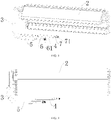
FIG. 1 is a schematic view of an air conditioning indoor unit according to some embodiments of the present disclosure; -
FIG. 2 is a schematic view of an air conditioning indoor unit in another direction according to some embodiments of the present disclosure; -
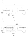
FIG. 3 is a schematic view illustrating connection of a heat exchanger, a first silencer tube, and a second silencer tube according to some embodiments of the present disclosure; -
FIG. 4 is a schematic view illustrating connection of a heat exchanger, a first silencer tube, and a second silencer tube in another direction according to some embodiments of the present disclosure; -
FIG. 5 is a sectional view of a first silencer according to some embodiments of the present disclosure; -
FIG. 6 is a sectional view of a first silencer according to some other embodiments of the present disclosure; -
FIG. 7 is a sectional view of a second silencer according to some embodiments of the present disclosure; -
FIG. 8 is a sectional view of a second silencer according to some other embodiments of the present disclosure; -
FIG. 9 is a sectional view of a third silencer according to some embodiments of the present disclosure; -
FIG. 10 is a sectional view of a third silencer according to some other embodiments of the present disclosure. - Reference numerals:
- air conditioning
indoor unit 100; -
housing 1; -
heat exchanger 2; -
first silencer 3;first connection tube 31;second connection tube 32; first through-hole 321;first body 33;first silencing cavity 331; -
second silencer 4; first communicatingtube 41; second communicatingtube 42; second through-hole 421;second body 43;second silencing cavity 431; -
third silencer 5; firstjoint pipe 51; secondjoint pipe 52; third through-hole 521;third body 53;third silencing cavity 531; -
first refrigerant tube 6; low-pressuretube connection bolt 61; - second refrigerant tube 7; high-pressure
tube connection bolt 71. - Embodiments of the present disclosure will be described below in detail. Examples of the embodiments are illustrated in the accompanying drawings, where the same or similar reference numerals throughout the specification refer to the same or similar elements or elements having the same or similar functions. The embodiments described below with reference to the accompanying drawings are exemplary and are intended to explain the present disclosure rather than limit the present disclosure.
- An air conditioning
indoor unit 100 according to embodiments of the present disclosure will be described below with reference to the accompanying drawings. The air conditioningindoor unit 100 can be assembled with an air conditioning outdoor unit to form an air conditioner and to regulate an indoor ambient temperature. Optionally, the air conditioningindoor unit 100 is a wall-mounted air conditioning indoor unit or a floor-mounted air conditioning indoor unit. - As shown in
FIGS. 1-2 , the air conditioningindoor unit 100 according to an embodiment of the present disclosure may include ahousing 1, aheat exchanger 2, afirst silencer 3, and asecond silencer 4. - Specifically, the
heat exchanger 2, thefirst silencer 3 and thesecond silencer 4 may all be located in thehousing 1, with thefirst silencer 3 being coupled to a first end of theheat exchanger 2 and thesecond silencer 4 being coupled to a second end of theheat exchanger 2. - Specifically, in a cooling mode, a high-temperature and high-pressure refrigerant discharged from a compressor first flows to the
outdoor heat exchanger 2, the refrigerant from theoutdoor heat exchanger 2 may flow to the second end of theheat exchanger 2 after being silenced by thesecond silencer 4 and exchange heat in theheat exchanger 2, and the refrigerant after the heat exchange may flow to thefirst silencer 3 through the first end of theheat exchanger 2; in a heating mode, the high-temperature and high-pressure refrigerant discharged from the compressor flows to thefirst silencer 3, further flows to theheat exchanger 2 through the first end of theheat exchanger 2 after being silenced by thefirst silencer 3 and exchanges heat in theheat exchanger 2, and the refrigerant after the heat exchange may flow to thesecond silencer 4 through the second end of theheat exchanger 2. - It is known to those skilled in the art that the silencing principle of silencers is to form an abrupt change in a cross section between two ends of a pipeline and a middle part of the pipeline (forming an expansion chamber), so that impedance mismatch occurs during the flow of sound waves emitted by the compressor through the silencer, making part of the sound waves interfere with the original sound waves, and reducing noise.
- Therefore, by arranging the
first silencer 3 and thesecond silencer 4 within thehousing 1, and making thefirst silencer 3 coupled to the first end of theheat exchanger 2 and thesecond silencer 4 coupled to the second end of theheat exchanger 2, thesecond silencer 4 can be used for silencing during cooling and thefirst silencer 3 can be used for silencing during heating, to reduce radiation of acoustic energy from the compressor to theheat exchanger 2, achieve the purpose of silencing at a front end of theheat exchanger 2 in different operating conditions, and greatly improve noise transmission from the compressor to the room; moreover, a problem that more silencers or longer low-frequency silencers cannot be arranged due to space limitation in a vertical direction of a compressor compartment can be solved, and the weight of the outdoor unit can be reduced to a certain extent, avoiding deformation and breakage of pipelines of the outdoor unit caused by the fall of the outdoor unit. In addition, a four-way valve silencer of the outdoor unit can be eliminated, which increases the natural frequency of the four-way valve, so that the natural frequency of the four-way valve is less likely to resonate with the natural frequency of the compressor, and the pipeline design difficulty can be lowered. Furthermore, when the refrigerant flows through the first silencer and the second silencer, a cross-sectional area in the middle is larger than a cross-sectional area at either ends after the abrupt change in the cross section of the silencer, which is conducive to improving the heat transfer efficiency and enhancing the cooling/heating performance. - For the air conditioning
indoor unit 100 according to the embodiments of the present disclosure, by arranging thefirst silencer 3 and thesecond silencer 4 within thehousing 1, and making thefirst silencer 3 coupled to the first end of theheat exchanger 2 and thesecond silencer 4 coupled to the second end of theheat exchanger 2, thesecond silencer 4 can be used for silencing during cooling and thefirst silencer 3 can be used for silencing during heating, to reduce radiation of acoustic energy from the compressor to theheat exchanger 2, achieve the purpose of silencing at the front end of theheat exchanger 2 in different operating conditions, and greatly improve noise transmission from the compressor to the room; moreover, the problem that more silencers or longer low-frequency silencers cannot be arranged due to space limitation in the vertical direction of the compressor compartment can be solved, and the weight of the outdoor unit can be reduced to a certain extent, avoiding deformation and breakage of pipelines of the outdoor unit caused by the fall of the outdoor unit. In addition, the four-way valve silencer of the outdoor unit can be eliminated, which increases the natural frequency of the four-way valve, so that the natural frequency of the four-way valve is less likely to resonate with the natural frequency of the compressor, and the pipeline design difficulty can be lowered. Furthermore, when the refrigerant flows through the first silencer and the second silencer, the cross-sectional area in the middle is larger than the cross-sectional area at either ends after the abrupt change in the cross section of the silencer, which is conducive to improving the heat transfer efficiency and enhancing the cooling/heating performance. - Referring to
FIGS. 5 and 6 , in some embodiments of the present disclosure, thefirst silencer 3 includes afirst body 33, afirst connection tube 31, and asecond connection tube 32; thefirst body 33 forms afirst silencing cavity 331; thefirst connection tube 31 is coupled to an end of thefirst body 33 and the first end of theheat exchanger 2; and thesecond connection tube 32 is coupled to an other end of thefirst body 33 and inserted into thefirst silencing cavity 331. Thus, by inserting thesecond connection tube 32 into the first silencingcavity 331, a position of an impedance mismatch interface within the first silencingcavity 331 can be changed, the silencing volume near a passing frequency can be improved, and a silencing function of a specific frequency band can be realized with a good effect. - Specifically, for example, as shown in
FIGS. 5-6 , thefirst connection tube 31 is coupled to one axial end of thefirst body 33 and the first end of theheat exchanger 2, and thesecond connection tube 32 is coupled to the other axial end of thefirst body 33 and inserted into the first silencingcavity 331. Optionally, respective axes of thefirst connection tube 31, thefirst body 33 and thesecond connection tube 32 are parallel to each other. For example, the axes of thefirst connection tube 31, thefirst body 33 and thesecond connection tube 32 are co-linear. Thus, the structure is simple and the silencing effect is good. - Optionally, as shown in
FIG. 5 , an end of thesecond connection tube 32 located in the first silencingcavity 331 is open, so that circulation of the refrigerant between the first silencingcavity 331 and thesecond connection tube 32 is facilitated, and the structure is simple. - Certainly, the present disclosure is not limited thereto. As shown in
FIG. 6 , the end of thesecond connection tube 32 located in the first silencingcavity 331 is closed, and a plurality of first through-holes 321 are formed on a peripheral wall of a part, located in the first silencingcavity 331, of thesecond connection tube 32. Thus, for transmitted sound of specific frequencies, the Helmholtz resonator principle can be used, so that the acoustic energy flowing through thesecond connection tube 32 is absorbed due to resonance, and the silencing effect is improved. - In some embodiments of the present disclosure, the first through-
hole 321 has a diameter ranging from 0.05 mm to 5 mm. It can be understood that the smaller the diameter is, the better the silencing effect is. Thus, the silencing effect is further enhanced. - For example, the diameter of the first through-
hole 321 may be 0.1 mm, 0.3 mm, 0.5 mm, 1 mm, 1.2 mm, 1.6 mm, 2 mm, 2.5 mm, 3 mm, 3.4 mm, 3.9 mm, 4 mm, 4.5 mm or etc. - Optionally, the number of the first through-
holes 321 may be two, five or eight. It can be understood that the smaller the number of holes is, the lower the frequency that can be eliminated is. Thus, it is beneficial to eliminate noise at low frequencies. - In some embodiments of the present disclosure, as shown in
FIG. 6 , a distance between the first through-hole 321 farthest away from the closed end of thesecond connection tube 32 and an end of the first silencingcavity 331 adjacent to thesecond connection tube 32 is greater than 5 mm. That is, the distance between the first through-hole 321 farthest away from the closed end of thesecond connection tube 32 and a side wall of the first silencingcavity 331 for thesecond connection tube 32 to pass through is denoted as L1 which is greater than 5 mm. Thus, the silencing effect can be further enhanced, and the processing and manufacturing can be facilitated. - For example, L1 may be 5.5 mm, 6 mm, 6.4 mm, 6.8 mm, 7 mm or 8 mm.
- In some optional embodiments of the present disclosure, the plurality of first through-
holes 321 are divided into a plurality of groups, each group including at least two first through-holes 321. The first through-holes 321 in each group are spaced along an axial direction of thesecond connection tube 32; the plurality of groups of first through-holes 321 are spaced along a peripheral direction of thesecond connection tube 32; and two adjacent groups of first through-holes 321 are staggered in the peripheral direction of thesecond connection tube 32. For example, as shown inFIG. 6 , fourteen first through-holes 321 are divided into four groups, in which two groups have four first through-holes 321 and the other two groups have three first through-holes 321. The first through-holes 321 in each group are spaced apart from one another in the axial direction of thesecond connection tube 32; four groups of first through-holes 321 are spaced apart from one another in the peripheral direction of thesecond connection tube 32; and two adjacent groups of first through-holes 321 are staggered in the peripheral direction of thesecond connection tube 32. Thus, the silencing effect can be further improved. - Optionally, with reference to
FIG. 6 , in the two adjacent groups of first through-holes 321, a line connecting centers of two adjacent first through-holes 321 and a central axis of thesecond connection tube 32 form an angle α ranging from 30° to 60°. That is, one of the two adjacent first through-holes 321 belongs to one group of first through-holes 321, the other of the two adjacent first through-holes 321 belongs to the other group of first through-holes 321, and these two groups of first through-holes 321 are adjacent, in which the angle α between the line connecting centers of the two adjacent first through-holes 321 and the central axis of thesecond connection tube 32 ranges from 30° to 60°. For example, the angle α is such as 35°, 40°, 45°, 48°, 50°, 55° or etc. - Optionally, a distance between two adjacent first through-
holes 321 in each group of first through-holes 321 is greater than 5 mm, thereby further improving the silencing effect and facilitating processing and manufacturing. For example, the distance between the two adjacent first through-holes 321 is 5.5 mm, 6 mm, 6.4 mm, 6.8 mm, 7 mm, or 8 mm. - In some embodiments of the present disclosure, the
first connection tube 31 is inserted into the first silencingcavity 331, and a length of thesecond connection tube 32 located in the first silencingcavity 331 is greater than a length of thefirst connection tube 31 located in the first silencingcavity 331. Thus, it is conducive to improving the silencing effect of thefirst silencer 3 in the heating mode. - Optionally, the length of the
second connection tube 32 located in the first silencingcavity 331 and the length of thefirst connection tube 31 located in the first silencingcavity 331 are both not greater than one quarter of the length of thefirst silencer 3. That is, the length of thesecond connection tube 32 located in the first silencingcavity 331 is not greater than one quarter of the length of thefirst silencer 3, and the length of thefirst connection tube 31 located in the first silencingcavity 331 is not greater than one quarter of the length of thefirst silencer 3. The length of thefirst connection tube 31 located in the first silencingcavity 331 and the length of thesecond connection tube 32 located in the first silencingcavity 331 may be equal or may be unequal. Specifically, referring toFIGS. 5 and 6 , the length of thefirst silencer 3 is L2, the length of thefirst connection tube 31 in the first silencingcavity 331 is L3, and the length of thesecond connection tube 32 in the first silencingcavity 331 is L4, in which L2, L3 and L4 satisfy L3≤1/4L2 and L4≤1/4L2. Thus, the structure of thefirst silencer 3 is reasonably optimized and the silencing effect is improved. - Certainly, it can be understood that the
first connection tube 31 may also not be inserted into the first silencingcavity 331, and thefirst connection tube 31 is just coupled to a connection port of the first silencingcavity 331 to be in communication with the first silencingcavity 331; the length of thesecond connection tube 32 located in the first silencingcavity 331 is not greater than a half of the length of thefirst silencer 3, i.e., L4≤1/2L2. Thus, the silencing effect of thefirst silencer 3 in the heating mode can be improved. - Referring to
FIGS. 7 and 8 , in some embodiments of the present disclosure, thesecond silencer 4 includes asecond body 43, a first communicatingtube 41 and a second communicatingtube 42. Thesecond body 43 forms a second silencingcavity 431. The first communicatingtube 41 is coupled to a first end of thesecond body 43 and the second end of theheat exchanger 2. The second communicatingtube 42 is coupled to a second end of thesecond body 43, and the second communicatingtube 42 is inserted into the second silencingcavity 431. Thus, by inserting the second communicatingtube 42 into the second silencingcavity 431, a position of an impedance mismatch interface within the second silencingcavity 431 can be changed, the silencing volume near a passing frequency can be improved, and a silencing function of a specific frequency band can be realized with a good effect. - Specifically, for example, as shown in
FIGS. 7-8 , the first communicatingtube 41 is coupled to one axial end of thesecond body 43 and the second end of theheat exchanger 2, and the second communicatingtube 42 is coupled to the other axial end of thesecond body 43 and inserted into the second silencingcavity 431. Optionally, respective axes of the first communicatingtube 41, thesecond body 43, and the second communicatingtube 42 are parallel to each other. For example, the axes of the first communicatingtube 41, thesecond body 43, and the second communicatingtube 42 are co-linear. Thus, the structure is simple and the silencing effect is good. - Optionally, as shown in
FIG. 7 , an end of the second communicatingtube 42 located in the second silencingcavity 431 is open, so that circulation of the refrigerant between the second silencingcavity 431 and the second communicatingtube 42 is facilitated, and the structure is simple. - Certainly, the present disclosure is not limited thereto. As shown in
FIG. 8 , the end of the second communicatingtube 42 located in the second silencingcavity 431 is closed, and a plurality of second through-holes 421 are formed on a peripheral wall of a part, located in the second silencingcavity 431, of the second communicatingtube 42. Thus, for transmitted sound of specific frequencies, the Helmholtz resonator principle can be used, so that the acoustic energy flowing through the second communicatingtube 42 is absorbed due to resonance, and the silencing effect is improved. - In some embodiments of the present disclosure, the second through-
hole 421 has a diameter ranging from 0.05 mm to 5 mm. It can be understood that the smaller the diameter is, the better the silencing effect is. Thus, the silencing effect is further enhanced. - For example, the diameter of the second through-
hole 421 may be 0.1 mm, 0.3 mm, 0.5 mm, 1 mm, 1.2 mm, 1.6 mm, 2 mm, 2.5 mm, 3 mm, 3.4 mm, 3.9 mm, 4 mm, 4.5 mm or etc. - Optionally, the number of the second through-
holes 421 may be two, five or eight. It can be understood that the smaller the number of holes is, the lower the frequency that can be eliminated is. Thus, it is beneficial to eliminate noise at low frequencies. - In some embodiments of the present disclosure, as shown in
FIG. 8 , a distance between the second through-hole 421 farthest away from the closed end of the second communicatingtube 42 and an end of the second silencingcavity 431 adjacent to the second communicatingtube 42 is greater than 5 mm. That is, the distance between the second through-hole 421 farthest away from the closed end of the second communicatingtube 42 and a side wall of the second silencingcavity 431 for the second communicatingtube 42 to pass through is denoted as L5 which is greater than 5 mm. Thus, the silencing effect can be further enhanced, and the processing and manufacturing can be facilitated. - For example, L5 may be 5.5 mm, 6 mm, 6.4 mm, 6.8 mm, 7 mm or 8 mm.
- In some optional embodiments of the present disclosure, the plurality of second through-
holes 421 are divided into a plurality of groups, each group including at least two second through-holes 421. The second through-holes 421 in each group are spaced along an axial direction of the second communicatingtube 42; the plurality of groups of second through-holes 421 are spaced along a peripheral direction of the second communicatingtube 42; and two adjacent groups of second through-holes 421 are staggered in the peripheral direction of the second communicatingtube 42. For example, as shown inFIG. 8 , fourteen second through-holes 421 are divided into four groups, in which two groups have four second through-holes 421 and the other two groups have three second through-holes 421. The second through-holes 421 in each group are spaced apart from one another in the axial direction of the second communicatingtube 42; four groups of second through-holes 421 are spaced apart from one another in the peripheral direction of the second communicatingtube 42; and two adjacent groups of second through-holes 421 are staggered in the peripheral direction of the second communicatingtube 42. Thus, the silencing effect can be further improved. - Optionally, with reference to
FIG. 8 , in the two adjacent groups of second through-holes 421, a line connecting centers of two adjacent second through-holes 421 and a central axis of the second communicatingtube 42 form an angle β ranging from 30° to 60°. That is, one of the two adjacent second through-holes 421 belongs to one group of second through-holes 421, the other of the two adjacent second through-holes 421 belongs to the other group of second through-holes 421, and these two groups of second through-holes 421 are adjacent, in which the angle β between the line connecting centers of the two adjacent second through-holes 421 and the central axis of the second communicatingtube 42 ranges from 30° to 60°. For example, the angle β is such as 35°, 40°, 45°, 48°, 50°, 55° or etc. - Optionally, a distance between two adjacent second through-
holes 421 in each group of second through-holes 421 is greater than 5 mm, thereby further improving the silencing effect and facilitating processing and manufacturing. For example, the distance between the two adjacent second through-holes 421 is 5.5 mm, 6 mm, 6.4 mm, 6.8 mm, 7 mm, or 8 mm. - In some embodiments of the present disclosure, the first communicating
tube 41 is inserted into the second silencingcavity 431, and a length of the second communicatingtube 42 located in the second silencingcavity 431 is greater than a length of the first communicatingtube 41 located in the second silencingcavity 431. Thus, it is conducive to improving the silencing effect of thesecond silencer 4 in the cooling mode. - Optionally, the length of the second communicating
tube 42 located in the second silencingcavity 431 and the length of the first communicatingtube 41 located in the second silencingcavity 431 are both not greater than one quarter of the length of thesecond silencer 4. That is, the length of the second communicatingtube 42 located in the second silencingcavity 431 is not greater than one quarter of the length of thesecond silencer 4, and the length of the first communicatingtube 41 located in the second silencingcavity 431 is not greater than one quarter of the length of thesecond silencer 4. The length of the first communicatingtube 41 located in the second silencingcavity 431 and the length of the second communicatingtube 42 located in the second silencingcavity 431 may be equal or may be unequal. Specifically, referring toFIG. 8 , the length of thesecond silencer 4 is L6, the length of the first communicatingtube 41 in the second silencingcavity 431 is L7, and the length of the second communicatingtube 42 in the second silencingcavity 431 is L8, in which L6, L7 and L8 satisfy L7≤1/4L6 and L8≤1/4L6. Thus, the structure of thesecond silencer 4 is reasonably optimized and the silencing effect is improved. - Certainly, it can be understood that the first communicating
tube 41 may also not be inserted into the second silencingcavity 431, and the first communicatingtube 41 is just coupled to a connection port of the second silencingcavity 431 to be in communication with the second silencingcavity 431; the length of the second communicatingtube 42 located in the second silencingcavity 431 is not greater than a half of the length of thesecond silencer 4, i.e., L8≤1/2L6. - According to some embodiments of the present disclosure, the air conditioning
indoor unit 100 further includes athird silencer 5 coupled to an end of thefirst silencer 3 away from theheat exchanger 2. Specifically, in the heating mode, the high-temperature and high-pressure refrigerant discharged from the compressor flows to thethird silencer 5, then flows to thefirst silencer 3, and further flows to theheat exchanger 2 through the first end of theheat exchanger 2 after being silenced by thefirst silencer 3 and exchanges heat in theheat exchanger 2, such that the refrigerant after the heat exchange can flow to thesecond silencer 4 through the second end of theheat exchanger 2. Thus, in the heating mode, the purpose of two-stage silencing at the front end of theheat exchanger 2 can be achieved, and the radiation of acoustic energy from the compressor to theheat exchanger 2 during heating can be further reduced to improve the silencing effect. - Certainly, it can be understood that the air conditioning
indoor unit 100 may also include a fourth silencer, which may be coupled to an end of thesecond silencer 4 away from theheat exchanger 2. Specifically, for example, in the cooling mode, the high-temperature and high-pressure refrigerant discharged from the compressor first flows to theoutdoor heat exchanger 2, and the refrigerant flowing from theoutdoor heat exchanger 2 may flow to the second end of theheat exchanger 2 after being silenced by the fourth silencer and thesecond silencer 4 and exchange heat in theheat exchanger 2, such that the refrigerant after the heat exchange may flow to thefirst silencer 3 through the first end of theheat exchanger 2. Thus, in the cooling mode, the purpose of two-stage silencing at the front end of theheat exchanger 2 can be achieved, and the radiation of acoustic energy from the compressor to theheat exchanger 2 during cooling can be further reduced to improve the silencing effect. - According to some embodiments of the present disclosure, a cross-sectional area of the second silencing
cavity 431 of thesecond silencer 4 is smaller than a cross-sectional area of a third silencingcavity 531 of thethird silencer 5, and the cross-sectional area of the third silencingcavity 531 is smaller than the cross-sectional area of the first silencingcavity 331 of thefirst silencer 3. The above arrangement is conducive to adjusting expansion ratios of thefirst silencer 3 to thethird silencer 5, and silencers with different expansion ratios are adopted to achieve multi-stage silencing and improve the silencing effect. - In some optional embodiments of the present disclosure, the length of the
second silencer 4 is greater than the length of thethird silencer 5, and the length of thethird silencer 5 is greater than the length of thefirst silencer 3. It can be understood that the longer the silencer is, the better the silencing effect on sound transmitted at low frequency is. Since the compressor noise at certain frequencies is still loud after passing through the silencers, sound transmitted at different frequencies can be silenced by making the lengths of thefirst silencer 3 to thethird silencer 5 different, which can improve the silencing effect. - It can be understood that particular specifications of the silencers can be selected according to the cooling/heating conditions and the transmission frequency of the compressor sound.
- Optionally, the
first silencer 3, thesecond silencer 4 and thethird silencer 5 have different expansion ratios. Since the compressor noise at certain frequencies is still loud after passing through the silencers, the silencing effect can be improved through multi-stage silencing realized by adopting silencers with different expansion ratios. Optionally, the expansion ratios of thefirst silencer 3, thesecond silencer 4 and thethird silencer 5 are values greater than 1 and less than 10. Thus, it is conducive to improving the silencing effect. - Referring to
FIGS. 9 and 10 , in some embodiments of the present disclosure, thethird silencer 5 includes athird body 53, a firstjoint pipe 51 and a secondjoint pipe 52. Thethird body 53 forms a third silencingcavity 531. The firstjoint pipe 51 is coupled to a first end of thethird body 53 and thesecond connection tube 32. The secondjoint pipe 52 is coupled to a second end of thethird body 53, and the secondjoint pipe 52 is inserted into the third silencingcavity 531. Thus, by inserting the secondjoint pipe 52 into the third silencingcavity 531, a position of an impedance mismatch interface within the third silencingcavity 531 can be changed, the silencing volume near a passing frequency can be improved, and a silencing function of a specific frequency band can be realized with a good effect. - Specifically, for example, as shown in FIGS. 11-12, the first
joint pipe 51 is coupled to one axial end of thethird body 53 and the second end of thesecond connection tube 32, and the secondjoint pipe 52 is coupled to the other axial end of thethird body 53 and inserted into the third silencingcavity 531. Optionally, respective axes of the firstjoint pipe 51, the secondjoint pipe 52, and thethird body 53 are parallel to each other. For example, the axes of the firstjoint pipe 51, the secondjoint pipe 52, and thethird body 53 are co-linear. Thus, the structure is simple and the silencing effect is good. - Optionally, as shown in
FIG. 9 , an end of the secondjoint pipe 52 located in the third silencingcavity 531 is open, so that circulation of the refrigerant between the third silencingcavity 531 and the secondjoint pipe 52 is facilitated, and the structure is simple. - Certainly, the present disclosure is not limited thereto. As shown in
FIG. 10 , the end of the secondjoint pipe 52 located in the third silencingcavity 531 is closed, and a plurality of third through-holes 521 are formed on a peripheral wall of a part, located in the third silencingcavity 531, of the secondjoint pipe 52. Thus, for transmitted sound of specific frequencies, the Helmholtz resonator principle can be used, so that the acoustic energy flowing through the secondjoint pipe 52 is absorbed due to resonance, and the silencing effect is improved. - In some embodiments of the present disclosure, the third through-
hole 521 has a diameter ranging from 0.05 mm to 5 mm. It can be understood that the smaller the diameter is, the better the silencing effect is. Thus, the silencing effect is further enhanced. - For example, the diameter of the third through-
hole 521 may be 0.1 mm, 0.3 mm, 0.5 mm, 1 mm, 1.2 mm, 1.6 mm, 2 mm, 2.5 mm, 3 mm, 3.4 mm, 3.9 mm, 4 mm, 4.5 mm or etc. - Optionally, the number of the third through-
holes 521 may be two, five or eight. It can be understood that the smaller the number of holes is, the lower the frequency that can be eliminated is. Thus, it is beneficial to eliminate noise at low frequencies. - In some embodiments of the present disclosure, as shown in
FIG. 10 , a distance between the third through-hole 521 farthest away from the closed end of the secondjoint pipe 52 and an end of the third silencingcavity 531 adjacent to the secondjoint pipe 52 is greater than 5 mm. That is, the distance between the third through-hole 521 farthest away from the closed end of the secondjoint pipe 52 and a side wall of the third silencingcavity 531 for the secondjoint pipe 52 to pass through is denoted as L9 which is greater than 5 mm. Thus, the silencing effect can be further enhanced, and the processing and manufacturing can be facilitated. - For example, L9 may be 5.5 mm, 6 mm, 6.4 mm, 6.8 mm, 7 mm or 8 mm.
- In some optional embodiments of the present disclosure, the plurality of third through-
holes 521 are divided into a plurality of groups, each group including at least two third through-holes 521. The third through-holes 521 in each group are spaced along an axial direction of the secondjoint pipe 52; the plurality of groups of third through-holes 521 are spaced along a peripheral direction of the secondjoint pipe 52; and two adjacent groups of third through-holes 521 are staggered in the peripheral direction of the secondjoint pipe 52. For example, as shown inFIG. 10 , fourteen third through-holes 521 are divided into four groups, in which two groups have four third through-holes 521 and the other two groups have three third through-holes 521. The third through-holes 521 in each group are spaced apart from one another in the axial direction of the secondjoint pipe 52; four groups of third through-holes 521 are spaced apart from one another in the peripheral direction of the secondjoint pipe 52; and two adjacent groups of third through-holes 521 are staggered in the peripheral direction of the secondjoint pipe 52. Thus, the silencing effect can be further improved. - Optionally, with reference to
FIG. 10 , in the two adjacent groups of third through-holes 521, a line connecting centers of two adjacent third through-holes 521 and a central axis of the secondjoint pipe 52 form an angle γ ranging from 30° to 60°. That is, one of the two adjacent third through-holes 521 belongs to one group of third through-holes 521, the other of the two adjacent third through-holes 521 belongs to the other group of third through-holes 521, and these two groups of third through-holes 521 are adjacent, in which the angle γ between the line connecting centers of the two adjacent third through-holes 521 and the central axis of the secondjoint pipe 52 ranges from 30° to 60°. For example, the angle γ is such as 35°, 40°, 45°, 48°, 50°, 55° or etc. - Optionally, a distance between two adjacent third through-
holes 521 in each group of third through-holes 521 is greater than 5 mm, thereby further improving the silencing effect and facilitating processing and manufacturing. For example, the distance between the two adjacent third through-holes 521 is 5.5 mm, 6 mm, 6.4 mm, 6.8 mm, 7 mm, or 8 mm. - In some embodiments of the present disclosure, the first
joint pipe 51 is inserted into the third silencingcavity 531, and a length of the secondjoint pipe 52 located in the third silencingcavity 531 is greater than a length of the firstjoint pipe 51 located in the third silencingcavity 531. Thus, it is conducive to improving the silencing effect of thethird silencer 5 in the heating mode. - Optionally, the length of the second
joint pipe 52 located in the third silencingcavity 531 and the length of the firstjoint pipe 51 located in the third silencingcavity 531 are both not greater than one quarter of the length of thethird silencer 5. That is, the length of the secondjoint pipe 52 located in the third silencingcavity 531 is not greater than one quarter of the length of thethird silencer 5, and the length of the firstjoint pipe 51 located in the third silencingcavity 531 is not greater than one quarter of the length of thethird silencer 5. The length of the firstjoint pipe 51 located in the third silencingcavity 531 and the length of the secondjoint pipe 52 located in the third silencingcavity 531 may be equal or may be unequal. Specifically, referring toFIG. 10 , the length of thethird silencer 5 is L10, the length of the firstjoint pipe 51 in the third silencingcavity 531 is L11, and the length of the secondjoint pipe 52 in the third silencingcavity 531 is L12, in which L10, L11 and L12 satisfy L11≤1/4L10 and L12≤1/4L10. Thus, the structure of thethird silencer 5 is reasonably optimized and the silencing effect is improved. - Certainly, it can be understood that the first
joint pipe 51 may also not be inserted into the third silencingcavity 531, and the firstjoint pipe 51 is just coupled to a connection port of the third silencingcavity 531 to be in communication with the third silencingcavity 531; the length of the secondjoint pipe 52 located in the third silencingcavity 531 is not greater than a half of the length of thethird silencer 5, i.e., L12≤1/2L10. - In some embodiments of the present disclosure, the
first silencer 3 extends along a width direction of the housing (e.g., an up-down direction inFIG. 1 ), and thesecond silencer 4 extends along a length direction of the housing (e.g., a left-right direction inFIG. 1 ). Specifically, for example, the air conditioningindoor unit 100 is a wall-mounted air conditioning indoor unit; thefirst silencer 3, thesecond silencer 4, and thethird silencer 5 are all located on a rear side of theheat exchanger 2; and at least a part of a projection of thefirst silencer 3, at least a part of a projection of thesecond silencer 4, and at least a part of a projection of thethird silencer 5 are all located in a projection of the heat exchanger in a plane perpendicular to a front-rear direction, in which the length direction of the housing is the left-right direction, and the width direction of the housing is the up-and-down direction. As another example, the air conditioningindoor unit 100 is a floor-mounted air conditioningindoor unit 100; thefirst silencer 3, thesecond silencer 4 and thethird silencer 5 are all located at the rear side of theheat exchanger 2; and at least a part of a projection of thefirst silencer 3, at least a part of a projection of thesecond silencer 4, and at least a part of a projection of thethird silencer 5 are all located in a projection of the heat exchanger in a plane perpendicular to a front-rear direction, in which the length direction of the housing is the up-down direction, and the width direction of the housing is the left-right direction. Thus, the specific structure of the housing can be fully utilized to arrange the first silencer and thesecond silencer 4 without increasing the volume of the housing. - In some optional embodiments of the present disclosure, as shown in
FIG. 1 , the air conditioningindoor unit 100 further includes a firstrefrigerant tube 6 and a second refrigerant tube 7; the firstrefrigerant tube 6 is coupled to the first end of theheat exchanger 2 and the second refrigerant tube 7 is coupled to the second end of theheat exchanger 2; thefirst silencer 3 and thethird silencer 5 are coupled in series in the firstrefrigerant tube 6 and thesecond silencer 4 is coupled in series in the second refrigerant tube 7. Thus, the structure is simple, which facilitates the connection of the air conditioningindoor unit 100 to the air conditioning outdoor unit. - Optionally, the first
refrigerant tube 6 is coupled with a low-pressuretube connection bolt 61 at an end of the firstrefrigerant tube 6 away from theheat exchanger 2, and the second refrigerant tube 7 is coupled with a high-pressuretube connection bolt 71 at an end of the second refrigerant tube 7 away from theheat exchanger 2, which facilitates the connection of the air conditioningindoor unit 100 to the air conditioning outdoor unit. - In the description of the present disclosure, it is to be understood that terms such as "central," "length," "width," "upper," "lower," "front," "rear," "left," "right," "vertical," "horizontal," "top," "bottom," "inner," "outer," "axial," "circumferential" and the like should be construed to refer to orientations or positions as then described or as shown in the drawings under discussion. These relative terms are for convenience of description and do not indicate or imply that the device or element referred to must have a particular orientation or be constructed or operated in a particular orientation. Thus, these terms shall not be construed as limitations on the present disclosure. In the description of the present disclosure, "a plurality of' means two or more than two. In the description of the present disclosure, a structure in which a first feature is "on" or "below" a second feature may include an embodiment in which the first feature is in direct contact with the second feature, and may also include an embodiment in which the first feature and the second feature are not in direct contact with each other, but are contacted via an additional feature formed therebetween. In the description of the present disclosure, a first feature "on," "above," or "on top of' a second feature may include an embodiment in which the first feature is right or obliquely "on," "above," or "on top of' the second feature, or just means that the first feature is at a height higher than that of the second feature.
- Reference throughout this specification to "an embodiment," "some embodiments," "an exemplary embodiment," "an example," "a specific example" or "some examples" means that a particular feature, structure, material, or characteristic described in connection with the embodiment or example is included in at least one embodiment or example of the present disclosure. Thus, the appearances of the phrases throughout this specification are not necessarily referring to the same embodiment or example of the present disclosure. Furthermore, the particular features, structures, materials, or characteristics may be combined in any suitable manner in one or more embodiments or examples.
- Although embodiments of the present disclosure have been shown and described, it would be appreciated by those skilled in the art that changes, modifications, alternatives, and variations can be made in the embodiments without departing from principles and purposes of the present disclosure. The scope of the present disclosure is defined by the claims and their equivalents.
Claims (11)
- An air conditioning indoor unit, comprising:a housing;a heat exchanger arranged in the housing;a first silencer arranged in the housing and coupled to a first end of the heat exchanger; anda second silencer arranged in the housing and coupled to a second end of the heat exchanger.
- The air conditioning indoor unit according to claim 1, further comprising a third silencer coupled to an end of the first silencer away from the heat exchanger.
- The air conditioning indoor unit according to claim 2, wherein a length of the second silencer is greater than a length of the third silencer, and the length of the third silencer is greater than a length of the first silencer.
- The air conditioning indoor unit according to claim 2, wherein a cross-sectional area of a second silencing cavity of the second silencer is smaller than a cross-sectional area of a third silencing cavity of the third silencer, and the cross-sectional area of the third silencing cavity is smaller than a cross-sectional area of a first silencing cavity of the first silencer.
- The air conditioning indoor unit according to claim 1, wherein:the first silencer comprises a first body, a first connection tube, and a second connection tube, the first body forming a first silencing cavity;the first connection tube is coupled to an end of the first body and the first end of the heat exchanger;the second connection tube is coupled to an other end of the first body and inserted into the first silencing cavity;the second silencer comprises a second body, a first communicating tube and a second communicating tube, the second body forming the second silencing cavity;the first communicating tube is coupled to an end of the second body and the second end of the heat exchanger;the second communicating tube is coupled to an other end of the second body and inserted into the second silencing cavity;a refrigerant flows from the second end of the heat exchanger to the first end of the heat exchanger in a cooling mode, and the refrigerant flows from the first end of the heat exchanger to the second end of the heat exchanger in a heating mode;wherein an end of the second connection tube located in the first silencing cavity is closed, and a plurality of first through-holes are formed on a peripheral wall of a part, located in the first silencing cavity, of the second connection tube; and/or an end of the second communicating tube located in the second silencing cavity is closed, and a plurality of second through-holes are formed on a peripheral wall of a part, located in the second silencing cavity, of the second communicating tube.
- The air conditioning indoor unit according to claim 5, wherein the first through-hole has a diameter ranging from 0.05 mm to 5 mm, and/or the second through-hole has a diameter ranging from 0.05 mm to 5 mm.
- The air conditioning indoor unit according to claim 5, wherein:a distance between the first through-hole farthest away from the closed end of the second connection tube and an end of the first silencing cavity adjacent to the second connection tube is greater than 5 mm; and/ora distance between the second through-hole farthest away from the closed end of the second communicating tube and an end of the second silencing cavity adjacent to the second communicating tube is greater than 5 mm.
- The air conditioning indoor unit according to claim 5, wherein:the plurality of first through-holes are divided into a plurality of groups, each group comprising at least two first through-holes,the first through-holes in each group are spaced along an axial direction of the second connection tube, the plurality of groups of first through-holes are spaced along a peripheral direction of the second connection tube, and two adjacent groups of first through-holes are staggered in the peripheral direction of the second connection tube; and/orthe plurality of second through-holes are divided into a plurality of groups, each group comprising at least two second through-holes,the second through-holes in each group are spaced along an axial direction of the second communicating tube, the plurality of groups of second through-holes are spaced along a peripheral direction of the second communicating tube, and two adjacent groups of second through-holes are staggered in the peripheral direction of the second communicating tube.
- The air conditioning indoor unit according to claim 1, whereinthe first silencer comprises a first body, a first connection tube, and a second connection tube, the first body forming a first silencing cavity;the first connection tube is coupled to an end of the first body and the first end of the heat exchanger and is inserted into the first silencing cavity;the second connection tube is coupled to an other end of the first body and inserted into the first silencing cavity;the second silencer comprises a second body, a first communicating tube and a second communicating tube, the second body forming a second silencing cavity;the first communicating tube is coupled to a first end of the second body and the second end of the heat exchanger and is inserted into the first silencing cavity;the second communicating tube is coupled to a second end of the second body and inserted into the second silencing cavity;a refrigerant flows from the second end of the heat exchanger to the first end of the heat exchanger in a cooling mode, and the refrigerant flows from the first end of the heat exchanger to the second end of the heat exchanger in a heating mode;a length of the second connection tube located in the first silencing cavity is greater than a length of the first connection tube located in the first silencing cavity; and/or a length of the second communicating tube located in the second silencing cavity is greater than a length of the second communicating tube located in the second silencing cavity.
- The air conditioning indoor unit according to claim 1, wherein the first silencer comprises a first body, a first connection tube, and a second connection tube, the first body forming a first silencing cavity;the first connection tube is coupled to an end of the first body and the first end of the heat exchanger and is inserted into the first silencing cavity;the second connection tube is coupled to an other end of the first body and inserted into the first silencing cavity;the second silencer comprises a second body, a first communicating tube and a second communicating tube, the second body forming a second silencing cavity;the first communicating tube is coupled to a first end of the second body and the second end of the heat exchanger and is inserted into the first silencing cavity;the second communicating tube is coupled to a second end of the second body and inserted into the second silencing cavity;a length of the second connection tube located in the first silencing cavity and a length of the first connection tube located in the first silencing cavity are both not greater than one quarter of a length of the first silencer; and/or a length of the second communicating tube located in the second silencing cavity and a length of the first communicating tube located in the second silencing cavity are both not greater than one quarter of a length of the second silencer.
- The air conditioning indoor unit according to any one of claims 1 to 10, wherein the first silencer extends along a width direction of the housing, and the second silencer extends along a length direction of the housing.
Applications Claiming Priority (2)
| Application Number | Priority Date | Filing Date | Title |
|---|---|---|---|
| CN201921166353.3U CN210688490U (en) | 2019-07-23 | 2019-07-23 | Air conditioner indoor unit |
| PCT/CN2019/120709 WO2021012546A1 (en) | 2019-07-23 | 2019-11-25 | Air conditioner indoor unit |
Publications (4)
| Publication Number | Publication Date |
|---|---|
| EP3992541A1 true EP3992541A1 (en) | 2022-05-04 |
| EP3992541A4 EP3992541A4 (en) | 2022-08-24 |
| EP3992541C0 EP3992541C0 (en) | 2025-03-12 |
| EP3992541B1 EP3992541B1 (en) | 2025-03-12 |
Family
ID=70902676
Family Applications (1)
| Application Number | Title | Priority Date | Filing Date |
|---|---|---|---|
| EP19938469.4A Active EP3992541B1 (en) | 2019-07-23 | 2019-11-25 | Air conditioner indoor unit |
Country Status (3)
| Country | Link |
|---|---|
| EP (1) | EP3992541B1 (en) |
| CN (1) | CN210688490U (en) |
| WO (1) | WO2021012546A1 (en) |
Families Citing this family (1)
| Publication number | Priority date | Publication date | Assignee | Title |
|---|---|---|---|---|
| CN217979233U (en) * | 2021-04-30 | 2022-12-06 | 浙江盾安禾田金属有限公司 | Silencer and air conditioner with same |
Family Cites Families (10)
| Publication number | Priority date | Publication date | Assignee | Title |
|---|---|---|---|---|
| JPH11325655A (en) * | 1998-05-14 | 1999-11-26 | Matsushita Seiko Co Ltd | Silencers and air conditioners |
| CN2342298Y (en) * | 1998-08-24 | 1999-10-06 | 海尔集团公司 | Silence rfor refrigerating system of air conditioner |
| KR100474908B1 (en) * | 2002-06-12 | 2005-03-08 | 엘지전자 주식회사 | heating and cooling system |
| KR100474909B1 (en) * | 2002-06-12 | 2005-03-08 | 엘지전자 주식회사 | heating and cooling system |
| JP2006098020A (en) * | 2004-09-30 | 2006-04-13 | Mitsubishi Heavy Ind Ltd | Air conditioner and strainer |
| JP2010078288A (en) * | 2008-09-29 | 2010-04-08 | Daikin Ind Ltd | Refrigeration system |
| CN202993509U (en) * | 2012-11-22 | 2013-06-12 | 广东美的电器股份有限公司 | Air conditioner and silencer |
| CN104422109B (en) * | 2013-08-26 | 2018-02-06 | 广东美的暖通设备有限公司 | For air-conditioning silencer and there is its air-conditioning |
| CN204115303U (en) * | 2014-07-29 | 2015-01-21 | 广东美的制冷设备有限公司 | Air conditioner room unit and heat exchanger thereof |
| CN205048595U (en) * | 2015-09-16 | 2016-02-24 | 珠海格力电器股份有限公司 | Connecting pipe for air conditioner and air conditioner |
-
2019
- 2019-07-23 CN CN201921166353.3U patent/CN210688490U/en active Active
- 2019-11-25 WO PCT/CN2019/120709 patent/WO2021012546A1/en not_active Ceased
- 2019-11-25 EP EP19938469.4A patent/EP3992541B1/en active Active
Also Published As
| Publication number | Publication date |
|---|---|
| WO2021012546A1 (en) | 2021-01-28 |
| EP3992541A4 (en) | 2022-08-24 |
| CN210688490U (en) | 2020-06-05 |
| EP3992541C0 (en) | 2025-03-12 |
| EP3992541B1 (en) | 2025-03-12 |
Similar Documents
| Publication | Publication Date | Title |
|---|---|---|
| CN201724362U (en) | Inverter air conditioner silencer | |
| CN210440182U (en) | Suction muffler for refrigeration compressor | |
| CN108443116B (en) | Suction muffler for refrigerator reciprocating compressor | |
| EP3992541B1 (en) | Air conditioner indoor unit | |
| CN211288018U (en) | Silencer, compressor and refrigeration equipment | |
| CN113638865B (en) | Snake-shaped communication pipe silencer for refrigerator compressor | |
| CN116717905A (en) | Adjustable muffler and air conditioner | |
| CN204717920U (en) | Silencer and there is its air-conditioner outdoor unit | |
| CN110274072A (en) | Valve component and air conditioner for air conditioner | |
| CN216346964U (en) | Noise reduction type pipeline and air conditioner | |
| CN106286222B (en) | Muffler and refrigeration compressor | |
| CN111946593A (en) | Air suction silencer and compressor with same | |
| CN208090838U (en) | The piping system and air conditioner of air-conditioner outdoor unit | |
| CN218495352U (en) | Silencer and air conditioner | |
| CN110714901A (en) | Flanged exhaust structures, pump body assemblies, compressors and air conditioners | |
| CN213743898U (en) | Suction muffler with honeycomb hole structure and compressor | |
| JP2025522059A (en) | Air intake mufflers, compressors and electrical equipment | |
| CN218030519U (en) | S-shaped communicating pipe silencer for refrigerator compressor | |
| CN209944714U (en) | Muffler and Air Conditioner | |
| CN212032640U (en) | A kind of resistant muffler and array muffler | |
| CN212535978U (en) | Air suction silencer for air suction at same side of compressor | |
| CN210861788U (en) | Reversing device for heat exchange system and heat exchange system | |
| CN210463276U (en) | Air conditioning system and air conditioner having the same | |
| CN115540089A (en) | Air conditioner outdoor unit and air conditioner | |
| CN221705762U (en) | Muffler and air conditioning |
Legal Events
| Date | Code | Title | Description |
|---|---|---|---|
| STAA | Information on the status of an ep patent application or granted ep patent |
Free format text: STATUS: THE INTERNATIONAL PUBLICATION HAS BEEN MADE |
|
| PUAI | Public reference made under article 153(3) epc to a published international application that has entered the european phase |
Free format text: ORIGINAL CODE: 0009012 |
|
| STAA | Information on the status of an ep patent application or granted ep patent |
Free format text: STATUS: REQUEST FOR EXAMINATION WAS MADE |
|
| 17P | Request for examination filed |
Effective date: 20220126 |
|
| AK | Designated contracting states |
Kind code of ref document: A1 Designated state(s): AL AT BE BG CH CY CZ DE DK EE ES FI FR GB GR HR HU IE IS IT LI LT LU LV MC MK MT NL NO PL PT RO RS SE SI SK SM TR |
|
| A4 | Supplementary search report drawn up and despatched |
Effective date: 20220722 |
|
| RIC1 | Information provided on ipc code assigned before grant |
Ipc: F25B 41/00 20210101ALI20220718BHEP Ipc: F24F 13/24 20060101AFI20220718BHEP |
|
| DAV | Request for validation of the european patent (deleted) | ||
| DAX | Request for extension of the european patent (deleted) | ||
| GRAP | Despatch of communication of intention to grant a patent |
Free format text: ORIGINAL CODE: EPIDOSNIGR1 |
|
| STAA | Information on the status of an ep patent application or granted ep patent |
Free format text: STATUS: GRANT OF PATENT IS INTENDED |
|
| INTG | Intention to grant announced |
Effective date: 20241218 |
|
| GRAS | Grant fee paid |
Free format text: ORIGINAL CODE: EPIDOSNIGR3 |
|
| GRAA | (expected) grant |
Free format text: ORIGINAL CODE: 0009210 |
|
| STAA | Information on the status of an ep patent application or granted ep patent |
Free format text: STATUS: THE PATENT HAS BEEN GRANTED |
|
| AK | Designated contracting states |
Kind code of ref document: B1 Designated state(s): AL AT BE BG CH CY CZ DE DK EE ES FI FR GB GR HR HU IE IS IT LI LT LU LV MC MK MT NL NO PL PT RO RS SE SI SK SM TR |
|
| REG | Reference to a national code |
Ref country code: GB Ref legal event code: FG4D |
|
| REG | Reference to a national code |
Ref country code: CH Ref legal event code: EP |
|
| REG | Reference to a national code |
Ref country code: DE Ref legal event code: R096 Ref document number: 602019067356 Country of ref document: DE |
|
| REG | Reference to a national code |
Ref country code: IE Ref legal event code: FG4D |
|
| U01 | Request for unitary effect filed |
Effective date: 20250408 |
|
| U07 | Unitary effect registered |
Designated state(s): AT BE BG DE DK EE FI FR IT LT LU LV MT NL PT RO SE SI Effective date: 20250414 |
|
| PG25 | Lapsed in a contracting state [announced via postgrant information from national office to epo] |
Ref country code: RS Free format text: LAPSE BECAUSE OF FAILURE TO SUBMIT A TRANSLATION OF THE DESCRIPTION OR TO PAY THE FEE WITHIN THE PRESCRIBED TIME-LIMIT Effective date: 20250612 |
|
| PG25 | Lapsed in a contracting state [announced via postgrant information from national office to epo] |
Ref country code: ES Free format text: LAPSE BECAUSE OF FAILURE TO SUBMIT A TRANSLATION OF THE DESCRIPTION OR TO PAY THE FEE WITHIN THE PRESCRIBED TIME-LIMIT Effective date: 20250312 |
|
| PG25 | Lapsed in a contracting state [announced via postgrant information from national office to epo] |
Ref country code: NO Free format text: LAPSE BECAUSE OF FAILURE TO SUBMIT A TRANSLATION OF THE DESCRIPTION OR TO PAY THE FEE WITHIN THE PRESCRIBED TIME-LIMIT Effective date: 20250612 |
|
| PG25 | Lapsed in a contracting state [announced via postgrant information from national office to epo] |
Ref country code: HR Free format text: LAPSE BECAUSE OF FAILURE TO SUBMIT A TRANSLATION OF THE DESCRIPTION OR TO PAY THE FEE WITHIN THE PRESCRIBED TIME-LIMIT Effective date: 20250312 |
|
| PG25 | Lapsed in a contracting state [announced via postgrant information from national office to epo] |
Ref country code: GR Free format text: LAPSE BECAUSE OF FAILURE TO SUBMIT A TRANSLATION OF THE DESCRIPTION OR TO PAY THE FEE WITHIN THE PRESCRIBED TIME-LIMIT Effective date: 20250613 |
|
| PG25 | Lapsed in a contracting state [announced via postgrant information from national office to epo] |
Ref country code: SM Free format text: LAPSE BECAUSE OF FAILURE TO SUBMIT A TRANSLATION OF THE DESCRIPTION OR TO PAY THE FEE WITHIN THE PRESCRIBED TIME-LIMIT Effective date: 20250312 |
|
| PG25 | Lapsed in a contracting state [announced via postgrant information from national office to epo] |
Ref country code: PL Free format text: LAPSE BECAUSE OF FAILURE TO SUBMIT A TRANSLATION OF THE DESCRIPTION OR TO PAY THE FEE WITHIN THE PRESCRIBED TIME-LIMIT Effective date: 20250312 |
|
| PG25 | Lapsed in a contracting state [announced via postgrant information from national office to epo] |
Ref country code: CZ Free format text: LAPSE BECAUSE OF FAILURE TO SUBMIT A TRANSLATION OF THE DESCRIPTION OR TO PAY THE FEE WITHIN THE PRESCRIBED TIME-LIMIT Effective date: 20250312 |
|
| PG25 | Lapsed in a contracting state [announced via postgrant information from national office to epo] |
Ref country code: SK Free format text: LAPSE BECAUSE OF FAILURE TO SUBMIT A TRANSLATION OF THE DESCRIPTION OR TO PAY THE FEE WITHIN THE PRESCRIBED TIME-LIMIT Effective date: 20250312 |
|
| PG25 | Lapsed in a contracting state [announced via postgrant information from national office to epo] |
Ref country code: IS Free format text: LAPSE BECAUSE OF FAILURE TO SUBMIT A TRANSLATION OF THE DESCRIPTION OR TO PAY THE FEE WITHIN THE PRESCRIBED TIME-LIMIT Effective date: 20250712 |
|
| U20 | Renewal fee for the european patent with unitary effect paid |
Year of fee payment: 7 Effective date: 20251127 |
|
| PLBE | No opposition filed within time limit |
Free format text: ORIGINAL CODE: 0009261 |
|
| STAA | Information on the status of an ep patent application or granted ep patent |
Free format text: STATUS: NO OPPOSITION FILED WITHIN TIME LIMIT |
|
| REG | Reference to a national code |
Ref country code: CH Ref legal event code: L10 Free format text: ST27 STATUS EVENT CODE: U-0-0-L10-L00 (AS PROVIDED BY THE NATIONAL OFFICE) Effective date: 20260121 |
|
| 26N | No opposition filed |
Effective date: 20251215 |