EP3992485A1 - Brake caliper - Google Patents
Brake caliper Download PDFInfo
- Publication number
- EP3992485A1 EP3992485A1 EP21198639.3A EP21198639A EP3992485A1 EP 3992485 A1 EP3992485 A1 EP 3992485A1 EP 21198639 A EP21198639 A EP 21198639A EP 3992485 A1 EP3992485 A1 EP 3992485A1
- Authority
- EP
- European Patent Office
- Prior art keywords
- bracket
- caliper
- coupling pin
- brake
- rotation
- Prior art date
- Legal status (The legal status is an assumption and is not a legal conclusion. Google has not performed a legal analysis and makes no representation as to the accuracy of the status listed.)
- Granted
Links
Images



Classifications
-
- F—MECHANICAL ENGINEERING; LIGHTING; HEATING; WEAPONS; BLASTING
- F16—ENGINEERING ELEMENTS AND UNITS; GENERAL MEASURES FOR PRODUCING AND MAINTAINING EFFECTIVE FUNCTIONING OF MACHINES OR INSTALLATIONS; THERMAL INSULATION IN GENERAL
- F16D—COUPLINGS FOR TRANSMITTING ROTATION; CLUTCHES; BRAKES
- F16D55/00—Brakes with substantially-radial braking surfaces pressed together in axial direction, e.g. disc brakes
- F16D55/02—Brakes with substantially-radial braking surfaces pressed together in axial direction, e.g. disc brakes with axially-movable discs or pads pressed against axially-located rotating members
- F16D55/22—Brakes with substantially-radial braking surfaces pressed together in axial direction, e.g. disc brakes with axially-movable discs or pads pressed against axially-located rotating members by clamping an axially-located rotating disc between movable braking members, e.g. movable brake discs or brake pads
- F16D55/224—Brakes with substantially-radial braking surfaces pressed together in axial direction, e.g. disc brakes with axially-movable discs or pads pressed against axially-located rotating members by clamping an axially-located rotating disc between movable braking members, e.g. movable brake discs or brake pads with a common actuating member for the braking members
- F16D55/2245—Brakes with substantially-radial braking surfaces pressed together in axial direction, e.g. disc brakes with axially-movable discs or pads pressed against axially-located rotating members by clamping an axially-located rotating disc between movable braking members, e.g. movable brake discs or brake pads with a common actuating member for the braking members in which the common actuating member acts on two levers carrying the braking members, e.g. tong-type brakes
-
- F—MECHANICAL ENGINEERING; LIGHTING; HEATING; WEAPONS; BLASTING
- F16—ENGINEERING ELEMENTS AND UNITS; GENERAL MEASURES FOR PRODUCING AND MAINTAINING EFFECTIVE FUNCTIONING OF MACHINES OR INSTALLATIONS; THERMAL INSULATION IN GENERAL
- F16D—COUPLINGS FOR TRANSMITTING ROTATION; CLUTCHES; BRAKES
- F16D55/00—Brakes with substantially-radial braking surfaces pressed together in axial direction, e.g. disc brakes
- F16D55/02—Brakes with substantially-radial braking surfaces pressed together in axial direction, e.g. disc brakes with axially-movable discs or pads pressed against axially-located rotating members
- F16D55/22—Brakes with substantially-radial braking surfaces pressed together in axial direction, e.g. disc brakes with axially-movable discs or pads pressed against axially-located rotating members by clamping an axially-located rotating disc between movable braking members, e.g. movable brake discs or brake pads
- F16D55/224—Brakes with substantially-radial braking surfaces pressed together in axial direction, e.g. disc brakes with axially-movable discs or pads pressed against axially-located rotating members by clamping an axially-located rotating disc between movable braking members, e.g. movable brake discs or brake pads with a common actuating member for the braking members
- F16D55/225—Brakes with substantially-radial braking surfaces pressed together in axial direction, e.g. disc brakes with axially-movable discs or pads pressed against axially-located rotating members by clamping an axially-located rotating disc between movable braking members, e.g. movable brake discs or brake pads with a common actuating member for the braking members the braking members being brake pads
- F16D55/226—Brakes with substantially-radial braking surfaces pressed together in axial direction, e.g. disc brakes with axially-movable discs or pads pressed against axially-located rotating members by clamping an axially-located rotating disc between movable braking members, e.g. movable brake discs or brake pads with a common actuating member for the braking members the braking members being brake pads in which the common actuating member is moved axially, e.g. floating caliper disc brakes
- F16D55/2265—Brakes with substantially-radial braking surfaces pressed together in axial direction, e.g. disc brakes with axially-movable discs or pads pressed against axially-located rotating members by clamping an axially-located rotating disc between movable braking members, e.g. movable brake discs or brake pads with a common actuating member for the braking members the braking members being brake pads in which the common actuating member is moved axially, e.g. floating caliper disc brakes the axial movement being guided by one or more pins engaging bores in the brake support or the brake housing
-
- B—PERFORMING OPERATIONS; TRANSPORTING
- B61—RAILWAYS
- B61H—BRAKES OR OTHER RETARDING DEVICES SPECIALLY ADAPTED FOR RAIL VEHICLES; ARRANGEMENT OR DISPOSITION THEREOF IN RAIL VEHICLES
- B61H5/00—Applications or arrangements of brakes with substantially radial braking surfaces pressed together in axial direction, e.g. disc brakes
-
- F—MECHANICAL ENGINEERING; LIGHTING; HEATING; WEAPONS; BLASTING
- F16—ENGINEERING ELEMENTS AND UNITS; GENERAL MEASURES FOR PRODUCING AND MAINTAINING EFFECTIVE FUNCTIONING OF MACHINES OR INSTALLATIONS; THERMAL INSULATION IN GENERAL
- F16D—COUPLINGS FOR TRANSMITTING ROTATION; CLUTCHES; BRAKES
- F16D65/00—Parts or details
- F16D65/14—Actuating mechanisms for brakes; Means for initiating operation at a predetermined position
- F16D65/16—Actuating mechanisms for brakes; Means for initiating operation at a predetermined position arranged in or on the brake
-
- F—MECHANICAL ENGINEERING; LIGHTING; HEATING; WEAPONS; BLASTING
- F16—ENGINEERING ELEMENTS AND UNITS; GENERAL MEASURES FOR PRODUCING AND MAINTAINING EFFECTIVE FUNCTIONING OF MACHINES OR INSTALLATIONS; THERMAL INSULATION IN GENERAL
- F16D—COUPLINGS FOR TRANSMITTING ROTATION; CLUTCHES; BRAKES
- F16D65/00—Parts or details
- F16D65/14—Actuating mechanisms for brakes; Means for initiating operation at a predetermined position
- F16D65/16—Actuating mechanisms for brakes; Means for initiating operation at a predetermined position arranged in or on the brake
- F16D65/18—Actuating mechanisms for brakes; Means for initiating operation at a predetermined position arranged in or on the brake adapted for drawing members together, e.g. for disc brakes
- F16D65/183—Actuating mechanisms for brakes; Means for initiating operation at a predetermined position arranged in or on the brake adapted for drawing members together, e.g. for disc brakes with force-transmitting members arranged side by side acting on a spot type force-applying member
-
- F—MECHANICAL ENGINEERING; LIGHTING; HEATING; WEAPONS; BLASTING
- F16—ENGINEERING ELEMENTS AND UNITS; GENERAL MEASURES FOR PRODUCING AND MAINTAINING EFFECTIVE FUNCTIONING OF MACHINES OR INSTALLATIONS; THERMAL INSULATION IN GENERAL
- F16D—COUPLINGS FOR TRANSMITTING ROTATION; CLUTCHES; BRAKES
- F16D65/00—Parts or details
- F16D65/38—Slack adjusters
- F16D65/40—Slack adjusters mechanical
- F16D65/42—Slack adjusters mechanical non-automatic
- F16D65/46—Slack adjusters mechanical non-automatic with screw-thread and nut
-
- F—MECHANICAL ENGINEERING; LIGHTING; HEATING; WEAPONS; BLASTING
- F16—ENGINEERING ELEMENTS AND UNITS; GENERAL MEASURES FOR PRODUCING AND MAINTAINING EFFECTIVE FUNCTIONING OF MACHINES OR INSTALLATIONS; THERMAL INSULATION IN GENERAL
- F16D—COUPLINGS FOR TRANSMITTING ROTATION; CLUTCHES; BRAKES
- F16D2121/00—Type of actuator operation force
- F16D2121/02—Fluid pressure
- F16D2121/04—Fluid pressure acting on a piston-type actuator, e.g. for liquid pressure
-
- F—MECHANICAL ENGINEERING; LIGHTING; HEATING; WEAPONS; BLASTING
- F16—ENGINEERING ELEMENTS AND UNITS; GENERAL MEASURES FOR PRODUCING AND MAINTAINING EFFECTIVE FUNCTIONING OF MACHINES OR INSTALLATIONS; THERMAL INSULATION IN GENERAL
- F16D—COUPLINGS FOR TRANSMITTING ROTATION; CLUTCHES; BRAKES
- F16D2121/00—Type of actuator operation force
- F16D2121/02—Fluid pressure
- F16D2121/08—Fluid pressure acting on a membrane-type actuator, e.g. for gas pressure
-
- F—MECHANICAL ENGINEERING; LIGHTING; HEATING; WEAPONS; BLASTING
- F16—ENGINEERING ELEMENTS AND UNITS; GENERAL MEASURES FOR PRODUCING AND MAINTAINING EFFECTIVE FUNCTIONING OF MACHINES OR INSTALLATIONS; THERMAL INSULATION IN GENERAL
- F16D—COUPLINGS FOR TRANSMITTING ROTATION; CLUTCHES; BRAKES
- F16D2121/00—Type of actuator operation force
- F16D2121/14—Mechanical
- F16D2121/16—Mechanical for releasing a normally applied brake
Definitions
- the present invention relates to a brake caliper.
- Patent Literature 1 discloses a brake caliper for applying a braking force to a wheel of a railway vehicle by forcing a brake pad against a disc that rotates integrally with the wheel.
- the brake caliper includes a cylinder device workable with a fluid such as compressed air and a caliper lever connected to the cylinder device and rotatable by the cylinder device such that the brake pad approaches or separates away from the disc.
- Patent Literature 1 Japanese Patent Application Publication No. 2010-164183
- the brake caliper is rotatably attached to a bogie, so that the disc and brake pad remain parallel to each other even if the bogie becomes inclined relative to the axle while the railway vehicle travels. With such arrangement, however, the brake caliper may be undesirably rotated by the vibration generated during the traveling of the railway vehicle. As a result, the brake pads may touch the disc even though no brake force is generated or no braking is applied.
- a brake caliper includes a pair of caliper levers, where each caliper lever retains a brake pad, an actuator for outputting a force to rotate the caliper levers such that the caliper levers press a disc, a body retaining the caliper levers in a rotatable manner and retaining the actuator, a bracket fixedly attached to a bogie, a coupling pin coupling the body to the bracket such that the body and the bracket are rotatable relative to each other around a rotational axis extending in a longitudinal direction of the caliper levers, and a rotation restraining unit penetrated by the coupling pin, the rotation restraining unit being configured to restrain rotation of the body by generating sliding friction at a contact surface of the rotation restraining unit where the rotation restraining unit touches the body or the bracket.
- the rotation restraining unit With such a design, the rotation restraining unit generates a frictional force against the relative rotation between the body and the bracket, making it difficult for the body to rotate relative to the bracket. This can prevent unintended contact between the brake pads and the disc when the brake is not in operation.
- the rotation restraining unit penetrated by the coupling pin since the rotation restraining unit penetrated by the coupling pin generates sliding friction at the contact surface in the axial direction surrounding the coupling pin and prevents the rotation, friction can be applied in a more stabilized manner than in a case where friction is applied only at part of the body or bracket.
- a brake caliper includes a pair of caliper levers, where each caliper lever retains a brake pad, an actuator for outputting a force to rotate the caliper levers such that the caliper levers press a disc, a body retaining the caliper levers in a rotatable manner and retaining the actuator, a bracket fixedly attached to a bogie, a coupling pin supporting the body such that the body is rotatable relative to the bracket around a rotational axis extending in a longitudinal direction of the caliper levers, and a rotation restraining unit configured to restrain rotation of the coupling pin by generating sliding friction at a contact surface of the rotation restraining unit where the rotation restraining unit touches an end of the coupling pin in an axial direction.
- the rotation restraining unit With such a design, the rotation restraining unit generates a frictional force against the rotation relative to the coupling pin, thereby making it difficult for the body to rotate relative to the bracket. This can prevent unintended contact between the brake pads and the disc when the brake is not in operation.
- the rotation restraining unit since the rotation restraining unit generates sliding friction at the contact surface of the rotation restraining unit where the rotation restraining unit touches the end of the coupling pin in the axial direction and prevents the rotation, friction can be applied in a more stabilized manner than in a case where friction is applied only at part of the body or bracket.
- the rotation restraining unit is preferably provided in the bracket.
- the rotation restraining unit preferably includes a pressing member for generating the sliding friction when pressed against the bracket or the body and an energizing member for generating a frictional force by energizing the pressing member.
- the pressing member and the energizing member are preferably penetrated by the coupling pin.
- the above brake caliper preferably includes contact members touching the pressing member, where the contact members are made of a softer material than the pressing member.
- the bracket preferably retains the coupling pin at respective ends thereof, a first end portion of the coupling pin preferably has a smaller diameter than a second end portion opposite the first end portion, and the energizing member preferably fittingly surrounds an outer periphery of the first end portion.
- a brake caliper includes a pair of caliper levers, where each caliper lever retains a brake pad, an actuator for outputting a force to rotate the caliper levers such that the caliper levers press a disc, a body retaining the caliper levers in a rotatable manner and retaining the actuator, a bracket fixedly attached to a bogie, a coupling pin coupling the body to the bracket such that the body is rotatable around a rotational axis extending in a longitudinal direction of the caliper levers, and a rotation restraining unit provided in the bracket and penetrated by the coupling pin, where the rotation restraining unit is configured to restrain rotation of the body by generating sliding friction at a contact surface of the rotation restraining unit where the rotation restraining unit touches the body or the bracket.
- the rotation restraining unit includes a pressing member for generating the sliding friction when pressed against the body and an energizing member for generating a
- the rotation restraining unit With such a design, the rotation restraining unit generates a frictional force against the relative rotation between the body and the bracket, making it difficult for the body to rotate relative to the bracket. This can prevent unintended contact between the brake pads and the disc when a brake is not in operation.
- the rotation restraining unit penetrated by the coupling pin since the rotation restraining unit penetrated by the coupling pin generates sliding friction at the contact surface in the axial direction surrounding the coupling pin and prevents the rotation, friction can be applied in a more stabilized manner than in a case where friction is applied only at part of the body or bracket.
- a brake caliper includes a pair of caliper levers, where each caliper lever retains a brake pad, an actuator for outputting a force to rotate the caliper levers such that the caliper levers press a disc, a body retaining the caliper levers in a rotatable manner and retaining the actuator, a bracket fixedly attached to a bogie, a coupling pin supporting the body such that the body is rotatable relative to the bracket around a rotational axis extending in a longitudinal direction of the caliper levers, and a rotation restraining unit provided in the bracket, where the rotation restraining unit is configured to restrain rotation of the coupling pin by generating sliding friction at a contact surface of the rotation restraining unit where the rotation restraining unit touches an end of the coupling pin in an axial direction.
- the rotation restraining unit includes a pressing member for generating the sliding friction when pressed against the coupling pin and an energizing member for
- the rotation restraining unit With such a design, the rotation restraining unit generates a frictional force against the rotation relative to the coupling pin, making it difficult for the body to rotate relative to the bracket. This can prevent unintended contact between the brake pads 12 and the disc 11 when a brake is not in operation.
- the rotation restraining unit since the rotation restraining unit generates sliding friction at the contact surface where the rotation restraining unit contacts the end of the coupling pin in the axial direction and prevents the rotation, friction can be applied in a more stabilized manner than in a case where friction is applied only at part of the coupling pin.
- the present invention can prevent unintended contact between brake pads and a disc while no braking is applied.
- a brake caliper 20 is mounted to a bogie (not shown) of a railway vehicle and configured to apply a braking force to a wheel of the bogie by pressing brake pads 12 against a disc 11 (see Fig. 2 ) rotating integrally with an axle rotating the wheel.
- the brake caliper 20 and the disc 11 together constitute a disc brake device.
- the brake caliper 20 includes a bracket 21 (see Fig. 1 ) mounted to the bogie, a body 30 rotatably hung on the bracket 21, and a pair of left and right caliper levers 40 and 50 held by the body 30.
- the body 30 retains the pair of left and right caliper levers 40 and 50 turnably, so that the brake pads 12 are movable to a position where they sandwich the disc 11 and a position where they do not sandwich the disc 11.
- the brake caliper 20 also includes a cylinder device 15 for outputting a force through compressed air fed thereto and discharged therefrom, and the force causes the left and right caliper levers 40 and 50 to sandwich the disc 11 via the brake pads 12.
- the compressed air fed to the cylinder device 15 is taken from a tank installed on the railway vehicle.
- the cylinder device 15 is removably mounted to the body 30.
- the cylinder device 15 corresponds to an actuator.
- the bracket 21 includes a first bracket 21A and a second bracket 21B.
- the body 30 is disposed between the first bracket 21A and the second bracket 21B.
- a coupling pin 22 penetrates through the first bracket 21A, the body 30, and the second bracket 21B to couple together the first bracket 21A, the body 30, and the second bracket 21B.
- the body 30 has a base portion 31 through which the coupling pin 22 penetrates.
- the base portion 31 rotates about a rotational axis P that extends orthogonal to the axial direction of the axle of the bogie and extends along a direction in which the left and right caliper levers 40 and 50 extend (see Fig. 4 ).
- the brake caliper 20 is rotatably attached to the bogie, so that the disc 11 and brake pads 12 remain parallel to each other even if the bogie becomes inclined while the railway vehicle travels. With such arrangement, the brake caliper 20 may be undesirably rotated by the vibration generated during the traveling of the railway vehicle. As a result, the brake pads 12 may touch the disc 11 even though no brake force is generated or no braking is applied.
- the brake caliper 20 includes a friction applying unit 60 for increasing the frictional force resulting from the relative movement between the bracket 21 and the body 30 as the body 30 rotates.
- the friction applying unit 60 is provided in the second bracket 21B.
- the friction applying unit 60 is penetrated by the coupling pin 22 and configured to, as the body 30 and the second bracket 21B rotate relative to each other, generate sliding friction at the contact surface of the body 30, in the axial direction, surrounding the coupling pin 22.
- the friction applying unit 60 serves as a rotation restraining unit for restraining the rotation of the coupling pin 22.
- the friction applying unit 60 includes a friction ring 61, which is a pressing member, for generating a frictional force when pressed against the body 30.
- the friction ring 61 is penetrated by the coupling pin 22.
- the friction applying unit 60 includes a spring 62, which is an energizing member, for generating a frictional force by energizing the friction ring 61.
- the spring 62 includes three disc springs. Alternatively, the spring 62 may include one, two or four or more disc springs, and the number of disc springs may be determined by a required energizing force.
- the spring 62 is penetrated by the coupling pin 22.
- the bracket 21 retain the coupling pin 22 at the respective ends thereof.
- the first bracket 21A retains a first end portion 22A of the coupling pin 22
- the second bracket 21B retains a second end portion 22B of the coupling pin 22.
- the first end portion 22A of the coupling pin 22 has a greater diameter than the second end portion 22B opposite the first end portion 22A. Accordingly, the coupling pin 22 is inserted into the body 30 from the side facing the first bracket 21A.
- the first end portion 22A of the coupling pin 22 is press-fit into the first bracket 21A.
- the coupling pin 22 is inserted into the second bracket 21B and fixedly secured by a bolt 26.
- a ring 25 is sandwiched between the coupling pin 22 and the head of the bolt 26.
- a first bushing 23 is attached to a portion of the body 30 that touches the first bracket 21A.
- the first bushing 23 is divided into a planar portion shaped like a disc and a tubular portion shaped like a cylinder.
- the planar portion of the first bushing 23 touches the first bracket 21A.
- the first bushing 23 is made of a softer material than the first bracket 21A.
- a second busing 24 is attached to a portion of the body 30 that touches the second bracket 21B and the friction ring 61.
- the second bushing 24 is divided into a planar portion shaped like a disc and a tubular portion shaped like a cylinder.
- the planar portion of the second bushing 24 touches the second bracket 21B and the friction ring 61.
- the second bushing 24 is made of a softer material than the second bracket 21 B and the friction ring 61.
- the second bushing 24 corresponds to a contact member.
- the second bracket 21B is energized in such a direction that the second bracket 21B separates away from the base portion 31 of the body 30.
- the coupling pin 22 as well as the second bracket 21B is pulled, so that the first bracket 21A fixedly attached to the first end portion 22A of the coupling pin 22 is pressed against the base portion 31 of the body 30.
- the friction applying unit 60 thus generates a frictional force at the contact surface between the body 30 and the second bracket 21B and also generates a frictional force at the contact surface between the first bracket 21A and the body 30. If the body 30 attempts to rotate relative to the bracket 21, sliding friction is generated between the friction ring 61 and the second bushing 24, thereby restraining the rotation.
- the body 30 includes a first support portion 32 that extends from below the base portion 31 toward the left and right caliper levers 40 and 50 to support the left and right caliper levers 40 and 50.
- the body 30 also includes a second support portion 33 that extends from the center of the first support portion 32 toward the rear side in the longitudinal direction of the left and right caliper levers 40 and 50 to support the cylinder device 15.
- the second support portion 33 is a plate-shaped member.
- the base portion 31, the first support portion 32, and the second support portion 33 of the body 30 are formed as a single unit body. When the bogie is tilted in the axial direction of the axle, the body 30 turns about the rotational axis P. This enables the brake pads 12 to always remain parallel to the disc 11.
- a left support portion 32A supporting the left caliper lever 40 is provided on the left portion of the first support portion 32.
- a left rotation pin 35 penetrates the left support portion 32A to rotatably support the left caliper lever 40.
- the left rotation pin 35 is rotatable relative to the left support portion 32A.
- An operation lever 35A is fixedly attached to the left rotation pin 35 and is operated by a driving force from the cylinder device 15.
- a right support portion 32B supporting the right caliper lever 50 is provided on the right portion of the first support portion 32.
- Right rotation pins 36 penetrate through upper and lower portions of the right support portion 32B respectively to rotatably support the right caliper lever 50.
- the right rotation pins 36 are rotatable relative to the right support portion 32B.
- the left caliper lever 40 includes a pair of left upper lever 47 and a left lower lever 48.
- the left upper and lower levers 47 and 48 are spaced away from each other and face each other in the axial direction of the left rotation pin 35.
- a pad attachment member 42 is connected via two pad rotation pins 43.
- the pad rotation pins 43 are rotatable relative to the left upper and lower levers 47 and 48.
- the pad rotation pins 43 are fixedly attached to the pad attachment member 42.
- the left upper and lower levers 47 and 48 are coupled together via a left lever coupling pin 46.
- the right caliper lever 50 includes a pair of a right upper lever 57 and a right lower lever 58.
- the right upper and lower levers 57 and 58 are spaced away from each other and face each other in the axial direction of the right rotation pin 36.
- a pad attachment member 52 is connected via two pad rotation pins 53.
- the pad rotation pins 53 are rotatable relative to the right upper and lower levers 57 and 58.
- the pad rotation pins 53 are fixedly attached to the pad attachment member 52.
- the right upper and lower levers 57 and 58 are coupled together via a right lever coupling pin 56.
- the cylinder device 15 is mounted to the second support portion 33 of the body 30.
- the cylinder device 15 includes a service brake cylinder 70 and a parking brake cylinder 80.
- the service brake cylinder 70 and the parking brake cylinder 80 are mounted to surfaces of the second support portion 33 that are perpendicular to the axle.
- the service brake cylinder 70 is mounted to the left-side surface of the second support portion 33 of the body 30.
- the parking brake cylinder 80 is mounted to the right-side surface of the second support portion 33 of the body 30. This means that the service and parking brake cylinders 70 and 80 sandwich the second support portion 33 of the body 30.
- the surfaces of the second support portion 33 to which the service and parking brake cylinders 70 and 80 are mounted are parallel to the direction in which the left and right caliper levers 40 and 50 extend and are parallel to the surface of the brake pads 12.
- the service and parking brake cylinders 70 and 80 are each fixed to the second support portion 33 with four bolts.
- the service and parking brake cylinders 70 and 80 are bolted to the second support portion 33 at different positions. Therefore, the service and parking brake cylinders 70 and 80 can be mounted to and removed from the second support portion 33 independently from each other.
- the second support portion 33 of the body 30 has an opening 33A formed in the middle thereof.
- the opening 33A is elongated in the longitudinal direction of the left and right caliper levers 40 and 50.
- the service brake cylinder 70 can be removed from the left-side surface of the second support portion 33 of the body 30 by taking off bolts.
- the parking brake cylinder 80 can be removed from the right-side surface of the second support portion 33 of the body 30 by taking off the bolts.
- the gap adjustment device 100 can be removed from the left and right caliper levers 40 and 50 by taking off bolts 45 and 55. With such a design, the cylinder device 15 and the gap adjustment device 100 can be readily removed and mounted for inspection and replacement. Any number of bolts may be used to fix the cylinder device 15.
- the service brake cylinder 70 includes a first cylinder chamber 71, a first piston 72, a first rod 73, and a first spring 74.
- the first piston 72 moves within the first cylinder chamber 71.
- the first rod 73 is fixed to the first piston 72 and projects from the first cylinder chamber 71.
- the first spring 74 energizes the first piston 72 in such a direction that the first rod 73 is housed in the first cylinder chamber 71.
- a first space 75 is defined in the first cylinder chamber 71 as the space not including the first spring 74.
- the service brake cylinder 70 includes a first feeding port 76 for feeding compressed air into the first space 75 within the first cylinder chamber 71 (see Fig. 3 ).
- the first feeding port 76 is provided outside the first cylinder chamber 71.
- the first piston 72 When the compressed air is fed into the first space 75 within the first cylinder chamber 71 of the service brake cylinder 70, the first piston 72 is pushed such that the first rod 73 projects.
- the first spring 74 pushes the first piston 72 so that the first rod 73 is accommodated in the first cylinder chamber 71.
- the first rod 73 corresponds to an output rod of the service brake cylinder 70.
- the first cylinder chamber 71 corresponds to a casing of the service brake cylinder 70.
- the parking brake cylinder 80 includes a second cylinder chamber 81, a second piston 82, a second rod 83, and a second spring 84.
- the second piston 82 moves within the second cylinder chamber 81.
- the second rod 83 is fixed to the second piston 82 and projects from the second cylinder chamber 81 and extends into the first cylinder chamber 71.
- the second spring 84 energizes the second piston 82 in such a direction that the second rod 83 projects from the second cylinder chamber 81.
- a second space 85 is defined in the second cylinder chamber 81 as the space not including the second spring 84.
- the parking brake cylinder 80 includes a second feeding port 86 (see Fig. 3 ) for feeding compressed air into the second space 85 within the second cylinder chamber 81.
- the second feeding port 86 is provided outside the second cylinder chamber 81.
- the second piston 82 When the compressed air is fed into the second space 85 within the second cylinder chamber 81 of the parking brake cylinder 80, the second piston 82 is pushed such that the second rod 83 is accommodated into the second cylinder chamber 81.
- the second spring 84 pushes the second piston 82, so that the second rod 83 projects from the second cylinder chamber 81 and enters the first cylinder chamber 71.
- the second rod 83 pushes the first piston 72, so that the first rod 73 projects outside.
- the second rod 83 corresponds to an output shaft of the parking brake cylinder 80.
- the second cylinder chamber 81 corresponds to a casing of the parking brake cylinder 80.
- the first cylinder chamber 71 includes a first projecting portion 71A that projects into the opening 33A.
- the second cylinder chamber 81 includes a second projecting portion 81A that projects into the opening 33A.
- the second projecting portion 81A is penetrated by the second rod 83.
- the first projecting portion 71A is fitted around the second projecting portion 81A.
- a rotatable roller 35B is attached to the tip end of the operation lever 35A.
- the first rod 73 of the cylinder device 15 has a receiving portion 73A provided in the tip end thereof.
- the receiving portion 73A is a through-hole for receiving therein the roller 35B while touching the roller 35B.
- the receiving portion 73A is configured to transmit the driving force from the first rod 73 to the operation lever 35A, while absorbing the lag between the linear movement of the first rod 73 and the rotational movement of the operation lever 35A.
- the brake caliper 20 includes the gap adjustment device 100 for adjusting the gaps between the brake pads 12 and the disc 11.
- the gap adjustment device 100 includes a gap adjuster 101 for adjusting the gaps and a gap outputting unit 90 for outputting a gap to the gap adjuster 101.
- the gap outputting unit 90 includes a pulling unit 91 and a wire 96.
- the pulling unit 91 is configured to pull the wire 96 to an extent determined by the amount of the movement of the first rod 73 of the cylinder device 15.
- the gap adjuster 101 connects between the base end portion of the left caliper lever 40 and the base end portion of the right caliper lever 50.
- the left caliper lever 40 and the gap adjuster 101 are rotatably coupled with each other with a pair of upper and lower bolts 45.
- the right caliper lever 50 and the gap adjuster 101 are rotatably coupled with each other with a pair of upper and lower bolts 55.
- the left caliper lever 40 and the gap adjuster 101 rotate about a rotational axis 44, and the right caliper lever 50 and the gap adjuster 101 rotate about a rotational axis 54.
- the gap adjustment device 100 adjusts the distance between the base end portion of the left caliper lever 40 and the base end portion of the right caliper lever 50 to adjust the gaps between the brake pads 12 and the disc 11. As the brake pads 12 wear off, the gap grows between the brake pads 12 and the disc 11. To deal with this issue, the gap adjustment device 100 increases the distance between the base end portion of the left caliper lever 40 and the base end portion of the right caliper lever 50, thereby reducing the distance between the brake pads 12 and the disc 11.
- the pulling unit 91 pulls the wire 96 if the first rod 73 moves by a predetermined amount or more. In other words, if the first rod 73 protrudes and the amount of the protrusion reaches a predetermined value, the first rod 73 touches the pulling unit 91, as a result of which the pulling unit 91 rotates and accordingly pulls the wire 96.
- the gap adjuster 101 includes a first casing 121 and a second casing 122.
- the first casing 121 connects between the respective base end portions of the left upper and lower levers 47 and 48.
- the first casing 121 is rotatably coupled with the left upper and lower levers 47 and 48 via the bolts 45.
- the second casing 122 connects between the respective base end portions of the right upper and lower levers 57 and 58.
- the second casing 122 is rotatably coupled with the right upper and lower levers 57 and 58 via the bolts 55.
- the first casing 121 includes an extension portion 121A having a cylindrical shape and extending toward the second casing 122.
- a polygonal rod 123 shaped like a polygonal column is fixed to the first casing 121.
- the polygonal rod 123 extends in the direction in which the extension portion 121A of the first casing 121 extends.
- the tip end portion of the polygonal rod 123 protrudes out of the first casing 121.
- the tip end portion of the polygonal rod 123 includes a hexagonal portion 123B shaped like a hexagonal column.
- the hexagonal portion 123B of the polygonal rod 123 can be manually rotated to adjust the gaps between the brake pads 12 and the disc 11.
- a cylindrical screw shaft 124 is fixed to the second casing 122 and extends toward the first casing 121.
- the screw shaft 124 has a cylindrical space 124A formed therein.
- the space 124A is open at the first casing 121 side only.
- the space 124A in the screw shaft 124 receives the polygonal rod 123.
- the screw shaft 124 has external threads 124B on the outer surface thereof excluding the portion fixed to the second casing 122.
- the screw shaft 124 is supported by a support spring 122A.
- the tip end portion of the screw shaft 124 has a hexagonal portion 124C shaped like a hexagonal column.
- the hexagonal portion 124C of the screw shaft 124 can be manually rotated to adjust the gaps between the brake pads 12 and the disc 11. With the above arrangement, the gap adjustment is accessible from both sides of the gap adjuster 101. The gaps thus can be adjusted by a large amount at one time, resulting in increased efficiency and ease of the adjustment during maintenance work.
- An adjustment nut 125 shaped like a cylinder is provided on the outer periphery of the screw shaft 124.
- the inner wall of the adjustment nut 125 partially has internal threads 125A that are configured to engage with the external threads 124B of the screw shaft 124.
- the adjustment nut 125 rotates relative to the screw shaft 124 while engaging with the external threads 124B of the screw shaft 124. Specifically, as the screw shaft 124 moves away from the polygonal rod 123, the adjustment nut 125 is rotated by the external threads 124B of the screw shaft 124 and the internal threads 125A of the adjustment nut 125.
- the adjustment nut 125 is positioned between the extension portion 121A of the first casing 121 and the screw shaft 124.
- the outer periphery of the adjustment nut 125 has a ridge 125B provided thereon.
- the ridge 125B projects toward the inner wall of the extension portion 121A of the first casing 121.
- an anti-vibration spring 126 is provided and energizes the ridge 125B toward the first casing 121 in the axial direction of the adjustment nut 125.
- the anti-vibration spring 126 is formed of a coil spring and is provided on the outer periphery of the adjustment nut 125.
- a contact clutch 127 is provided between the adjustment nut 125 and the extension portion 121A of the first casing 121. When the ridge 125B is pushed toward the left caliper lever 40 in the axial direction, the contact clutch 127 contacts the surface of the ridge 125B that is perpendicular to the axial direction to control rotation of the adjustment nut 125.
- a cylindrical cover 128 covering the first casing 121 is fixedly attached to the second casing 122.
- a wire attachment portion 130 is attached to a portion of the screw shaft 124 near the first casing 121. To the wire attachment portion 130, the wire 96 is connected.
- a one-way clutch 131 is provided between the adjustment nut 125 and the extension portion 121A of the first casing 121.
- the wire attachment portion 130 is fixedly attached to the one-way clutch 131.
- the one-way clutch 131 and the wire attachment portion 130 can integrally rotate.
- the one-way clutch 131 permits the adjustment nut 125 to rotate such that the gap adjuster 101 is elongated but prevents the adjustment nut 125 from rotating such that the gap adjuster 101 is shortened.
- a spring 132 is attached to the one-way clutch 131.
- the one-way clutch 131 and the wire attachment portion 130 rotate clockwise as seen from the left side, so that the spring 132 is compressed. If the wire 96 is released from being pulled, the energizing force from the spring 132 rotates the one-way clutch 131 and the wire attachment portion 130, as well as the adjustment nut 125, in a reversed direction (anti-clockwise), elongating the gap adjuster 101.
- the traveling causing the railway vehicle to vibrate and the vibration causes the wheels and bogies to move relative to each other in the width direction (the thickness direction of the disc 11), the vertical direction and the front-rear direction of the railway vehicle.
- the body 30 supported on the bracket 21, which is attached to the bogie is prevented by the friction applying unit 60 from rotating around the coupling pin 22 relative to the bracket 21.
- the friction applying unit 60 generates a frictional force at the contact surface between the body 30 and the second bracket 21B, and also generates a frictional force at the contact surface between the first bracket 21A and the body 30. Accordingly, the body 30 hardly rotates relative to the bracket 21 even if the railway vehicle vibrates while traveling.
- the friction applying unit 60 is configured such that it can prevent the body 30 from rotating around the coupling pin 22 when the vibration is generated, while allowing the body 30 to rotate around the coupling pin 22 when the disc 11 touches the brake pads 12.
- the brake caliper 20 is configured such that compressed air is fed into the first space 75 in the service brake cylinder 70 of the cylinder device 15 to actuate the service brake.
- the first rod 73 of the service brake cylinder 70 moves in such a direction that it projects from the first cylinder chamber 71 along with the first piston 72, thereby driving the operation lever 35A clockwise via the roller 35B.
- the brake pads 12 have not worn off very much and the amount of movement (protrusion) of the first rod 73 is thus less than a predetermined value, the first rod 73 does not touch the pulling unit 91.
- the operation lever 35A rotates clockwise along with the left rotation pin 35.
- the clockwise rotation of the left rotation pin 35 causes the left caliper lever 40 to rotate about the rotational axis 44 in such a direction that the left brake pad 12 contacts the disc 11, as a result of which the left brake pad 12 contacts the disc 11.
- the left caliper lever 40 rotates clockwise about the pad rotation pin 43.
- the right caliper lever 50 rotates counterclockwise about the right rotation pin 36 via the rotational axis 44, the gap adjuster 101 and the rotational axis 54, as a result of which the right brake pad 12 contacts the disc 11.
- the brake caliper 20 and the gap adjustment device 100 operate with the brake pads 12 having worn out.
- the service brake cylinder 70 operates in the same manner with compressed air fed thereto.
- the amount of movement of the first rod 73 increases as the amount of wear of the brake pads 12 increases. If the amount of wear of the brake pads 12 increases to such an extent that the amount of movement of the first rod 73 becomes equal to or greater than a predetermined value, the gap adjustment device 100 comes into operation. Specifically, the gap adjuster 101 is elongated to shorten the gaps between the brake pads 12 and the disc 11.
- the tip end portion of the first rod 73 touches the pulling unit 91 and the pulling unit 91 rotates, as a result of which the wire 96 is pulled. If the wire 96 is pulled, the wire attachment portion 130 rotates clockwise together with the one-way clutch 131.
- the screw shaft 124 tends to rotate the adjustment nut 125 in the direction for shortening.
- the rotation of the adjustment nut 125 is controlled by the frictional force between the contact clutch 127 and the ridge 125B of the adjustment nut 125 and by the one-way clutch 131. Therefore, the screw shaft 124 does not move in the direction for shortening, and the sandwiching force of the brake caliper 20 is maintained, thus generating a braking force.
- the first rod 73 returns to the first cylinder chamber 71. This means that the first rod 73 no longer touches the pulling unit 91 and that the pulling unit 91 no longer pulls the wire 96. If the wire 96 is released from being pulled, the energizing force from the spring 132 rotates the one-way clutch 131 and wire attachment portion 130, as well as the adjustment nut 125, in a reversed direction (anti-clockwise). Here, the one-way clutch 131 does not rotate in the direction for elongation. The one-way clutch 131 thus rotates anti-clockwise together with the adjustment nut 125. This enlarges the entire length of the gap adjuster 101, resulting in a larger distance between the base end portion of the left caliper lever 40 and the base end portion of the right caliper lever 50 and smaller gaps between the brake pads 12 and the disc 11.
- the second embodiment is different from the first embodiment in that the friction applying unit 60 of the brake caliper is arranged near the first end portion 22A of the coupling pin 22.
- the following description will be focused on the differences from the first embodiment.
- the friction applying unit 60 is enclosed within the first bracket 21A.
- the friction applying unit 60 is penetrated by the coupling pin 22 and configured to, as the body 30 and the first bracket 21A rotate relative to each other, generate sliding friction at the contact surface of the body 30 in the axial direction, surrounding the coupling pin 22.
- the friction applying unit 60 serves as a rotation restraining unit for restraining the rotation of the coupling pin 22.
- the friction applying unit 60 includes the friction ring 61, which is a pressing member, for generating a frictional force when pressed against the body 30.
- the friction ring 61 is penetrated by the coupling pin 22.
- the friction applying unit 60 includes the spring 62, which is an energizing member, for generating a frictional force by energizing the friction ring 61.
- the spring 62 includes three disc springs. Alternatively, the spring 62 may include one, two or four or more disc springs, and the number of disc springs may be determined by a required energizing force.
- the spring 62 is penetrated by the coupling pin 22.
- the first end portion 22A of the coupling pin 22 has a smaller diameter than the second end portion 22B opposite the first end portion 22A. Accordingly, the coupling pin 22 is inserted into the body 30 from the side facing the second bracket 21B. The coupling pin 22 is then inserted into the first bracket 21A and fixedly secured by the bolt 26 with the first bracket 21A and the ring 25 being placed therebetween.
- the first bushing 23 is attached to the portion of the body 30 that touches the first bracket 21A.
- the second end portion 22B of the coupling pin 22 is press-fit into the second bracket 21B.
- the second busing 24 is attached to the portion of the body 30 that touches the second bracket 21B and the friction ring 61.
- the first bushing 23 corresponds to a contact member.
- the first bracket 21A is energized in such a direction that the first bracket 21A separates away from the base portion 31 of the body 30.
- the coupling pin 22, as well as the first bracket 21A is pulled toward the first bracket 21A, so that the second bracket 21B fixedly attached to the second end portion 22B of the coupling pin 22 is pressed against the base portion 31 of the body 30.
- the friction applying unit 60 thus generates a frictional force at the contact surface between the body 30 and the first bracket 21A and also at the contact surface between the second bracket 21B and the body 30. If the body 30 attempts to rotate relative to the bracket 21, sliding friction is generated between the friction ring 61 and the first bushing 23, thereby restraining the rotation.
- the third embodiment is different from the first embodiment in that the friction applying unit 60 is arranged between the body 30 and the coupling pin. The following description will be focused on the differences from the first embodiment.
- a first coupling pin 222A is provided between the body 30 and the first bracket 21A. Between the body 30 and the second bracket 21B, a second coupling pin 222B is provided. The first and second coupling pins 222A and 222B constitute a coupling pin 222.
- the brake caliper 20 includes the friction applying unit 60 for generating sliding friction at the contact surface of the second coupling pin 222B in the axial direction against the relative rotation between the body 30 and the second coupling pin 222B.
- the friction applying unit 60 is provided in the body 30.
- the friction applying unit 60 generates sliding friction at the contact surface of the second coupling pin 222B that defines the second coupling pine 222B in the axial direction and that is on the axis.
- the friction applying unit 60 serves as a rotation restraining unit for restraining the rotation of the second coupling pin 222B.
- the friction applying unit 60 includes the friction ring 61, which is a pressing member, for generating a frictional force when pressed against the second coupling pin 222B.
- the friction applying unit 60 includes the spring 62, which is an energizing member, for generating a frictional force by energizing the friction ring 61.
- the spring 62 includes three disc springs. Alternatively, the spring 62 may include one, two or four or more disc springs, and the number of disc springs may be determined by a required energizing force.
- the first coupling pin 222A is inserted into the first bracket 21A and fixedly secured by the first bracket 21A and a bolt 26.
- the second coupling pin 222B is inserted into the second bracket 21B and fixedly secured by a bolt 26 with the second bracket 21B and the ring 25 being placed therebetween.
- the first bushing 23 is attached to the portion of the body 30 that touches the first bracket 21A.
- the second bushing 24 is attached to the portion of the body 30 that touches the second bracket 21B.
- the friction ring 61 Since the spring 62 of the friction applying unit 60 energizes the friction ring 61, the friction ring 61 is pressed against the second coupling pin 222B. This can generate sliding friction between the friction ring 61 and the second coupling pin 222B. If the body 30 attempts to rotate relative to the second bracket 21B, the sliding friction is generated between the friction ring 61 and the second coupling pin 222B, thereby restraining the rotation.
- a frictional force is generated against the relative rotation between the body 30 and the second bracket 21B, thereby making it difficult for the body 30 to rotate relative to the second bracket 21B. This can prevent unintended contact between the brake pads 12 and the disc 11 when the brake is not in operation.
- friction can be applied in a more stabilized manner than in a case where friction is applied only at part of the contact surface of the coupling pin 222 in the axial direction.
- the fourth embodiment is different from the third embodiment in that the friction applying unit 60 is arranged between the body 30 and a first coupling pin 222A.
- the following description will be focused on the differences from the third embodiment.
- the brake caliper 20 includes the friction applying unit 60 for generating sliding friction at the contact surface of the first coupling pin 222A in the axial direction against the relative rotation between the body 30 and the first coupling pin 222A.
- the friction applying unit 60 is enclosed within the body 30.
- the friction applying unit 60 generates sliding friction at the contact surface of the first coupling pin 222A that defines the first coupling pin 222A in the axial direction and that is on the axis.
- the friction applying unit 60 serves as a rotation restraining unit for restraining the rotation of the first coupling pin 222A.
- the friction applying unit 60 includes the friction ring 61, which is a pressing member, for generating a frictional force when pressed against the first coupling pin 222A.
- the friction applying unit 60 includes the spring 62, which is an energizing member, for generating a frictional force by energizing the friction ring 61.
- the spring 62 includes three disc springs. Alternatively, the spring 62 may include one, two or four or more disc springs, and the number of disc springs may be determined by a required energizing force.
- the friction ring 61 Since the spring 62 of the friction applying unit 60 energizes the friction ring 61, the friction ring 61 is pressed against the first coupling pin 222A. This can generate sliding friction between the friction ring 61 and the first coupling pin 222A. If the body 30 attempts to rotate relative to the first bracket 21A, sliding friction is generated between the friction ring 61 and the first coupling pin 222A, thereby restraining the rotation.
- a frictional force is generated against the relative rotation between the body 30 and the first bracket 21A, thereby making it difficult for the body 30 to rotate relative to the first bracket 21A. This can prevent unintended contact between the brake pads 12 and the disc 11 when the brake is not in operation.
- friction since sliding friction is generated at the contact surface of the first coupling pin 222A in the axial direction and prevents the rotation, friction can be applied in a more stabilized manner than in a case where friction is applied only at part of the contact surface of the coupling pin 222 in the axial direction.
- the fifth embodiment is different from the first embodiment in that the friction applying unit 60 is arranged between the coupling pin 22 and the second bracket 21B.
- the following description will be focused on the differences from the first embodiment.
- the brake caliper 20 includes the friction applying unit 60 for generating sliding friction at the contact surface of the coupling pin 22 in the axial direction against the relative rotation between the coupling pin 22 and the second bracket 21B.
- the friction applying unit 60 is enclosed within the second bracket 21B.
- the friction applying unit 60 generates sliding friction at the contact surface of the coupling pin 22 that defines the coupling pin 22 in the axial direction and that is on the axis.
- the friction applying unit 60 serves as a rotation restraining unit for restraining the rotation of the coupling pin 22.
- the friction applying unit 60 includes the friction ring 61, which is a pressing member, for generating a frictional force when pressed against the coupling pin 22.
- the friction applying unit 60 includes a spring 62, which is an energizing member, for generating a frictional force by energizing the friction ring 61.
- the spring 62 includes three disc springs. Alternatively, the spring 62 may include one, two or four or more disc springs, and the number of disc springs may be determined by a required energizing force.
- the first end portion 22A of the coupling pin 22 has a greater diameter than the second end portion 22B opposite the first end portion 22A. Accordingly, the coupling pin 22 is inserted into the body 30 from the side facing the first bracket 21A. The first end portion 22A of the coupling pin 22 is press-fit into the first bracket 21A. The second end portion 22B of the coupling pin 22 is press-fit into the second bracket 21B. In other words, after the spring 62 and the friction ring 61 are inserted into the second bracket 21B, the second end portion 22B of the coupling pin 22 is press-fit into the second bracket 21B. In this way, the friction applying unit 60 is completed. The coupling pin 22 is fixedly attached to the body 30. Accordingly, as the body 30 rotates relative to the second bracket 21B, sliding friction is generated between the second end portion 22B of the coupling pin 22 and the second bracket 21B.
- a frictional force is generated against the relative rotation between the coupling pin 22 and the second bracket 21B, thereby making it difficult for the coupling pin 22 to rotate relative to the second bracket 21B. This can prevent unintended contact between the brake pads 12 and the disc 11 while the brake is not in operation.
- friction since sliding friction is generated at the contact surface of the coupling pin 22 in the axial direction and prevents the rotation, friction can be applied in a more stabilized manner than in a case where friction is applied only at part of the contact surface of the coupling pin 22 in the axial direction.
- the sixth embodiment is different from the fifth embodiment in that the friction applying unit 60 is arranged between the coupling pin 22 and the first bracket 21B.
- the following description will be focused on the differences from the fifth embodiment.
- the brake caliper 20 includes the friction applying unit 60 for generating sliding friction at the contact surface of the coupling pin 22 in the axial direction against the relative rotation between the coupling pin 22 and the first bracket 21A.
- the friction applying unit 60 is enclosed within the first bracket 21A.
- the friction applying unit 60 generates sliding friction at the contact surface of the coupling pin 22 that defines the coupling pin 22 in the axial direction and that is on the axis.
- the friction applying unit 60 serves as a rotation restraining unit for restraining the rotation of the coupling pin 22.
- the friction applying unit 60 includes the friction ring 61, which is a pressing member, for generating a frictional force when pressed against the coupling pin 22.
- the friction applying unit 60 includes the spring 62, which is an energizing member, for generating a frictional force by energizing the friction ring 61.
- the spring 62 includes three disc springs. Alternatively, the spring 62 may include one, two or four or more disc springs, and the number of disc springs may be determined by a required energizing force.
- the first end portion 22A of the coupling pin 22 has a greater diameter than the second end portion 22B opposite the first end portion 22A. Accordingly, the coupling pin 22 is inserted into the body 30 from the side facing the first bracket 21A. The first end portion 22A of the coupling pin 22 is press-fit into the first bracket 21A. The second end portion 22B of the coupling pin 22 is press-fit into the second bracket 21B. In other words, after the spring 62 and the friction ring 61 are inserted into the first bracket 21A, the first end portion 22A of the coupling pin 22 is press-fit into the first bracket 21A. In this way, the friction applying unit 60 is completed. The coupling pin 22 is fixedly attached to the body 30. Accordingly, as the body 30 rotates relative to the first bracket 21A, sliding friction is generated between the first end portion 22A of the coupling pin 22 and the first bracket 21A.
- a frictional force is generated against the relative rotation between the coupling pin 22 and the first bracket 21A, thereby making it difficult for the coupling pin 22 to rotate relative to the first bracket 21A. This can prevent unintended contact between the brake pads 12 and the disc 11 when the brake is not in operation.
- friction since sliding friction is generated at the contact surface of the coupling pin 22 in the axial direction and prevents the rotation, friction can be applied in a more stabilized manner than in a case where friction is applied only at part of the contact surface of the coupling pin 22 in the axial direction.
- first and second end portions 22A and 22B of the coupling pin 22 have different diameters.
- the bolts 26 are used to fixedly secure the coupling pin 22, 222 onto the bracket 21.
- the bolts 26, however, may not be used as long as the coupling pin 22, 222 can be fixedly secured onto the bracket 21.
- the first bushing 23 is provided. The embodiments of the present invention, however, may be practiced without the first bushing 23.
- the second bushing 24 is provided. The embodiments of the present invention, however, may be practiced without the second bushing 24.
- the energizing member or spring 62 is formed by the disc springs in the above-described embodiments, other structures or mechanisms may be used instead of the disc springs as long as they can push the pressing member or friction ring 61.
- the energizing member may be formed of a different type of springs such as a coil spring or an elastic member such as an O-ring.
- the energizing member may be constituted by a first permanent magnet and a second permanent magnet that is attached to the pressing member.
- the first and second permanent magnets are arranged such that like poles of the first and second permanent magnets face each other. In this case, the pressing member is pushed by a repulsive force generated between the first permanent magnet and the second permanent magnet.
- the foregoing embodiments may be practiced without the energizing member.
- the foregoing embodiments employ the cylinder device 15 as the actuator, but may use other devices such as motor devices as the actuator.
Landscapes
- Engineering & Computer Science (AREA)
- General Engineering & Computer Science (AREA)
- Mechanical Engineering (AREA)
- Braking Arrangements (AREA)
Abstract
Description
- The present invention relates to a brake caliper.
- Patent Literature 1 discloses a brake caliper for applying a braking force to a wheel of a railway vehicle by forcing a brake pad against a disc that rotates integrally with the wheel. The brake caliper includes a cylinder device workable with a fluid such as compressed air and a caliper lever connected to the cylinder device and rotatable by the cylinder device such that the brake pad approaches or separates away from the disc.
- Patent Literature 1:
Japanese Patent Application Publication No. 2010-164183 - The brake caliper is rotatably attached to a bogie, so that the disc and brake pad remain parallel to each other even if the bogie becomes inclined relative to the axle while the railway vehicle travels. With such arrangement, however, the brake caliper may be undesirably rotated by the vibration generated during the traveling of the railway vehicle. As a result, the brake pads may touch the disc even though no brake force is generated or no braking is applied. The same problem may arise in brake calipers used in disc brake devices used in industrial vehicles including not only railway vehicles but also trucks, buses, and vehicles for work at high level.
- To solve the above problems, a brake caliper includes a pair of caliper levers, where each caliper lever retains a brake pad, an actuator for outputting a force to rotate the caliper levers such that the caliper levers press a disc, a body retaining the caliper levers in a rotatable manner and retaining the actuator, a bracket fixedly attached to a bogie, a coupling pin coupling the body to the bracket such that the body and the bracket are rotatable relative to each other around a rotational axis extending in a longitudinal direction of the caliper levers, and a rotation restraining unit penetrated by the coupling pin, the rotation restraining unit being configured to restrain rotation of the body by generating sliding friction at a contact surface of the rotation restraining unit where the rotation restraining unit touches the body or the bracket.
- With such a design, the rotation restraining unit generates a frictional force against the relative rotation between the body and the bracket, making it difficult for the body to rotate relative to the bracket. This can prevent unintended contact between the brake pads and the disc when the brake is not in operation. In addition, since the rotation restraining unit penetrated by the coupling pin generates sliding friction at the contact surface in the axial direction surrounding the coupling pin and prevents the rotation, friction can be applied in a more stabilized manner than in a case where friction is applied only at part of the body or bracket.
- To solve the above problems, a brake caliper includes a pair of caliper levers, where each caliper lever retains a brake pad, an actuator for outputting a force to rotate the caliper levers such that the caliper levers press a disc, a body retaining the caliper levers in a rotatable manner and retaining the actuator, a bracket fixedly attached to a bogie, a coupling pin supporting the body such that the body is rotatable relative to the bracket around a rotational axis extending in a longitudinal direction of the caliper levers, and a rotation restraining unit configured to restrain rotation of the coupling pin by generating sliding friction at a contact surface of the rotation restraining unit where the rotation restraining unit touches an end of the coupling pin in an axial direction.
- With such a design, the rotation restraining unit generates a frictional force against the rotation relative to the coupling pin, thereby making it difficult for the body to rotate relative to the bracket. This can prevent unintended contact between the brake pads and the disc when the brake is not in operation. In addition, since the rotation restraining unit generates sliding friction at the contact surface of the rotation restraining unit where the rotation restraining unit touches the end of the coupling pin in the axial direction and prevents the rotation, friction can be applied in a more stabilized manner than in a case where friction is applied only at part of the body or bracket.
- In the above brake caliper, the rotation restraining unit is preferably provided in the bracket. In the above brake caliper, the rotation restraining unit preferably includes a pressing member for generating the sliding friction when pressed against the bracket or the body and an energizing member for generating a frictional force by energizing the pressing member.
- In the above brake caliper, the pressing member and the energizing member are preferably penetrated by the coupling pin. The above brake caliper preferably includes contact members touching the pressing member, where the contact members are made of a softer material than the pressing member. In the above brake caliper, the bracket preferably retains the coupling pin at respective ends thereof, a first end portion of the coupling pin preferably has a smaller diameter than a second end portion opposite the first end portion, and the energizing member preferably fittingly surrounds an outer periphery of the first end portion.
- To solve the above problems, a brake caliper includes a pair of caliper levers, where each caliper lever retains a brake pad, an actuator for outputting a force to rotate the caliper levers such that the caliper levers press a disc, a body retaining the caliper levers in a rotatable manner and retaining the actuator, a bracket fixedly attached to a bogie, a coupling pin coupling the body to the bracket such that the body is rotatable around a rotational axis extending in a longitudinal direction of the caliper levers, and a rotation restraining unit provided in the bracket and penetrated by the coupling pin, where the rotation restraining unit is configured to restrain rotation of the body by generating sliding friction at a contact surface of the rotation restraining unit where the rotation restraining unit touches the body or the bracket. The rotation restraining unit includes a pressing member for generating the sliding friction when pressed against the body and an energizing member for generating a frictional force by energizing the pressing member.
- With such a design, the rotation restraining unit generates a frictional force against the relative rotation between the body and the bracket, making it difficult for the body to rotate relative to the bracket. This can prevent unintended contact between the brake pads and the disc when a brake is not in operation. In addition, since the rotation restraining unit penetrated by the coupling pin generates sliding friction at the contact surface in the axial direction surrounding the coupling pin and prevents the rotation, friction can be applied in a more stabilized manner than in a case where friction is applied only at part of the body or bracket.
- To solve the above problems, a brake caliper includes a pair of caliper levers, where each caliper lever retains a brake pad, an actuator for outputting a force to rotate the caliper levers such that the caliper levers press a disc, a body retaining the caliper levers in a rotatable manner and retaining the actuator, a bracket fixedly attached to a bogie, a coupling pin supporting the body such that the body is rotatable relative to the bracket around a rotational axis extending in a longitudinal direction of the caliper levers, and a rotation restraining unit provided in the bracket, where the rotation restraining unit is configured to restrain rotation of the coupling pin by generating sliding friction at a contact surface of the rotation restraining unit where the rotation restraining unit touches an end of the coupling pin in an axial direction. The rotation restraining unit includes a pressing member for generating the sliding friction when pressed against the coupling pin and an energizing member for generating a frictional force by energizing the pressing member.
- With such a design, the rotation restraining unit generates a frictional force against the rotation relative to the coupling pin, making it difficult for the body to rotate relative to the bracket. This can prevent unintended contact between the
brake pads 12 and thedisc 11 when a brake is not in operation. In addition, since the rotation restraining unit generates sliding friction at the contact surface where the rotation restraining unit contacts the end of the coupling pin in the axial direction and prevents the rotation, friction can be applied in a more stabilized manner than in a case where friction is applied only at part of the coupling pin. - The present invention can prevent unintended contact between brake pads and a disc while no braking is applied.
-
-
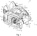
Fig. 1 is a perspective view showing a first embodiment of the brake caliper. -
Fig. 2 is across sectional view showing the first embodiment of the brake caliper. -
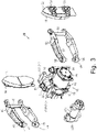
Fig. 3 is an exploded perspective view showing the first embodiment of the brake caliper. -
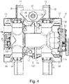
Fig. 4 is a back view showing the first embodiment of the brake caliper. -
Fig. 5 is an exploded perspective view showing a bracket, a coupling pin, and a body of the first embodiment of the brake caliper. -
Fig. 6 is a longitudinal sectional view showing the bracket, coupling pin and body of the first embodiment of the brake caliper. -
Fig. 7 is a longitudinal sectional view showing a friction applying unit of a second embodiment of the brake caliper. -
Fig. 8 is a longitudinal sectional view showing a friction applying unit of a third embodiment of the brake caliper. -
Fig. 9 is a longitudinal sectional view showing a friction applying unit of a fourth embodiment of the brake caliper. -
Fig. 10 is a longitudinal sectional view showing a friction applying unit of a fifth embodiment of the brake caliper. -
Fig. 11 is a longitudinal sectional view showing a friction applying unit of a sixth embodiment of the brake caliper. - With reference to
Figs. 1 to 6 , a first embodiment of a brake caliper will now be described. - As shown in
Figs. 1 and2 , abrake caliper 20 is mounted to a bogie (not shown) of a railway vehicle and configured to apply a braking force to a wheel of the bogie by pressingbrake pads 12 against a disc 11 (seeFig. 2 ) rotating integrally with an axle rotating the wheel. Thebrake caliper 20 and thedisc 11 together constitute a disc brake device. - The
brake caliper 20 includes a bracket 21 (seeFig. 1 ) mounted to the bogie, abody 30 rotatably hung on thebracket 21, and a pair of left and right caliper levers 40 and 50 held by thebody 30. Thebody 30 retains the pair of left and right caliper levers 40 and 50 turnably, so that thebrake pads 12 are movable to a position where they sandwich thedisc 11 and a position where they do not sandwich thedisc 11. - The
brake caliper 20 also includes acylinder device 15 for outputting a force through compressed air fed thereto and discharged therefrom, and the force causes the left and right caliper levers 40 and 50 to sandwich thedisc 11 via thebrake pads 12. The compressed air fed to thecylinder device 15 is taken from a tank installed on the railway vehicle. Thecylinder device 15 is removably mounted to thebody 30. Here, thecylinder device 15 corresponds to an actuator. - As shown in
Fig. 5 , thebracket 21 includes afirst bracket 21A and asecond bracket 21B. Thebody 30 is disposed between thefirst bracket 21A and thesecond bracket 21B. Acoupling pin 22 penetrates through thefirst bracket 21A, thebody 30, and thesecond bracket 21B to couple together thefirst bracket 21A, thebody 30, and thesecond bracket 21B. Thebody 30 has abase portion 31 through which thecoupling pin 22 penetrates. Thebase portion 31 rotates about a rotational axis P that extends orthogonal to the axial direction of the axle of the bogie and extends along a direction in which the left and right caliper levers 40 and 50 extend (seeFig. 4 ). - The
brake caliper 20 is rotatably attached to the bogie, so that thedisc 11 andbrake pads 12 remain parallel to each other even if the bogie becomes inclined while the railway vehicle travels. With such arrangement, thebrake caliper 20 may be undesirably rotated by the vibration generated during the traveling of the railway vehicle. As a result, thebrake pads 12 may touch thedisc 11 even though no brake force is generated or no braking is applied. - To address this issue, as shown in
Figs. 5 and6 , thebrake caliper 20 includes afriction applying unit 60 for increasing the frictional force resulting from the relative movement between thebracket 21 and thebody 30 as thebody 30 rotates. Thefriction applying unit 60 is provided in thesecond bracket 21B. Thefriction applying unit 60 is penetrated by thecoupling pin 22 and configured to, as thebody 30 and thesecond bracket 21B rotate relative to each other, generate sliding friction at the contact surface of thebody 30, in the axial direction, surrounding thecoupling pin 22. Thefriction applying unit 60 serves as a rotation restraining unit for restraining the rotation of thecoupling pin 22. Thefriction applying unit 60 includes afriction ring 61, which is a pressing member, for generating a frictional force when pressed against thebody 30. Thefriction ring 61 is penetrated by thecoupling pin 22. Thefriction applying unit 60 includes aspring 62, which is an energizing member, for generating a frictional force by energizing thefriction ring 61. Thespring 62 includes three disc springs. Alternatively, thespring 62 may include one, two or four or more disc springs, and the number of disc springs may be determined by a required energizing force. Thespring 62 is penetrated by thecoupling pin 22. - The
bracket 21 retain thecoupling pin 22 at the respective ends thereof. In other words, thefirst bracket 21A retains afirst end portion 22A of thecoupling pin 22, and thesecond bracket 21B retains asecond end portion 22B of thecoupling pin 22. Thefirst end portion 22A of thecoupling pin 22 has a greater diameter than thesecond end portion 22B opposite thefirst end portion 22A. Accordingly, thecoupling pin 22 is inserted into thebody 30 from the side facing thefirst bracket 21A. Thefirst end portion 22A of thecoupling pin 22 is press-fit into thefirst bracket 21A. Thecoupling pin 22 is inserted into thesecond bracket 21B and fixedly secured by abolt 26. Aring 25 is sandwiched between thecoupling pin 22 and the head of thebolt 26. Afirst bushing 23 is attached to a portion of thebody 30 that touches thefirst bracket 21A. Thefirst bushing 23 is divided into a planar portion shaped like a disc and a tubular portion shaped like a cylinder. The planar portion of thefirst bushing 23 touches thefirst bracket 21A. Thefirst bushing 23 is made of a softer material than thefirst bracket 21A. Asecond busing 24 is attached to a portion of thebody 30 that touches thesecond bracket 21B and thefriction ring 61. Thesecond bushing 24 is divided into a planar portion shaped like a disc and a tubular portion shaped like a cylinder. The planar portion of thesecond bushing 24 touches thesecond bracket 21B and thefriction ring 61. Thesecond bushing 24 is made of a softer material than thesecond bracket 21 B and thefriction ring 61. Thesecond bushing 24 corresponds to a contact member. - As the
spring 62 of thefriction applying unit 60 energizes thebody 30, thesecond bracket 21B is energized in such a direction that thesecond bracket 21B separates away from thebase portion 31 of thebody 30. As a result, thecoupling pin 22 as well as thesecond bracket 21B is pulled, so that thefirst bracket 21A fixedly attached to thefirst end portion 22A of thecoupling pin 22 is pressed against thebase portion 31 of thebody 30. Thefriction applying unit 60 thus generates a frictional force at the contact surface between thebody 30 and thesecond bracket 21B and also generates a frictional force at the contact surface between thefirst bracket 21A and thebody 30. If thebody 30 attempts to rotate relative to thebracket 21, sliding friction is generated between thefriction ring 61 and thesecond bushing 24, thereby restraining the rotation. - As shown in
Fig. 5 , thebody 30 includes afirst support portion 32 that extends from below thebase portion 31 toward the left and right caliper levers 40 and 50 to support the left and right caliper levers 40 and 50. Thebody 30 also includes asecond support portion 33 that extends from the center of thefirst support portion 32 toward the rear side in the longitudinal direction of the left and right caliper levers 40 and 50 to support thecylinder device 15. Thesecond support portion 33 is a plate-shaped member. Thebase portion 31, thefirst support portion 32, and thesecond support portion 33 of thebody 30 are formed as a single unit body. When the bogie is tilted in the axial direction of the axle, thebody 30 turns about the rotational axis P. This enables thebrake pads 12 to always remain parallel to thedisc 11. - A
left support portion 32A supporting theleft caliper lever 40 is provided on the left portion of thefirst support portion 32. Aleft rotation pin 35 penetrates theleft support portion 32A to rotatably support theleft caliper lever 40. Theleft rotation pin 35 is rotatable relative to theleft support portion 32A. Anoperation lever 35A is fixedly attached to theleft rotation pin 35 and is operated by a driving force from thecylinder device 15. Aright support portion 32B supporting theright caliper lever 50 is provided on the right portion of thefirst support portion 32. Right rotation pins 36 penetrate through upper and lower portions of theright support portion 32B respectively to rotatably support theright caliper lever 50. The right rotation pins 36 are rotatable relative to theright support portion 32B. - As shown in
Fig. 3 , theleft caliper lever 40 includes a pair of leftupper lever 47 and a leftlower lever 48. The left upper andlower levers left rotation pin 35. At the tip end portion of theleft caliper lever 40, apad attachment member 42 is connected via two pad rotation pins 43. To thepad attachment member 42, thebrake pad 12 is attached. The pad rotation pins 43 are rotatable relative to the left upper andlower levers pad attachment member 42. The left upper andlower levers lever coupling pin 46. - The
right caliper lever 50 includes a pair of a rightupper lever 57 and a rightlower lever 58. The right upper andlower levers right rotation pin 36. At the tip end portion of theright caliper lever 50, apad attachment member 52 is connected via two pad rotation pins 53. To thepad attachment member 52, thebrake pad 12 is attached. The pad rotation pins 53 are rotatable relative to the right upper andlower levers pad attachment member 52. The right upper andlower levers lever coupling pin 56. - As shown in
Fig. 2 , thecylinder device 15 is mounted to thesecond support portion 33 of thebody 30. Thecylinder device 15 includes aservice brake cylinder 70 and aparking brake cylinder 80. Theservice brake cylinder 70 and theparking brake cylinder 80 are mounted to surfaces of thesecond support portion 33 that are perpendicular to the axle. Theservice brake cylinder 70 is mounted to the left-side surface of thesecond support portion 33 of thebody 30. Theparking brake cylinder 80 is mounted to the right-side surface of thesecond support portion 33 of thebody 30. This means that the service andparking brake cylinders second support portion 33 of thebody 30. The surfaces of thesecond support portion 33 to which the service andparking brake cylinders brake pads 12. - As shown in
Fig. 3 , the service andparking brake cylinders second support portion 33 with four bolts. The service andparking brake cylinders second support portion 33 at different positions. Therefore, the service andparking brake cylinders second support portion 33 independently from each other. - As shown in
Fig. 2 , thesecond support portion 33 of thebody 30 has anopening 33A formed in the middle thereof. Theopening 33A is elongated in the longitudinal direction of the left and right caliper levers 40 and 50. With such a design, in mounting and removing the service andparking brake cylinders opening 33A in the longitudinal direction of the left and right caliper levers 40 and 50. - The
service brake cylinder 70 can be removed from the left-side surface of thesecond support portion 33 of thebody 30 by taking off bolts. Theparking brake cylinder 80 can be removed from the right-side surface of thesecond support portion 33 of thebody 30 by taking off the bolts. Thegap adjustment device 100 can be removed from the left and right caliper levers 40 and 50 by taking offbolts cylinder device 15 and thegap adjustment device 100 can be readily removed and mounted for inspection and replacement. Any number of bolts may be used to fix thecylinder device 15. - The
service brake cylinder 70 includes a first cylinder chamber 71, afirst piston 72, afirst rod 73, and afirst spring 74. Thefirst piston 72 moves within the first cylinder chamber 71. Thefirst rod 73 is fixed to thefirst piston 72 and projects from the first cylinder chamber 71. Thefirst spring 74 energizes thefirst piston 72 in such a direction that thefirst rod 73 is housed in the first cylinder chamber 71. Afirst space 75 is defined in the first cylinder chamber 71 as the space not including thefirst spring 74. Theservice brake cylinder 70 includes afirst feeding port 76 for feeding compressed air into thefirst space 75 within the first cylinder chamber 71 (seeFig. 3 ). Thefirst feeding port 76 is provided outside the first cylinder chamber 71. When the compressed air is fed into thefirst space 75 within the first cylinder chamber 71 of theservice brake cylinder 70, thefirst piston 72 is pushed such that thefirst rod 73 projects. When the compressed air is discharged from thefirst space 75 within the first cylinder chamber 71 of theservice brake cylinder 70, thefirst spring 74 pushes thefirst piston 72 so that thefirst rod 73 is accommodated in the first cylinder chamber 71. Thefirst rod 73 corresponds to an output rod of theservice brake cylinder 70. The first cylinder chamber 71 corresponds to a casing of theservice brake cylinder 70. - The
parking brake cylinder 80 includes a second cylinder chamber 81, asecond piston 82, asecond rod 83, and asecond spring 84. Thesecond piston 82 moves within the second cylinder chamber 81. Thesecond rod 83 is fixed to thesecond piston 82 and projects from the second cylinder chamber 81 and extends into the first cylinder chamber 71. Thesecond spring 84 energizes thesecond piston 82 in such a direction that thesecond rod 83 projects from the second cylinder chamber 81. Asecond space 85 is defined in the second cylinder chamber 81 as the space not including thesecond spring 84. Theparking brake cylinder 80 includes a second feeding port 86 (seeFig. 3 ) for feeding compressed air into thesecond space 85 within the second cylinder chamber 81. Thesecond feeding port 86 is provided outside the second cylinder chamber 81. When the compressed air is fed into thesecond space 85 within the second cylinder chamber 81 of theparking brake cylinder 80, thesecond piston 82 is pushed such that thesecond rod 83 is accommodated into the second cylinder chamber 81. When the compressed air is discharged from thesecond space 85 in the second cylinder chamber 81 of theparking brake cylinder 80, thesecond spring 84 pushes thesecond piston 82, so that thesecond rod 83 projects from the second cylinder chamber 81 and enters the first cylinder chamber 71. As a result, thesecond rod 83 pushes thefirst piston 72, so that thefirst rod 73 projects outside. Thesecond rod 83 corresponds to an output shaft of theparking brake cylinder 80. The second cylinder chamber 81 corresponds to a casing of theparking brake cylinder 80. - The first cylinder chamber 71 includes a first projecting
portion 71A that projects into theopening 33A. The second cylinder chamber 81 includes a second projectingportion 81A that projects into theopening 33A. The second projectingportion 81A is penetrated by thesecond rod 83. The first projectingportion 71A is fitted around the second projectingportion 81A. With such arrangement, thefirst rod 73 of theservice brake cylinder 70 and thesecond rod 83 of theparking brake cylinder 80 are positioned coaxially, and the output of theparking brake cylinder 80 is transmitted to theservice brake cylinder 70. - A
rotatable roller 35B is attached to the tip end of theoperation lever 35A. Thefirst rod 73 of thecylinder device 15 has a receivingportion 73A provided in the tip end thereof. The receivingportion 73A is a through-hole for receiving therein theroller 35B while touching theroller 35B. The receivingportion 73A is configured to transmit the driving force from thefirst rod 73 to theoperation lever 35A, while absorbing the lag between the linear movement of thefirst rod 73 and the rotational movement of theoperation lever 35A. - As shown in
Figs. 1 and2 , thebrake caliper 20 includes thegap adjustment device 100 for adjusting the gaps between thebrake pads 12 and thedisc 11. Thegap adjustment device 100 includes agap adjuster 101 for adjusting the gaps and agap outputting unit 90 for outputting a gap to thegap adjuster 101. Thegap outputting unit 90 includes a pullingunit 91 and awire 96. The pullingunit 91 is configured to pull thewire 96 to an extent determined by the amount of the movement of thefirst rod 73 of thecylinder device 15. Thegap adjuster 101 connects between the base end portion of theleft caliper lever 40 and the base end portion of theright caliper lever 50. Theleft caliper lever 40 and thegap adjuster 101 are rotatably coupled with each other with a pair of upper andlower bolts 45. Theright caliper lever 50 and thegap adjuster 101 are rotatably coupled with each other with a pair of upper andlower bolts 55. Theleft caliper lever 40 and thegap adjuster 101 rotate about a rotational axis 44, and theright caliper lever 50 and thegap adjuster 101 rotate about arotational axis 54. - The
gap adjustment device 100 adjusts the distance between the base end portion of theleft caliper lever 40 and the base end portion of theright caliper lever 50 to adjust the gaps between thebrake pads 12 and thedisc 11. As thebrake pads 12 wear off, the gap grows between thebrake pads 12 and thedisc 11. To deal with this issue, thegap adjustment device 100 increases the distance between the base end portion of theleft caliper lever 40 and the base end portion of theright caliper lever 50, thereby reducing the distance between thebrake pads 12 and thedisc 11. - In the
gap adjustment device 100, the pullingunit 91 pulls thewire 96 if thefirst rod 73 moves by a predetermined amount or more. In other words, if thefirst rod 73 protrudes and the amount of the protrusion reaches a predetermined value, thefirst rod 73 touches the pullingunit 91, as a result of which the pullingunit 91 rotates and accordingly pulls thewire 96. - As shown in
Fig. 1 , thegap adjuster 101 includes afirst casing 121 and asecond casing 122. Thefirst casing 121 connects between the respective base end portions of the left upper andlower levers first casing 121 is rotatably coupled with the left upper andlower levers bolts 45. Thesecond casing 122 connects between the respective base end portions of the right upper andlower levers second casing 122 is rotatably coupled with the right upper andlower levers bolts 55. - As shown in
Fig. 2 , thefirst casing 121 includes anextension portion 121A having a cylindrical shape and extending toward thesecond casing 122. Apolygonal rod 123 shaped like a polygonal column is fixed to thefirst casing 121. Thepolygonal rod 123 extends in the direction in which theextension portion 121A of thefirst casing 121 extends. - The tip end portion of the
polygonal rod 123 protrudes out of thefirst casing 121. The tip end portion of thepolygonal rod 123 includes ahexagonal portion 123B shaped like a hexagonal column. Thehexagonal portion 123B of thepolygonal rod 123 can be manually rotated to adjust the gaps between thebrake pads 12 and thedisc 11. - A
cylindrical screw shaft 124 is fixed to thesecond casing 122 and extends toward thefirst casing 121. Thescrew shaft 124 has acylindrical space 124A formed therein. Thespace 124A is open at thefirst casing 121 side only. Thespace 124A in thescrew shaft 124 receives thepolygonal rod 123. Thescrew shaft 124 has external threads 124B on the outer surface thereof excluding the portion fixed to thesecond casing 122. Thescrew shaft 124 is supported by asupport spring 122A. The tip end portion of thescrew shaft 124 has ahexagonal portion 124C shaped like a hexagonal column. Thehexagonal portion 124C of thescrew shaft 124 can be manually rotated to adjust the gaps between thebrake pads 12 and thedisc 11. With the above arrangement, the gap adjustment is accessible from both sides of thegap adjuster 101. The gaps thus can be adjusted by a large amount at one time, resulting in increased efficiency and ease of the adjustment during maintenance work. - An
adjustment nut 125 shaped like a cylinder is provided on the outer periphery of thescrew shaft 124. The inner wall of theadjustment nut 125 partially hasinternal threads 125A that are configured to engage with the external threads 124B of thescrew shaft 124. Theadjustment nut 125 rotates relative to thescrew shaft 124 while engaging with the external threads 124B of thescrew shaft 124. Specifically, as thescrew shaft 124 moves away from thepolygonal rod 123, theadjustment nut 125 is rotated by the external threads 124B of thescrew shaft 124 and theinternal threads 125A of theadjustment nut 125. - The
adjustment nut 125 is positioned between theextension portion 121A of thefirst casing 121 and thescrew shaft 124. The outer periphery of theadjustment nut 125 has aridge 125B provided thereon. Theridge 125B projects toward the inner wall of theextension portion 121A of thefirst casing 121. Between theadjustment nut 125 and theextension portion 121A of thefirst casing 121, ananti-vibration spring 126 is provided and energizes theridge 125B toward thefirst casing 121 in the axial direction of theadjustment nut 125. Theanti-vibration spring 126 is formed of a coil spring and is provided on the outer periphery of theadjustment nut 125. Since theridge 125B of theadjustment nut 125 is energized by theanti-vibration spring 126, this can reduce the effect of vibration. Acontact clutch 127 is provided between theadjustment nut 125 and theextension portion 121A of thefirst casing 121. When theridge 125B is pushed toward theleft caliper lever 40 in the axial direction, the contact clutch 127 contacts the surface of theridge 125B that is perpendicular to the axial direction to control rotation of theadjustment nut 125. Acylindrical cover 128 covering thefirst casing 121 is fixedly attached to thesecond casing 122. - A
wire attachment portion 130 is attached to a portion of thescrew shaft 124 near thefirst casing 121. To thewire attachment portion 130, thewire 96 is connected. A one-way clutch 131 is provided between theadjustment nut 125 and theextension portion 121A of thefirst casing 121. Thewire attachment portion 130 is fixedly attached to the one-way clutch 131. The one-way clutch 131 and thewire attachment portion 130 can integrally rotate. The one-way clutch 131 permits theadjustment nut 125 to rotate such that thegap adjuster 101 is elongated but prevents theadjustment nut 125 from rotating such that thegap adjuster 101 is shortened. Aspring 132 is attached to the one-way clutch 131. If thewire 96 is pulled by the pullingunit 91, the one-way clutch 131 and thewire attachment portion 130 rotate clockwise as seen from the left side, so that thespring 132 is compressed. If thewire 96 is released from being pulled, the energizing force from thespring 132 rotates the one-way clutch 131 and thewire attachment portion 130, as well as theadjustment nut 125, in a reversed direction (anti-clockwise), elongating thegap adjuster 101. - Next, the operation of the
brake caliper 20 will now be described. With additional reference toFig. 2 , a description is given of the operation of thebrake caliper 20 and thegap adjustment device 100 performed before thebrake pads 12 are worn. - While the railway vehicle travels, the traveling causing the railway vehicle to vibrate and the vibration causes the wheels and bogies to move relative to each other in the width direction (the thickness direction of the disc 11), the vertical direction and the front-rear direction of the railway vehicle. If the wheels and bogies move relative to each other, the
body 30 supported on thebracket 21, which is attached to the bogie, is prevented by thefriction applying unit 60 from rotating around thecoupling pin 22 relative to thebracket 21. Thefriction applying unit 60 generates a frictional force at the contact surface between thebody 30 and thesecond bracket 21B, and also generates a frictional force at the contact surface between thefirst bracket 21A and thebody 30. Accordingly, thebody 30 hardly rotates relative to thebracket 21 even if the railway vehicle vibrates while traveling. Here, if thebrake pads 12 are pushed by thedisc 11 and thebody 30 resultantly receives a force from thedisc 11 via the left orright caliper lever body 30 rotates around thecoupling pin 22. In other words, thefriction applying unit 60 is configured such that it can prevent thebody 30 from rotating around thecoupling pin 22 when the vibration is generated, while allowing thebody 30 to rotate around thecoupling pin 22 when thedisc 11 touches thebrake pads 12. - As shown in
Fig. 2 , thebrake caliper 20 is configured such that compressed air is fed into thefirst space 75 in theservice brake cylinder 70 of thecylinder device 15 to actuate the service brake. Thefirst rod 73 of theservice brake cylinder 70 moves in such a direction that it projects from the first cylinder chamber 71 along with thefirst piston 72, thereby driving theoperation lever 35A clockwise via theroller 35B. Here, if thebrake pads 12 have not worn off very much and the amount of movement (protrusion) of thefirst rod 73 is thus less than a predetermined value, thefirst rod 73 does not touch the pullingunit 91. - As the
first rod 73 moves in such a direction that it projects from the first cylinder chamber 71, theoperation lever 35A rotates clockwise along with theleft rotation pin 35. The clockwise rotation of theleft rotation pin 35 causes theleft caliper lever 40 to rotate about the rotational axis 44 in such a direction that theleft brake pad 12 contacts thedisc 11, as a result of which theleft brake pad 12 contacts thedisc 11. - After the
left brake pad 12 contacts thedisc 11, theleft caliper lever 40 rotates clockwise about thepad rotation pin 43. When theleft caliper lever 40 rotates about thepad rotation pin 43, theright caliper lever 50 rotates counterclockwise about theright rotation pin 36 via the rotational axis 44, thegap adjuster 101 and therotational axis 54, as a result of which theright brake pad 12 contacts thedisc 11. - When the compressed air is discharged from the
second space 85 within theparking brake cylinder 80 and thesecond rod 83 projects from the second cylinder chamber 81, thesecond rod 83 pushes thefirst piston 72 and thefirst rod 73, resulting in the same operation as when thefirst rod 73 projects from the first cylinder chamber 71. - The following now describes how the
brake caliper 20 and thegap adjustment device 100 operate with thebrake pads 12 having worn out. When thebrake pads 12 are worn out, theservice brake cylinder 70 operates in the same manner with compressed air fed thereto. The amount of movement of thefirst rod 73 increases as the amount of wear of thebrake pads 12 increases. If the amount of wear of thebrake pads 12 increases to such an extent that the amount of movement of thefirst rod 73 becomes equal to or greater than a predetermined value, thegap adjustment device 100 comes into operation. Specifically, thegap adjuster 101 is elongated to shorten the gaps between thebrake pads 12 and thedisc 11. - If the
first rod 73 has moved by a predetermined amount or more, the tip end portion of thefirst rod 73 touches the pullingunit 91 and the pullingunit 91 rotates, as a result of which thewire 96 is pulled. If thewire 96 is pulled, thewire attachment portion 130 rotates clockwise together with the one-way clutch 131. Here, if thefirst rod 73 has moved by a predetermined amount or more, this means that the gaps between thebrake pads 12 and thedisc 11 are equal to or greater than a prescribed value. - Subsequently, in the
brake caliper 20, when theleft brake pad 12 and theright brake pad 12 sandwich thedisc 11 to generate a compressive force in thegap adjuster 101, thescrew shaft 124 tends to rotate theadjustment nut 125 in the direction for shortening. Here, the rotation of theadjustment nut 125 is controlled by the frictional force between thecontact clutch 127 and theridge 125B of theadjustment nut 125 and by the one-way clutch 131. Therefore, thescrew shaft 124 does not move in the direction for shortening, and the sandwiching force of thebrake caliper 20 is maintained, thus generating a braking force. - Subsequently, in the
brake caliper 20, when feeding of the compressed air to theservice brake cylinder 70 is stopped to release the brake, thefirst rod 73 returns to the first cylinder chamber 71. This means that thefirst rod 73 no longer touches the pullingunit 91 and that the pullingunit 91 no longer pulls thewire 96. If thewire 96 is released from being pulled, the energizing force from thespring 132 rotates the one-way clutch 131 andwire attachment portion 130, as well as theadjustment nut 125, in a reversed direction (anti-clockwise). Here, the one-way clutch 131 does not rotate in the direction for elongation. The one-way clutch 131 thus rotates anti-clockwise together with theadjustment nut 125. This enlarges the entire length of thegap adjuster 101, resulting in a larger distance between the base end portion of theleft caliper lever 40 and the base end portion of theright caliper lever 50 and smaller gaps between thebrake pads 12 and thedisc 11. - Advantageous effects of the first embodiment will be now described.
- (1) A frictional force is generated against the relative rotation between the
body 30 and thebracket 21, thereby making it difficult for thebody 30 to rotate relative to thebracket 21. This can prevent unintended contact between thebrake pads 12 and thedisc 11 when the brake is not in operation. In addition, sliding friction is generated around thecoupling pin 22 at the contact surface of thecoupling pin 22 in the axial direction and prevents rotation. Accordingly, the friction can be applied in a more stabilized manner than in a case where the friction is applied only at part of thebody 30 orbracket 21 around thecoupling pin 22. - (2) As enclosed in the
bracket 21, thefriction applying unit 60 can be provided without affecting the constitution of thebody 30. Thebracket 21 can be configured in any manner as long as it can be fixedly attached to the bogie. Accordingly, an additional constituent part for allowing the frictional applyingunit 60 to be arranged can be more easily provided in thebracket 21 than in thebody 30. - (3) Since the
spring 62 energizes thefriction ring 61, a force can be reliably produced against the relative rotation between thebody 30 and thebracket 21. - (4) If the
second bushing 24 is worn out, a desired frictional force can be restored by replacing thesecond bushing 24 with a new one. This facilitates the maintenance work when compared with the case where thebody 30,bracket 21 andcoupling pin 22 are replaced with their counterparts. - (5) The
second end portion 22B of thecoupling pin 22 has a smaller diameter than thefirst end portion 22A. With such a design, the weight of thecoupling pin 22 can be reduced. As thespring 62 fittingly surrounds the outer periphery of thesecond end portion 22B, thespring 62 is allowed to have a smaller diameter than in a case where thespring 62 is provided around thefirst end portion 22A. Thefriction applying unit 60 can achieve a reduced size. - With reference to
Fig. 7 , a second embodiment of the brake caliper will now be described. The second embodiment is different from the first embodiment in that thefriction applying unit 60 of the brake caliper is arranged near thefirst end portion 22A of thecoupling pin 22. The following description will be focused on the differences from the first embodiment. - As shown in
Fig. 7 , thefriction applying unit 60 is enclosed within thefirst bracket 21A. Thefriction applying unit 60 is penetrated by thecoupling pin 22 and configured to, as thebody 30 and thefirst bracket 21A rotate relative to each other, generate sliding friction at the contact surface of thebody 30 in the axial direction, surrounding thecoupling pin 22. Thefriction applying unit 60 serves as a rotation restraining unit for restraining the rotation of thecoupling pin 22. Thefriction applying unit 60 includes thefriction ring 61, which is a pressing member, for generating a frictional force when pressed against thebody 30. Thefriction ring 61 is penetrated by thecoupling pin 22. Thefriction applying unit 60 includes thespring 62, which is an energizing member, for generating a frictional force by energizing thefriction ring 61. Thespring 62 includes three disc springs. Alternatively, thespring 62 may include one, two or four or more disc springs, and the number of disc springs may be determined by a required energizing force. Thespring 62 is penetrated by thecoupling pin 22. - The
first end portion 22A of thecoupling pin 22 has a smaller diameter than thesecond end portion 22B opposite thefirst end portion 22A. Accordingly, thecoupling pin 22 is inserted into thebody 30 from the side facing thesecond bracket 21B. Thecoupling pin 22 is then inserted into thefirst bracket 21A and fixedly secured by thebolt 26 with thefirst bracket 21A and thering 25 being placed therebetween. Thefirst bushing 23 is attached to the portion of thebody 30 that touches thefirst bracket 21A. Thesecond end portion 22B of thecoupling pin 22 is press-fit into thesecond bracket 21B. Thesecond busing 24 is attached to the portion of thebody 30 that touches thesecond bracket 21B and thefriction ring 61. Thefirst bushing 23 corresponds to a contact member. - As the
spring 62 of thefriction applying unit 60 energizes thebody 30, thefirst bracket 21A is energized in such a direction that thefirst bracket 21A separates away from thebase portion 31 of thebody 30. As a result, thecoupling pin 22, as well as thefirst bracket 21A, is pulled toward thefirst bracket 21A, so that thesecond bracket 21B fixedly attached to thesecond end portion 22B of thecoupling pin 22 is pressed against thebase portion 31 of thebody 30. Thefriction applying unit 60 thus generates a frictional force at the contact surface between thebody 30 and thefirst bracket 21A and also at the contact surface between thesecond bracket 21B and thebody 30. If thebody 30 attempts to rotate relative to thebracket 21, sliding friction is generated between thefriction ring 61 and thefirst bushing 23, thereby restraining the rotation. - Advantageous effects of the second embodiment will be now described. The following advantageous effects are obtained in addition to the advantageous effects (1) to (3) of the first embodiment.
- (6) If the
first bushing 23 is worn out, a desired frictional force can be restored by replacing thefirst bushing 23 with a new one. This facilitates the maintenance work when compared with the case where thebody 30,bracket 21 andcoupling pin 22 are replaced with their counterparts. - (7) Since the
first end portion 22A of thecoupling pin 22 has a smaller diameter than thesecond end portion 22B, the weight can be reduced. As thespring 62 fittingly surrounds the outer periphery of thefirst end portion 22A, thespring 62 is allowed to have a smaller diameter than in a case where thespring 62 is provided around thesecond end portion 22B. Thefriction applying unit 60 can achieve a reduced size. - With reference to
Fig. 8 , a third embodiment of the brake caliper will now be described. The third embodiment is different from the first embodiment in that thefriction applying unit 60 is arranged between thebody 30 and the coupling pin. The following description will be focused on the differences from the first embodiment. - As shown in
Fig. 8 , afirst coupling pin 222A is provided between thebody 30 and thefirst bracket 21A. Between thebody 30 and thesecond bracket 21B, asecond coupling pin 222B is provided. The first and second coupling pins 222A and 222B constitute acoupling pin 222. Thebrake caliper 20 includes thefriction applying unit 60 for generating sliding friction at the contact surface of thesecond coupling pin 222B in the axial direction against the relative rotation between thebody 30 and thesecond coupling pin 222B. Thefriction applying unit 60 is provided in thebody 30. Thefriction applying unit 60 generates sliding friction at the contact surface of thesecond coupling pin 222B that defines thesecond coupling pine 222B in the axial direction and that is on the axis. Thefriction applying unit 60 serves as a rotation restraining unit for restraining the rotation of thesecond coupling pin 222B. Thefriction applying unit 60 includes thefriction ring 61, which is a pressing member, for generating a frictional force when pressed against thesecond coupling pin 222B. Thefriction applying unit 60 includes thespring 62, which is an energizing member, for generating a frictional force by energizing thefriction ring 61. Thespring 62 includes three disc springs. Alternatively, thespring 62 may include one, two or four or more disc springs, and the number of disc springs may be determined by a required energizing force. - The
first coupling pin 222A is inserted into thefirst bracket 21A and fixedly secured by thefirst bracket 21A and abolt 26. Thesecond coupling pin 222B is inserted into thesecond bracket 21B and fixedly secured by abolt 26 with thesecond bracket 21B and thering 25 being placed therebetween. Thefirst bushing 23 is attached to the portion of thebody 30 that touches thefirst bracket 21A. Thesecond bushing 24 is attached to the portion of thebody 30 that touches thesecond bracket 21B. - Since the
spring 62 of thefriction applying unit 60 energizes thefriction ring 61, thefriction ring 61 is pressed against thesecond coupling pin 222B. This can generate sliding friction between thefriction ring 61 and thesecond coupling pin 222B. If thebody 30 attempts to rotate relative to thesecond bracket 21B, the sliding friction is generated between thefriction ring 61 and thesecond coupling pin 222B, thereby restraining the rotation. - Advantageous effects of the third embodiment will be now described. The following advantageous effects are obtained in addition to the advantageous effect (3) of the first embodiment.
- (8) A frictional force is generated against the relative rotation between the
body 30 and thesecond bracket 21B, thereby making it difficult for thebody 30 to rotate relative to thesecond bracket 21B. This can prevent unintended contact between thebrake pads 12 and thedisc 11 when the brake is not in operation. In addition, since sliding friction is generated at the contact surface of thecoupling pin 222 in the axial direction and prevents the rotation, friction can be applied in a more stabilized manner than in a case where friction is applied only at part of the contact surface of thecoupling pin 222 in the axial direction. - With reference to
Fig. 9 , a fourth embodiment of the brake caliper will now be described. The fourth embodiment is different from the third embodiment in that thefriction applying unit 60 is arranged between thebody 30 and afirst coupling pin 222A. The following description will be focused on the differences from the third embodiment. - As shown in
Fig. 9 , thebrake caliper 20 includes thefriction applying unit 60 for generating sliding friction at the contact surface of thefirst coupling pin 222A in the axial direction against the relative rotation between thebody 30 and thefirst coupling pin 222A. Thefriction applying unit 60 is enclosed within thebody 30. Thefriction applying unit 60 generates sliding friction at the contact surface of thefirst coupling pin 222A that defines thefirst coupling pin 222A in the axial direction and that is on the axis. Thefriction applying unit 60 serves as a rotation restraining unit for restraining the rotation of thefirst coupling pin 222A. Thefriction applying unit 60 includes thefriction ring 61, which is a pressing member, for generating a frictional force when pressed against thefirst coupling pin 222A. Thefriction applying unit 60 includes thespring 62, which is an energizing member, for generating a frictional force by energizing thefriction ring 61. Thespring 62 includes three disc springs. Alternatively, thespring 62 may include one, two or four or more disc springs, and the number of disc springs may be determined by a required energizing force. - Since the
spring 62 of thefriction applying unit 60 energizes thefriction ring 61, thefriction ring 61 is pressed against thefirst coupling pin 222A. This can generate sliding friction between thefriction ring 61 and thefirst coupling pin 222A. If thebody 30 attempts to rotate relative to thefirst bracket 21A, sliding friction is generated between thefriction ring 61 and thefirst coupling pin 222A, thereby restraining the rotation. - Advantageous effects of the fourth embodiment will be now described. The following advantageous effects are obtained in addition to the advantageous effect (3) of the first embodiment.
- (9) A frictional force is generated against the relative rotation between the
body 30 and thefirst bracket 21A, thereby making it difficult for thebody 30 to rotate relative to thefirst bracket 21A. This can prevent unintended contact between thebrake pads 12 and thedisc 11 when the brake is not in operation. In addition, since sliding friction is generated at the contact surface of thefirst coupling pin 222A in the axial direction and prevents the rotation, friction can be applied in a more stabilized manner than in a case where friction is applied only at part of the contact surface of thecoupling pin 222 in the axial direction. - With reference to
Fig. 10 , a fifth embodiment of the brake caliper will now be described. The fifth embodiment is different from the first embodiment in that thefriction applying unit 60 is arranged between thecoupling pin 22 and thesecond bracket 21B. The following description will be focused on the differences from the first embodiment. - As shown in
Fig. 10 , thebrake caliper 20 includes thefriction applying unit 60 for generating sliding friction at the contact surface of thecoupling pin 22 in the axial direction against the relative rotation between thecoupling pin 22 and thesecond bracket 21B. Thefriction applying unit 60 is enclosed within thesecond bracket 21B. Thefriction applying unit 60 generates sliding friction at the contact surface of thecoupling pin 22 that defines thecoupling pin 22 in the axial direction and that is on the axis. Thefriction applying unit 60 serves as a rotation restraining unit for restraining the rotation of thecoupling pin 22. Thefriction applying unit 60 includes thefriction ring 61, which is a pressing member, for generating a frictional force when pressed against thecoupling pin 22. Thefriction applying unit 60 includes aspring 62, which is an energizing member, for generating a frictional force by energizing thefriction ring 61. Thespring 62 includes three disc springs. Alternatively, thespring 62 may include one, two or four or more disc springs, and the number of disc springs may be determined by a required energizing force. - The
first end portion 22A of thecoupling pin 22 has a greater diameter than thesecond end portion 22B opposite thefirst end portion 22A. Accordingly, thecoupling pin 22 is inserted into thebody 30 from the side facing thefirst bracket 21A. Thefirst end portion 22A of thecoupling pin 22 is press-fit into thefirst bracket 21A. Thesecond end portion 22B of thecoupling pin 22 is press-fit into thesecond bracket 21B. In other words, after thespring 62 and thefriction ring 61 are inserted into thesecond bracket 21B, thesecond end portion 22B of thecoupling pin 22 is press-fit into thesecond bracket 21B. In this way, thefriction applying unit 60 is completed. Thecoupling pin 22 is fixedly attached to thebody 30. Accordingly, as thebody 30 rotates relative to thesecond bracket 21B, sliding friction is generated between thesecond end portion 22B of thecoupling pin 22 and thesecond bracket 21B. - Advantageous effects of the fifth embodiment will be now described. The following advantageous effects are obtained in addition to the advantageous effects (2) and (3) of the first embodiment.
- (10) A frictional force is generated against the relative rotation between the
coupling pin 22 and thesecond bracket 21B, thereby making it difficult for thecoupling pin 22 to rotate relative to thesecond bracket 21B. This can prevent unintended contact between thebrake pads 12 and thedisc 11 while the brake is not in operation. In addition, since sliding friction is generated at the contact surface of thecoupling pin 22 in the axial direction and prevents the rotation, friction can be applied in a more stabilized manner than in a case where friction is applied only at part of the contact surface of thecoupling pin 22 in the axial direction. - With reference to
Fig. 11 , a sixth embodiment of the brake caliper will now be described. The sixth embodiment is different from the fifth embodiment in that thefriction applying unit 60 is arranged between thecoupling pin 22 and thefirst bracket 21B. The following description will be focused on the differences from the fifth embodiment. - As shown in
Fig. 11 , thebrake caliper 20 includes thefriction applying unit 60 for generating sliding friction at the contact surface of thecoupling pin 22 in the axial direction against the relative rotation between thecoupling pin 22 and thefirst bracket 21A. Thefriction applying unit 60 is enclosed within thefirst bracket 21A. Thefriction applying unit 60 generates sliding friction at the contact surface of thecoupling pin 22 that defines thecoupling pin 22 in the axial direction and that is on the axis. Thefriction applying unit 60 serves as a rotation restraining unit for restraining the rotation of thecoupling pin 22. Thefriction applying unit 60 includes thefriction ring 61, which is a pressing member, for generating a frictional force when pressed against thecoupling pin 22. Thefriction applying unit 60 includes thespring 62, which is an energizing member, for generating a frictional force by energizing thefriction ring 61. Thespring 62 includes three disc springs. Alternatively, thespring 62 may include one, two or four or more disc springs, and the number of disc springs may be determined by a required energizing force. - The
first end portion 22A of thecoupling pin 22 has a greater diameter than thesecond end portion 22B opposite thefirst end portion 22A. Accordingly, thecoupling pin 22 is inserted into thebody 30 from the side facing thefirst bracket 21A. Thefirst end portion 22A of thecoupling pin 22 is press-fit into thefirst bracket 21A. Thesecond end portion 22B of thecoupling pin 22 is press-fit into thesecond bracket 21B. In other words, after thespring 62 and thefriction ring 61 are inserted into thefirst bracket 21A, thefirst end portion 22A of thecoupling pin 22 is press-fit into thefirst bracket 21A. In this way, thefriction applying unit 60 is completed. Thecoupling pin 22 is fixedly attached to thebody 30. Accordingly, as thebody 30 rotates relative to thefirst bracket 21A, sliding friction is generated between thefirst end portion 22A of thecoupling pin 22 and thefirst bracket 21A. - Advantageous effects of the sixth embodiment will be now described. The following advantageous effects are obtained in addition to the advantageous effects (2) and (3) of the first embodiment.
- (11) A frictional force is generated against the relative rotation between the
coupling pin 22 and thefirst bracket 21A, thereby making it difficult for thecoupling pin 22 to rotate relative to thefirst bracket 21A. This can prevent unintended contact between thebrake pads 12 and thedisc 11 when the brake is not in operation. In addition, since sliding friction is generated at the contact surface of thecoupling pin 22 in the axial direction and prevents the rotation, friction can be applied in a more stabilized manner than in a case where friction is applied only at part of the contact surface of thecoupling pin 22 in the axial direction. - The foregoing embodiments can be modified as described below. The above embodiments and the following modifications can be implemented in combination to the extent where they are technically consistent with each other.
- In the first, second, fifth and sixth embodiments, the first and
second end portions coupling pin 22 have different diameters. The first andsecond end portions coupling pin 22, however, may have the same diameter. - In the first to fourth embodiments, the
bolts 26 are used to fixedly secure thecoupling pin bracket 21. Thebolts 26, however, may not be used as long as thecoupling pin bracket 21. - In the foregoing embodiments, the
first bushing 23 is provided. The embodiments of the present invention, however, may be practiced without thefirst bushing 23. In the foregoing embodiments, thesecond bushing 24 is provided. The embodiments of the present invention, however, may be practiced without thesecond bushing 24. - Although the energizing member or
spring 62 is formed by the disc springs in the above-described embodiments, other structures or mechanisms may be used instead of the disc springs as long as they can push the pressing member orfriction ring 61. For instance, the energizing member may be formed of a different type of springs such as a coil spring or an elastic member such as an O-ring. As a further alternative example, the energizing member may be constituted by a first permanent magnet and a second permanent magnet that is attached to the pressing member. Here, the first and second permanent magnets are arranged such that like poles of the first and second permanent magnets face each other. In this case, the pressing member is pushed by a repulsive force generated between the first permanent magnet and the second permanent magnet. - The foregoing embodiments may be practiced without the energizing member. The foregoing embodiments employ the
cylinder device 15 as the actuator, but may use other devices such as motor devices as the actuator. - The foregoing embodiments describe a plurality of physically separate constituent parts. They may be combined into a single part, and any one of them may be divided into a plurality of physically separate constituent parts. Irrespective of whether or not the constituent parts are integrated, they are acceptable as long as they are configured to solve the problems.
-
- 11
- disc
- 12
- brake pad
- 15
- cylinder device
- 20
- brake caliper
- 21
- bracket
- 21A
- first bracket
- 21B
- second bracket
- 22
- coupling pin
- 22A
- first end portion
- 22B
- second end portion
- 23
- first bushing
- 24
- second bushing
- 25
- ring
- 26
- bolt
- 30
- body
- 31
- base portion
- 32
- first support portion
- 33
- second support portion
- 33A
- opening
- 35
- left rotation pin
- 35A
- operation lever
- 35B
- roller
- 36
- right rotation pin
- 40
- left caliper lever
- 42
- pad attachment member
- 43
- pad rotation pin
- 44
- rotational axis
- 45
- bolt
- 46
- left lever coupling pin
- 47
- left upper lever
- 48
- left lower lever
- 50
- right caliper lever
- 52
- pad attachment member
- 53
- pad rotation pin
- 54
- rotational axis
- 55
- bolt
- 56
- right lever coupling pin
- 57
- right upper lever
- 58
- right lower lever
- 60
- friction applying unit
- 61
- friction ring serving as pressing member
- 62
- spring serving as energizing member
- 70
- service brake cylinder
- 80
- parking brake cylinder
- 90
- gap output unit
- 91
- pulling unit
- 96
- wire
- 97
- outer tube
- 100
- gap adjustment device
- 101
- gap adjuster
- 121
- first case
- 122
- second case
- 123
- polygonal rod
- 123A
- space
- 123B
- hexagonal portion
- 124
- screw shaft
- 124A
- space
- 124B
- external thread
- 124C
- hexagonal portion
- 125
- adjustment nut
- 125A
- internal thread
- 126
- anti-vibration spring
- 127
- contact clutch
- 128
- cover
- 130
- wire attachment portion
- 131
- one-way clutch
- 132
- spring
- 222
- coupling pin
- 222A
- first coupling pin
- 222B
- second coupling pin
Claims (9)
- A brake calipers (20) comprising:a pair of caliper levers (40, 50), each caliper lever (40, 50) retaining a brake pad (12);an actuator (15) for outputting a force to rotate the caliper levers (40, 50) such that the caliper levers (40, 50) press a disc (11);a body (30) retaining the caliper levers (40, 50) in a rotatable manner and retaining the actuator (15);a bracket (21) fixedly attached to a bogie;a coupling pin (22) coupling the body (30) to the bracket (21) such that the body (30) and the bracket (21) are rotatable relative to each other around a rotational axis extending in a longitudinal direction of the caliper levers (40, 50); anda rotation restraining unit (60) penetrated by the coupling pin (22), the rotation restraining unit (60) being configured to restrain rotation of the body (30) by generating sliding friction at a contact surface of the rotation restraining unit (60) where the rotation restraining unit (60) touches the body (30) or the bracket (21).
- A brake caliper (20) comprising:a pair of caliper levers (40, 50), each caliper lever (40, 50) retaining a brake pad (12);an actuator (15) for outputting a force to rotate the caliper levers (40, 50) such that the caliper levers (40, 50) press a disc (11);a body (30) retaining the caliper levers (40, 50) in a rotatable manner and retaining the actuator (15);a bracket (21) fixedly attached to a bogie;a coupling pin (22, 222) supporting the body (30) such that the body (30) is rotatable relative to the bracket (21) around a rotational axis extending in a longitudinal direction of the caliper levers (40, 50); anda rotation restraining unit (60) configured to restrain rotation of the coupling pin (22, 222) by generating sliding friction at a contact surface of the rotation restraining unit (60) where the rotation restraining unit (60) touches an end of the coupling pin (22, 222) in an axial direction.
- The brake caliper (20) of claim 1 or 2, wherein the rotation restraining unit (60) is provided in the bracket (21).
- The brake caliper (20) of any one of claims 1 to 3, wherein the rotation restraining unit (60) includes a pressing member (61) for generating the sliding friction when pressed against the bracket (21) or the body (30) and an energizing member (62) for generating a frictional force by energizing the pressing member (61).
- The brake caliper (20) of claim 4, wherein the pressing member (61) and the energizing member (62) are penetrated by the coupling pin (22).
- The brake caliper (20) of claim 4 or 5, comprising
contact members (23, 24) touching the pressing member (61), the contact members (23, 24) being made of a softer material than the pressing member (61). - The brake caliper (20) of any one of claims 4 to 6,wherein the bracket (21) retains the coupling pin 22 at respective ends thereof,wherein a first end portion (22A) of the coupling pin (22) has a smaller diameter than a second end portion (22B) opposite the first end portion (22A), andwherein the energizing member (62) fittingly surrounds an outer periphery of the first end portion (22A).
- A brake caliper (20) comprising:a pair of caliper levers (40, 50), each caliper lever (40, 50) retaining a brake pad (12);an actuator (15) for outputting a force to rotate the caliper levers (40, 50) such that the caliper levers (40, 50) press a disc (11);a body (30) retaining the caliper levers (40, 50) in a rotatable manner and retaining the actuator (15);a bracket (21) fixedly attached to a bogie;a coupling pin (22) coupling the body (30) to the bracket (21) such that the body (30) is rotatable around a rotational axis extending in a longitudinal direction of the caliper levers (40, 50); anda rotation restraining unit (60) provided in the bracket (21) and penetrated by the coupling pin (22), the rotation restraining unit (60) being configured to restrain rotation of the body (30) by generating sliding friction at a contact surface of the rotation restraining unit (60) where the rotation restraining unit (60) touches the body (30) or the bracket (21),wherein the rotation restraining unit (60) includes a pressing member (61) for generating the sliding friction when pressed against the body (30) and an energizing member (62) for generating a frictional force by energizing the pressing member (61).
- A brake caliper (20) comprising:a pair of caliper levers (40, 50), each caliper lever (40, 50) retaining a brake pad (12);an actuator (15) for outputting a force to rotate the caliper levers (40, 50) such that the caliper levers (40, 50) press a disc (11);a body (30) retaining the caliper levers (40, 50) in a rotatable manner and retaining the actuator (15);a bracket (21) fixedly attached to a bogie;a coupling pin (22) supporting the body (30) such that the body (30) is rotatable relative to the bracket (21) around a rotational axis extending in a longitudinal direction of the caliper levers (40, 50); anda rotation restraining unit (60) provided in the bracket (21), the rotation restraining unit (60) being configured to restrain rotation of the coupling pin (22) by generating sliding friction at a contact surface of the rotation restraining unit (60) where the rotation restraining unit (60) touches an end of the coupling pin (22) in an axial direction,wherein the rotation restraining unit (60) includes a pressing member (61) for generating the sliding friction when pressed against the coupling pin (22) and an energizing member (62) for generating a frictional force by energizing the pressing member (61).
Applications Claiming Priority (1)
| Application Number | Priority Date | Filing Date | Title |
|---|---|---|---|
| JP2020180841A JP7444755B2 (en) | 2020-10-28 | 2020-10-28 | brake caliper device |
Publications (2)
| Publication Number | Publication Date |
|---|---|
| EP3992485A1 true EP3992485A1 (en) | 2022-05-04 |
| EP3992485B1 EP3992485B1 (en) | 2025-06-25 |
Family
ID=77913022
Family Applications (1)
| Application Number | Title | Priority Date | Filing Date |
|---|---|---|---|
| EP21198639.3A Active EP3992485B1 (en) | 2020-10-28 | 2021-09-23 | Brake caliper |
Country Status (3)
| Country | Link |
|---|---|
| EP (1) | EP3992485B1 (en) |
| JP (1) | JP7444755B2 (en) |
| CN (1) | CN114483823B (en) |
Cited By (2)
| Publication number | Priority date | Publication date | Assignee | Title |
|---|---|---|---|---|
| EP4316944A1 (en) * | 2022-07-26 | 2024-02-07 | Nabtesco Corporation | Brake caliper device |
| DE102024121087A1 (en) * | 2024-07-24 | 2026-01-29 | Knorr-Bremse Systeme für Schienenfahrzeuge GmbH | Compact brake caliper unit with tandem brake cylinder for a rail vehicle |
Families Citing this family (1)
| Publication number | Priority date | Publication date | Assignee | Title |
|---|---|---|---|---|
| CN115158390B (en) * | 2022-07-29 | 2024-03-01 | 中国铁道科学研究院集团有限公司 | Lightweight braking clamp unit |
Citations (5)
| Publication number | Priority date | Publication date | Assignee | Title |
|---|---|---|---|---|
| DE29515260U1 (en) * | 1994-09-02 | 1996-01-04 | Knorr-Bremse Systeme für Schienenfahrzeuge GmbH, 80809 München | Brake caliper unit for disc brakes of vehicles, in particular rail vehicles |
| JP2009115214A (en) * | 2007-11-06 | 2009-05-28 | Kayaba Ind Co Ltd | Caliper brake device for vehicle |
| JP2010164183A (en) | 2009-01-19 | 2010-07-29 | Mitsubishi Heavy Ind Ltd | Disk brake device |
| WO2012123318A1 (en) * | 2011-03-17 | 2012-09-20 | Knorr-Bremse Systeme für Schienenfahrzeuge GmbH | Brake device of a rail vehicle with a brake calliper unit which is spring-loaded into the neutral position |
| US20170058977A1 (en) * | 2015-08-24 | 2017-03-02 | Nabtesco Corporation | Caliper device and disc brake device including the same |
Family Cites Families (19)
| Publication number | Priority date | Publication date | Assignee | Title |
|---|---|---|---|---|
| GB717350A (en) * | 1952-03-28 | 1954-10-27 | Automotive Prod Co Ltd | Improvements in or relating to disc brakes |
| US4019608A (en) * | 1975-05-06 | 1977-04-26 | Norman Allen Johnson | Lever actuated caliper brake |
| JPS6040904Y2 (en) * | 1978-12-20 | 1985-12-11 | トキコ株式会社 | disc brake |
| CA1221040A (en) * | 1982-12-16 | 1987-04-28 | Bert A. Gumkowski | Spring for a disc brake |
| FR2563594B1 (en) * | 1984-04-26 | 1986-07-18 | Dba | SLIDING CALIPER DISC BRAKE |
| US5547047A (en) * | 1995-01-25 | 1996-08-20 | New York Air Brake Corporation | Brake caliper shock and vibration isolation system |
| AT892U1 (en) * | 1995-09-07 | 1996-07-25 | Jenbacher Energiesysteme Ag | DISC BRAKE, ESPECIALLY FOR RAIL VEHICLES |
| AT405166B (en) * | 1996-12-19 | 1999-06-25 | Siemens Sgp Verkehrstech Gmbh | Bogie undercarriage for a rail vehicle |
| US6334514B1 (en) * | 2000-02-02 | 2002-01-01 | Shimano Inc. | Bicycle disc brake |
| JP2008196655A (en) | 2007-02-15 | 2008-08-28 | Shimonishi Giken Kogyo Kk | Tilt hinge |
| JP4939444B2 (en) * | 2008-01-09 | 2012-05-23 | 曙ブレーキ工業株式会社 | Brake torque receiving mechanism with anti-vibration rubber for disc brake |
| CN203906610U (en) * | 2014-03-28 | 2014-10-29 | 南车戚墅堰机车车辆工艺研究所有限公司 | Hydraulic-drive running brake |
| DE202016102686U1 (en) * | 2015-06-15 | 2016-06-23 | Knorr-Bremse Systeme für Nutzfahrzeuge GmbH | Disc brake for a commercial vehicle and brake pad set |
| DE102015114547B4 (en) * | 2015-09-01 | 2019-05-29 | Knorr-Bremse Systeme für Nutzfahrzeuge GmbH | Disc brake for a commercial vehicle |
| JP6862205B2 (en) | 2017-02-09 | 2021-04-21 | ナブテスコ株式会社 | Caliper device |
| GB2565168A (en) * | 2017-06-02 | 2019-02-06 | Meritor Heavy Vehicle Braking Systems Uk Ltd | A brake pad |
| CN108626272A (en) * | 2018-07-16 | 2018-10-09 | 浙江国昌机械有限公司 | Air-pressure disc type brake clamps assembly |
| KR101977322B1 (en) * | 2018-10-22 | 2019-05-10 | 경창산업주식회사 | Self-energizing Brake Caliper |
| AT521981B1 (en) * | 2019-04-24 | 2020-07-15 |
-
2020
- 2020-10-28 JP JP2020180841A patent/JP7444755B2/en active Active
-
2021
- 2021-09-23 EP EP21198639.3A patent/EP3992485B1/en active Active
- 2021-09-27 CN CN202111136162.4A patent/CN114483823B/en active Active
Patent Citations (5)
| Publication number | Priority date | Publication date | Assignee | Title |
|---|---|---|---|---|
| DE29515260U1 (en) * | 1994-09-02 | 1996-01-04 | Knorr-Bremse Systeme für Schienenfahrzeuge GmbH, 80809 München | Brake caliper unit for disc brakes of vehicles, in particular rail vehicles |
| JP2009115214A (en) * | 2007-11-06 | 2009-05-28 | Kayaba Ind Co Ltd | Caliper brake device for vehicle |
| JP2010164183A (en) | 2009-01-19 | 2010-07-29 | Mitsubishi Heavy Ind Ltd | Disk brake device |
| WO2012123318A1 (en) * | 2011-03-17 | 2012-09-20 | Knorr-Bremse Systeme für Schienenfahrzeuge GmbH | Brake device of a rail vehicle with a brake calliper unit which is spring-loaded into the neutral position |
| US20170058977A1 (en) * | 2015-08-24 | 2017-03-02 | Nabtesco Corporation | Caliper device and disc brake device including the same |
Cited By (2)
| Publication number | Priority date | Publication date | Assignee | Title |
|---|---|---|---|---|
| EP4316944A1 (en) * | 2022-07-26 | 2024-02-07 | Nabtesco Corporation | Brake caliper device |
| DE102024121087A1 (en) * | 2024-07-24 | 2026-01-29 | Knorr-Bremse Systeme für Schienenfahrzeuge GmbH | Compact brake caliper unit with tandem brake cylinder for a rail vehicle |
Also Published As
| Publication number | Publication date |
|---|---|
| JP7444755B2 (en) | 2024-03-06 |
| EP3992485B1 (en) | 2025-06-25 |
| CN114483823A (en) | 2022-05-13 |
| CN114483823B (en) | 2024-10-25 |
| JP2022071730A (en) | 2022-05-16 |
Similar Documents
| Publication | Publication Date | Title |
|---|---|---|
| EP3992485B1 (en) | Brake caliper | |
| US9903430B2 (en) | Brake system and electric motor | |
| US20170159732A1 (en) | Disc Brake, Brake Caliper, and Brake Rotary Lever | |
| JP4921547B2 (en) | Disc brake caliper | |
| JPH10507712A (en) | Safety brake mechanism of brake actuator | |
| CN1646824B (en) | Electromagnetic Drum Brake | |
| JP2004520546A (en) | Method and apparatus for applying service brake | |
| EP3992055B1 (en) | Brake caliper | |
| CN101855162B (en) | Elevator brake | |
| WO2019073786A1 (en) | Floating caliper disc brake device | |
| KR101567211B1 (en) | Electric Parking Brake Device of Vehicle | |
| JP3940102B2 (en) | Braking device for hoisting machine | |
| WO2019155508A1 (en) | Electronic brake device, hoisting machine, and elevator | |
| EP3992484B1 (en) | Brake caliper | |
| EP3916263B1 (en) | Brake caliper | |
| CN101815666B (en) | Hoist for elevator and brake system | |
| JP7469141B2 (en) | Brake device and clearance adjustment mechanism for brake device | |
| CN209725036U (en) | A kind of clearance adjustment mechanism and disk brake of disk brake | |
| EP4089298A1 (en) | Brake caliper | |
| JP4159695B2 (en) | Geared motor | |
| JP4009286B2 (en) | Braking device for hoisting machine | |
| EP4316944A1 (en) | Brake caliper device | |
| US20100187048A1 (en) | Caliper brake | |
| JP6641881B2 (en) | Vehicle brakes | |
| JP2000327263A (en) | Electric trolley |
Legal Events
| Date | Code | Title | Description |
|---|---|---|---|
| PUAI | Public reference made under article 153(3) epc to a published international application that has entered the european phase |
Free format text: ORIGINAL CODE: 0009012 |
|
| STAA | Information on the status of an ep patent application or granted ep patent |
Free format text: STATUS: REQUEST FOR EXAMINATION WAS MADE |
|
| 17P | Request for examination filed |
Effective date: 20210923 |
|
| AK | Designated contracting states |
Kind code of ref document: A1 Designated state(s): AL AT BE BG CH CY CZ DE DK EE ES FI FR GB GR HR HU IE IS IT LI LT LU LV MC MK MT NL NO PL PT RO RS SE SI SK SM TR |
|
| P01 | Opt-out of the competence of the unified patent court (upc) registered |
Effective date: 20230523 |
|
| STAA | Information on the status of an ep patent application or granted ep patent |
Free format text: STATUS: EXAMINATION IS IN PROGRESS |
|
| 17Q | First examination report despatched |
Effective date: 20231208 |
|
| GRAP | Despatch of communication of intention to grant a patent |
Free format text: ORIGINAL CODE: EPIDOSNIGR1 |
|
| STAA | Information on the status of an ep patent application or granted ep patent |
Free format text: STATUS: GRANT OF PATENT IS INTENDED |
|
| INTG | Intention to grant announced |
Effective date: 20250225 |
|
| GRAS | Grant fee paid |
Free format text: ORIGINAL CODE: EPIDOSNIGR3 |
|
| GRAA | (expected) grant |
Free format text: ORIGINAL CODE: 0009210 |
|
| STAA | Information on the status of an ep patent application or granted ep patent |
Free format text: STATUS: THE PATENT HAS BEEN GRANTED |
|
| AK | Designated contracting states |
Kind code of ref document: B1 Designated state(s): AL AT BE BG CH CY CZ DE DK EE ES FI FR GB GR HR HU IE IS IT LI LT LU LV MC MK MT NL NO PL PT RO RS SE SI SK SM TR |
|
| REG | Reference to a national code |
Ref country code: GB Ref legal event code: FG4D |
|
| REG | Reference to a national code |
Ref country code: CH Ref legal event code: EP |
|
| REG | Reference to a national code |
Ref country code: CH Ref legal event code: EP |
|
| REG | Reference to a national code |
Ref country code: IE Ref legal event code: FG4D |
|
| REG | Reference to a national code |
Ref country code: DE Ref legal event code: R096 Ref document number: 602021032736 Country of ref document: DE |
|
| PG25 | Lapsed in a contracting state [announced via postgrant information from national office to epo] |
Ref country code: FI Free format text: LAPSE BECAUSE OF FAILURE TO SUBMIT A TRANSLATION OF THE DESCRIPTION OR TO PAY THE FEE WITHIN THE PRESCRIBED TIME-LIMIT Effective date: 20250625 |
|
| PGFP | Annual fee paid to national office [announced via postgrant information from national office to epo] |
Ref country code: DE Payment date: 20250923 Year of fee payment: 5 |
|
| REG | Reference to a national code |
Ref country code: LT Ref legal event code: MG9D |
|
| PG25 | Lapsed in a contracting state [announced via postgrant information from national office to epo] |
Ref country code: GR Free format text: LAPSE BECAUSE OF FAILURE TO SUBMIT A TRANSLATION OF THE DESCRIPTION OR TO PAY THE FEE WITHIN THE PRESCRIBED TIME-LIMIT Effective date: 20250926 Ref country code: NO Free format text: LAPSE BECAUSE OF FAILURE TO SUBMIT A TRANSLATION OF THE DESCRIPTION OR TO PAY THE FEE WITHIN THE PRESCRIBED TIME-LIMIT Effective date: 20250925 |
|
| PG25 | Lapsed in a contracting state [announced via postgrant information from national office to epo] |
Ref country code: BG Free format text: LAPSE BECAUSE OF FAILURE TO SUBMIT A TRANSLATION OF THE DESCRIPTION OR TO PAY THE FEE WITHIN THE PRESCRIBED TIME-LIMIT Effective date: 20250625 |
|
| PGFP | Annual fee paid to national office [announced via postgrant information from national office to epo] |
Ref country code: GB Payment date: 20250927 Year of fee payment: 5 |
|
| PG25 | Lapsed in a contracting state [announced via postgrant information from national office to epo] |
Ref country code: HR Free format text: LAPSE BECAUSE OF FAILURE TO SUBMIT A TRANSLATION OF THE DESCRIPTION OR TO PAY THE FEE WITHIN THE PRESCRIBED TIME-LIMIT Effective date: 20250625 |
|
| PGFP | Annual fee paid to national office [announced via postgrant information from national office to epo] |
Ref country code: AT Payment date: 20251020 Year of fee payment: 5 Ref country code: FR Payment date: 20250926 Year of fee payment: 5 |
|
| PG25 | Lapsed in a contracting state [announced via postgrant information from national office to epo] |
Ref country code: RS Free format text: LAPSE BECAUSE OF FAILURE TO SUBMIT A TRANSLATION OF THE DESCRIPTION OR TO PAY THE FEE WITHIN THE PRESCRIBED TIME-LIMIT Effective date: 20250925 |
|
| PG25 | Lapsed in a contracting state [announced via postgrant information from national office to epo] |
Ref country code: LV Free format text: LAPSE BECAUSE OF FAILURE TO SUBMIT A TRANSLATION OF THE DESCRIPTION OR TO PAY THE FEE WITHIN THE PRESCRIBED TIME-LIMIT Effective date: 20250625 |
|
| REG | Reference to a national code |
Ref country code: NL Ref legal event code: MP Effective date: 20250625 |
|
| PG25 | Lapsed in a contracting state [announced via postgrant information from national office to epo] |
Ref country code: NL Free format text: LAPSE BECAUSE OF FAILURE TO SUBMIT A TRANSLATION OF THE DESCRIPTION OR TO PAY THE FEE WITHIN THE PRESCRIBED TIME-LIMIT Effective date: 20250625 |
|
| PG25 | Lapsed in a contracting state [announced via postgrant information from national office to epo] |
Ref country code: PT Free format text: LAPSE BECAUSE OF FAILURE TO SUBMIT A TRANSLATION OF THE DESCRIPTION OR TO PAY THE FEE WITHIN THE PRESCRIBED TIME-LIMIT Effective date: 20251027 |
|
| REG | Reference to a national code |
Ref country code: AT Ref legal event code: MK05 Ref document number: 1806712 Country of ref document: AT Kind code of ref document: T Effective date: 20250625 |
|
| PG25 | Lapsed in a contracting state [announced via postgrant information from national office to epo] |
Ref country code: IS Free format text: LAPSE BECAUSE OF FAILURE TO SUBMIT A TRANSLATION OF THE DESCRIPTION OR TO PAY THE FEE WITHIN THE PRESCRIBED TIME-LIMIT Effective date: 20251025 |
|
| PG25 | Lapsed in a contracting state [announced via postgrant information from national office to epo] |
Ref country code: AT Free format text: LAPSE BECAUSE OF FAILURE TO SUBMIT A TRANSLATION OF THE DESCRIPTION OR TO PAY THE FEE WITHIN THE PRESCRIBED TIME-LIMIT Effective date: 20250625 Ref country code: SM Free format text: LAPSE BECAUSE OF FAILURE TO SUBMIT A TRANSLATION OF THE DESCRIPTION OR TO PAY THE FEE WITHIN THE PRESCRIBED TIME-LIMIT Effective date: 20250625 |
|
| PG25 | Lapsed in a contracting state [announced via postgrant information from national office to epo] |
Ref country code: CZ Free format text: LAPSE BECAUSE OF FAILURE TO SUBMIT A TRANSLATION OF THE DESCRIPTION OR TO PAY THE FEE WITHIN THE PRESCRIBED TIME-LIMIT Effective date: 20250625 |
|
| PG25 | Lapsed in a contracting state [announced via postgrant information from national office to epo] |
Ref country code: PL Free format text: LAPSE BECAUSE OF FAILURE TO SUBMIT A TRANSLATION OF THE DESCRIPTION OR TO PAY THE FEE WITHIN THE PRESCRIBED TIME-LIMIT Effective date: 20250625 |
|
| PG25 | Lapsed in a contracting state [announced via postgrant information from national office to epo] |
Ref country code: EE Free format text: LAPSE BECAUSE OF FAILURE TO SUBMIT A TRANSLATION OF THE DESCRIPTION OR TO PAY THE FEE WITHIN THE PRESCRIBED TIME-LIMIT Effective date: 20250625 |
|
| PG25 | Lapsed in a contracting state [announced via postgrant information from national office to epo] |
Ref country code: SK Free format text: LAPSE BECAUSE OF FAILURE TO SUBMIT A TRANSLATION OF THE DESCRIPTION OR TO PAY THE FEE WITHIN THE PRESCRIBED TIME-LIMIT Effective date: 20250625 |
|
| PG25 | Lapsed in a contracting state [announced via postgrant information from national office to epo] |
Ref country code: ES Free format text: LAPSE BECAUSE OF FAILURE TO SUBMIT A TRANSLATION OF THE DESCRIPTION OR TO PAY THE FEE WITHIN THE PRESCRIBED TIME-LIMIT Effective date: 20250625 |
|
| PG25 | Lapsed in a contracting state [announced via postgrant information from national office to epo] |
Ref country code: RO Free format text: LAPSE BECAUSE OF FAILURE TO SUBMIT A TRANSLATION OF THE DESCRIPTION OR TO PAY THE FEE WITHIN THE PRESCRIBED TIME-LIMIT Effective date: 20250625 |
|
| PG25 | Lapsed in a contracting state [announced via postgrant information from national office to epo] |
Ref country code: DK Free format text: LAPSE BECAUSE OF FAILURE TO SUBMIT A TRANSLATION OF THE DESCRIPTION OR TO PAY THE FEE WITHIN THE PRESCRIBED TIME-LIMIT Effective date: 20250625 |
|
| PG25 | Lapsed in a contracting state [announced via postgrant information from national office to epo] |
Ref country code: IT Free format text: LAPSE BECAUSE OF FAILURE TO SUBMIT A TRANSLATION OF THE DESCRIPTION OR TO PAY THE FEE WITHIN THE PRESCRIBED TIME-LIMIT Effective date: 20250625 |
|
| PLBE | No opposition filed within time limit |
Free format text: ORIGINAL CODE: 0009261 |
|
| STAA | Information on the status of an ep patent application or granted ep patent |
Free format text: STATUS: NO OPPOSITION FILED WITHIN TIME LIMIT |
|
| REG | Reference to a national code |
Ref country code: CH Ref legal event code: H13 Free format text: ST27 STATUS EVENT CODE: U-0-0-H10-H13 (AS PROVIDED BY THE NATIONAL OFFICE) Effective date: 20260504 |
|
| REG | Reference to a national code |
Ref country code: CH Ref legal event code: L10 Free format text: ST27 STATUS EVENT CODE: U-0-0-L10-L00 (AS PROVIDED BY THE NATIONAL OFFICE) Effective date: 20260507 |