EP3992374A1 - Work machine - Google Patents
Work machine Download PDFInfo
- Publication number
- EP3992374A1 EP3992374A1 EP20833704.8A EP20833704A EP3992374A1 EP 3992374 A1 EP3992374 A1 EP 3992374A1 EP 20833704 A EP20833704 A EP 20833704A EP 3992374 A1 EP3992374 A1 EP 3992374A1
- Authority
- EP
- European Patent Office
- Prior art keywords
- action
- travel
- motor
- operation member
- torque
- Prior art date
- Legal status (The legal status is an assumption and is not a legal conclusion. Google has not performed a legal analysis and makes no representation as to the accuracy of the status listed.)
- Granted
Links
Images




Classifications
-
- E—FIXED CONSTRUCTIONS
- E02—HYDRAULIC ENGINEERING; FOUNDATIONS; SOIL SHIFTING
- E02F—DREDGING; SOIL-SHIFTING
- E02F3/00—Dredgers; Soil-shifting machines
- E02F3/04—Dredgers; Soil-shifting machines mechanically-driven
- E02F3/28—Dredgers; Soil-shifting machines mechanically-driven with digging tools mounted on a dipper- or bucket-arm, i.e. there is either one arm or a pair of arms, e.g. dippers, buckets
- E02F3/34—Dredgers; Soil-shifting machines mechanically-driven with digging tools mounted on a dipper- or bucket-arm, i.e. there is either one arm or a pair of arms, e.g. dippers, buckets with bucket-arms, i.e. a pair of arms, e.g. manufacturing processes, form, geometry, material of bucket-arms directly pivoted on the frames of tractors or self-propelled machines
- E02F3/3414—Dredgers; Soil-shifting machines mechanically-driven with digging tools mounted on a dipper- or bucket-arm, i.e. there is either one arm or a pair of arms, e.g. dippers, buckets with bucket-arms, i.e. a pair of arms, e.g. manufacturing processes, form, geometry, material of bucket-arms directly pivoted on the frames of tractors or self-propelled machines the arms being pivoted at the rear of the vehicle chassis, e.g. skid steer loader
-
- E—FIXED CONSTRUCTIONS
- E02—HYDRAULIC ENGINEERING; FOUNDATIONS; SOIL SHIFTING
- E02F—DREDGING; SOIL-SHIFTING
- E02F9/00—Component parts of dredgers or soil-shifting machines, not restricted to one of the kinds covered by groups E02F3/00 - E02F7/00
- E02F9/08—Superstructures; Supports for superstructures
- E02F9/0858—Arrangement of component parts installed on superstructures not otherwise provided for, e.g. electric components, fenders, air-conditioning units
- E02F9/0866—Engine compartment, e.g. heat exchangers, exhaust filters, cooling devices, silencers, mufflers, position of hydraulic pumps in the engine compartment
-
- E—FIXED CONSTRUCTIONS
- E02—HYDRAULIC ENGINEERING; FOUNDATIONS; SOIL SHIFTING
- E02F—DREDGING; SOIL-SHIFTING
- E02F9/00—Component parts of dredgers or soil-shifting machines, not restricted to one of the kinds covered by groups E02F3/00 - E02F7/00
- E02F9/20—Drives; Control devices
- E02F9/2058—Electric or electro-mechanical or mechanical control devices of vehicle sub-units
- E02F9/2062—Control of propulsion units
- E02F9/2075—Control of propulsion units of the hybrid type
-
- E—FIXED CONSTRUCTIONS
- E02—HYDRAULIC ENGINEERING; FOUNDATIONS; SOIL SHIFTING
- E02F—DREDGING; SOIL-SHIFTING
- E02F9/00—Component parts of dredgers or soil-shifting machines, not restricted to one of the kinds covered by groups E02F3/00 - E02F7/00
- E02F9/20—Drives; Control devices
- E02F9/22—Hydraulic or pneumatic drives
- E02F9/2246—Control of prime movers, e.g. depending on the hydraulic load of work tools
-
- E—FIXED CONSTRUCTIONS
- E02—HYDRAULIC ENGINEERING; FOUNDATIONS; SOIL SHIFTING
- E02F—DREDGING; SOIL-SHIFTING
- E02F9/00—Component parts of dredgers or soil-shifting machines, not restricted to one of the kinds covered by groups E02F3/00 - E02F7/00
- E02F9/20—Drives; Control devices
- E02F9/22—Hydraulic or pneumatic drives
- E02F9/2253—Controlling the travelling speed of vehicles, e.g. adjusting travelling speed according to implement loads, control of hydrostatic transmission
-
- E—FIXED CONSTRUCTIONS
- E02—HYDRAULIC ENGINEERING; FOUNDATIONS; SOIL SHIFTING
- E02F—DREDGING; SOIL-SHIFTING
- E02F9/00—Component parts of dredgers or soil-shifting machines, not restricted to one of the kinds covered by groups E02F3/00 - E02F7/00
- E02F9/20—Drives; Control devices
- E02F9/22—Hydraulic or pneumatic drives
- E02F9/2278—Hydraulic circuits
- E02F9/2285—Pilot-operated systems
-
- E—FIXED CONSTRUCTIONS
- E02—HYDRAULIC ENGINEERING; FOUNDATIONS; SOIL SHIFTING
- E02F—DREDGING; SOIL-SHIFTING
- E02F9/00—Component parts of dredgers or soil-shifting machines, not restricted to one of the kinds covered by groups E02F3/00 - E02F7/00
- E02F9/20—Drives; Control devices
- E02F9/22—Hydraulic or pneumatic drives
- E02F9/2278—Hydraulic circuits
- E02F9/2289—Closed circuit
-
- E—FIXED CONSTRUCTIONS
- E02—HYDRAULIC ENGINEERING; FOUNDATIONS; SOIL SHIFTING
- E02F—DREDGING; SOIL-SHIFTING
- E02F9/00—Component parts of dredgers or soil-shifting machines, not restricted to one of the kinds covered by groups E02F3/00 - E02F7/00
- E02F9/20—Drives; Control devices
- E02F9/22—Hydraulic or pneumatic drives
- E02F9/2278—Hydraulic circuits
- E02F9/2296—Systems with a variable displacement pump
-
- F—MECHANICAL ENGINEERING; LIGHTING; HEATING; WEAPONS; BLASTING
- F02—COMBUSTION ENGINES; HOT-GAS OR COMBUSTION-PRODUCT ENGINE PLANTS
- F02D—CONTROLLING COMBUSTION ENGINES
- F02D29/00—Controlling engines, such controlling being peculiar to the devices driven thereby, the devices being other than parts or accessories essential to engine operation, e.g. controlling of engines by signals external thereto
-
- F—MECHANICAL ENGINEERING; LIGHTING; HEATING; WEAPONS; BLASTING
- F02—COMBUSTION ENGINES; HOT-GAS OR COMBUSTION-PRODUCT ENGINE PLANTS
- F02D—CONTROLLING COMBUSTION ENGINES
- F02D29/00—Controlling engines, such controlling being peculiar to the devices driven thereby, the devices being other than parts or accessories essential to engine operation, e.g. controlling of engines by signals external thereto
- F02D29/02—Controlling engines, such controlling being peculiar to the devices driven thereby, the devices being other than parts or accessories essential to engine operation, e.g. controlling of engines by signals external thereto peculiar to engines driving vehicles; peculiar to engines driving variable pitch propellers
Definitions
- the starting action determining unit determines whether or not the operation of the operation member corresponds to the starting action on the basis of a decrease in the rotation speed of the engine in a case where the operation member is operated.
Landscapes
- Engineering & Computer Science (AREA)
- General Engineering & Computer Science (AREA)
- Mining & Mineral Resources (AREA)
- Civil Engineering (AREA)
- Structural Engineering (AREA)
- Mechanical Engineering (AREA)
- Chemical & Material Sciences (AREA)
- Combustion & Propulsion (AREA)
- Operation Control Of Excavators (AREA)
- Control Of Vehicle Engines Or Engines For Specific Uses (AREA)
Abstract
Description
- The present invention relates to a working machine such as a compact track loader or a skid-steer loader.
- With regard to a working machine such as a compact track loader,
Patent document 1 is known as a hybrid-type working machine which includes an engine and a motor/generator. The working machine ofPatent document 1 includes: an engine; a motor/generator configured to perform a first action in which the motor/generator functions as a motor using electricity and a second action in which the motor/generator functions as a generator using power from the engine; a driving device configured to function using the power from the engine and/or power from the motor/generator; a battery configured to store electricity generated by the second action by the motor/generator; a charged amount measuring device configured to detect the charged amount of the battery; and a control device which is configured to control the functioning of the motor/generator and which is configured to make settings on the first action or the second action based on the charged amount. - [Patent document 1]
Japanese Unexamined Patent Application Publication No. 2017-226284 - In
Patent document 1, an assisting action (first action) or an electricity generating action (second action) is selected based on the rotation speed of the engine, and it is possible to perform the assisting action efficiently according to the state of the engine. However, when the assisting action or the electricity generating action is performed, the behavior of the working machine at the time of a starting action is not taken into consideration. - The present invention was made in order to solve such an issue of the conventional technique, and an object thereof is to provide a working machine which makes it possible to efficiently perform an assisting action or an electricity generating action when a starting action for the working machine is performed.
- A working machine according to the present invention comprises: a machine body; an engine provided on the machine body; a motor/generator to perform an assisting action in which the motor/generator functions as a motor to assist the engine in driving and an electricity generating action in which the motor/generator functions as a generator to generate electricity using power from the engine; a battery to store electricity generated by the motor/generator; an operation member for operation of the machine body; a starting action determining unit to determine, upon operation of the operation member, whether the operation corresponds to a starting action for the machine body; a first setting unit to set, if the starting action determining unit determines that the operation of the operation member corresponds to the starting action, a torque of the motor/generator for the assisting action or the electricity generating action to a first torque; and a second setting unit to set, if the starting action determining unit determines that the operation of the operation member does not correspond to the starting action, the torque for the assisting action or the electricity generating action to a second torque differing from the first torque set by the first setting unit.
- The starting action determining unit determines that the operation of the operation member corresponds to the starting action if an amount of change of the operation member is equal to or greater than a predetermined amount, and determines that the operation of the operation member does not correspond to the starting action if the amount of change of the operation member is less than the predetermined amount.
- The machine body includes a traveling device configured to function using power from the engine and the motor/generator; and the operation member is a travel operation member for operation of the traveling device.
- The first setting unit sets the torque on the basis of first control information indicating a relationship between a rotation speed of the engine and the first torque; and the second setting unit sets the torque on the basis of the second control information indicating a relationship between the rotation speed of the engine and the second torque, the other relationship differing from the relationship used by the first setting unit.
- The starting action determining unit determines whether or not the operation of the operation member corresponds to the starting action on the basis of a decrease in the rotation speed of the engine in a case where the operation member is operated.
- The present invention makes it possible to efficiently perform an assisting action or an electricity generating action when a starting action for a working machine is performed.
-
-
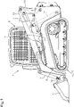
FIG. 1 is a general side view of a working machine. -
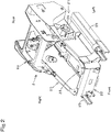
FIG. 2 is a perspective view of a machine body. -
FIG. 3 is a perspective view illustrating how pieces of equipment (devices) are arranged. -
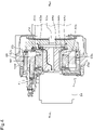
FIG. 4 is a cross-sectional view of an interior of a rotating electrical machine. -
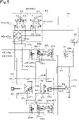
FIG. 5 shows a hydraulic system of a travel system. -
FIG. 6 shows a hydraulic system of a work system. -
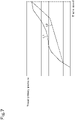
FIG. 7 shows a relationship between engine speed, travel primary pressure, and setting lines. -
FIG. 8 is a control block diagram of the working machine. -
FIG. 9 shows an example of a control map. -
FIG. 10 is a flowchart regarding a starting action. - The following description discusses embodiments of a working machine according to the present invention with reference to drawings.
-
FIG. 1 is a side view of aworking machine 1 according to the present invention.FIG. 1 illustrates a compact track loader as an example of a working machine. Note, however, that the working machine according to the present invention is not limited to a compact track loader and may be, for example, another type of loader working machine such as a skid-steer loader. The working machine according to the present invention may be a working machine other than loader working machines. Note that the description in the present invention is based on the assumption that the front end (left inFIG. 1 ) of the working machine as viewed from an operator seated on an operator's seat of the working machine is "front" or forward", that the rear end (right inFIG. 1 ) as viewed from the operator is "rear" or "rearward", that the left side (near side inFIG. 1 ) as viewed from the operator is "left" or "leftward", and that the right side (far side inFIG. 1 ) as viewed from the operator is "right" or "rightward". The description may be based on the assumption that a direction orthogonal to a front-rear direction of the machine body is "machine body width direction (width direction)." - The working
machine 1 includes amachine body 2, aworking device 3, and a pair oftraveling devices - A
cabin 5 is mounted above a front portion of themachine body 2. A rear portion of thecabin 5 is supported on a bracket of themachine body 2 swingably about a support shaft. - A front portion of the
cabin 5 is configured to be placed on the front portion of themachine body 2. Thecabin 5 is provided with an operator'sseat 7 therein. - The pair of
traveling devices traveling device 4L is provided on one of the opposite sides (left side) of themachine body 2, and thetraveling device 4R is provided on the other of the opposite sides (right side) of themachine body 2. - The
working device 3 includesbooms 10,boom cylinders 14,working tool cylinders 15, and aworking tool 11. Eachboom 10 is supported by alift link 12 and a control link 13. Theboom cylinders 14, which are each composed of a double-acting type hydraulic cylinder, are provided between proximal portions of thebooms 10 and a lower rear portion of themachine body 2. Concurrent extension or retraction of theboom cylinders 14 causes thebooms 10 to swing up or down. Eachboom 10 has, at a distal end thereof, amounting bracket 18 supported pivotably about a lateral axis, and a back of theworking tool 11 is attached tosuch mounting brackets 18 provided on left and right sides. That is, theworking tool 11 is attached to distal ends of thebooms 10. - Furthermore, each of the
working tool cylinders 15, composed of a double-acting type hydraulic cylinder, is provided between acorresponding mounting bracket 18 and an intermediate portion of a distal portion of acorresponding boom 10. Extension or retraction of theworking tool cylinders 15 causes theworking tool 11 to swing (scoop action, dump action). - The
working tool 11 is configured to be attached to and detached from themounting brackets 18. Theworking tool 11 is, for example, an attachment (auxiliary attachment) such as a bucket, a hydraulic crusher, a hydraulic breaker, an angle broom, an earth auger, a pallet fork, a sweeper, a mower, or a snow blower. - The following description discusses the machine body.
- As illustrated in
FIG. 2 , themachine body 2 includes aright frame portion 20, aleft frame portion 21, afront frame portion 22, abottom frame portion 23, and atop frame portion 24. - The
right frame portion 20 forms a right portion of themachine body 2. Theleft frame portion 21 forms a left portion of themachine body 2. Thefront frame portion 22 forms a front portion of themachine body 2 and connects front portions of theright frame portion 20 and theleft frame portion 21 together. Thebottom frame portion 23 forms a bottom portion of themachine body 2 and connects lower portions of theright frame portion 20 and theleft frame portion 21 together. Thetop frame portion 24 forms an upper rear portion of themachine body 2 and connects upper rear portions of theright frame portion 20 and theleft frame portion 21 together. - Rear portions of the
right frame portion 20 and theleft frame portion 21 swingably support thebooms 10 or the like. Theright frame portion 20 and theleft frame portion 21 are each provided with atrack frame 25 and amotor mounting portion 26. - As illustrated in
FIG. 3 , themachine body 2 is provided with anengine 60, acooling fan 61, a radiator, a motor/generator 63, and ahydraulic drive device 64. Theengine 60 is an internal combustion engine such as a diesel engine or a gasoline engine. The coolingfan 61 is a fan for cooling which is driven by power from theengine 60. The radiator cools cooling water for theengine 60. The motor/generator 63 is a device to perform an assisting action in which the motor/generator 63 functions as a motor to assist theengine 60 in driving and an electricity generating action in which the motor/generator 63 functions as a generator to generate electricity using the power from theengine 60. The motor/generator 63 is a motor/generator and employs a permanent magnet three-phase AC synchronous motor as a drive means. - The
hydraulic drive device 64 is a device driven by power from theengine 60 and/or the motor/generator 63, and outputs power mainly for work. Thehydraulic drive device 64 is provided forward of the motor/generator 63. Thehydraulic drive device 64 includes a plurality of hydraulic pumps. The plurality of hydraulic pumps include, for example, as illustrated inFIGS. 5 and6 , atravel pump 52L, atravel pump 52R, a sub-pump P1, and a main pump P2. - The
machine body 2 is provided with abattery 66 and anelectricity control device 67. Thebattery 66 stores electricity generated by the motor/generator 63 and supplies the stored electricity to the motor/generator 63 and the like. As illustrated inFIG. 2 , theelectricity control device 67 includes aninverter 67A and aninverter control unit 67B. The amount of electricity stored in the battery 66 (remaining battery power) can be detected by abattery level sensor 97 of thebattery 66. - With the working
machine 1, thehydraulic drive device 64 can be driven by power from theengine 60, thehydraulic drive device 64 can be driven using both theengine 60 and the motor/generator 63, and the motor/generator 63 can be caused to function to generate electricity using power from theengine 60. That is, transmission of power in the working machine is of parallel hybrid type. The following description discusses a structure which transmits power from theengine 60 and the motor/generator 63. - As illustrated in
FIGS. 3 and4 , ahousing 65 which houses a substantially disc-like flywheel and the motor/generator 63 is provided in front of theengine 60. The motor/generator 63 includes: aconnection part 63a connected to the flywheel; arotor 63b fixed to theconnection part 63a; astator 63c provided on therotor 63b; and awater jacket 63d provided outside thestator 63c. - The
connection part 63a is in the form of a tube and has a rear end attached to the flywheel. Theconnection part 63a has anintermediate shaft 68a provided in the space defined thereby. Theintermediate shaft 68a has acoupling 68b provided at a rear end thereof, and an outer edge of thecoupling 68b is connected to the flywheel. Furthermore, theintermediate shaft 68a has a drive shaft of thehydraulic drive device 64 connected to a front end thereof. - Accordingly, when the
engine 60 is driven, rotating power from a crankshaft (output shaft) 60a of theengine 60 is transmitted to the flywheel and causes the flywheel to rotate. As indicated by arrow F1 inFIG. 4 , the rotating power from the flywheel is transmitted from thecoupling 68b to theintermediate shaft 68a and then transmitted from theintermediate shaft 68a to the drive shaft of thehydraulic drive device 64, making it possible to drive thehydraulic drive device 64. - Furthermore, as indicated by arrow F2 in
FIG. 4 , the rotating power from the flywheel is transmitted via theconnection part 63a to therotor 63b. Therefore, transmission of the rotating power from theengine 60 to therotor 63b (connection part 63a) allows the motor/generator 63 to function as a generator. On the other hand, supplying electricity stored in thebattery 66 to thestator 63c allows therotor 63b to rotate. As indicated by arrow F3, the rotating power from therotor 63b can be transmitted to the flywheel via theconnection part 63a. This makes it possible to cause the motor/generator 63 to function as an electric motor to assist theengine 60. -
FIGS. 5 and6 each show a hydraulic circuit (hydraulic system) of the working machine.FIG. 5 is a hydraulic system of a travel system, andFIG. 6 is a hydraulic system of a work system. - As shown in
FIG. 5 , the hydraulic system of the travel system is a system to cause the travelingdevices hydraulic drive device 64 is driven. The hydraulic system of the travel system includes: the sub-pump P1 which is a hydraulic pump to discharge hydraulic fluid; a firsttravel motor mechanism 31L; a secondtravel motor mechanism 31R; and atravel drive mechanism 34. - The sub-pump P1 is composed of a fixed displacement gear pump. The sub-pump P1 is configured to discharge hydraulic fluid from a tank (hydraulic fluid tank). There is a
discharge fluid passage 40, which allows passage of hydraulic fluid, on the discharge side of the sub-pump P1. Thedischarge fluid passage 40 has a firstcharge fluid passage 41 connected to the discharge side thereof. The firstcharge fluid passage 41 extends to reach thetravel drive mechanism 34. The part of the hydraulic fluid discharged from the sub-pump P1 that is used for control may be referred to as pilot fluid, and the pressure of the pilot fluid may be referred to as pilot pressure. - The
travel drive mechanism 34 is a mechanism to drive the firsttravel motor mechanism 31L and the secondtravel motor mechanism 31R, and includes a driver circuit (left driver circuit) 34L for driving the firsttravel motor mechanism 31L and a driver circuit (right driver circuit) 34R for driving the secondtravel motor mechanism 31R. - The
driver circuits respective travel pumps fluid passages 57h and 57i, and a secondcharge fluid passage 42. The speedchange fluid passages 57h and 57i are fluid passages connecting the travel pumps 52L and 52R withtravel motors charge fluid passage 42 is a fluid passage connected to the speedchange fluid passages 57h and 57i and supplies hydraulic fluid from the sub-pump P1 to the speedchange fluid passages 57h and 57i. Each of the travel pumps 52L and 52R is a swash-plate variable displacement axial pump driven by power from theengine 60. The travel pumps 52L and 52R each includepressure receivers pressure receivers devices - The first
travel motor mechanism 31L is a mechanism which transmits power to a drive shaft of the travelingdevice 4L provided on the left side of themachine body 2. The secondtravel motor mechanism 31R is a mechanism which transmits power to a drive shaft of the travelingdevice 4R provided on the right side of themachine body 2. The firsttravel motor mechanism 31L includestravel motors - Each of the
travel motors travel motor 36L is attached to themotor mounting portion 26 of theleft frame portion 21 and transmits power for travel to the travelingdevice 4L. Thetravel motor 36R is attached to themotor mounting portion 26 of theright frame portion 20 and transmits power for travel to the travelingdevice 4R. Each of thetravel motors travel motors machine 1, i.e., the driving force for the travelingdevices - The speed change mechanism includes a swash
plate switching cylinder 38a and atravel switching valve 38b. The swashplate switching cylinder 38a is a cylinder which extends and retracts to change the swash plate angle of a corresponding one of thetravel motors travel switching valve 38b is a valve which allows the swashplate switching cylinder 38a to extend/retract in either of two directions, and is a two-way switching valve which achieves switching between afirst position 39a and asecond position 39b. Thetravel switching valve 38b is caused to switch between the first andsecond positions change switching valve 44. The speedchange switching valve 44 is connected to thedischarge fluid passage 40 and is also connected to thetravel switching valve 38b of the firsttravel motor mechanism 31L and thetravel switching valve 38b of the secondtravel motor mechanism 31R. The speedchange switching valve 44 is a two-way switching valve which achieves switching between afirst position 44a and asecond position 44b. When the speedchange switching valve 44 is in thefirst position 44a, the pressure of hydraulic fluid acting on thetravel switching valves 38b of the speed change mechanisms is set to a pressure corresponding to a predetermined speed (for example, first speed stage). When the speedchange switching valve 44 is in thefirst position 44a, the pressure of the hydraulic fluid acting on thetravel switching valves 38b is set to a pressure corresponding to a speed (second speed stage) higher than the predetermined speed (first speed stage). Thus, when the speedchange switching valve 44 is in thefirst position 44a, eachtravel switching valve 38b is brought into thefirst position 39a, causing each swashplate switching cylinder 38a to retract and changing the speed stage of thetravel motors change switching valve 44 is in thesecond position 44b, eachtravel switching valve 38b is brought into thesecond position 39b, causing each swashplate switching cylinder 38a to extend and changing the speed stage of thetravel motors travel motors work control device 70. For example, thework control device 70 is provided with anoperation member 58 such as a switch (speed change switch) (seeFIG. 8 ). Upon shifting of theoperation member 58 into first speed stage, thework control device 70 outputs a control signal to deenergize a solenoid of the speedchange switching valve 44 to bring the speedchange switching valve 44 into thefirst position 44a. Upon shifting of theoperation member 58 into second speed stage, thework control device 70 outputs a control signal to energize the solenoid of the speedchange switching valve 44 to bring the speedchange switching valve 44 into thesecond position 44b. - As illustrated in
FIG. 5 , the workingmachine 1 includes anoperation device 53. Theoperation device 53 is a device for operation of the travelingdevices travel motor mechanism 31L, the secondtravel motor mechanism 31R, and thetravel drive mechanism 34. Theoperation device 53 includes atravel operation member 54 and a plurality of operation valves 55 (55a, 55b, 55c, and 55d). The plurality of operation valves 55 (55a, 55b, 55c, and 55d) are travel operation valves. - The
travel operation member 54 is an operation member which is supported on theoperation valves 55 and which swings sideways (along the machine body width direction) and along the front-rear direction. The plurality ofoperation valves 55 are operated by the sametravel operation member 54, i.e., by a singletravel operation member 54. The plurality ofoperation valves 55 function based on the swinging movement of thetravel operation member 54. Hydraulic fluid (pilot fluid) can be supplied from the sub-pump P1 through thedischarge fluid passage 40 to the plurality ofoperation valves 55. The plurality ofoperation valves 55 are theoperation valve 55a, theoperation valve 55b, theoperation valve 55c, and theoperation valve 55d. - The plurality of
operation valves 55 and the travel drive mechanism 34 (travel pumps 52L and 52R) of the travel system are connected by atravel fluid passage 45. Thetravel fluid passage 45 includes a firsttravel fluid passage 45a, a secondtravel fluid passage 45b, a thirdtravel fluid passage 45c, a fourthtravel fluid passage 45d, and a fifthtravel fluid passage 45e. The firsttravel fluid passage 45a is a fluid passage connected to thepressure receiver 52a of thetravel pump 52L. The secondtravel fluid passage 45b is a fluid passage connected to thepressure receiver 52b of thetravel pump 52L. The thirdtravel fluid passage 45c is a fluid passage connected to thepressure receiver 52a of thetravel pump 52R. The fourthtravel fluid passage 45d is a fluid passage connected to thepressure receiver 52b of thetravel pump 52R. The fifthtravel fluid passage 45e is a fluid passage which connects theoperation valves 55, the firsttravel fluid passage 45a, the secondtravel fluid passage 45b, the thirdtravel fluid passage 45c, and the fourthtravel fluid passage 45d. The fifthtravel fluid passage 45e connects a plurality ofshuttle valves 46 and the plurality of operation valves 55 (55a, 55b, 55c, and 55d). - Upon forward (in the direction indicated by arrow A1 in
FIG. 5 ) swinging movement of thetravel operation member 54, theoperation valve 55a is operated, pilot pressure is determined by theoperation valve 55a, the determined pilot pressure acts on thepressure receivers 52a of the travel pumps 52L and 52R, and the swash plate of each of the travel pumps 52L and 52R is tilted from a neutral position in a normal rotation direction, thereby causing the travel pumps 52L and 52R to discharge hydraulic fluid. It follows thatoutput shafts travel motors travel operation member 54, and that the workingmachine 1 travels forward in a straight line. - Upon rearward (in the direction indicated by arrow A2 in
FIG. 5 ) swinging movement of thetravel operation member 54, theoperation valve 55b is operated, pilot pressure is determined by theoperation valve 55b, the determined pilot pressure acts on thepressure receivers 52b of the travel pumps 52L and 52R, and the swash plate of each of the travel pumps 52L and 52R is tilted from the neutral position in a reverse rotation direction, thereby causing the travel pumps 52L and 52R to discharge hydraulic fluid. It follows that theoutput shafts travel motors travel operation member 54, and that the workingmachine 1 travels rearward in a straight line. - Upon rightward (in the direction indicated by arrow A3 in
FIG. 5 ) swinging movement of thetravel operation member 54, theoperation valve 55c is operated, pilot pressure is determined by theoperation valve 55c, the determined pilot pressure acts on thepressure receiver 52a of the travel pump 52L and thepressure receiver 52b of the travel pump 52R, and the swash plate of thetravel pump 52L is tilted in the normal rotation direction and the swash plate of thetravel pump 52R is tilted in the reverse rotation direction. It follows that theoutput shaft 35L of thetravel motor 36L on the left side rotates in the normal direction and theoutput shaft 35R of thetravel motor 36R on the right side rotates in the reverse direction, so that the workingmachine 1 turns right (makes a spin turn). Upon leftward (in the direction indicated by arrow A4 inFIG. 5 ) swinging movement of thetravel operation member 54, theoperation valve 55d is operated, pilot pressure is determined by theoperation valve 55d, the determined pilot pressure acts on thepressure receiver 52b of the travel pump 52L and thepressure receiver 52a of the travel pump 52R, and the swash plate of thetravel pump 52L is tilted in the reverse rotation direction and the swash plate of thetravel pump 52R is tilted in the normal rotation direction. It follows that theoutput shaft 35L of thetravel motor 36L on the left side rotates in the reverse direction and theoutput shaft 35R of thetravel motors 36R on the right side rotates in the normal direction, so that the workingmachine 1 turns left (makes a spin turn). - Upon diagonal swinging movement of the
travel operation member 54, the difference between the pilot pressure acting on thepressure receivers 52a and the pilot pressure acting on thepressure receivers 52b determines the direction and speed of rotation of theoutput shafts travel motor 36L on the left side and thetravel motor 36R on the right side, and the workingmachine 1 turns right (makes a right pivot turn) or turns left (makes a left pivot turn) while traveling forward or rearward. - The working
machine 1 may include ananti-stall control valve 48. Theanti-stall control valve 48 is disposed in the fluid passage (discharge fluid passage 40) between the plurality of operation valves 55 (55a, 55b, 55c, and 55d) and the sub-pump P1. Theanti-stall control valve 48 is a proportional solenoid valve, and the degree of opening of theanti-stall control valve 48 is variable. Theanti-stall control valve 48 is configured to determine, according to a decrease (drop) ΔE1 in rotation speed of the engine 60 (engine speed), pilot pressure (primary pilot pressure) which acts on the plurality of operation valves 55 (55a, 55b, 55c, and 55d). The rotation speed of the engine can be detected by anengine speed sensor 91. The engine speed detected by thesensor 91 is inputted into thework control device 70. -
FIG. 7 shows a relationship between engine speed, travel primary pressure (primary pilot pressure), and setting lines L51 and L52. The setting line L51 represents a relationship between engine speed and travel primary pressure where the decrease ΔE1 is less than a predetermined value (less than anti-stall reference value). The setting line L52 represents a relationship between engine speed and travel primary pressure where the decrease ΔE1 is equal to or greater than the anti-stall reference value. - When the decrease ΔE1 is less than the anti-stall reference value, the
work control device 70 adjusts the degree of opening of theanti-stall control valve 48 so that the relationship between the engine speed and the travel primary pressure matches a reference pilot pressure represented by the setting line L51. When the decrease ΔE1 is equal to or greater than the anti-stall reference value, thework control device 70 adjusts the degree of opening of theanti-stall control valve 48 so that the relationship between the engine speed and the travel primary pressure matches the setting line L52 which is below the reference pilot pressure. The travel primary pressure at a certain engine speed is lower on the setting line L52 than on the setting line L51. That is, when focus is put on a single engine speed, the travel primary pressure on the setting line L52 is set to be lower than the travel primary pressure on the setting line L51. Accordingly, with the control based on the setting line L52, the pressure of hydraulic fluid entering theoperation valves 55 is kept low (pilot pressure is kept low). It follows that the swash plate angle of the travel pumps 52L and 52R is adjusted, the load on the engine is reduced, and the engine is prevented from stalling. Note that, althoughFIG. 7 shows a single setting line L52, a plurality of setting lines L52 may be present. For example, the setting lines L52 may be set for respective engine speeds. Data indicative of the setting line L51 and the setting line L52, control parameters such as functions, or the like are preferably stored in thework control device 70. - As illustrated in
FIG. 6 , the hydraulic system of the work system is a system to cause the workingdevice 3 and/or the like to function. The hydraulic system of the work system is a system to cause the workingdevice 3 to function using hydraulic pressure that occurs when thehydraulic drive device 64 is driven. The hydraulic system of the work system includes a plurality ofcontrol valves 51 and a main pump P2 which is a hydraulic pump that discharges hydraulic fluid. The main pump P2 is located at a different position from the sub-pump P1, and is composed of a small displacement gear pump. The main pump P2 is configured to discharge hydraulic fluid from a hydraulic fluid tank. In particular, the main pump P2 mainly discharges hydraulic fluid to activate a hydraulic actuator. - There is a
fluid passage 51f on the discharge side of the main pump P2. Thefluid passage 51f has the plurality ofcontrol valves 51 connected thereto. The plurality ofcontrol valves 51 include aboom control valve 51a, abucket control valve 51b, and anauxiliary control valve 51c. Theboom control valve 51a is a valve to control theboom cylinders 14, thebucket control valve 51b is a valve to control the workingtool cylinders 15, and theauxiliary control valve 51c is a valve to control a hydraulic actuator of the auxiliary attachment. - The
booms 10 and the workingtool 11 can be operated using awork operation member 37 of anoperation device 43. Thework operation member 37 is an operation member which is supported on a plurality ofoperation valves 59 and which swings sideways (along the machine body width direction) and along the front-rear direction. Theoperation valves 59 provided at the bottom of thework operation member 37 can be operated by tilting operation of thework operation member 37. - The plurality of
operation valves 59 and the plurality ofcontrol valves 51 are connected to each other by a plurality of work fluid passages 47 (47a, 47b, 47c, and 47d). Specifically, theoperation valve 59a is connected to theboom control valve 51a via thework fluid passage 47a. Theoperation valve 59b is connected to theboom control valve 51a via thework fluid passage 47b. Theoperation valve 59c is connected to thebucket control valve 51b via thework fluid passage 47c. Theoperation valve 59d is connected to thebucket control valve 51b via thework fluid passage 47d. The plurality of theoperation valves 59a to 59d are each configured to determine, according to the operation of thework operation member 37, the pressure of hydraulic fluid to be outputted. - Upon forward tilting movement of the
work operation member 37, theoperation valve 59a is operated to output pilot pressure. The pilot pressure acts on a pressure receiver of theboom control valve 51a and hydraulic fluid having entered theboom control valve 51a is supplied to the rod side of each of theboom cylinders 14, thereby lowering thebooms 10. - Upon rearward tilting movement of the
work operation member 37, theoperation valve 59b is operated to output pilot pressure. The pilot pressure acts on another pressure receiver of theboom control valve 51a and hydraulic fluid having entered theboom control valve 51a is supplied to the bottom side of each of theboom cylinders 14, thereby raising thebooms 10. - That is, the
boom control valve 51a is configured to control the flow rate of hydraulic fluid flowing to theboom cylinders 14 according to the pressure of hydraulic fluid determined by the operation of the work operation member 37 (pilot pressure determined by theoperation valve 59a, pilot pressure determined by theoperation valve 59b). - Upon rightward tilting movement of the
work operation member 37, theoperation valve 59c is operated and pilot pressure acts on a pressure receiver of thebucket control valve 51b. It follows that thebucket control valve 51b functions to cause the workingtool cylinders 15 to extend, and the workingtool 11 performs a dump action at a speed proportional to the amount of the tilting movement of thework operation member 37. - Upon leftward tilting movement of the
work operation member 37, theoperation valve 59d is operated and pilot fluid acts on another pressure receiver of thebucket control valve 51b. It follows that thebucket control valve 51b functions to cause the workingtool cylinders 15 to retract, and the workingtool 11 performs a scoop action at a speed proportional to the amount of the tilting movement of thework operation member 37. - That is, the
bucket control valve 51b is configured to control the flow rate of hydraulic fluid flowing to the workingtool cylinders 15 according to the pressure of hydraulic fluid determined by the operation of the work operation member 37 (pilot pressure determined by theoperation valve 59c, pilot pressure determined by theoperation valve 59d). That is, theoperation valves work operation member 37, and supply the hydraulic fluid having been subjected to pressure change to control valves such as theboom control valve 51a, thebucket control valve 51b, and/or theauxiliary control valve 51c. - The auxiliary attachment can be operated using a
switch 56 provided in the vicinity of the operator's seat 7 (seeFIG. 8 ). Theswitch 56 is composed of, for example, a swingable seesaw-type switch, a slidable slide-type switch, or a push-type switch that can be pressed. The operation of theswitch 56 is inputted into thecontrol device 70. Afirst solenoid valve 56a and asecond solenoid valve 56b, each composed of a solenoid valve or the like, open according to the operation amount of theswitch 56. It follows that pilot fluid is supplied to theauxiliary control valve 51c connected to thefirst solenoid valve 56a and thesecond solenoid valve 56b, and an auxiliary actuator of the auxiliary attachment is activated by hydraulic fluid supplied from theauxiliary control valve 51c. - Note that the operation amount of an operation member (
work operation member 37, travel operation member 54) can be detected by anoperation detecting device 77. Theoperation detecting device 77 is connected to the work control device 70 (described later). Theoperation detecting device 77 includes a firstoperation detecting device 77A and a secondoperation detecting device 77B. The firstoperation detecting device 77A detects the operation amount of the work operation member 37 (work operation amount). The secondoperation detecting device 77B detects the operation amount of the travel operation member 54 (travel operation amount). The firstoperation detecting device 77A and the secondoperation detecting device 77B are each, for example, a position sensor to detect the position of the operation member. -
FIG. 8 is a control block diagram of the workingmachine 1. As illustrated inFIG. 8 , theelectricity control device 67 and thework control device 70 are connected to each other. Theelectricity control device 67 includes theinverter 67A and theinverter control unit 67B. Theinverter 67A includes, for example, a plurality of switching elements, and, for example, convers direct current into alternating current by, for example, turning ON and OFF the switching elements. Theinverter 67A is connected to the motor/generator 63 and thebattery 66. Theinverter control unit 67B is composed of a CPU, an electrical/electronic circuit, and/or the like. By outputting a predetermined signal to theinverter control unit 67B, the motor/generator 63 is caused to function as a motor or function as a generator. The amount of electricity stored in the battery 66 (remaining battery power) can be detected by thebattery level sensor 97 of thebattery 66. - The
work control device 70 is a device to perform various types of control relating to the working machine, and is composed of a CPU, an electrical/electronic circuit, and/or the like. Thework control device 70 performs control relating to hydraulic pressure (hydraulic fluid) (such control is hydraulic pressure control). In the hydraulic pressure control, thework control device 70 energizes and deenergizes the solenoids of the speedchange switching valve 44, thefirst solenoid valve 56a, and thesecond solenoid valve 56b, as described earlier. Thework control device 70 also acts as a controller to control theelectricity control device 67. Thework control device 70 outputs an assist command to theinverter control unit 67B, and theinverter control unit 67B causes the motor/generator 63 to function as a motor. Thework control device 70 outputs an electricity generation command to theinverter control unit 67B, and theinverter control unit 67B causes the motor/generator 63 to function as a generator. That is, thework control device 70 controls the motor/generator 63 to perform an assisting action in which the motor/generator 63 assists theengine 60 in driving and an electricity generating action in which the motor/generator 63 functions as a generator to generate electricity using power from theengine 60. Note that thework control device 70 sends, to theelectricity control device 67, settings and commands regarding motoring torque in the case of the assisting action of the motor/generator 63 and regenerative torque in the case of the electricity generating action of the motor/generator 63. - When the motor/
generator 63 performs the assisting action, power from theengine 60 and the motor/generator 63 is transmitted to thehydraulic drive device 64. When the motor/generator 63 performs the electricity generating action, power from theengine 60 is transmitted to thehydraulic drive device 64, and electricity generated by the motor/generator 63 is stored in thebattery 66. The motor/generator 63 is driven by the electricity stored in thebattery 66. - Note that, although the
work control device 70 and theelectricity control device 67 are separate devices in the above-described embodiment, thework control device 70 and theelectricity control device 67 may be composed of a single device. The above-described embodiment does not imply limitation. - The
work control device 70 includes astorage unit 70a, anaction control unit 70d, a startingaction determining unit 70e, afirst setting unit 70f, and asecond setting unit 70g. Thestorage unit 70a is composed of a nonvolatile memory or the like. Theaction control unit 70d, the startingaction determining unit 70e, thefirst setting unit 70f, and thesecond setting unit 70g are composed of electrical/electronic circuit(s) of thework control device 70, program(s) stored in the CPU and/or the like of thework control device 70, and/or the like. Thestorage unit 70a, theaction control unit 70d, the startingaction determining unit 70e, thefirst setting unit 70f, and thesecond setting unit 70g may be provided in theelectricity control device 67. - The
storage unit 70a stores therein control information for use when the motor/generator 63 performs the assisting action or charging action e.g., a control map as shown inFIG. 9 . The control map indicates: a relationship between the rotation speed of the engine 60 (engine speed) and switching between the assisting action and the charging action (switching between actions); a relationship between engine speed and motoring torque in the case of the assisting action; and a relationship between engine speed and regenerative torque in the case of the charging action. Note that, although the control information is a control map in the above-described embodiment, the relationship between engine speed and switching between actions, the relationship between engine speed and motoring torque in the case of the assisting action, and the relationship between engine speed and regenerative torque in the case of the charging action may be represented by a control table, parameters, functions, and/or the like, and the above-described embodiment does not imply limitation. Note that the rotation speed of the engine can be detected by theengine speed sensor 91. The engine speed detected by thesensor 91 is inputted into thework control device 70. - As shown in
FIG. 9 , a standard line L1 is a line defined by second control information indicating the relationship between motoring torque for the assisting action and engine speed and the relationship between regenerative torque for the charging action and engine speed. The standard line L1 includes: a sloping line L1a in which the torque changes with engine speed; and a constant line L1b in which the torque is constant regardless of engine speed. - The
work control device 70 has, as control information, first control information which defines a correction line L5 (line indicating the relationship between motoring torque and engine speed and the relationship between regenerative torque and engine speed) which differs from the standard line L1. The correction line L5 is not limited, and may be a line prepared by thework control device 70 at the time of control or may be pre-stored in thestorage unit 70a, as described later. - The starting
action determining unit 70e determines, upon operation of an operation member such as thetravel operation member 54, whether the operation corresponds to a starting action for themachine body 2. If the startingaction determining unit 70e determines that the operation corresponds to the starting action, thefirst setting unit 70f sets the motoring torque or regenerative torque for the assisting action or the electricity generating action to the torque represented by the correction line L5, when torque control is changed from the control at the time of the starting action (at a point in time P11) back to the control based on the standard line L1. - If the starting
action determining unit 70e determines that the operation does not correspond to the starting action, thesecond setting unit 70g sets the torque (the motoring torque or regenerative torque) for the assisting action or electricity generating action to the motoring torque corresponding to the engine speed using the standard line L1. - The
action control unit 70d outputs, to theelectricity control device 67, the torque set by thefirst setting unit 70f or thesecond setting unit 70g, and thereby the assisting action or the electricity generating action is performed. - The following description specifically discusses actions performed in the case of the starting action and actions performed in the case of an action other than the starting action, with reference to
FIGS. 9 and10 . - As shown in
FIG. 10 , thework control device 70 determines whether or not themachine body 2 is in its stopped state, i.e., the travelingdevices travel operation member 54 is operated while the travelingdevices action determining unit 70e determines whether or not the amount of change ΔW10 of thetravel operation member 54 per unit time is equal to or greater than a predetermined amount (Yes in S61). If the amount of change ΔW10 is equal or greater than a predetermined amount (Yes in S61), the startingaction determining unit 70e determines that the operation corresponds to a starting action (S62). Thefirst setting unit 70f performs a predetermined action corresponding to starting state. Then, if the engine speed increases, thefirst setting unit 70f sets motoring torque or regenerative torque on the basis of the correction line L5 (S63). Theaction control unit 70d causes the assisting action or electricity generating action to be performed according to the motoring torque or regenerative torque set by thefirst setting unit 70f (S64). If the motoring torque or regenerative torque set by thefirst setting unit 70f is equal to that of the standard line L1, the setting by thefirst setting unit 70f ends (S65). - For example, as shown in
FIG. 9 , if the operation of thetravel operation member 54 at the point in time P10 is abrupt (if the amount of change ΔW10 is equal to or greater than a predetermined amount), i.e., if the operation of thetravel operation member 54 corresponds to the starting action, engine speed first decreases after the start of the operation of thetravel operation member 54 and then starts increasing, as indicated by changes K1. At the point in time P11, if the startingaction determining unit 70e determines that the operation corresponds to the starting action, thefirst setting unit 70f provides assistance although the standard line L1 indicates charging. Then, motoring torque is set according to the correction line L5. The correction line L5 is a line in which motoring torque gradually decreases from the point in time at which the determination regarding the starting action was completed (point in time P11) whereas regenerative torque gradually increases from the point in time P11. The slope of the correction line L5 is steeper than the slope of the sloping line L1a of the standard line L1. That is, the amount of change (an increase or decrease) in torque per revolution (per engine revolution) in the correction line L5 is greater than the amount of change per revolution in the sloping line L1a. Note that the correction line L5 is a line not perpendicular to (not at a right angle to) the X axis representing engine speed. - The
first setting unit 70f gradually reduces the motoring torque from the point in time P11 according to the correction line L5, and then increases the regenerative torque. Thefirst setting unit 70f completes setting at the time at which the regenerative torque reaches the standard line L1. - On the other hand, if the amount of
change ΔW 10 is less than the predetermined amount (No in S61), the startingaction determining unit 70e determines that the operation does not correspond to the starting action (S66), and thesecond setting unit 70g sets motoring torque or regenerative torque on the basis of the standard line L1 (S67). Theaction control unit 70d performs the assisting action or electricity generating action according to the motoring torque or regenerative torque set by thesecond setting unit 70g (S68). - Note that the starting
action determining unit 70e may determine that the operation corresponds to the starting action if the amount of change ΔW10 of thetravel operation member 54 per unit time is equal to or greater than a predetermined amount and a decrease ΔE1 in engine speed is equal to or greater than a predetermined value. After the startingaction determining unit 70e determines that the operation corresponds to the starting action, thefirst setting unit 70f generates a correction line L6 which continues from the torque at which the operation was determined as corresponding to the starting action, and sets motoring torque on the basis of the correction line L6. The correction line L6 is a line in the form of an arc. Thefirst setting unit 70f sets motoring torque or regenerative torque along the arc of the correction line L6, and thereby performs processing to bring the torque after the determination regarding the starting action back to the standard line L1. Note that the correction lines L5 and L6 may be stored in thework control device 70 as control information. That is, the correction lines L5 and L6 may be fixed lines prepared in advance. Alternatively, the correction lines L5 and L6 may be set according to the decrease ΔE1 in engine speed before the determination regarding the starting action, may be set according to the total decrease ΔE1 in engine speed, and may be set in some other manner. - The following may be employed: the
action control unit 70d causes the charging action to be performed when, in the case where the startingaction determining unit 70e determines that the operation corresponds to the starting action, the point in time at which the determination regarding the starting action was performed is on the assisting action side and the remaining battery power (amount of stored electricity) of thebattery 66 is smaller than a predetermined remaining battery power. - As shown in
FIG. 9 , if the operation of thetravel operation member 54 at the point in time P10 is not abrupt (if the amount of change ΔW10 is less than a predetermine amount), thesecond setting unit 70g sets regenerative torque according to the engine speed at the point in time P10 on the standard line L1, and theaction control unit 70d causes the electricity generating action to be performed. - A working
machine 1 comprises: amachine body 2; anengine 60; a motor/generator 63; abattery 66; an operation member; a startingaction determining unit 70e to determine, upon operation of the operation member, whether the operation corresponds to a starting action for themachine body 2; afirst setting unit 70f to set, if the startingaction determining unit 70e determines that the operation of the operation member corresponds to the starting action, a torque of the motor/generator 63 for the assisting action or the electricity generating action to a first torque; and asecond setting unit 70g to set, if the startingaction determining unit 70e determines that the operation of the operation member does not correspond to the starting action, the torque for the assisting action or the electricity generating action to a second torque differing from the first torque set by thefirst setting unit 70f. This makes it possible to efficiently perform the assisting action or the electricity generating action when a starting action for the workingmachine 1 is performed. That is, even in the case where the engine speed decreases when a starting action for the workingmachine 1 is performed, it is possible to stably perform the assisting action or the electricity generating action. - The starting
action determining unit 70e determines that the operation of the operation member corresponds to the starting action if an amount of change of the operation member is equal to or greater than a predetermined amount, and determines that the operation of the operation member does not correspond to the starting action if the amount of change of the operation member is less than the predetermined amount. This makes it possible to easily detect whether or not the operation of the operation member corresponds to the starting action, on the basis of the operation of the operation member. - The
machine body 2 includes travelingdevices generator 63; and the operation member is atravel operation member 54 for operation of the traveling devices. This makes it possible to properly perform the assisting action when the workingmachine 1 in its stopped state is started to travel. - The
first setting unit 70f sets the torque on the basis of first control information indicating a relationship between a rotation speed of the engine and the first torque; and thesecond setting unit 70g sets the torque on the basis of second control information indicating a relationship between the rotation speed of the engine and the second torque, the other relationship differing from the relationship used by thefirst setting unit 70f. This makes it possible to properly set the torque to that corresponding to the engine speed differently in the case where the operation of the operation member corresponds to the starting action and in the case where the operation of the operation member does not correspond to the starting action. - The starting
action determining unit 70e determines whether or not the operation of the operation member corresponds to the starting action on the basis of a decrease ΔE1 in the rotation speed of the engine in a case where the operation member is operated. This makes it possible to easily determine whether the operation of the operation member corresponds to the starting action on the basis of the load on theengine 60 at the time of the starting action, i.e., on the basis of the decrease ΔE1. - The above-described embodiment employs a configuration in which, when the
work operation member 37 and the travel operation member 57 are operated, theoperation valves operation devices hydraulic drive device 64 and thecontrol valves - While the present invention has been described above, it is to be understood that the embodiments disclosed herein are considered as examples in all aspects and are not considered as limitations. The scope of the present invention is to be determined not by the foregoing description but by the claims, and is intended to include all variations and modifications within the scope of the claims and their equivalents.
-
- 1
- Working machine
- 2
- Machine body
- 3
- Working device
- 4L
- Traveling device
- 4R
- Traveling device
- 5
- Cabin
- 7
- Operator's seat
- 10
- Boom
- 11
- Working tool
- 12
- Lift link
- 13
- Control link
- 14
- Boom cylinder
- 15
- Working tool cylinder
- 18
- Mounting bracket
- 20
- Right frame portion
- 21
- Left frame portion
- 22
- Front frame portion
- 23
- Bottom frame portion
- 24
- Top frame portion
- 25
- Track frame
- 26
- Motor mounting portion
- 31L
- First travel motor mechanism
- 31R
- Second travel motor mechanism
- 34
- Travel drive mechanism
- 34L
- Driver circuit
- 34R
- Driver circuit
- 35L
- Output shaft
- 35R
- Output shaft
- 36L
- Travel motor
- 36R
- Travel motor
- 37
- Work operation member
- 38a
- Swash plate switching cylinder
- 38b
- Travel switching valve
- 39a
- First position
- 39b
- Second position
- 40
- Discharge fluid passage
- 41
- First charge fluid passage
- 42
- Second charge fluid passage
- 43
- Operation device
- 44
- Speed change switching valve
- 44a
- First position
- 44b
- Second position
- 45
- Travel fluid passage
- 45a
- First travel fluid passage
- 45b
- Second travel fluid passage
- 45c
- Third travel fluid passage
- 45d
- Fourth travel fluid passage
- 45e
- Fifth travel fluid passage
- 46
- Shuttle valve
- 47
- Work fluid passage
- 47a
- Work fluid passage
- 47b
- Work fluid passage
- 47c
- Work fluid passage
- 47d
- Work fluid passage
- 48
- Anti-stall control valve
- 51
- Control valve
- 51a
- Boom control valve
- 51b
- Bucket control valve
- 51c
- Auxiliary control valve
- 51f
- Fluid passage
- 52L
- Travel pump
- 52R
- Travel pump
- 52a
- Pressure receiver
- 52b
- Pressure receiver
- 53
- Operation device
- 54
- Travel operation member
- 55
- Operation valve
- 55a
- Operation valve
- 55b
- Operation valve
- 55c
- Operation valve
- 55d
- Operation valve
- 56
- Switch
- 56a
- First solenoid valve
- 56b
- Second solenoid valve
- 57h
- Speed change fluid passage
- 57i
- Speed change fluid passage
- 58
- Operation member
- 59
- Operation valve
- 59a
- Operation valve
- 59b
- Operation valve
- 59c
- Operation valve
- 59d
- Operation valve
- 60
- Engine
- 61
- Cooling fan
- 63
- Motor/generator
- 63a
- Connection part
- 63b
- Rotor
- 63c
- Stator
- 63d
- Water jacket
- 64
- Hydraulic drive device
- 65
- Housing
- 66
- Battery
- 67
- Electricity control device
- 67A
- Inverter
- 67B
- Inverter control unit
- 68a
- Intermediate shaft
- 68b
- Coupling
- 70
- Work control device
- 70a
- Storage unit
- 70d
- Action control unit
- 70e
- Starting action determining unit
- 70f
- First setting unit
- 70g
- Second setting unit
- 77
- Operation detecting device
- 77A
- First operation detecting device
- 77B
- Second operation detecting device
- 91
- Sensor
- 97
- Battery level sensor
Claims (5)
- A working machine comprising:a machine body;an engine provided on the machine body;a motor/generator to perform an assisting action in which the motor/generator functions as a motor to assist the engine in driving and an electricity generating action in which the motor/generator functions as a generator to generate electricity using power from the engine;a battery to store electricity generated by the motor/generator;an operation member for operation of the machine body;a starting action determining unit to determine, upon operation of the operation member, whether the operation corresponds to a starting action for the machine body;a first setting unit to set, if the starting action determining unit determines that the operation of the operation member corresponds to the starting action, a torque of the motor/generator for the assisting action or the electricity generating action to a first torque; anda second setting unit to set, if the starting action determining unit determines that the operation of the operation member does not correspond to the starting action, the torque for the assisting action or the electricity generating action to a second torque differing from the first torque set by the first setting unit.
- The working machine according to claim 1, wherein the starting action determining unit determines that the operation of the operation member corresponds to the starting action if an amount of change of the operation member is equal to or greater than a predetermined amount, and determines that the operation of the operation member does not correspond to the starting action if the amount of change of the operation member is less than the predetermined amount.
- The working machine according to claim 1 or 2, wherein:the machine body includes a traveling device configured to function using power from the engine and the motor/generator; andthe operation member is a travel operation member for operation of the traveling device.
- The working machine according to any one of claims 1 to 3, wherein:the first setting unit sets the torque on the basis of first control information indicating a relationship between a rotation speed of the engine and the first torque; andthe second setting unit sets the torque on the basis of the second control information indicating a relationship between the rotation speed of the engine and the second torque, the other relationship differing from the relationship used by the first setting unit.
- The working machine according to any one of claims 1 to 4, wherein the starting action determining unit determines whether or not the operation of the operation member corresponds to the starting action on the basis of a decrease in the rotation speed of the engine in a case where the operation member is operated.
Applications Claiming Priority (2)
| Application Number | Priority Date | Filing Date | Title |
|---|---|---|---|
| JP2019122520A JP7171517B2 (en) | 2019-06-28 | 2019-06-28 | work machine |
| PCT/JP2020/024416 WO2020262302A1 (en) | 2019-06-28 | 2020-06-22 | Work machine |
Publications (3)
| Publication Number | Publication Date |
|---|---|
| EP3992374A1 true EP3992374A1 (en) | 2022-05-04 |
| EP3992374A4 EP3992374A4 (en) | 2023-07-19 |
| EP3992374B1 EP3992374B1 (en) | 2026-03-25 |
Family
ID=74061697
Family Applications (1)
| Application Number | Title | Priority Date | Filing Date |
|---|---|---|---|
| EP20833704.8A Active EP3992374B1 (en) | 2019-06-28 | 2020-06-22 | Work machine |
Country Status (4)
| Country | Link |
|---|---|
| US (1) | US11993911B2 (en) |
| EP (1) | EP3992374B1 (en) |
| JP (1) | JP7171517B2 (en) |
| WO (1) | WO2020262302A1 (en) |
Family Cites Families (8)
| Publication number | Priority date | Publication date | Assignee | Title |
|---|---|---|---|---|
| JP3536538B2 (en) * | 1996-07-01 | 2004-06-14 | トヨタ自動車株式会社 | Hybrid vehicle control device |
| JPWO2010147121A1 (en) * | 2009-06-19 | 2012-12-06 | 住友重機械工業株式会社 | Hybrid construction machine and control method of hybrid construction machine |
| JP2013203234A (en) * | 2012-03-28 | 2013-10-07 | Kubota Corp | Hybrid working vehicle |
| US9561789B2 (en) * | 2012-03-28 | 2017-02-07 | Kubota Corporation | Hybrid work vehicle |
| EP2899082B1 (en) * | 2012-09-24 | 2021-01-20 | Kubota Corporation | Vehicle |
| JP2014065347A (en) * | 2012-09-24 | 2014-04-17 | Kubota Corp | Hybrid work vehicle |
| JP6539462B2 (en) * | 2015-03-10 | 2019-07-03 | 日立建機株式会社 | Hybrid work machine |
| JP2017226284A (en) * | 2016-06-21 | 2017-12-28 | 株式会社クボタ | Working machine |
-
2019
- 2019-06-28 JP JP2019122520A patent/JP7171517B2/en active Active
-
2020
- 2020-06-22 WO PCT/JP2020/024416 patent/WO2020262302A1/en not_active Ceased
- 2020-06-22 EP EP20833704.8A patent/EP3992374B1/en active Active
-
2021
- 2021-12-06 US US17/542,577 patent/US11993911B2/en active Active
Also Published As
| Publication number | Publication date |
|---|---|
| US11993911B2 (en) | 2024-05-28 |
| EP3992374B1 (en) | 2026-03-25 |
| WO2020262302A1 (en) | 2020-12-30 |
| JP7171517B2 (en) | 2022-11-15 |
| EP3992374A4 (en) | 2023-07-19 |
| US20220090344A1 (en) | 2022-03-24 |
| JP2021008738A (en) | 2021-01-28 |
Similar Documents
| Publication | Publication Date | Title |
|---|---|---|
| JP3941951B2 (en) | Drive control device for hybrid work machine | |
| KR101652661B1 (en) | Construction machine | |
| CN101855434B (en) | Engine controller | |
| JP5055948B2 (en) | Hybrid work machine | |
| CN104011300A (en) | Rotation control device and method | |
| US20250263908A1 (en) | Working machine | |
| US12031289B2 (en) | Working machine | |
| JP7512232B2 (en) | Work Machine | |
| EP3992374B1 (en) | Work machine | |
| JP4063742B2 (en) | Drive control device for hybrid work machine | |
| JP2011157751A (en) | Hydraulic work machine | |
| JP7171518B2 (en) | work machine | |
| JP7301632B2 (en) | work machine | |
| JP7146703B2 (en) | work machine | |
| JP7155071B2 (en) | work machine | |
| JP7214581B2 (en) | work machine | |
| JP7086898B2 (en) | Working machine | |
| JP7646528B2 (en) | Work Machine | |
| JP7080855B2 (en) | Working machine | |
| CN121110766A (en) | Control methods for construction machinery, control programs for construction machinery, control systems for construction machinery, and construction machinery itself. | |
| WO2020039861A1 (en) | Hybrid construction machine |
Legal Events
| Date | Code | Title | Description |
|---|---|---|---|
| STAA | Information on the status of an ep patent application or granted ep patent |
Free format text: STATUS: THE INTERNATIONAL PUBLICATION HAS BEEN MADE |
|
| PUAI | Public reference made under article 153(3) epc to a published international application that has entered the european phase |
Free format text: ORIGINAL CODE: 0009012 |
|
| STAA | Information on the status of an ep patent application or granted ep patent |
Free format text: STATUS: REQUEST FOR EXAMINATION WAS MADE |
|
| 17P | Request for examination filed |
Effective date: 20211126 |
|
| AK | Designated contracting states |
Kind code of ref document: A1 Designated state(s): AL AT BE BG CH CY CZ DE DK EE ES FI FR GB GR HR HU IE IS IT LI LT LU LV MC MK MT NL NO PL PT RO RS SE SI SK SM TR |
|
| DAV | Request for validation of the european patent (deleted) | ||
| DAX | Request for extension of the european patent (deleted) | ||
| A4 | Supplementary search report drawn up and despatched |
Effective date: 20230620 |
|
| RIC1 | Information provided on ipc code assigned before grant |
Ipc: B60K 6/485 20071001ALI20230614BHEP Ipc: F02D 29/02 20060101ALI20230614BHEP Ipc: F02D 29/00 20060101ALI20230614BHEP Ipc: E02F 9/20 20060101AFI20230614BHEP |
|
| GRAP | Despatch of communication of intention to grant a patent |
Free format text: ORIGINAL CODE: EPIDOSNIGR1 |
|
| STAA | Information on the status of an ep patent application or granted ep patent |
Free format text: STATUS: GRANT OF PATENT IS INTENDED |
|
| INTG | Intention to grant announced |
Effective date: 20251209 |
|
| GRAS | Grant fee paid |
Free format text: ORIGINAL CODE: EPIDOSNIGR3 |
|
| GRAA | (expected) grant |
Free format text: ORIGINAL CODE: 0009210 |
|
| STAA | Information on the status of an ep patent application or granted ep patent |
Free format text: STATUS: THE PATENT HAS BEEN GRANTED |
|
| AK | Designated contracting states |
Kind code of ref document: B1 Designated state(s): AL AT BE BG CH CY CZ DE DK EE ES FI FR GB GR HR HU IE IS IT LI LT LU LV MC MK MT NL NO PL PT RO RS SE SI SK SM TR |
|
| REG | Reference to a national code |
Ref country code: CH Ref legal event code: F10 Free format text: ST27 STATUS EVENT CODE: U-0-0-F10-F00 (AS PROVIDED BY THE NATIONAL OFFICE) Effective date: 20260325 Ref country code: GB Ref legal event code: FG4D |
|
| REG | Reference to a national code |
Ref country code: DE Ref legal event code: R096 Ref document number: 602020069275 Country of ref document: DE |
|
| REG | Reference to a national code |
Ref country code: IE Ref legal event code: FG4D |