EP3992354A1 - Clothes dryer condenser assembly and clothes dryer - Google Patents
Clothes dryer condenser assembly and clothes dryer Download PDFInfo
- Publication number
- EP3992354A1 EP3992354A1 EP20832703.1A EP20832703A EP3992354A1 EP 3992354 A1 EP3992354 A1 EP 3992354A1 EP 20832703 A EP20832703 A EP 20832703A EP 3992354 A1 EP3992354 A1 EP 3992354A1
- Authority
- EP
- European Patent Office
- Prior art keywords
- condenser
- fireproof
- wall
- drying device
- clothes drying
- Prior art date
- Legal status (The legal status is an assumption and is not a legal conclusion. Google has not performed a legal analysis and makes no representation as to the accuracy of the status listed.)
- Withdrawn
Links
- 238000001035 drying Methods 0.000 claims abstract description 58
- XLYOFNOQVPJJNP-UHFFFAOYSA-N water Substances O XLYOFNOQVPJJNP-UHFFFAOYSA-N 0.000 claims description 14
- 230000007704 transition Effects 0.000 claims description 4
- 238000005452 bending Methods 0.000 claims description 3
- 239000011248 coating agent Substances 0.000 claims description 3
- 238000000576 coating method Methods 0.000 claims description 3
- 239000011810 insulating material Substances 0.000 claims description 3
- 238000009423 ventilation Methods 0.000 claims description 3
- 230000000694 effects Effects 0.000 abstract description 6
- 238000009413 insulation Methods 0.000 abstract description 5
- 238000004321 preservation Methods 0.000 abstract description 5
- 238000010586 diagram Methods 0.000 description 3
- 239000003351 stiffener Substances 0.000 description 3
- 238000012986 modification Methods 0.000 description 2
- 230000004048 modification Effects 0.000 description 2
- 230000032683 aging Effects 0.000 description 1
- 230000009286 beneficial effect Effects 0.000 description 1
- 238000009833 condensation Methods 0.000 description 1
- 230000005494 condensation Effects 0.000 description 1
- 239000000463 material Substances 0.000 description 1
- 239000002184 metal Substances 0.000 description 1
- 238000000034 method Methods 0.000 description 1
- 230000002093 peripheral effect Effects 0.000 description 1
- 238000000926 separation method Methods 0.000 description 1
- 239000000126 substance Substances 0.000 description 1
- 238000005406 washing Methods 0.000 description 1
Images

Classifications
-
- D—TEXTILES; PAPER
- D06—TREATMENT OF TEXTILES OR THE LIKE; LAUNDERING; FLEXIBLE MATERIALS NOT OTHERWISE PROVIDED FOR
- D06F—LAUNDERING, DRYING, IRONING, PRESSING OR FOLDING TEXTILE ARTICLES
- D06F58/00—Domestic laundry dryers
- D06F58/20—General details of domestic laundry dryers
- D06F58/24—Condensing arrangements
-
- A—HUMAN NECESSITIES
- A62—LIFE-SAVING; FIRE-FIGHTING
- A62C—FIRE-FIGHTING
- A62C3/00—Fire prevention, containment or extinguishing specially adapted for particular objects or places
- A62C3/16—Fire prevention, containment or extinguishing specially adapted for particular objects or places in electrical installations, e.g. cableways
Definitions
- the disclosure relates to the technical field of clothes drying device, and particularly herein, relates to a clothes drying device condenser assembly and a clothes drying device.
- clothes drying device With the improvement of people's living standard, clothes drying device has already appeared in people's daily life.
- clothes drying device is drying clothes, hot and humid air needs to be condensed by a condenser, and relatively dry air after condensation continues to flow along a drying channel and enters a clothes holding cylinder again for a continuous circulation.
- a motor of a clothes drying device is mostly installed on a bottom of an outer cylinder of the clothes drying device, a condenser of the clothes drying device is also installed on the bottom of the outer cylinder of the clothes drying device, and there is no physical separation between the motor and the condenser. If the motor of the clothes drying device catches fire due to faults or aging and short circuits of the line, the condenser of the dryer may be burned out due to fire or may fail due to high temperature.
- the technical problem to be solved by the disclosure is to overcome the disadvantages of the prior art and provide a clothes drying device condenser assembly with a side wall having fireproof function.
- the disclosure also provides a clothes drying device including the condenser assembly.
- a clothes drying device condenser assembly comprising a condenser, and at least one side wall of the condenser is provided with a fireproof structure.
- the fireproof structure is added on the condenser of the colthes dryer so that the condenser of the clothes drying device is prevented from being damaged by fire generated by fault of a motor of the clothes drying device. Moreover, because the condenser needs to be cooled and condensed during operation, heat conduction between the condenser and outside is able to be reduced by the fireproof structure provided on the condenser. The fireproof structure is also able to bring heat preservation and insulation effects to the condenser.
- a side wall of the condenser is provided with an air inlet
- the side wall of the condenser where the air inlet is located is a first condenser wall
- at least one side wall adjacent to the first condenser wall is provided with the fireproof structure.
- side walls adjacent to the first condenser wall include a second condenser wall and a third condenser wall oppositely arranged on both side of a ventilation direction, and the second condenser wall and/or the third condenser wall is provided with the fireproof structure.
- the second condenser wall includes an arc-shaped curved surface section extending from bottom to top, and the curved surface section is provided with the fireproof structure.
- an upper end of the condenser is provided with a water inlet at a position close to the second condenser wall
- a water outlet is provided on a lower end of the condenser, extending from the curved surface section of the second condenser wall to the water inlet forms a flat surface section, extending from the curved surface section of the second condenser wall to the water outlet forms an arc-shaped second curved surface section, and the flat surface section and the second curved surface section are provided with the fireproof structure.
- the first condenser wall is provided with the fireproof structure.
- the air inlet of the condenser is flanged to an outer surface of the first condenser wall and extends to form a sleeve, the sleeve protrudes from the first condenser wall, and the sleeve is provided with the fireproof structure.
- the fireproof structure is a fireproof and heat-insulating coating coated on the condenser or a condenser wall made of fireproof and heat-insulating material or a fireproof cover installed on the condenser.
- the fireproof structure is a fireproof cover
- the fireproof cover comprises a first fireproof cover shell covering at least the second condenser wall and a second fireproof cover shell covering the first condenser wall.
- the condenser is provided with a fireproof cover shell connecting portion
- the third condenser wall is provided with a mounting ear
- at least part of the fireproof cover shell connecting portion is arranged on the mounting ear
- the fireproof cover shell connecting portion is integrally connected with the first fireproof cover shell and the second fireproof cover shell, buckled with a wall of the condenser; preferably, a position of the condenser close to the air inlet is provided with the mounting ear.
- the fireproof cover forms a three-dimensional space at least by the first fireproof cover shell and the second fireproof cover shell.
- the fireproof cover can be arranged on the wall of the condenser, and can be connected with the mounting ear of the condenser through the fireproof cover shell connecting portion.
- the fireproof cover is detachably arranged on the wall of the condenser, and the condenser assembly has a simple structure and is convenient to disassemble.
- a clothes drying device including the above clothes drying device condenser assembly, comprises an outer cylinder and a motor disposed on a bottom of the outer cylinder, and a side wall of the condenser assembly provided with the fireproof structure is disposed at a side adjacent to the motor.
- a side wall of the condenser adjacent to the bottom of the outer cylinder is provided with the fireproof structure.
- the side wall of the condenser adjacent to the bottom of the outer cylinder comprises a flat surface at a lower end and a transition surface formed by bending and extending along the flat surface towards a sidewall of the outer cylinder, and the fireproof structure is at least provided on the flat surface.
- a wall of the condenser is provided with an air inlet communicating with the outer cylinder, the air inlet is flanged to an outer surface of the wall of the condenser where the air inlet is located and extends to form a sleeve, the sleeve protrudes from the wall of the condenser where the air inlet is located, and the sleeve is provided with the fireproof structure.
- the fireproof structure is a fireproof cover, and the fireproof cover comprises a first fireproof cover shell and a second fireproof cover shell covering at least two adjacent side walls of the condenser;
- the condenser of the clothes drying device is prevented from being damaged by fire generated by fault of a motor of the clothes drying device or failing due to high temperature.
- the condenser needs to be cooled and condensed during operation, heat conduction between the condenser and outside is able to be reduced by the fireproof structure provided on the condenser, thus achieving heat preservation and insulation effects on the condenser,
- installment and “connection” should be treated according to generalized understanding. For example, they can be understood as fixed connection, detachable connection or integrated connection. Also, they can mean mechanical connection or electrical connection. They can also represent direct connection or indirect connection. The persons skilled in the art are able to understand the specific meaning of the above terms in the disclosure according to the specific situation.
- a clothes drying device condenser assembly of the embodiment comprises a condenser 1, and at least one side wall of the condenser 1 is provided with a fireproof structure 2.
- the clothes drying device mainly includes clothes dryer, washing machine with clothes drying function and so on.
- the fireproof structure 2 is added on the condenser 1 of the colthes dryer so that the condenser 1 of the clothes drying device is prevented from being damaged by fire generated by fault of a motor of the clothes drying device. Moreover, because the condenser 1 needs to be cooled and condensed during operation, heat conduction between the condenser 1 and outside is able to be reduced by the fireproof structure 2 provided on the condenser 1. The fireproof structure 2 is also able to bring heat preservation and insulation effects to the condenser 1.
- a side wall of the condenser 1 is provided with an air inlet 14, the side wall of the condenser where the air inlet 14 is located is a first condenser wall 11, and at least one side wall adjacent to the first condenser wall 11 is provided with the fireproof structure 2.
- the fireproof structure 2 is provided with side walls adjacent to the first condenser wall 11, or it can be that one, two, three, four or all side walls are provided with the fireproof structure 2.
- side walls adjacent to the first condenser wall 11 include a second condenser wall 12 and a third condenser wall 13 oppositely arranged on both side of a ventilation direction, and the second condenser wall 12 and/or the third condenser wall 13 is provided with the fireproof structure 2.
- a lower end of the first condenser wall 11 is provided with the air inlet 14, and an air outlet 15 is provided on an upper end of the condenser 1.
- the second condenser wall 12 includes an arc-shaped curved surface section 121 extending from bottom to top, and the curved surface section 121 is provided with the fireproof structure 2.
- An upper end of condenser is provided with a water inlet 16 at a position close to the second condenser wall 12, and a water outlet 17 is provided on a lower end of the condenser 1.
- the second condenser wall 12 can be installed at a side adjacent to the motor of the clothes drying device.
- the second condenser wall 12 is an arc-shaped curved surface section 121 and is provided with the fireproof structure 2, which can not only prevent the condenser 1 from being burnt out due to the motor catching fire, but also reduce noise of the motor and the condenser 1 when the motor operates.
- the first condenser wall 11 is provided with the fireproof structure 2.
- the air inlet 14 of the condenser is flanged to an outer surface of the first condenser wall 11 and extends to form a sleeve 19, the sleeve 19 protrudes from the first condenser wall 11, and the sleeve 19 is provided with the fireproof structure 2.
- the fireproof structure 2 is a fireproof and heat-insulating coating coated on the condenser 1 or a condenser wall made of fireproof and heat-insulating material or a fireproof cover installed on the condenser 1.
- the fireproof structure is a fireproof cover, the fireproof cover comprises a first fireproof cover shell 21 covering at least the second condenser wall 12 and a second fireproof cover shell 22 covering the first condenser wall 11.
- the condenser 1 is provided with a fireproof cover shell connecting portion 23, the third condenser wall 13 is provided with a mounting ear 18, and at least part of the fireproof cover shell connecting portion 23 is arranged on the mounting ear 18, buckled with a wall of the condenser.
- the fireproof cover shell connecting portion 23 also includes a fireproof cover shell partly arranged on the third condenser wall 13, and the fireproof cover shell arranged on the third condenser wall 13 is used to connect the fireproof cover shell arranged on the mounting ear 18 and the second fireproof cover shell 22.
- the fireproof cover shell connecting portion 23 is integrally connected with the first fireproof cover shell 21 and the second fireproof cover shell 22.
- the condenser 1 is provided with the mounting ear 18 at a position close to the air inlet 14, at least part of the fireproof cover shell connecting portion 23 is arranged on the mounting ear 18.
- the fireproof cover shell connecting portion 23 is integrally connected with the first fireproof cover shell 21 and the second fireproof cover shell 22, buckled with the wall of the condenser.
- the fireproof cover forms a three-dimensional space by the first fireproof cover shell 21 and the second fireproof cover shell 22, the fireproof cover can be arranged on the wall of the condenser, and the fireproof cover shell connecting portion 23, the first fireproof cover shell 21 and the second fireproof cover shell 22 can be clamped on the condenser 1.
- the fireproof cover can be connected with the mounting ear 18 of the condenser through the fireproof cover shell connecting portion 23.
- the fireproof cover is detachably arranged on the wall of the condenser, and the condenser assembly has a simple structure and is convenient to disassemble.
- the fireproof cover is also provided with a stiffener 25, and the stiffener 25 is respectively arranged on the first fireproof cover shell 21 in an up-and-down direction and/or on the second fireproof cover shell 22 in an up-and-down direction along which the second condenser wall 12 extends.
- the fireproof cover is attached to a surface of the wall of the condenser.
- the fireproof cover is a metal plate, a plastic material (such as PEI) with high rigidity, high heat resistance, flame resistance, high strength, excellent electrical performance, and wear resistance, or etc.
- a clothes drying device of the embodiment includes the condenser assembly of embodiment 1.
- the clothes drying device comprises an outer cylinder 3 and motor 4 disposed on a bottom of the outer cylinder.
- a side wall of the condenser assembly provided with the fireproof structure 2 is disposed at a side adjacent to the motor 4.
- a side wall of the condenser assembly adjacent to the motor 4 is the arc-shaped curved surface section121, the curved surface section 121 matches with an outer peripheral shape of the motor 4.
- Such structure and arrangement can reduce noise generated when the motor 4 is operating.
- a side wall of the condenser assembly with the fireproof structure 2 is arranged at a side adjacent to the motor 4, so that the condenser 1 located at a side adjacent to the motor 4 is prevented from being burned out when the motor 4 catches fire.
- the condenser 1 needs to be cooled and condensed during operation, heat conduction between the condenser 1 and outside is able to be reduced by the fireproof structure 2 provided on the condenser 1, bringing heat preservation and insulation effects to the condenser 1.
- a side wall of the condenser 1 adjacent to the bottom of the outer cylinder 3 is provided with the fireproof structure 2.
- the side wall of the condenser 1 adjacent to the bottom of the outer cylinder 3 comprises a flat surface 111 at a lower end and a transition surface 112 formed by bending and extending along the flat surface 111 towards a sidewall of the outer cylinder 3.
- the fireproof structure 2 is at least provided on the flat surface 111.
- a wall of the condenser 1 is provided with an air inlet 14 communicating with the outer cylinder 3, and the air inlet 14 is flanged to an outer surface of the wall of the condenser 1 where the air inlet 14 is located and extends to form a sleeve 19.
- the sleeve 19 protrudes from the wall of the condenser 1 where the air inlet 14 is located, and the sleeve 19 is provided with the fireproof structure 2.
- the fireproof structure is a fireproof cover
- the fireproof cover comprises a first fireproof cover shell 21 and a second fireproof cover shell 22 covering at least two adjacent side walls of the condenser 1.
- the first fireproof cover shell 21 is provided at the side wall of the condenser 1 adjacent to the motor 4
- the second fireproof cover shell 22 is provided at the side wall of the condenser 1 adjacent to the bottom of the outer cylinder 3.
- the condenser 1 is provided with a fireproof cover shell connecting portion 23, at least one mounting ear 18 is provided on an opposite surface to the side wall of the condenser 1 adjacent to the motor 4, and at least part of the fireproof cover shell connecting portion 23 is arranged on the mounting ear 18.
- the fireproof cover shell connecting portion 23 is integrally connected with the first fireproof cover shell 21 and the second fireproof cover shell 22, buckled with the wall of the condenser.
- the sleeve 19 of the condenser 1 is provided with a third fireproof cover shell 24, and the third fireproof cover shell 23 is integrally connected with the second fireproof cover shell 22.
- the mounting ear 18 of the condenser and the fireproof cover shell connecting portion 23 are coordinated and connected with the outer cylinder 3.
- the fireproof cover shell connecting portion 23 and the mounting ear 18 of the condenser are connected with the outer cylinder 3 by screws or other fasteners.
- the condenser assembly has the function of preventing the condenser 1 from being burned out due to the motor 4 which breaks down and catches fire. Also, the condenser assembly is detachably connected to the clothes drying device, which is convenient to disassemble and has a simple structure.
Landscapes
- Engineering & Computer Science (AREA)
- Textile Engineering (AREA)
- Health & Medical Sciences (AREA)
- Public Health (AREA)
- Business, Economics & Management (AREA)
- Emergency Management (AREA)
- Detail Structures Of Washing Machines And Dryers (AREA)
Abstract
Description
- The disclosure relates to the technical field of clothes drying device, and particularly herein, relates to a clothes drying device condenser assembly and a clothes drying device.
- With the improvement of people's living standard, clothes drying device has already appeared in people's daily life. When clothes drying device is drying clothes, hot and humid air needs to be condensed by a condenser, and relatively dry air after condensation continues to flow along a drying channel and enters a clothes holding cylinder again for a continuous circulation.
- In prior art, a motor of a clothes drying device is mostly installed on a bottom of an outer cylinder of the clothes drying device, a condenser of the clothes drying device is also installed on the bottom of the outer cylinder of the clothes drying device, and there is no physical separation between the motor and the condenser. If the motor of the clothes drying device catches fire due to faults or aging and short circuits of the line, the condenser of the dryer may be burned out due to fire or may fail due to high temperature.
- In view of this, the disclosure is proposed.
- The technical problem to be solved by the disclosure is to overcome the disadvantages of the prior art and provide a clothes drying device condenser assembly with a side wall having fireproof function.
- The disclosure also provides a clothes drying device including the condenser assembly.
- In order to solve the technical problem above, the basic idea of the technical scheme adopted by the disclosure is: a clothes drying device condenser assembly comprising a condenser, and at least one side wall of the condenser is provided with a fireproof structure.
- The fireproof structure is added on the condenser of the colthes dryer so that the condenser of the clothes drying device is prevented from being damaged by fire generated by fault of a motor of the clothes drying device. Moreover, because the condenser needs to be cooled and condensed during operation, heat conduction between the condenser and outside is able to be reduced by the fireproof structure provided on the condenser. The fireproof structure is also able to bring heat preservation and insulation effects to the condenser.
- Further, a side wall of the condenser is provided with an air inlet, the side wall of the condenser where the air inlet is located is a first condenser wall, and at least one side wall adjacent to the first condenser wall is provided with the fireproof structure.
- Further, side walls adjacent to the first condenser wall include a second condenser wall and a third condenser wall oppositely arranged on both side of a ventilation direction, and the second condenser wall and/or the third condenser wall is provided with the fireproof structure.
- Further, a lower end of the first condenser wall is provided with the air inlet, an air outlet is provided on an upper end of the condenser, the second condenser wall includes an arc-shaped curved surface section extending from bottom to top, and the curved surface section is provided with the fireproof structure.
- Further, an upper end of the condenser is provided with a water inlet at a position close to the second condenser wall, a water outlet is provided on a lower end of the condenser, extending from the curved surface section of the second condenser wall to the water inlet forms a flat surface section, extending from the curved surface section of the second condenser wall to the water outlet forms an arc-shaped second curved surface section, and the flat surface section and the second curved surface section are provided with the fireproof structure.
- Further, the first condenser wall is provided with the fireproof structure.
- Further, the air inlet of the condenser is flanged to an outer surface of the first condenser wall and extends to form a sleeve, the sleeve protrudes from the first condenser wall, and the sleeve is provided with the fireproof structure.
- By providing the fireproof structure on the first condenser wall and the sleeve at outer circumference of the air inlet, it is able to be prevented that flame spreads after the motor catches fire, burning other parts of the condenser.
- Further, the fireproof structure is a fireproof and heat-insulating coating coated on the condenser or a condenser wall made of fireproof and heat-insulating material or a fireproof cover installed on the condenser.
- Further, the fireproof structure is a fireproof cover, the fireproof cover comprises a first fireproof cover shell covering at least the second condenser wall and a second fireproof cover shell covering the first condenser wall.
- Further, the condenser is provided with a fireproof cover shell connecting portion, the third condenser wall is provided with a mounting ear, at least part of the fireproof cover shell connecting portion is arranged on the mounting ear, and the fireproof cover shell connecting portion is integrally connected with the first fireproof cover shell and the second fireproof cover shell, buckled with a wall of the condenser;
preferably, a position of the condenser close to the air inlet is provided with the mounting ear. - The fireproof cover forms a three-dimensional space at least by the first fireproof cover shell and the second fireproof cover shell. The fireproof cover can be arranged on the wall of the condenser, and can be connected with the mounting ear of the condenser through the fireproof cover shell connecting portion. The fireproof cover is detachably arranged on the wall of the condenser, and the condenser assembly has a simple structure and is convenient to disassemble.
- A clothes drying device, including the above clothes drying device condenser assembly, comprises an outer cylinder and a motor disposed on a bottom of the outer cylinder, and a side wall of the condenser assembly provided with the fireproof structure is disposed at a side adjacent to the motor.
- Further, a side wall of the condenser adjacent to the bottom of the outer cylinder is provided with the fireproof structure.
- Further, the side wall of the condenser adjacent to the bottom of the outer cylinder comprises a flat surface at a lower end and a transition surface formed by bending and extending along the flat surface towards a sidewall of the outer cylinder, and the fireproof structure is at least provided on the flat surface.
- Further, a wall of the condenser is provided with an air inlet communicating with the outer cylinder, the air inlet is flanged to an outer surface of the wall of the condenser where the air inlet is located and extends to form a sleeve, the sleeve protrudes from the wall of the condenser where the air inlet is located, and the sleeve is provided with the fireproof structure.
- Further, the fireproof structure is a fireproof cover, and the fireproof cover comprises a first fireproof cover shell and a second fireproof cover shell covering at least two adjacent side walls of the condenser;
- preferably, the condenser is provided with a fireproof cover shell connecting portion, at least one mounting ear is provided on an opposite surface to the side wall of the condenser adjacent to the motor, at least part of the fireproof cover shell connecting portion is arranged on the mounting ear, and the fireproof cover shell connecting portion is integrally connected with the first fireproof cover shell and the second fireproof cover shell, buckled with the wall of the condenser;
- preferably, the mounting ear of the condenser and the fireproof cover shell connecting portion are coordinated and connected with the outer cylinder.
- Adopting the technical scheme above, the disclosure has the following beneficial effects compared with the prior art.
- In the disclosure, by adding the fireproof structure on the condenser, the condenser of the clothes drying device is prevented from being damaged by fire generated by fault of a motor of the clothes drying device or failing due to high temperature. In addition, because the condenser needs to be cooled and condensed during operation, heat conduction between the condenser and outside is able to be reduced by the fireproof structure provided on the condenser, thus achieving heat preservation and insulation effects on the condenser,
- The implementation of the disclosure will be described in further detail with reference to the attached figures.
- As a part of the disclosure, the attached drawings are used to provide a further understanding of the disclosure. The embodiments and descriptions of the disclosure are used to explain the disclosure and is not to be considered as improper limitation of the disclosure. Obviously, the following drawings are only some embodiments. For the person skilled in the art, other drawings can be obtained according to these drawings without any creative work. In the attached figures:
-
FIG. 1 is a structural diagram of a condenser of a clothes drying device of the disclosure; -
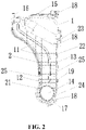
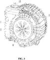
FIG. 2 is a structural diagram of a clothes drying device condenser assembly of the disclosure; - FIG. is a diagram of a clothes drying device including a condenser assembly of the disclosure.
- In the drawings: 1, condenser; 11, first condenser wall; 111, flat surface; 112, transition surface; 12, second condenser wall; 121, curved surface section; 122, flat surface section; 123, second curved surface section; 13, third condenser wall; 14, air inlet; 15, air outlet; 16, water inlet; 17, water outlet; 18, mounting ear; 19, sleeve; 2, fireproof structure; 21, first fireproof cover shell; 22, second fireproof cover shell; 23, fireproof cover shell connecting portion; 24, third fireproof cover shell; 25, stiffener; 3, outer cylinder; 4, motor.
- It should be noted that these drawings and descriptions are not to limit the conception of the disclosure in any way, but to illustrate the concept of the disclosure for the person skilled in the art by referring to specific embodiments.
- The technical scheme in the following embodiments will then be described clearly and completely with combination with the attached figures in order to make the purpose, technical scheme and advantages of the disclosure clearer. The following embodiments are used to illustrate the disclosure but are not used to limit the scope of the disclosure.
- In the following description, it should be noted that the terms "up", "down", "front", "back", "left", "right", "vertical", "inside", "outside" and etc. are based on the directions or positions shown in the attached figures. They are used to simplify the description, rather than to indicate that the device or element referred must have a specific direction or to be constructed or operated in a specific direction.
- And in the following description, it should be understood that the terms "installment" and "connection" should be treated according to generalized understanding. For example, they can be understood as fixed connection, detachable connection or integrated connection. Also, they can mean mechanical connection or electrical connection. They can also represent direct connection or indirect connection. The persons skilled in the art are able to understand the specific meaning of the above terms in the disclosure according to the specific situation.
- As shown in
FIG. 1 andFIG. 2 , a clothes drying device condenser assembly of the embodiment comprises acondenser 1, and at least one side wall of thecondenser 1 is provided with afireproof structure 2. The clothes drying device mainly includes clothes dryer, washing machine with clothes drying function and so on. - The
fireproof structure 2 is added on thecondenser 1 of the colthes dryer so that thecondenser 1 of the clothes drying device is prevented from being damaged by fire generated by fault of a motor of the clothes drying device. Moreover, because thecondenser 1 needs to be cooled and condensed during operation, heat conduction between thecondenser 1 and outside is able to be reduced by thefireproof structure 2 provided on thecondenser 1. Thefireproof structure 2 is also able to bring heat preservation and insulation effects to thecondenser 1. - A side wall of the
condenser 1 is provided with anair inlet 14, the side wall of the condenser where theair inlet 14 is located is afirst condenser wall 11, and at least one side wall adjacent to thefirst condenser wall 11 is provided with thefireproof structure 2. Among side walls adjacent to thefirst condenser wall 11, at least one side wall is provided with thefireproof structure 2, or it can be that one, two, three, four or all side walls are provided with thefireproof structure 2. Further, side walls adjacent to thefirst condenser wall 11 include asecond condenser wall 12 and athird condenser wall 13 oppositely arranged on both side of a ventilation direction, and thesecond condenser wall 12 and/or thethird condenser wall 13 is provided with thefireproof structure 2. - A lower end of the
first condenser wall 11 is provided with theair inlet 14, and anair outlet 15 is provided on an upper end of thecondenser 1. Thesecond condenser wall 12 includes an arc-shapedcurved surface section 121 extending from bottom to top, and thecurved surface section 121 is provided with thefireproof structure 2. An upper end of condenser is provided with awater inlet 16 at a position close to thesecond condenser wall 12, and awater outlet 17 is provided on a lower end of thecondenser 1. Extending from thecurved surface section 121 of thesecond condenser wall 12 to thewater inlet 16 forms aflat surface section 122, extending from thecurved surface section 121 of thesecond condenser wall 12 to thewater outlet 17 forms an arc-shaped secondcurved surface section 123, and theflat surface section 122 and the secondcurved surface section 123 are provided with thefireproof structure 2. - When installing the clothes drying device condenser assembly, the
second condenser wall 12 can be installed at a side adjacent to the motor of the clothes drying device. Thesecond condenser wall 12 is an arc-shapedcurved surface section 121 and is provided with thefireproof structure 2, which can not only prevent thecondenser 1 from being burnt out due to the motor catching fire, but also reduce noise of the motor and thecondenser 1 when the motor operates. - The
first condenser wall 11 is provided with thefireproof structure 2. Theair inlet 14 of the condenser is flanged to an outer surface of thefirst condenser wall 11 and extends to form asleeve 19, thesleeve 19 protrudes from thefirst condenser wall 11, and thesleeve 19 is provided with thefireproof structure 2. By providing thefireproof structure 2 on thefirst condenser wall 11 and thesleeve 19 at outer circumference of theair inlet 14, it is able to be prevented that flame spreads after the motor catches fire, burning other parts of thecondenser 1. - The
fireproof structure 2 is a fireproof and heat-insulating coating coated on thecondenser 1 or a condenser wall made of fireproof and heat-insulating material or a fireproof cover installed on thecondenser 1. - The fireproof structure is a fireproof cover, the fireproof cover comprises a first
fireproof cover shell 21 covering at least thesecond condenser wall 12 and a secondfireproof cover shell 22 covering thefirst condenser wall 11. Thecondenser 1 is provided with a fireproof covershell connecting portion 23, thethird condenser wall 13 is provided with a mountingear 18, and at least part of the fireproof covershell connecting portion 23 is arranged on the mountingear 18, buckled with a wall of the condenser. The fireproof covershell connecting portion 23 also includes a fireproof cover shell partly arranged on thethird condenser wall 13, and the fireproof cover shell arranged on thethird condenser wall 13 is used to connect the fireproof cover shell arranged on the mountingear 18 and the secondfireproof cover shell 22. The fireproof covershell connecting portion 23 is integrally connected with the firstfireproof cover shell 21 and the secondfireproof cover shell 22. - Preferably, the
condenser 1 is provided with the mountingear 18 at a position close to theair inlet 14, at least part of the fireproof covershell connecting portion 23 is arranged on the mountingear 18. The fireproof covershell connecting portion 23 is integrally connected with the firstfireproof cover shell 21 and the secondfireproof cover shell 22, buckled with the wall of the condenser. The fireproof cover forms a three-dimensional space by the firstfireproof cover shell 21 and the secondfireproof cover shell 22, the fireproof cover can be arranged on the wall of the condenser, and the fireproof covershell connecting portion 23, the firstfireproof cover shell 21 and the secondfireproof cover shell 22 can be clamped on thecondenser 1. The fireproof cover can be connected with the mountingear 18 of the condenser through the fireproof covershell connecting portion 23. The fireproof cover is detachably arranged on the wall of the condenser, and the condenser assembly has a simple structure and is convenient to disassemble. - The fireproof cover is also provided with a
stiffener 25, and thestiffener 25 is respectively arranged on the firstfireproof cover shell 21 in an up-and-down direction and/or on the secondfireproof cover shell 22 in an up-and-down direction along which thesecond condenser wall 12 extends. The fireproof cover is attached to a surface of the wall of the condenser. - The fireproof cover is a metal plate, a plastic material (such as PEI) with high rigidity, high heat resistance, flame resistance, high strength, excellent electrical performance, and wear resistance, or etc.
- As shown in
FIG. 1 to FIG. 3 , a clothes drying device of the embodiment includes the condenser assembly ofembodiment 1. The clothes drying device comprises anouter cylinder 3 andmotor 4 disposed on a bottom of the outer cylinder. A side wall of the condenser assembly provided with thefireproof structure 2 is disposed at a side adjacent to themotor 4. - A side wall of the condenser assembly adjacent to the
motor 4 is the arc-shaped curved surface section121, thecurved surface section 121 matches with an outer peripheral shape of themotor 4. Such structure and arrangement can reduce noise generated when themotor 4 is operating. A side wall of the condenser assembly with thefireproof structure 2 is arranged at a side adjacent to themotor 4, so that thecondenser 1 located at a side adjacent to themotor 4 is prevented from being burned out when themotor 4 catches fire. Moreover, because thecondenser 1 needs to be cooled and condensed during operation, heat conduction between thecondenser 1 and outside is able to be reduced by thefireproof structure 2 provided on thecondenser 1, bringing heat preservation and insulation effects to thecondenser 1. - A side wall of the
condenser 1 adjacent to the bottom of theouter cylinder 3 is provided with thefireproof structure 2. - Further, the side wall of the
condenser 1 adjacent to the bottom of theouter cylinder 3 comprises aflat surface 111 at a lower end and atransition surface 112 formed by bending and extending along theflat surface 111 towards a sidewall of theouter cylinder 3. Thefireproof structure 2 is at least provided on theflat surface 111. A wall of thecondenser 1 is provided with anair inlet 14 communicating with theouter cylinder 3, and theair inlet 14 is flanged to an outer surface of the wall of thecondenser 1 where theair inlet 14 is located and extends to form asleeve 19. Thesleeve 19 protrudes from the wall of thecondenser 1 where theair inlet 14 is located, and thesleeve 19 is provided with thefireproof structure 2. - Further, the fireproof structure is a fireproof cover, and the fireproof cover comprises a first
fireproof cover shell 21 and a secondfireproof cover shell 22 covering at least two adjacent side walls of thecondenser 1. Preferably, the firstfireproof cover shell 21 is provided at the side wall of thecondenser 1 adjacent to themotor 4, and the secondfireproof cover shell 22 is provided at the side wall of thecondenser 1 adjacent to the bottom of theouter cylinder 3. Thecondenser 1 is provided with a fireproof covershell connecting portion 23, at least one mountingear 18 is provided on an opposite surface to the side wall of thecondenser 1 adjacent to themotor 4, and at least part of the fireproof covershell connecting portion 23 is arranged on the mountingear 18. The fireproof covershell connecting portion 23 is integrally connected with the firstfireproof cover shell 21 and the secondfireproof cover shell 22, buckled with the wall of the condenser. - Preferably, the
sleeve 19 of thecondenser 1 is provided with a thirdfireproof cover shell 24, and the thirdfireproof cover shell 23 is integrally connected with the secondfireproof cover shell 22. The mountingear 18 of the condenser and the fireproof covershell connecting portion 23 are coordinated and connected with theouter cylinder 3. Preferably, the fireproof covershell connecting portion 23 and the mountingear 18 of the condenser are connected with theouter cylinder 3 by screws or other fasteners. - The condenser assembly has the function of preventing the
condenser 1 from being burned out due to themotor 4 which breaks down and catches fire. Also, the condenser assembly is detachably connected to the clothes drying device, which is convenient to disassemble and has a simple structure. - The above description is just used to illustrate some more practical embodiments of the disclosure but is not the limitation of the disclosure in any way. Although the disclosure has been enclosed as the above embodiments, they are not used to limit the disclosure. Within the technical scheme of the disclosure, any person skilled in the art should be able to make some changes or modifications based on the above techniques to obtain other embodiments with equal benefits. But any simple changes, equivalent changes or modifications, made to the above embodiments according to the technical substance within the technical scheme of the disclosure, still belong to the protection range of the disclosure.
Claims (15)
- A clothes drying device condenser assembly comprising a condenser, characterized in that at least a side wall of the condenser is provided with a fireproof structure.
- The clothes drying device condenser assembly according to claim 1, characterized in that the side wall of the condenser is provided with an air inlet, the side wall of the condenser where the air inlet is located is a first condenser wall, and at least one side wall adjacent to the first condenser wall is provided with the fireproof structure.
- The clothes drying device condenser assembly according to claim 2, characterized in that side walls adjacent to the first condenser wall include a second condenser wall and a third condenser wall oppositely arranged on both sides of a ventilation direction, and the second condenser wall and/or the third condenser wall is provided with the fireproof structure.
- The clothes drying device condenser assembly according to claim 3, characterized in that a lower end of the first condenser wall is provided with the air inlet, an air outlet is provided on an upper end of the condenser, the second condenser wall includes an arc-shaped curved surface section extending from bottom to top, and the curved surface section is provided with the fireproof structure.
- The clothes drying device condenser assembly according to claim 4, characterized in that the upper end of the condenser is provided with a water inlet at a position close to the second condenser wall, a water outlet is provided on a lower end of the condenser, a flat surface section is formed by extending from the curved surface section of the second condenser wall to the water inlet, an arc-shaped second curved surface section is formed by extending from the curved surface section of the second condenser wall to the water outlet, and the flat surface section and the second curved surface section are provided with the fireproof structure.
- The clothes drying device condenser assembly according to any one of claims 2 to 5, characterized in that the first condenser wall is provided with the fireproof structure.
- The clothes drying device condenser assembly according to claim 6, characterized in that the air inlet of the condenser is flanged to an outer surface of the first condenser wall and extends to form a sleeve, the sleeve protrudes from the first condenser wall, and the sleeve is provided with the fireproof structure.
- The clothes drying device condenser assembly according to any one of claims 1 to 7, characterized in that the fireproof structure is a fireproof and heat-insulating coating coated on the condenser or a condenser wall made of fireproof and heat-insulating material or a fireproof cover installed on the condenser.
- The clothes drying device condenser assembly according to claim 6 or 7, characterized in that the fireproof structure is a fireproof cover, the fireproof cover comprises a first fireproof cover shell covering at least the second condenser wall and a second fireproof cover shell covering the first condenser wall.
- The clothes drying device condenser assembly according to claim 9, characterized in that the condenser is provided with a fireproof cover shell connecting portion, the third condenser wall is provided with a mounting ear, at least part of the fireproof cover shell connecting portion is arranged on the mounting ear, and the fireproof cover shell connecting portion is integrally connected with the first fireproof cover shell and the second fireproof cover shell, covering the side wall of the condenser;
preferably, the mounting ear is provided on the condenser close to the air inlet. - A clothes drying device, including the clothes drying device condenser assembly according to any one of claim 1 to 10, comprises an outer cylinder and a motor disposed on a bottom of the outer cylinder, characterized in that a side wall of the condenser assembly provided with the fireproof structure is adjacent to the motor.
- The clothes drying device according to claim 11, characterized in that the side wall of the condenser adjacent to the bottom of the outer cylinder is provided with the fireproof structure.
- The clothes drying device according to claim 12, characterized in that the side wall of the condenser adjacent to the bottom of the outer cylinder comprises a flat surface at a lower end and a transition surface formed by bending and extending along the flat surface towards a sidewall of the outer cylinder, and the fireproof structure is at least provided on the flat surface.
- The clothes drying device according to claim 13, characterized in that the side wall of the condenser is provided with the air inlet communicating with the outer cylinder, the air inlet is flanged to the outer surface of the side wall of the condenser where the air inlet is located and extends to form the sleeve, the sleeve protrudes from the side wall of the condenser where the air inlet is located, and the sleeve is provided with the fireproof structure.
- The clothes drying device according to any one of claim 12 to 14, characterized in thatthe fireproof structure is the fireproof cover, and the fireproof cover comprises the first fireproof cover shell and the second fireproof cover shell covering at least two adjacent side walls of the condenser;preferably, the condenser is provided with the fireproof cover shell connecting portion, at least one mounting ear is provided on an opposite surface to the side wall of the condenser adjacent to the motor, at least part of the fireproof cover shell connecting portion is arranged on the mounting ear, and the fireproof cover shell connecting portion is integrally connected with the first fireproof cover shell and the second fireproof cover shell, covering the side wall of the condenser;preferably, the mounting ear of the condenser and the fireproof cover shell connecting portion are coordinated and connected with the outer cylinder.
Applications Claiming Priority (2)
| Application Number | Priority Date | Filing Date | Title |
|---|---|---|---|
| CN201910574767.8A CN110292731B (en) | 2019-06-28 | 2019-06-28 | A condenser component of clothes drying equipment and clothes drying equipment |
| PCT/CN2020/096088 WO2020259335A1 (en) | 2019-06-28 | 2020-06-15 | Clothes dryer condenser assembly and clothes dryer |
Publications (2)
| Publication Number | Publication Date |
|---|---|
| EP3992354A1 true EP3992354A1 (en) | 2022-05-04 |
| EP3992354A4 EP3992354A4 (en) | 2022-08-17 |
Family
ID=68029384
Family Applications (1)
| Application Number | Title | Priority Date | Filing Date |
|---|---|---|---|
| EP20832703.1A Withdrawn EP3992354A4 (en) | 2019-06-28 | 2020-06-15 | CONDENSER ARRANGEMENT FOR CLOTHES DRYERS AND TRUNK DRYERS |
Country Status (3)
| Country | Link |
|---|---|
| EP (1) | EP3992354A4 (en) |
| CN (1) | CN110292731B (en) |
| WO (1) | WO2020259335A1 (en) |
Cited By (1)
| Publication number | Priority date | Publication date | Assignee | Title |
|---|---|---|---|---|
| CN115897120A (en) * | 2022-11-18 | 2023-04-04 | 海信冰箱有限公司 | Drum washing machine |
Families Citing this family (1)
| Publication number | Priority date | Publication date | Assignee | Title |
|---|---|---|---|---|
| CN110292731B (en) * | 2019-06-28 | 2023-09-15 | 合肥海尔滚筒洗衣机有限公司 | A condenser component of clothes drying equipment and clothes drying equipment |
Family Cites Families (17)
| Publication number | Priority date | Publication date | Assignee | Title |
|---|---|---|---|---|
| KR100587323B1 (en) * | 2003-04-28 | 2006-06-08 | 엘지전자 주식회사 | Sensor mounting structure of automatic dryer |
| KR20050101660A (en) * | 2004-04-19 | 2005-10-25 | 엘지전자 주식회사 | Drum type washing machine with laundry drying function |
| CN200988913Y (en) * | 2006-12-20 | 2007-12-12 | 杭州松下家用电器有限公司 | Program controller cover for washing machine |
| JP5266982B2 (en) * | 2008-09-04 | 2013-08-21 | パナソニック株式会社 | Air conditioning unit and assembling method thereof |
| ITRN20100080A1 (en) * | 2010-12-22 | 2012-06-23 | Indesit Co Spa | APPLIANCE |
| TW201325421A (en) * | 2011-12-15 | 2013-06-16 | Hon Hai Prec Ind Co Ltd | Cooling system |
| CN104233737B (en) * | 2013-06-21 | 2018-05-01 | 青岛海尔洗衣机有限公司 | A kind of water condenser and washing-drying integral machine and clothes-drying method |
| CN203559277U (en) * | 2013-07-17 | 2014-04-23 | 海尔集团公司 | Fire resisting structure for motor of washing machine |
| CN203893006U (en) * | 2014-06-05 | 2014-10-22 | 立达信绿色照明股份有限公司 | Fireproof down lamp |
| CN107815835B (en) * | 2016-09-13 | 2020-04-03 | 青岛海尔滚筒洗衣机有限公司 | A high-efficiency condenser and washing machine with the same |
| CN106653287A (en) * | 2016-11-28 | 2017-05-10 | 国家电网公司 | Fireproof transformer outer cover |
| CN106963317B (en) * | 2017-05-08 | 2020-01-10 | 佛山市顺德区美的洗涤电器制造有限公司 | Base and dish washing machine |
| CN206830484U (en) * | 2017-05-31 | 2018-01-02 | 浙江志江风机有限公司 | A kind of smoke exhaust fan of fire-fighting |
| CN109868616A (en) * | 2017-12-01 | 2019-06-11 | 青岛海尔洗衣机有限公司 | A kind of washing machine |
| CN208038824U (en) * | 2018-01-16 | 2018-11-02 | 青岛海尔滚筒洗衣机有限公司 | The cleaning device of roller washing machine |
| CN110292731B (en) * | 2019-06-28 | 2023-09-15 | 合肥海尔滚筒洗衣机有限公司 | A condenser component of clothes drying equipment and clothes drying equipment |
| CN210750985U (en) * | 2019-06-28 | 2020-06-16 | 重庆海尔滚筒洗衣机有限公司 | Condenser assembly of clothes drying equipment and clothes drying equipment |
-
2019
- 2019-06-28 CN CN201910574767.8A patent/CN110292731B/en active Active
-
2020
- 2020-06-15 EP EP20832703.1A patent/EP3992354A4/en not_active Withdrawn
- 2020-06-15 WO PCT/CN2020/096088 patent/WO2020259335A1/en not_active Ceased
Cited By (1)
| Publication number | Priority date | Publication date | Assignee | Title |
|---|---|---|---|---|
| CN115897120A (en) * | 2022-11-18 | 2023-04-04 | 海信冰箱有限公司 | Drum washing machine |
Also Published As
| Publication number | Publication date |
|---|---|
| WO2020259335A1 (en) | 2020-12-30 |
| EP3992354A4 (en) | 2022-08-17 |
| CN110292731A (en) | 2019-10-01 |
| CN110292731B (en) | 2023-09-15 |
Similar Documents
| Publication | Publication Date | Title |
|---|---|---|
| EP3026168B1 (en) | Clothes drying device | |
| CN106533134B (en) | A kind of self-enclosed heat dissipation frequency-charger cabinet | |
| CN222187153U (en) | Air conditioning cabinet | |
| CN110292731B (en) | A condenser component of clothes drying equipment and clothes drying equipment | |
| CN116725381A (en) | cooking device | |
| CN209958109U (en) | Clothes treating apparatus | |
| EP2435625B1 (en) | Clothes drying apparatus | |
| CN210750985U (en) | Condenser assembly of clothes drying equipment and clothes drying equipment | |
| CN112080912A (en) | A clothing treatment device | |
| US20170342648A1 (en) | Heat Pump Mounting Box And Heat Pump Drier Or Heat Pump Washer-Drier Machine | |
| TWI572833B (en) | Heating Ventilator | |
| CN214782735U (en) | Steam generator, steam generator assembly and laundry treating apparatus | |
| CN207815488U (en) | A kind of waterproof fan heater | |
| CN215271034U (en) | Nozzle structure and hair dryer | |
| CN109724248B (en) | water heater | |
| JP2826063B2 (en) | Air fan | |
| CN222349359U (en) | Ironing equipment | |
| JP4610809B2 (en) | Blower | |
| CN216838663U (en) | Drying and heating structure of washing machine | |
| EP3252222B1 (en) | Heat pump drying or washing-drying machine | |
| CN219868217U (en) | Electric appliance box of air conditioner outdoor unit and air conditioner outdoor unit | |
| WO2020108377A1 (en) | Interface installing structure, interface assembly, and air conditioner | |
| CN224001681U (en) | Clothes drying box with waterproof function | |
| CN221877492U (en) | Drying devices and clothing processing equipment | |
| JPS5838356Y2 (en) | Hot air machine |
Legal Events
| Date | Code | Title | Description |
|---|---|---|---|
| STAA | Information on the status of an ep patent application or granted ep patent |
Free format text: STATUS: THE INTERNATIONAL PUBLICATION HAS BEEN MADE |
|
| PUAI | Public reference made under article 153(3) epc to a published international application that has entered the european phase |
Free format text: ORIGINAL CODE: 0009012 |
|
| STAA | Information on the status of an ep patent application or granted ep patent |
Free format text: STATUS: REQUEST FOR EXAMINATION WAS MADE |
|
| 17P | Request for examination filed |
Effective date: 20220104 |
|
| AK | Designated contracting states |
Kind code of ref document: A1 Designated state(s): AL AT BE BG CH CY CZ DE DK EE ES FI FR GB GR HR HU IE IS IT LI LT LU LV MC MK MT NL NO PL PT RO RS SE SI SK SM TR |
|
| A4 | Supplementary search report drawn up and despatched |
Effective date: 20220720 |
|
| RIC1 | Information provided on ipc code assigned before grant |
Ipc: A62C 3/16 20060101ALI20220714BHEP Ipc: D06F 58/24 20060101AFI20220714BHEP |
|
| DAV | Request for validation of the european patent (deleted) | ||
| DAX | Request for extension of the european patent (deleted) | ||
| STAA | Information on the status of an ep patent application or granted ep patent |
Free format text: STATUS: THE APPLICATION IS DEEMED TO BE WITHDRAWN |
|
| 18D | Application deemed to be withdrawn |
Effective date: 20230221 |