EP3992347A1 - Laundry treatment apparatus - Google Patents
Laundry treatment apparatus Download PDFInfo
- Publication number
- EP3992347A1 EP3992347A1 EP20831324.7A EP20831324A EP3992347A1 EP 3992347 A1 EP3992347 A1 EP 3992347A1 EP 20831324 A EP20831324 A EP 20831324A EP 3992347 A1 EP3992347 A1 EP 3992347A1
- Authority
- EP
- European Patent Office
- Prior art keywords
- laundry processing
- receiving member
- feeding device
- processing agent
- agent feeding
- Prior art date
- Legal status (The legal status is an assumption and is not a legal conclusion. Google has not performed a legal analysis and makes no representation as to the accuracy of the status listed.)
- Granted
Links
Images



Classifications
-
- D—TEXTILES; PAPER
- D06—TREATMENT OF TEXTILES OR THE LIKE; LAUNDERING; FLEXIBLE MATERIALS NOT OTHERWISE PROVIDED FOR
- D06F—LAUNDERING, DRYING, IRONING, PRESSING OR FOLDING TEXTILE ARTICLES
- D06F39/00—Details of washing machines not specific to a single type of machines covered by groups D06F9/00 - D06F27/00
- D06F39/02—Devices for adding soap or other washing agents
-
- D—TEXTILES; PAPER
- D06—TREATMENT OF TEXTILES OR THE LIKE; LAUNDERING; FLEXIBLE MATERIALS NOT OTHERWISE PROVIDED FOR
- D06F—LAUNDERING, DRYING, IRONING, PRESSING OR FOLDING TEXTILE ARTICLES
- D06F37/00—Details specific to washing machines covered by groups D06F21/00 - D06F25/00
- D06F37/42—Safety arrangements, e.g. for stopping rotation of the receptacle upon opening of the casing door
Definitions
- the present invention relates to the technical field of laundry processing, and particularly, to a laundry processing apparatus.
- Laundry processing apparatuses are machines for washing, spin-drying, dry-cleaning and/or heat-drying laundry.
- Common laundry processing apparatuses include washing machines, shoe washing machines, laundry dryers, dry-cleaning machines, and combo washer/dryer machines.
- a detergent/washing powder is often added to the water before the laundry is washed, such that stains and/or oil stains on the laundry are removed using surfactants.
- a washing machine is usually provided with a detergent feeding device.
- a detergent/washing powder can be fed into a washing chamber of the washing machine through the detergent feeding device.
- the detergent feeding device is generally of a drawer type, and can slide on a sliding rail provided on a body of the washing machine.
- the detergent feeding device may fall off from the sliding rail, posing safety risks.
- the present invention provides a laundry processing apparatus, comprising: a locking device, a receiving member and a laundry processing agent feeding device provided in the receiving member, wherein the laundry processing agent feeding device is slidably connected to the receiving member, the locking device is provided between the receiving member and the laundry processing agent feeding device, and the locking device is configured for preventing the laundry processing agent feeding device from being disengaged from the receiving member in a locked state and is further configured for allowing the laundry processing agent feeding device to be disengaged from the receiving member in an unlocked state.
- the locking device comprises a first locking structure provided at a bottom or a side portion of the receiving member and a second locking structure correspondingly provided at a bottom or a side portion of the laundry processing agent feeding device; in the locked state, the first and second locking structures cooperate to prevent the laundry processing agent feeding device from being disengaged from the receiving member, and in the unlocked state, the first and second locking structures separate from each other to allow the laundry processing agent feeding device to come out of the receiving member.
- the first locking structure is a baffle
- the second locking structure comprises an elastic plate and a stopper fixed to or integrated with the elastic plate
- the baffle is fixed to or integrated with an inner sidewall of the receiving member
- the elastic plate is fixed to or integrated with an outer sidewall of the laundry processing agent feeding device; in the locked state, the stopper abuts against the baffle under the action of the elastic plate to prevent the laundry processing agent feeding device from being disengaged from the receiving member, and in the unlocked state, the elastic plate drives the stopper to move through elastic deformation and thus separates the stopper and the baffle, allowing the laundry processing agent feeding device to be disengaged from the receiving member.
- the stopper is provided with a stopping surface substantially perpendicular to the elastic plate, and in the locked state, the stopping surface abuts against the baffle to prevent the laundry processing agent feeding device from being disengaged from the receiving member.
- the stopper is further provided with an arc-shaped or flat sliding surface obliquely disposed relative to the elastic plate, such that the laundry processing agent feeding device is smoothly inserted into the receiving member during assembly.
- the stopper is a wedge having a shape of a right triangle or a right trapezoid, a surface where one of the legs of the right triangle or the perpendicular leg of the right trapezoid is located constitutes the stopping surface, and a surface where the hypotenuse of the right triangle or the oblique leg of the right trapezoid is located constitutes the sliding surface.
- the laundry processing agent feeding device comprises a storage container, a feeding container and a guiding tube
- the storage container is fixed in the receiving member
- the feeding container is slidably connected to the receiving member
- one end of the guiding tube communicates with the feeding container
- the other end of the guiding tube is inserted into the storage container
- the length of the guiding tube is configured such that the guiding tube does not come out of the storage container when the feeding container moves away from the storage container.
- the storage container is provided with a directing structure, and the other end of the guiding tube is inserted into the storage container through the directing structure.
- the directing structure is a directing joint formed on an outer wall of the storage container.
- the laundry processing apparatus is a washing machine, and/or the laundry processing agent feeding device is a device for feeding a detergent or a care agent, and/or the receiving member is a receiving box.
- providing a locking device between the laundry processing agent feeding device and the receiving member can prevent the laundry processing agent feeding device from being disengaged from the receiving member, thereby improving the safety of the laundry processing apparatus.
- the locking device has two states: a locked state and an unlocked state. In normal use, the locking device is in the locked state and can prevent the laundry processing agent feeding device from being disengaged from the receiving member, eliminating potential safety risks; when the laundry processing agent feeding device requires cleaning or maintenance, the locking device turns to the unlocked state from the locked state, such that the laundry processing agent feeding device can be taken out of the receiving member for operations such as cleaning or maintenance, thus improving the user experience.
- the first locking structure at the bottom or the side portion of the receiving member and providing the second locking structure at the bottom or the side portion of the laundry processing agent feeding device it is convenient for a user, when taking the laundry processing agent feeding device out of the receiving member, to hold the laundry processing agent feeding device while separating the first and the second locking structures, so as to take the laundry processing agent feeding device out of the receiving member; such configuration can also prevent the laundry processing agent feeding device from falling off from the user's hands, thus featuring a convenient and safe operation and improved user experience.
- the first locking structure is a baffle
- the second locking structure comprises an elastic plate and a stopper provided on the elastic plate
- the baffle is provided on an inner sidewall of the receiving member
- the elastic plate is provided on an outer sidewall of the laundry processing agent feeding device.
- the stopper abuts against the baffle under the action of the elastic plate to prevent the laundry processing agent feeding device from being disengaged from the receiving member, eliminating potential safety risks.
- the stopper is further provided with an arc-shaped or flat sliding surface obliquely disposed relative to the elastic plate, such that the laundry processing agent feeding device is smoothly inserted into the receiving member during assembly.
- Such configuration can improve both the assembly efficiency of the laundry processing apparatus and the user experience.
- the laundry processing agent feeding device is configured as a split structure, where the storage container and the feeding container are separably arranged, and only the feeding container is slidably connected to the receiving member, such that when adding the laundry processing agent, the user only needs to pull out the feeding container but not the storage container, which is easy and convenient, thereby improving the user experience.
- a guiding tube is provided between the feeding container and the storage container and the other end of the guiding tube is inserted into the storage container, when the feeding container is pulled out, the guiding tube moves along with the feeding container, but the other end of the guiding tube is not disengaged from the storage container, such that the feeding container always communicates with the storage container through the guiding tube.
- the laundry processing agent can be delivered to the storage container through the guiding tube when the laundry processing agent is fed into the feeding container.
- the guiding tube is inserted into the storage container through a directing structure provided on the storage container.
- the guiding tube is directed by the directing structure, so as to prevent guiding tube from shifting during the movement, thus improving the reliability of the laundry processing agent feeding device.
- the terms “provide”, “dispose”, “connect” and “communicate” are to be construed broadly and, for example, may be a fixed connection, a detachable connection, or an integral connection; may be a mechanical or electrical connection; or may be a direct connection or an indirect connection through a medium, or may be an intercommunication between two elements.
- the specific meanings of the aforementioned terms in the present invention can be understood according to specific conditions.
- the present invention provides a washing machine intended to prevent the laundry processing agent feeding device from falling off from the washing machine.
- the washing machine disclosed herein comprises a locking device, a receiving member 1 and a laundry processing agent feeding device provided in the receiving member 1, wherein the laundry processing agent feeding device is slidably connected to the receiving member 1, the locking device is provided between the receiving member 1 and the laundry processing agent feeding device, and the locking device is configured for preventing the laundry processing agent feeding device from being disengaged from the receiving member 1 in a locked state and is further configured for allowing the laundry processing agent feeding device to be disengaged from the receiving member 1 in an unlocked state.
- the locking device has two states: a locked state and an unlocked state.
- the locking device In normal use, the locking device is in the locked state and can prevent the laundry processing agent feeding device from being disengaged from the receiving member 1, eliminating potential safety risks; when the laundry processing agent feeding device requires cleaning or maintenance, the locking device turns to the unlocked state from the locked state, such that the laundry processing agent feeding device can be taken out of the receiving member 1 for operations such as cleaning or maintenance.
- the receiving member 1 is a receiving box, and the laundry processing agent feeding device is provided in the receiving box and is slidably connected to the receiving box.
- the receiving member 1 can be configured as a receiving barrel, a receiving tank, etc. Such adjustments and modifications can be made to the specific configuration of the receiving member 1 without departing from the principles and scope of the present invention, and shall fall within the protection scope of the present invention.
- the laundry processing agent may be a detergent, and the laundry processing agent feeding device is a device for feeding the detergent; or the laundry processing agent may also be a care agent, and the laundry processing agent feeding device is a device for feeding the care agent.
- the laundry processing agent feeding device is a device for feeding the care agent.
- the locking device comprises a first locking structure 2 provided at a bottom or a side portion of the receiving member 1 and a second locking structure 3 correspondingly provided at a bottom or a side portion of the laundry processing agent feeding device; in the locked state, the first locking structure 2 and the second locking structure 3 cooperate to prevent the laundry processing agent feeding device from being disengaged from the receiving member 1, and in the unlocked state, the first locking structure 2 and the second locking structure 3 separate from each other to allow the laundry processing agent feeding device to be disengaged from the receiving member 1.
- the first locking structure 2 may be provided at the bottom of the receiving member 1, and the second locking structure 3 may be correspondingly provided at the bottom of the laundry processing agent feeding device; or alternatively, the first locking structure 2 may be provided at the side portion of the receiving member 1, and the second locking structure 3 may be correspondingly provided at the side portion of the laundry processing agent feeding device.
- the first locking structure 2 is a baffle 2
- the second locking structure 3 comprises an elastic plate 31 and a stopper 32 fixed to or integrated with the elastic plate 31,
- the baffle 2 is fixed to or integrated with an inner sidewall of the receiving member 1
- the elastic plate 31 is fixed to or integrated with an outer sidewall of the laundry processing agent feeding device.
- the stopper 32 abuts against the baffle 2 under the action of the elastic plate 31 to prevent the laundry processing agent feeding device from being disengaged from the receiving member 1, and in the unlocked state, the elastic plate 31 drives the stopper 32 to move through elastic deformation and thus separates the stopper 32 and the baffle 2, allowing the laundry processing agent feeding device to be disengaged from the receiving member 1.
- the locking device is in the locked state.
- the laundry processing agent feeding device is pulled out (leftwards as shown in the figures) by a user, the laundry processing agent feeding device slides to a protruding position (referring to a position where the laundry processing agent can be fed into the laundry processing agent feeding device), and the stopper 32 abuts against the baffle 2 to stop the laundry processing agent feeding device from continuously sliding leftwards, thus preventing the laundry processing agent feeding device from being disengaged from the receiving member 1.
- the elastic plate 31 is pressed inwards by hand, the elastic plate 31 elastically deforms and drives the stopper 32 to move towards the laundry processing agent feeding device to separate the stopper 32 and the baffle 2.
- the locking device turns to the unlocked state from the locked state, such that the laundry processing agent feeding device can be taken out of the receiving member 1 for operations such as cleaning or maintenance.
- the first locking structure 2 may be configured as a rib, and correspondingly the second locking structure 3 is configured as an elastic plate 31 provided with a ledge; or alternatively, the first locking structure 2 may be configured as a stopper, and correspondingly the second locking structure 3 is configured as an L-shaped baffle.
- first locking structure 2 and the second locking structure 3 may flexibly adjust the specific configurations of the first locking structure 2 and the second locking structure 3 in practice, as long as the first locking structure 2 and the second locking structure 3 can cooperate in the locked state to prevent the laundry processing agent feeding device from being disengaged from the receiving member 1, and separate from each other in the unlocked state to allow the laundry processing agent feeding device to be disengaged from the receiving member 1.
- the stopper 32 is provided with a stopping surface 321 substantially perpendicular to the elastic plate 31, and in the locked state, the stopping surface 321 abuts against the baffle 2 to prevent the laundry processing agent feeding device from being disengaged from the receiving member 1.
- the stopping surface 321 is preferably perpendicular to the elastic plate 31, but certainly, may also be slightly inclined to the left or right, as long as the stopping surface 321 can abut against the baffle 2 in the locked state to prevent the laundry processing agent feeding device from being disengaged from the receiving member 1.
- the stopper 32 is further provided with an arc-shaped or flat sliding surface 322 obliquely disposed relative to the elastic plate 31, such that the laundry processing agent feeding device is smoothly inserted into the receiving member 1 during assembly.
- the stopper 32 is a wedge having a shape of a right triangle (for example, the stopper 32 in FIG. 5 ), a surface where one of the legs of the right triangle is located constitutes the stopping surface 321, and a surface where the hypotenuse of the right triangle is located constitutes the sliding surface 322.
- the stopper 32 is a wedge having a shape of a right trapezoid (for example, the stopper 32 in FIG.
- a surface where the perpendicular leg of the right trapezoid is located constitutes the stopping surface 321
- a surface where the oblique leg of the right trapezoid is located constitutes the sliding surface 322.
- the sliding surface 322 and the elastic plate 31 enable a smooth transition, which is more favorable for smoothly inserting the laundry processing agent feeding device into the receiving member 1.
- the stopper 32 may be configured in other shapes, such as a conical shape and a pyramidal shape. Such adjustments and modifications can be made to the shape of the stopper 32 without departing from the principles and scope of the present invention, and shall fall within the protection scope of the present invention.
- the laundry processing agent feeding device comprises a storage container 4, a feeding container 5 and a guiding tube 6, the storage container 4 is fixed in the receiving member 1, the feeding container 5 is slidably connected to the receiving member 1, one end of the guiding tube 6 communicates with the feeding container 5, the other end of the guiding tube 6 is inserted into the storage container 4, and the length of the guiding tube 6 is configured such that the other end of the guiding tube 6 is not disengaged from the storage container 4 when the feeding container 5 moves away from the storage container 4.
- the laundry processing agent feeding device is configured as a split structure, where the storage container 4 and the feeding container 5 are separably arranged, and only the feeding container 5 is slidably connected to the receiving member 1, such that when adding the laundry processing agent, the user only needs to pull out the feeding container 5 but not the storage container 4.
- the feeding container 5 communicates with the storage container 4 via the guiding tube 6, and a right end of the guiding tube 6 is inserted into the storage container 4.
- the guiding tube 6 moves along with the feeding container 5, but the right end of the guiding tube 6 is not disengaged from the storage container 4, such that the laundry processing agent fed into the feeding container 5 can be delivered into the storage container 4 through the guiding tube 6.
- the user pushes the feeding container 5 and the guiding tube 6 back into the receiving member 1, and a right portion of the guiding tube 6 is inserted into the storage container 4 again.
- the elastic plate 31 is fixed to or integrated with an outer sidewall of the feeding container 5.
- the stopper 32 abuts against the baffle 2 to prevent the feeding container 5 from being disengaged from the receiving member 1.
- the elastic plate 31 is pressed inwards by hand, the elastic plate 31 elastically deforms and drives the stopper 32 to move towards the feeding container 5 to separate the stopper 32 and the baffle 2. At this time, the feeding container 5 can be taken out of the receiving member 1.
- the feeding container 5 is provided with two feeding cavities 51, of which one is a detergent feeding cavity and the other is a care agent feeding cavity.
- the storage container 4 is provided with two storage cavities: a detergent storage cavity communicated with the detergent feeding cavity through a guiding tube 6, and a care agent storage cavity communicated with the care agent feeding cavity through another guiding tube 6.
- the number of the feeding cavities 51 is not limited to two as described above.
- the number of the feeding cavities 51 can be one or three. Such adjustments and modifications can be made to the number of the feeding cavities 51 without departing from the principles and scope of the present invention, and shall fall within the protection scope of the present invention.
- laundry processing agent feeding device may also be configured as an integral structure, where the storage container 4 is fixed to or integrated with the feeding container 5.
- the guiding tube 6 can be eliminated.
- the storage container 4 is provided with a directing structure 41, and the other end of the guiding tube 6 is inserted into the storage container 4 through the directing structure 41.
- the directing structure 41 is a directing joint 41 formed on an outer wall of the storage container 4.
- the right end of the guiding tube 6 is inserted into the storage container 4 through the directing joint 41.
- the directing joint 41 directs the guiding tube 6 when the guiding tube 6 moves along with the feeding container 5.
- the directing structure 41 can be configured as other structures such as directing ribs or directing tubes. Such adjustments and modifications can be made to the specific configuration of the directing structure 41 without departing from the principles and scope of the present invention, and shall fall within the protection scope of the present invention.
Landscapes
- Engineering & Computer Science (AREA)
- Textile Engineering (AREA)
- Detail Structures Of Washing Machines And Dryers (AREA)
- Accessory Of Washing/Drying Machine, Commercial Washing/Drying Machine, Other Washing/Drying Machine (AREA)
Abstract
Description
- The present invention relates to the technical field of laundry processing, and particularly, to a laundry processing apparatus.
- Laundry processing apparatuses are machines for washing, spin-drying, dry-cleaning and/or heat-drying laundry. Common laundry processing apparatuses include washing machines, shoe washing machines, laundry dryers, dry-cleaning machines, and combo washer/dryer machines. To ensure the washing effect of the laundry, for example, in a washing machine, a detergent/washing powder is often added to the water before the laundry is washed, such that stains and/or oil stains on the laundry are removed using surfactants.
- In the prior art, a washing machine is usually provided with a detergent feeding device. A detergent/washing powder can be fed into a washing chamber of the washing machine through the detergent feeding device. The detergent feeding device is generally of a drawer type, and can slide on a sliding rail provided on a body of the washing machine. However, when the detergent is fed, the detergent feeding device may fall off from the sliding rail, posing safety risks.
- Therefore, there is a need in the art for a new laundry processing apparatus to solve the above problem.
- In order to solve the above-mentioned problem of the prior art that the laundry processing agent feeding device in an existing laundry processing apparatus may have risks of falling off from the laundry processing apparatus, the present invention provides a laundry processing apparatus, comprising: a locking device, a receiving member and a laundry processing agent feeding device provided in the receiving member, wherein the laundry processing agent feeding device is slidably connected to the receiving member, the locking device is provided between the receiving member and the laundry processing agent feeding device, and the locking device is configured for preventing the laundry processing agent feeding device from being disengaged from the receiving member in a locked state and is further configured for allowing the laundry processing agent feeding device to be disengaged from the receiving member in an unlocked state.
- In one preferred embodiment of the laundry processing apparatus, the locking device comprises a first locking structure provided at a bottom or a side portion of the receiving member and a second locking structure correspondingly provided at a bottom or a side portion of the laundry processing agent feeding device; in the locked state, the first and second locking structures cooperate to prevent the laundry processing agent feeding device from being disengaged from the receiving member, and in the unlocked state, the first and second locking structures separate from each other to allow the laundry processing agent feeding device to come out of the receiving member.
- In one preferred embodiment of the laundry processing apparatus, the first locking structure is a baffle, the second locking structure comprises an elastic plate and a stopper fixed to or integrated with the elastic plate, the baffle is fixed to or integrated with an inner sidewall of the receiving member, and the elastic plate is fixed to or integrated with an outer sidewall of the laundry processing agent feeding device; in the locked state, the stopper abuts against the baffle under the action of the elastic plate to prevent the laundry processing agent feeding device from being disengaged from the receiving member, and in the unlocked state, the elastic plate drives the stopper to move through elastic deformation and thus separates the stopper and the baffle, allowing the laundry processing agent feeding device to be disengaged from the receiving member.
- In one preferred embodiment of the laundry processing apparatus, the stopper is provided with a stopping surface substantially perpendicular to the elastic plate, and in the locked state, the stopping surface abuts against the baffle to prevent the laundry processing agent feeding device from being disengaged from the receiving member.
- In one preferred embodiment of the laundry processing apparatus, the stopper is further provided with an arc-shaped or flat sliding surface obliquely disposed relative to the elastic plate, such that the laundry processing agent feeding device is smoothly inserted into the receiving member during assembly.
- In one preferred embodiment of the laundry processing apparatus, the stopper is a wedge having a shape of a right triangle or a right trapezoid, a surface where one of the legs of the right triangle or the perpendicular leg of the right trapezoid is located constitutes the stopping surface, and a surface where the hypotenuse of the right triangle or the oblique leg of the right trapezoid is located constitutes the sliding surface.
- In one preferred embodiment of the laundry processing apparatus, the laundry processing agent feeding device comprises a storage container, a feeding container and a guiding tube, the storage container is fixed in the receiving member, the feeding container is slidably connected to the receiving member, one end of the guiding tube communicates with the feeding container, the other end of the guiding tube is inserted into the storage container, and the length of the guiding tube is configured such that the guiding tube does not come out of the storage container when the feeding container moves away from the storage container.
- In one preferred embodiment of the laundry processing apparatus, the storage container is provided with a directing structure, and the other end of the guiding tube is inserted into the storage container through the directing structure.
- In one preferred embodiment of the laundry processing apparatus, the directing structure is a directing joint formed on an outer wall of the storage container.
- In one preferred embodiment of the laundry processing apparatus, the laundry processing apparatus is a washing machine, and/or the laundry processing agent feeding device is a device for feeding a detergent or a care agent, and/or the receiving member is a receiving box.
- It can be appreciated by those skilled in the art that in preferred embodiments of the present invention, providing a locking device between the laundry processing agent feeding device and the receiving member can prevent the laundry processing agent feeding device from being disengaged from the receiving member, thereby improving the safety of the laundry processing apparatus. The locking device has two states: a locked state and an unlocked state. In normal use, the locking device is in the locked state and can prevent the laundry processing agent feeding device from being disengaged from the receiving member, eliminating potential safety risks; when the laundry processing agent feeding device requires cleaning or maintenance, the locking device turns to the unlocked state from the locked state, such that the laundry processing agent feeding device can be taken out of the receiving member for operations such as cleaning or maintenance, thus improving the user experience.
- Further, by providing the first locking structure at the bottom or the side portion of the receiving member and providing the second locking structure at the bottom or the side portion of the laundry processing agent feeding device, it is convenient for a user, when taking the laundry processing agent feeding device out of the receiving member, to hold the laundry processing agent feeding device while separating the first and the second locking structures, so as to take the laundry processing agent feeding device out of the receiving member; such configuration can also prevent the laundry processing agent feeding device from falling off from the user's hands, thus featuring a convenient and safe operation and improved user experience.
- Still further, the first locking structure is a baffle, the second locking structure comprises an elastic plate and a stopper provided on the elastic plate, the baffle is provided on an inner sidewall of the receiving member, the elastic plate is provided on an outer sidewall of the laundry processing agent feeding device. In such configuration, the stopper abuts against the baffle under the action of the elastic plate to prevent the laundry processing agent feeding device from being disengaged from the receiving member, eliminating potential safety risks. When taking the laundry processing agent feeding device out of the receiving member, the user only needs to press the elastic plate inwards to elastically deform the elastic plate and drive the stopper to move towards the laundry processing agent feeding device, thus separating the stopper and the baffle. After that, the laundry processing agent feeding device can be taken out of the receiving member. The process is fast and convenient and further improves the user experience.
- Still further, the stopper is further provided with an arc-shaped or flat sliding surface obliquely disposed relative to the elastic plate, such that the laundry processing agent feeding device is smoothly inserted into the receiving member during assembly. Such configuration can improve both the assembly efficiency of the laundry processing apparatus and the user experience.
- Still further, the laundry processing agent feeding device is configured as a split structure, where the storage container and the feeding container are separably arranged, and only the feeding container is slidably connected to the receiving member, such that when adding the laundry processing agent, the user only needs to pull out the feeding container but not the storage container, which is easy and convenient, thereby improving the user experience. Also, since a guiding tube is provided between the feeding container and the storage container and the other end of the guiding tube is inserted into the storage container, when the feeding container is pulled out, the guiding tube moves along with the feeding container, but the other end of the guiding tube is not disengaged from the storage container, such that the feeding container always communicates with the storage container through the guiding tube. As such, the laundry processing agent can be delivered to the storage container through the guiding tube when the laundry processing agent is fed into the feeding container.
- Still further, the guiding tube is inserted into the storage container through a directing structure provided on the storage container. The guiding tube is directed by the directing structure, so as to prevent guiding tube from shifting during the movement, thus improving the reliability of the laundry processing agent feeding device.
- Preferred embodiments of the present invention will be described below in conjunction with a washing machine with reference to the accompanying drawings, in which:
-
FIG. 1 is a structural schematic of a laundry processing agent feeding device according to the present invention; -
FIG. 2 is a structural schematic of a feeding container and a guiding tube of a laundry processing agent feeding device according to the present invention; -
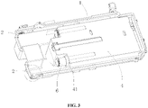
FIG. 3 is a structural schematic of a storage container and a guiding tube of a laundry processing agent feeding device according to the present invention; -
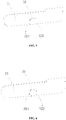
FIG. 4 is a partial enlarged view ofFIG. 3 ; -
FIG. 5 is a structural schematic of a second locking structure according to one preferred embodiment of the present invention; and -
FIG. 6 is a structural schematic of a second locking structure according to another preferred embodiment of the present invention. - Firstly, it should be appreciated by those skilled in the art that the embodiments described below are only for illustrating the technical principles of the present invention, and are not intended to limit the scope of the present invention. For example, although the following embodiments are illustrated in conjunction with a washing machine, this is not intended to be limiting and the technical scheme of the present invention is also applicable to other laundry processing apparatuses, such as an air wash apparatus, a shoe washing machine, and a combo washer/dryer machine. Such modification made to the object of application does not depart from the principles and scope of the present invention.
- It should be noted that in the description of the present invention, the terms "left", "right", "inner", "outer", etc., indicating directions or positional relationships are based on the directions or positional relationships shown in the drawings, which are only for convenience of description, and do not indicate or imply that the device or element must have a specific orientation or be configured and operated in a specific orientation, and thus should not be construed as limitation to the present invention. Furthermore, the terms "first" and "second" are used for descriptive purposes only and should not be construed as indicating or implying the relative importance.
- Furthermore, it should be noted that, in the description of the present invention, unless otherwise explicitly specified or limited, the terms "provide", "dispose", "connect" and "communicate" are to be construed broadly and, for example, may be a fixed connection, a detachable connection, or an integral connection; may be a mechanical or electrical connection; or may be a direct connection or an indirect connection through a medium, or may be an intercommunication between two elements. For those skilled in the art, the specific meanings of the aforementioned terms in the present invention can be understood according to specific conditions.
- For the falling-off risks of laundry processing agent feeding device of existing washing machines, as described in BACKGROUND, the present invention provides a washing machine intended to prevent the laundry processing agent feeding device from falling off from the washing machine.
- Specifically, as shown in
FIG. 1 , the washing machine disclosed herein comprises a locking device, a receivingmember 1 and a laundry processing agent feeding device provided in the receivingmember 1, wherein the laundry processing agent feeding device is slidably connected to the receivingmember 1, the locking device is provided between the receivingmember 1 and the laundry processing agent feeding device, and the locking device is configured for preventing the laundry processing agent feeding device from being disengaged from the receivingmember 1 in a locked state and is further configured for allowing the laundry processing agent feeding device to be disengaged from the receivingmember 1 in an unlocked state. The locking device has two states: a locked state and an unlocked state. In normal use, the locking device is in the locked state and can prevent the laundry processing agent feeding device from being disengaged from the receivingmember 1, eliminating potential safety risks; when the laundry processing agent feeding device requires cleaning or maintenance, the locking device turns to the unlocked state from the locked state, such that the laundry processing agent feeding device can be taken out of the receivingmember 1 for operations such as cleaning or maintenance. The receivingmember 1 is a receiving box, and the laundry processing agent feeding device is provided in the receiving box and is slidably connected to the receiving box. Certainly, the receivingmember 1 can be configured as a receiving barrel, a receiving tank, etc. Such adjustments and modifications can be made to the specific configuration of the receivingmember 1 without departing from the principles and scope of the present invention, and shall fall within the protection scope of the present invention. - It should be noted that, the laundry processing agent may be a detergent, and the laundry processing agent feeding device is a device for feeding the detergent; or the laundry processing agent may also be a care agent, and the laundry processing agent feeding device is a device for feeding the care agent. Such adjustments and modifications can be made to the specific types and kinds of the laundry processing agent without departing from the principles and scope of the present invention, and shall fall within the protection scope of the present invention.
- Preferably, as shown in
FIGs. 2 to 4 , the locking device comprises afirst locking structure 2 provided at a bottom or a side portion of the receivingmember 1 and asecond locking structure 3 correspondingly provided at a bottom or a side portion of the laundry processing agent feeding device; in the locked state, thefirst locking structure 2 and thesecond locking structure 3 cooperate to prevent the laundry processing agent feeding device from being disengaged from thereceiving member 1, and in the unlocked state, thefirst locking structure 2 and thesecond locking structure 3 separate from each other to allow the laundry processing agent feeding device to be disengaged from the receivingmember 1. Thefirst locking structure 2 may be provided at the bottom of thereceiving member 1, and thesecond locking structure 3 may be correspondingly provided at the bottom of the laundry processing agent feeding device; or alternatively, thefirst locking structure 2 may be provided at the side portion of thereceiving member 1, and thesecond locking structure 3 may be correspondingly provided at the side portion of the laundry processing agent feeding device. - Preferably, the
first locking structure 2 is abaffle 2, thesecond locking structure 3 comprises anelastic plate 31 and astopper 32 fixed to or integrated with theelastic plate 31, thebaffle 2 is fixed to or integrated with an inner sidewall of the receivingmember 1, and theelastic plate 31 is fixed to or integrated with an outer sidewall of the laundry processing agent feeding device. In the locked state, thestopper 32 abuts against thebaffle 2 under the action of theelastic plate 31 to prevent the laundry processing agent feeding device from being disengaged from the receivingmember 1, and in the unlocked state, theelastic plate 31 drives thestopper 32 to move through elastic deformation and thus separates thestopper 32 and thebaffle 2, allowing the laundry processing agent feeding device to be disengaged from the receivingmember 1. Specifically, in normal use, the locking device is in the locked state. When the laundry processing agent feeding device is pulled out (leftwards as shown in the figures) by a user, the laundry processing agent feeding device slides to a protruding position (referring to a position where the laundry processing agent can be fed into the laundry processing agent feeding device), and thestopper 32 abuts against thebaffle 2 to stop the laundry processing agent feeding device from continuously sliding leftwards, thus preventing the laundry processing agent feeding device from being disengaged from the receivingmember 1. When theelastic plate 31 is pressed inwards by hand, theelastic plate 31 elastically deforms and drives thestopper 32 to move towards the laundry processing agent feeding device to separate thestopper 32 and thebaffle 2. At this time, the locking device turns to the unlocked state from the locked state, such that the laundry processing agent feeding device can be taken out of the receivingmember 1 for operations such as cleaning or maintenance. Furthermore, thefirst locking structure 2 may be configured as a rib, and correspondingly thesecond locking structure 3 is configured as anelastic plate 31 provided with a ledge; or alternatively, thefirst locking structure 2 may be configured as a stopper, and correspondingly thesecond locking structure 3 is configured as an L-shaped baffle. Those skilled in the art may flexibly adjust the specific configurations of thefirst locking structure 2 and thesecond locking structure 3 in practice, as long as thefirst locking structure 2 and thesecond locking structure 3 can cooperate in the locked state to prevent the laundry processing agent feeding device from being disengaged from the receivingmember 1, and separate from each other in the unlocked state to allow the laundry processing agent feeding device to be disengaged from the receivingmember 1. - Preferably, as shown in
FIGs. 5 and 6 , thestopper 32 is provided with a stoppingsurface 321 substantially perpendicular to theelastic plate 31, and in the locked state, the stoppingsurface 321 abuts against thebaffle 2 to prevent the laundry processing agent feeding device from being disengaged from the receivingmember 1. The stoppingsurface 321 is preferably perpendicular to theelastic plate 31, but certainly, may also be slightly inclined to the left or right, as long as the stoppingsurface 321 can abut against thebaffle 2 in the locked state to prevent the laundry processing agent feeding device from being disengaged from the receivingmember 1. More preferably, thestopper 32 is further provided with an arc-shaped or flat slidingsurface 322 obliquely disposed relative to theelastic plate 31, such that the laundry processing agent feeding device is smoothly inserted into the receivingmember 1 during assembly. In one preferred condition, thestopper 32 is a wedge having a shape of a right triangle (for example, thestopper 32 inFIG. 5 ), a surface where one of the legs of the right triangle is located constitutes the stoppingsurface 321, and a surface where the hypotenuse of the right triangle is located constitutes the slidingsurface 322. In another preferred condition, thestopper 32 is a wedge having a shape of a right trapezoid (for example, thestopper 32 inFIG. 6 ), a surface where the perpendicular leg of the right trapezoid is located constitutes the stoppingsurface 321, and a surface where the oblique leg of the right trapezoid is located constitutes the slidingsurface 322. In the two preferred conditions above, the slidingsurface 322 and theelastic plate 31 enable a smooth transition, which is more favorable for smoothly inserting the laundry processing agent feeding device into the receivingmember 1. Certainly, thestopper 32 may be configured in other shapes, such as a conical shape and a pyramidal shape. Such adjustments and modifications can be made to the shape of thestopper 32 without departing from the principles and scope of the present invention, and shall fall within the protection scope of the present invention. - Preferably, as shown in
FIGs. 1 to 3 , the laundry processing agent feeding device comprises astorage container 4, a feedingcontainer 5 and a guidingtube 6, thestorage container 4 is fixed in the receivingmember 1, the feedingcontainer 5 is slidably connected to the receivingmember 1, one end of the guidingtube 6 communicates with the feedingcontainer 5, the other end of the guidingtube 6 is inserted into thestorage container 4, and the length of the guidingtube 6 is configured such that the other end of the guidingtube 6 is not disengaged from thestorage container 4 when the feedingcontainer 5 moves away from thestorage container 4. The laundry processing agent feeding device is configured as a split structure, where thestorage container 4 and the feedingcontainer 5 are separably arranged, and only the feedingcontainer 5 is slidably connected to the receivingmember 1, such that when adding the laundry processing agent, the user only needs to pull out the feedingcontainer 5 but not thestorage container 4. The feedingcontainer 5 communicates with thestorage container 4 via the guidingtube 6, and a right end of the guidingtube 6 is inserted into thestorage container 4. When the feedingcontainer 5 is pulled out (the feedingcontainer 5 moves leftwards in the figures), the guidingtube 6 moves along with the feedingcontainer 5, but the right end of the guidingtube 6 is not disengaged from thestorage container 4, such that the laundry processing agent fed into the feedingcontainer 5 can be delivered into thestorage container 4 through the guidingtube 6. After adding the laundry processing agent, the user pushes the feedingcontainer 5 and the guidingtube 6 back into the receivingmember 1, and a right portion of the guidingtube 6 is inserted into thestorage container 4 again. In this case, theelastic plate 31 is fixed to or integrated with an outer sidewall of the feedingcontainer 5. When the feedingcontainer 5 slides to a protruding position, thestopper 32 abuts against thebaffle 2 to prevent thefeeding container 5 from being disengaged from the receivingmember 1. When theelastic plate 31 is pressed inwards by hand, theelastic plate 31 elastically deforms and drives thestopper 32 to move towards the feedingcontainer 5 to separate thestopper 32 and thebaffle 2. At this time, the feedingcontainer 5 can be taken out of the receivingmember 1. - Furthermore, it should be noted that, as shown in
FIGs. 2 and3 , the feedingcontainer 5 is provided with two feedingcavities 51, of which one is a detergent feeding cavity and the other is a care agent feeding cavity. Correspondingly, thestorage container 4 is provided with two storage cavities: a detergent storage cavity communicated with the detergent feeding cavity through a guidingtube 6, and a care agent storage cavity communicated with the care agent feeding cavity through another guidingtube 6. Certainly, the number of thefeeding cavities 51 is not limited to two as described above. For example, the number of thefeeding cavities 51 can be one or three. Such adjustments and modifications can be made to the number of thefeeding cavities 51 without departing from the principles and scope of the present invention, and shall fall within the protection scope of the present invention. - Furthermore, it should be noted that the laundry processing agent feeding device may also be configured as an integral structure, where the
storage container 4 is fixed to or integrated with the feedingcontainer 5. In this case, the guidingtube 6 can be eliminated. - Preferably, as shown in
FIG. 3 , thestorage container 4 is provided with a directingstructure 41, and the other end of the guidingtube 6 is inserted into thestorage container 4 through the directingstructure 41. The directingstructure 41 is a directing joint 41 formed on an outer wall of thestorage container 4. The right end of the guidingtube 6 is inserted into thestorage container 4 through the directing joint 41. The directing joint 41 directs the guidingtube 6 when the guidingtube 6 moves along with the feedingcontainer 5. Certainly, the directingstructure 41 can be configured as other structures such as directing ribs or directing tubes. Such adjustments and modifications can be made to the specific configuration of the directingstructure 41 without departing from the principles and scope of the present invention, and shall fall within the protection scope of the present invention. - So far, the technical schemes of the present invention have been described in conjunction with the preferred embodiments shown in the drawings. However, it is apparent to those skilled in the art that the scope of the present invention is not limited to such specific embodiments. Equivalent modifications or substitutions to associated technical features can be made by those skilled in the art without departing from the principles of the present invention, and such modified or substituted technical schemes shall fall within the protection scope of the present invention.
Claims (10)
- A laundry processing apparatus, comprising: a locking device, a receiving member and a laundry processing agent feeding device provided in the receiving member, wherein the laundry processing agent feeding device is slidably connected to the receiving member, the locking device is provided between the receiving member and the laundry processing agent feeding device, and the locking device is configured for preventing the laundry processing agent feeding device from being disengaged from the receiving member in a locked state and is further configured for allowing the laundry processing agent feeding device to be disengaged from the receiving member in an unlocked state.
- The laundry processing apparatus according to claim 1, wherein the locking device comprises a first locking structure provided at a bottom or a side portion of the receiving member and a second locking structure correspondingly provided at a bottom or a side portion of the laundry processing agent feeding device; in the locked state, the first and second locking structures cooperate to prevent the laundry processing agent feeding device from coming out of the receiving member, and in the unlocked state, the first and second locking structures separate from each other to allow the laundry processing agent feeding device to be disengaged from the receiving member.
- The laundry processing apparatus according to claim 2, wherein the first locking structure is a baffle, the second locking structure comprises an elastic plate and a stopper fixed to or integrated with the elastic plate, the baffle is fixed to or integrated with an inner sidewall of the receiving member, and the elastic plate is fixed to or integrated with an outer sidewall of the laundry processing agent feeding device; in the locked state, the stopper abuts against the baffle under the action of the elastic plate to prevent the laundry processing agent feeding device from being disengaged from the receiving member, and in the unlocked state, the elastic plate drives the stopper to move through elastic deformation and thus separates the stopper and the baffle, allowing the laundry processing agent feeding device to be disengaged from the receiving member.
- The laundry processing apparatus according to claim 3, wherein the stopper is provided with a stopping surface substantially perpendicular to the elastic plate, and in the locked state, the stopping surface abuts against the baffle to prevent the laundry processing agent feeding device from being disengaged from the receiving member.
- The laundry processing apparatus according to claim 4, wherein the stopper is further provided with an arc-shaped or flat sliding surface obliquely disposed relative to the elastic plate, such that the laundry processing agent feeding device is smoothly inserted into the receiving member during assembly.
- The laundry processing apparatus according to claim 5, wherein the stopper is a wedge having a shape of a right triangle or a right trapezoid, a surface where one of the legs of the right triangle or the perpendicular leg of the right trapezoid is located constitutes the stopping surface, and a surface where the hypotenuse of the right triangle or the oblique leg of the right trapezoid is located constitutes the sliding surface.
- The laundry processing apparatus according to claim 1, wherein the laundry processing agent feeding device comprises a storage container, a feeding container and a guiding tube, the storage container is fixed in the receiving member, the feeding container is slidably connected to the receiving member, one end of the guiding tube communicates with the feeding container, the other end of the guiding tube is inserted into the storage container, and the length of the guiding tube is configured such that the guiding tube is not disengaged from the storage container when the feeding container moves away from the storage container.
- The laundry processing apparatus according to claim 7, wherein the storage container is provided with a directing structure, and the other end of the guiding tube is inserted into the storage container through the directing structure.
- The laundry processing apparatus according to claim 8, wherein the directing structure is a directing joint formed on an outer wall of the storage container.
- The laundry processing apparatus according to any one of claims 1 to 9, wherein the laundry processing apparatus is a washing machine, and/or the laundry processing agent feeding device is a device for feeding a detergent or a care agent, and/or the receiving member is a receiving box.
Applications Claiming Priority (2)
| Application Number | Priority Date | Filing Date | Title |
|---|---|---|---|
| CN201910556617.4A CN112127118A (en) | 2019-06-25 | 2019-06-25 | laundry treatment equipment |
| PCT/CN2020/095736 WO2020259313A1 (en) | 2019-06-25 | 2020-06-12 | Laundry treatment apparatus |
Publications (4)
| Publication Number | Publication Date |
|---|---|
| EP3992347A1 true EP3992347A1 (en) | 2022-05-04 |
| EP3992347A4 EP3992347A4 (en) | 2022-09-14 |
| EP3992347B1 EP3992347B1 (en) | 2026-02-25 |
| EP3992347C0 EP3992347C0 (en) | 2026-02-25 |
Family
ID=73850150
Family Applications (1)
| Application Number | Title | Priority Date | Filing Date |
|---|---|---|---|
| EP20831324.7A Active EP3992347B1 (en) | 2019-06-25 | 2020-06-12 | Laundry treatment apparatus |
Country Status (3)
| Country | Link |
|---|---|
| EP (1) | EP3992347B1 (en) |
| CN (1) | CN112127118A (en) |
| WO (1) | WO2020259313A1 (en) |
Families Citing this family (2)
| Publication number | Priority date | Publication date | Assignee | Title |
|---|---|---|---|---|
| CN115679645B (en) * | 2021-07-30 | 2026-05-01 | 合肥海尔洗衣机有限公司 | Washing machine water box assembly and washing machine |
| CN116791341B (en) * | 2022-03-15 | 2025-11-25 | 青岛海尔洗衣机有限公司 | A clothes dryer |
Family Cites Families (13)
| Publication number | Priority date | Publication date | Assignee | Title |
|---|---|---|---|---|
| EP2251480B1 (en) * | 2009-05-11 | 2017-11-29 | Electrolux Home Products Corporation N.V. | Laundry washing appliance |
| DE102010061097A1 (en) * | 2009-12-08 | 2011-06-09 | Vestel Beyaz Esya Sanayi Ve Ticaret A.S. | Washing machine, has attachment at cleaning agent drawer, stop projection penetrating into recess and another attachment passing below projection when head of drawer is lifted and latter attachment lies at projection |
| KR101748773B1 (en) * | 2011-01-04 | 2017-06-20 | 삼성전자주식회사 | Washing machine |
| CN108221286A (en) * | 2016-12-14 | 2018-06-29 | 青岛海尔滚筒洗衣机有限公司 | A kind of box component for washing agent and washing machine |
| CN106637835B (en) * | 2017-02-20 | 2019-08-23 | 无锡小天鹅电器有限公司 | Delivery device for washing machine and the washing machine with it |
| JP7061844B2 (en) * | 2017-04-05 | 2022-05-02 | 東芝ライフスタイル株式会社 | Washing machine |
| CN107044035B (en) * | 2017-05-31 | 2021-03-30 | 青岛海尔洗涤电器有限公司 | A washing machine water storage tank and washing machine |
| CN107354679B (en) * | 2017-08-21 | 2019-12-17 | 无锡小天鹅电器有限公司 | Distributor box assembly, detergent feeding device and washing machine |
| CN107916538A (en) * | 2017-11-24 | 2018-04-17 | 青岛海尔洗衣机有限公司 | A kind of box component for washing agent and washing machine |
| CN107974807A (en) * | 2017-12-11 | 2018-05-01 | 青岛海尔洗衣机有限公司 | Laundry treatment agents for clothes treatment device launch component and clothes treatment device |
| CN208701370U (en) * | 2018-03-27 | 2019-04-05 | 青岛海高设计制造有限公司 | A washing machine cleaning agent dispensing component and washing machine |
| CN208266485U (en) * | 2018-04-20 | 2018-12-21 | 青岛海尔滚筒洗衣机有限公司 | Laundry treatment agents for clothes treatment device launch component and clothes treatment device |
| CN208266487U (en) * | 2018-04-20 | 2018-12-21 | 青岛海尔滚筒洗衣机有限公司 | Laundry treatment agents for clothes treatment device launch component and clothes treatment device |
-
2019
- 2019-06-25 CN CN201910556617.4A patent/CN112127118A/en active Pending
-
2020
- 2020-06-12 WO PCT/CN2020/095736 patent/WO2020259313A1/en not_active Ceased
- 2020-06-12 EP EP20831324.7A patent/EP3992347B1/en active Active
Also Published As
| Publication number | Publication date |
|---|---|
| EP3992347B1 (en) | 2026-02-25 |
| EP3992347A4 (en) | 2022-09-14 |
| EP3992347C0 (en) | 2026-02-25 |
| CN112127118A (en) | 2020-12-25 |
| WO2020259313A1 (en) | 2020-12-30 |
Similar Documents
| Publication | Publication Date | Title |
|---|---|---|
| EP3992347B1 (en) | Laundry treatment apparatus | |
| CN108396506B (en) | Clothes treating device | |
| EP2471991B1 (en) | Washing machine | |
| EP2218387A1 (en) | Retainer for mop | |
| WO2016119833A1 (en) | Laundry machine front door opening mechanism involving rigid installation of a handle | |
| CN103261507B (en) | clothes dryer | |
| KR20080081626A (en) | Mop and detachment device and cleaner having same | |
| EP2876198B1 (en) | Washing machine with drawer assembly | |
| KR102889149B1 (en) | Washing machine and control method thereof | |
| EP3363944A1 (en) | Washing machine | |
| JP7273060B2 (en) | Clothing treatment agent input member for clothing treatment equipment and clothing treatment equipment | |
| CN111286932B (en) | Laundry treatment agent dispensing device for clothes treatment equipment and clothes treatment equipment | |
| CN112127119B (en) | A clothing processing agent input subassembly and clothing processing apparatus for clothing processing apparatus | |
| US20170233932A1 (en) | Liquid additive supply device for washing machine | |
| CN107254761B (en) | Tub assembly and laundry treating device having the same | |
| CN104259889B (en) | A kind of guide rail clamping device | |
| CN112127115B (en) | A clothing processing agent input subassembly and clothing processing apparatus for clothing processing apparatus | |
| CN223837769U (en) | Washing powder box structure with damping push-pull effect | |
| CN210657664U (en) | Woolen sweater ironing device | |
| JP6226602B2 (en) | Dishwasher | |
| EP2873765A1 (en) | Link lever that assists operation of a clutch assembly | |
| CN112127114B (en) | Clothes treating agent feeding assembly for clothes treating equipment and clothes treating equipment | |
| JP2021530257A (en) | Clothes processing agent input material for garment processing equipment and garment processing equipment | |
| WO2018108074A1 (en) | Detergent box assembly and washing machine | |
| CN219886383U (en) | Stirring device and clothes treatment equipment |
Legal Events
| Date | Code | Title | Description |
|---|---|---|---|
| STAA | Information on the status of an ep patent application or granted ep patent |
Free format text: STATUS: THE INTERNATIONAL PUBLICATION HAS BEEN MADE |
|
| PUAI | Public reference made under article 153(3) epc to a published international application that has entered the european phase |
Free format text: ORIGINAL CODE: 0009012 |
|
| STAA | Information on the status of an ep patent application or granted ep patent |
Free format text: STATUS: REQUEST FOR EXAMINATION WAS MADE |
|
| 17P | Request for examination filed |
Effective date: 20220123 |
|
| AK | Designated contracting states |
Kind code of ref document: A1 Designated state(s): AL AT BE BG CH CY CZ DE DK EE ES FI FR GB GR HR HU IE IS IT LI LT LU LV MC MK MT NL NO PL PT RO RS SE SI SK SM TR |
|
| A4 | Supplementary search report drawn up and despatched |
Effective date: 20220818 |
|
| RIC1 | Information provided on ipc code assigned before grant |
Ipc: D06F 39/02 20060101AFI20220811BHEP |
|
| DAV | Request for validation of the european patent (deleted) | ||
| DAX | Request for extension of the european patent (deleted) | ||
| STAA | Information on the status of an ep patent application or granted ep patent |
Free format text: STATUS: EXAMINATION IS IN PROGRESS |
|
| 17Q | First examination report despatched |
Effective date: 20240216 |
|
| GRAP | Despatch of communication of intention to grant a patent |
Free format text: ORIGINAL CODE: EPIDOSNIGR1 |
|
| STAA | Information on the status of an ep patent application or granted ep patent |
Free format text: STATUS: GRANT OF PATENT IS INTENDED |
|
| INTG | Intention to grant announced |
Effective date: 20251001 |
|
| GRAS | Grant fee paid |
Free format text: ORIGINAL CODE: EPIDOSNIGR3 |
|
| GRAA | (expected) grant |
Free format text: ORIGINAL CODE: 0009210 |
|
| STAA | Information on the status of an ep patent application or granted ep patent |
Free format text: STATUS: THE PATENT HAS BEEN GRANTED |
|
| AK | Designated contracting states |
Kind code of ref document: B1 Designated state(s): AL AT BE BG CH CY CZ DE DK EE ES FI FR GB GR HR HU IE IS IT LI LT LU LV MC MK MT NL NO PL PT RO RS SE SI SK SM TR |
|
| REG | Reference to a national code |
Ref country code: CH Ref legal event code: F10 Free format text: ST27 STATUS EVENT CODE: U-0-0-F10-F00 (AS PROVIDED BY THE NATIONAL OFFICE) Effective date: 20260225 Ref country code: GB Ref legal event code: FG4D |
|
| REG | Reference to a national code |
Ref country code: DE Ref legal event code: R096 Ref document number: 602020067627 Country of ref document: DE |
|
| REG | Reference to a national code |
Ref country code: IE Ref legal event code: FG4D |
|
| U01 | Request for unitary effect filed |
Effective date: 20260305 |
|
| U07 | Unitary effect registered |
Designated state(s): AT BE BG DE DK EE FI FR IT LT LU LV MT NL PT RO SE SI Effective date: 20260311 |
|
| PG25 | Lapsed in a contracting state [announced via postgrant information from national office to epo] |
Ref country code: RS Free format text: LAPSE BECAUSE OF FAILURE TO SUBMIT A TRANSLATION OF THE DESCRIPTION OR TO PAY THE FEE WITHIN THE PRESCRIBED TIME-LIMIT Effective date: 20260525 |
|
| PG25 | Lapsed in a contracting state [announced via postgrant information from national office to epo] |
Ref country code: ES Free format text: LAPSE BECAUSE OF FAILURE TO SUBMIT A TRANSLATION OF THE DESCRIPTION OR TO PAY THE FEE WITHIN THE PRESCRIBED TIME-LIMIT Effective date: 20260225 |
|
| PG25 | Lapsed in a contracting state [announced via postgrant information from national office to epo] |
Ref country code: PL Free format text: LAPSE BECAUSE OF FAILURE TO SUBMIT A TRANSLATION OF THE DESCRIPTION OR TO PAY THE FEE WITHIN THE PRESCRIBED TIME-LIMIT Effective date: 20260225 |
|
| PG25 | Lapsed in a contracting state [announced via postgrant information from national office to epo] |
Ref country code: GR Free format text: LAPSE BECAUSE OF FAILURE TO SUBMIT A TRANSLATION OF THE DESCRIPTION OR TO PAY THE FEE WITHIN THE PRESCRIBED TIME-LIMIT Effective date: 20260526 |
|
| PG25 | Lapsed in a contracting state [announced via postgrant information from national office to epo] |
Ref country code: NO Free format text: LAPSE BECAUSE OF FAILURE TO SUBMIT A TRANSLATION OF THE DESCRIPTION OR TO PAY THE FEE WITHIN THE PRESCRIBED TIME-LIMIT Effective date: 20260525 |
|
| PG25 | Lapsed in a contracting state [announced via postgrant information from national office to epo] |
Ref country code: HR Free format text: LAPSE BECAUSE OF FAILURE TO SUBMIT A TRANSLATION OF THE DESCRIPTION OR TO PAY THE FEE WITHIN THE PRESCRIBED TIME-LIMIT Effective date: 20260225 |
|
| PG25 | Lapsed in a contracting state [announced via postgrant information from national office to epo] |
Ref country code: IS Free format text: LAPSE BECAUSE OF FAILURE TO SUBMIT A TRANSLATION OF THE DESCRIPTION OR TO PAY THE FEE WITHIN THE PRESCRIBED TIME-LIMIT Effective date: 20260625 |
|
| U20 | Renewal fee for the european patent with unitary effect paid |
Year of fee payment: 7 Effective date: 20260629 |