EP3992089A1 - Vehicle arresting system - Google Patents
Vehicle arresting system Download PDFInfo
- Publication number
- EP3992089A1 EP3992089A1 EP20204720.5A EP20204720A EP3992089A1 EP 3992089 A1 EP3992089 A1 EP 3992089A1 EP 20204720 A EP20204720 A EP 20204720A EP 3992089 A1 EP3992089 A1 EP 3992089A1
- Authority
- EP
- European Patent Office
- Prior art keywords
- sublayer
- arresting system
- vehicle arresting
- layer
- base layer
- Prior art date
- Legal status (The legal status is an assumption and is not a legal conclusion. Google has not performed a legal analysis and makes no representation as to the accuracy of the status listed.)
- Withdrawn
Links
- 239000000463 material Substances 0.000 claims abstract description 66
- 239000000203 mixture Substances 0.000 claims description 49
- 229920002635 polyurethane Polymers 0.000 claims description 43
- 239000004814 polyurethane Substances 0.000 claims description 43
- 229920005862 polyol Polymers 0.000 claims description 39
- 150000003077 polyols Chemical class 0.000 claims description 39
- 239000012948 isocyanate Substances 0.000 claims description 37
- 150000002513 isocyanates Chemical class 0.000 claims description 34
- 229920002396 Polyurea Polymers 0.000 claims description 33
- 229920000768 polyamine Polymers 0.000 claims description 28
- 239000011381 foam concrete Substances 0.000 claims description 19
- 239000011230 binding agent Substances 0.000 claims description 16
- 239000006260 foam Substances 0.000 claims description 16
- 239000011494 foam glass Substances 0.000 claims description 16
- 239000010426 asphalt Substances 0.000 claims description 12
- 239000004744 fabric Substances 0.000 claims description 12
- 239000004570 mortar (masonry) Substances 0.000 claims description 11
- 239000004567 concrete Substances 0.000 claims description 10
- VYPSYNLAJGMNEJ-UHFFFAOYSA-N Silicium dioxide Chemical compound O=[Si]=O VYPSYNLAJGMNEJ-UHFFFAOYSA-N 0.000 claims description 7
- 239000000853 adhesive Substances 0.000 claims description 6
- 230000001070 adhesive effect Effects 0.000 claims description 6
- 229920005830 Polyurethane Foam Polymers 0.000 claims description 5
- 239000003822 epoxy resin Substances 0.000 claims description 5
- 229920000647 polyepoxide Polymers 0.000 claims description 5
- 229920000642 polymer Polymers 0.000 claims description 5
- 239000011496 polyurethane foam Substances 0.000 claims description 5
- 239000004746 geotextile Substances 0.000 claims description 4
- 238000004519 manufacturing process Methods 0.000 claims description 4
- 244000060011 Cocos nucifera Species 0.000 claims description 3
- 235000013162 Cocos nucifera Nutrition 0.000 claims description 3
- 240000000491 Corchorus aestuans Species 0.000 claims description 3
- 235000011777 Corchorus aestuans Nutrition 0.000 claims description 3
- 235000010862 Corchorus capsularis Nutrition 0.000 claims description 3
- 241001465754 Metazoa Species 0.000 claims description 3
- 241001494479 Pecora Species 0.000 claims description 3
- 239000000440 bentonite Substances 0.000 claims description 3
- 229910000278 bentonite Inorganic materials 0.000 claims description 3
- SVPXDRXYRYOSEX-UHFFFAOYSA-N bentoquatam Chemical compound O.O=[Si]=O.O=[Al]O[Al]=O SVPXDRXYRYOSEX-UHFFFAOYSA-N 0.000 claims description 3
- 239000000919 ceramic Substances 0.000 claims description 3
- 239000004927 clay Substances 0.000 claims description 3
- 229920001971 elastomer Polymers 0.000 claims description 3
- 239000011888 foil Substances 0.000 claims description 3
- 239000003365 glass fiber Substances 0.000 claims description 3
- 239000006262 metallic foam Substances 0.000 claims description 3
- 229930014626 natural product Natural products 0.000 claims description 3
- 239000000123 paper Substances 0.000 claims description 3
- 239000002985 plastic film Substances 0.000 claims description 3
- 229920006255 plastic film Polymers 0.000 claims description 3
- 229920000058 polyacrylate Polymers 0.000 claims description 3
- 229920000193 polymethacrylate Polymers 0.000 claims description 3
- 239000005060 rubber Substances 0.000 claims description 3
- 239000000377 silicon dioxide Substances 0.000 claims description 3
- 229920002994 synthetic fiber Polymers 0.000 claims description 3
- 239000004753 textile Substances 0.000 claims description 3
- 210000002268 wool Anatomy 0.000 claims description 3
- 239000003981 vehicle Substances 0.000 description 65
- 238000000034 method Methods 0.000 description 14
- 239000003054 catalyst Substances 0.000 description 10
- 239000003795 chemical substances by application Substances 0.000 description 10
- 239000003063 flame retardant Substances 0.000 description 8
- XLYOFNOQVPJJNP-UHFFFAOYSA-N water Substances O XLYOFNOQVPJJNP-UHFFFAOYSA-N 0.000 description 8
- -1 polyethylene Polymers 0.000 description 7
- 239000004094 surface-active agent Substances 0.000 description 5
- CURLTUGMZLYLDI-UHFFFAOYSA-N Carbon dioxide Chemical compound O=C=O CURLTUGMZLYLDI-UHFFFAOYSA-N 0.000 description 4
- 239000004568 cement Substances 0.000 description 4
- 230000007613 environmental effect Effects 0.000 description 3
- 238000009434 installation Methods 0.000 description 3
- 229920005906 polyester polyol Polymers 0.000 description 3
- PISLZQACAJMAIO-UHFFFAOYSA-N 2,4-diethyl-6-methylbenzene-1,3-diamine Chemical compound CCC1=CC(C)=C(N)C(CC)=C1N PISLZQACAJMAIO-UHFFFAOYSA-N 0.000 description 2
- KWYHDKDOAIKMQN-UHFFFAOYSA-N N,N,N',N'-tetramethylethylenediamine Chemical compound CN(C)CCN(C)C KWYHDKDOAIKMQN-UHFFFAOYSA-N 0.000 description 2
- 239000004721 Polyphenylene oxide Substances 0.000 description 2
- BLRPTPMANUNPDV-UHFFFAOYSA-N Silane Chemical group [SiH4] BLRPTPMANUNPDV-UHFFFAOYSA-N 0.000 description 2
- 239000007983 Tris buffer Substances 0.000 description 2
- 239000011358 absorbing material Substances 0.000 description 2
- 229910002092 carbon dioxide Inorganic materials 0.000 description 2
- 239000001569 carbon dioxide Substances 0.000 description 2
- ZBCBWPMODOFKDW-UHFFFAOYSA-N diethanolamine Chemical compound OCCNCCO ZBCBWPMODOFKDW-UHFFFAOYSA-N 0.000 description 2
- 229910021485 fumed silica Inorganic materials 0.000 description 2
- 229920000570 polyether Polymers 0.000 description 2
- 229920001228 polyisocyanate Polymers 0.000 description 2
- 239000005056 polyisocyanate Substances 0.000 description 2
- 229920001451 polypropylene glycol Polymers 0.000 description 2
- 229920001296 polysiloxane Polymers 0.000 description 2
- ZUFQCVZBBNZMKD-UHFFFAOYSA-M potassium 2-ethylhexanoate Chemical compound [K+].CCCCC(CC)C([O-])=O ZUFQCVZBBNZMKD-UHFFFAOYSA-M 0.000 description 2
- 229910000077 silane Inorganic materials 0.000 description 2
- KKEYFWRCBNTPAC-UHFFFAOYSA-L terephthalate(2-) Chemical compound [O-]C(=O)C1=CC=C(C([O-])=O)C=C1 KKEYFWRCBNTPAC-UHFFFAOYSA-L 0.000 description 2
- VGHSXKTVMPXHNG-UHFFFAOYSA-N 1,3-diisocyanatobenzene Chemical compound O=C=NC1=CC=CC(N=C=O)=C1 VGHSXKTVMPXHNG-UHFFFAOYSA-N 0.000 description 1
- ALQLPWJFHRMHIU-UHFFFAOYSA-N 1,4-diisocyanatobenzene Chemical compound O=C=NC1=CC=C(N=C=O)C=C1 ALQLPWJFHRMHIU-UHFFFAOYSA-N 0.000 description 1
- SIZPGZFVROGOIR-UHFFFAOYSA-N 1,4-diisocyanatonaphthalene Chemical compound C1=CC=C2C(N=C=O)=CC=C(N=C=O)C2=C1 SIZPGZFVROGOIR-UHFFFAOYSA-N 0.000 description 1
- ICLCCFKUSALICQ-UHFFFAOYSA-N 1-isocyanato-4-(4-isocyanato-3-methylphenyl)-2-methylbenzene Chemical compound C1=C(N=C=O)C(C)=CC(C=2C=C(C)C(N=C=O)=CC=2)=C1 ICLCCFKUSALICQ-UHFFFAOYSA-N 0.000 description 1
- DTZHXCBUWSTOPO-UHFFFAOYSA-N 1-isocyanato-4-[(4-isocyanato-3-methylphenyl)methyl]-2-methylbenzene Chemical compound C1=C(N=C=O)C(C)=CC(CC=2C=C(C)C(N=C=O)=CC=2)=C1 DTZHXCBUWSTOPO-UHFFFAOYSA-N 0.000 description 1
- QZWKEPYTBWZJJA-UHFFFAOYSA-N 3,3'-Dimethoxybenzidine-4,4'-diisocyanate Chemical compound C1=C(N=C=O)C(OC)=CC(C=2C=C(OC)C(N=C=O)=CC=2)=C1 QZWKEPYTBWZJJA-UHFFFAOYSA-N 0.000 description 1
- UPMLOUAZCHDJJD-UHFFFAOYSA-N 4,4'-Diphenylmethane Diisocyanate Chemical compound C1=CC(N=C=O)=CC=C1CC1=CC=C(N=C=O)C=C1 UPMLOUAZCHDJJD-UHFFFAOYSA-N 0.000 description 1
- 244000226021 Anacardium occidentale Species 0.000 description 1
- 239000005058 Isophorone diisocyanate Substances 0.000 description 1
- 235000019738 Limestone Nutrition 0.000 description 1
- OMRDSWJXRLDPBB-UHFFFAOYSA-N N=C=O.N=C=O.C1CCCCC1 Chemical compound N=C=O.N=C=O.C1CCCCC1 OMRDSWJXRLDPBB-UHFFFAOYSA-N 0.000 description 1
- 239000004677 Nylon Substances 0.000 description 1
- MXRIRQGCELJRSN-UHFFFAOYSA-N O.O.O.[Al] Chemical compound O.O.O.[Al] MXRIRQGCELJRSN-UHFFFAOYSA-N 0.000 description 1
- 229920000538 Poly[(phenyl isocyanate)-co-formaldehyde] Polymers 0.000 description 1
- 229920000608 Polyaspartic Polymers 0.000 description 1
- 239000004698 Polyethylene Substances 0.000 description 1
- 229910000831 Steel Inorganic materials 0.000 description 1
- WOURXYYHORRGQO-UHFFFAOYSA-N Tri(3-chloropropyl) phosphate Chemical compound ClCCCOP(=O)(OCCCCl)OCCCCl WOURXYYHORRGQO-UHFFFAOYSA-N 0.000 description 1
- KXBFLNPZHXDQLV-UHFFFAOYSA-N [cyclohexyl(diisocyanato)methyl]cyclohexane Chemical compound C1CCCCC1C(N=C=O)(N=C=O)C1CCCCC1 KXBFLNPZHXDQLV-UHFFFAOYSA-N 0.000 description 1
- 239000002253 acid Substances 0.000 description 1
- 125000001931 aliphatic group Chemical group 0.000 description 1
- 239000000956 alloy Substances 0.000 description 1
- 229910045601 alloy Inorganic materials 0.000 description 1
- 229910000410 antimony oxide Inorganic materials 0.000 description 1
- 230000001588 bifunctional effect Effects 0.000 description 1
- 230000015572 biosynthetic process Effects 0.000 description 1
- 229910021538 borax Inorganic materials 0.000 description 1
- 235000020226 cashew nut Nutrition 0.000 description 1
- 239000004359 castor oil Substances 0.000 description 1
- 235000019438 castor oil Nutrition 0.000 description 1
- 210000004027 cell Anatomy 0.000 description 1
- 230000001413 cellular effect Effects 0.000 description 1
- 210000003850 cellular structure Anatomy 0.000 description 1
- 239000002131 composite material Substances 0.000 description 1
- 235000014113 dietary fatty acids Nutrition 0.000 description 1
- KIQKWYUGPPFMBV-UHFFFAOYSA-N diisocyanatomethane Chemical compound O=C=NCN=C=O KIQKWYUGPPFMBV-UHFFFAOYSA-N 0.000 description 1
- 150000002148 esters Chemical class 0.000 description 1
- 239000000194 fatty acid Substances 0.000 description 1
- 229930195729 fatty acid Natural products 0.000 description 1
- 150000004665 fatty acids Chemical class 0.000 description 1
- 230000002349 favourable effect Effects 0.000 description 1
- 239000010881 fly ash Substances 0.000 description 1
- 230000008014 freezing Effects 0.000 description 1
- 238000007710 freezing Methods 0.000 description 1
- 239000011521 glass Substances 0.000 description 1
- ZEMPKEQAKRGZGQ-XOQCFJPHSA-N glycerol triricinoleate Natural products CCCCCC[C@@H](O)CC=CCCCCCCCC(=O)OC[C@@H](COC(=O)CCCCCCCC=CC[C@@H](O)CCCCCC)OC(=O)CCCCCCCC=CC[C@H](O)CCCCCC ZEMPKEQAKRGZGQ-XOQCFJPHSA-N 0.000 description 1
- 239000010440 gypsum Substances 0.000 description 1
- 229910052602 gypsum Inorganic materials 0.000 description 1
- 150000004677 hydrates Chemical class 0.000 description 1
- 125000002887 hydroxy group Chemical group [H]O* 0.000 description 1
- 239000005286 inorganic non-metallic glass Substances 0.000 description 1
- NIMLQBUJDJZYEJ-UHFFFAOYSA-N isophorone diisocyanate Chemical compound CC1(C)CC(N=C=O)CC(C)(CN=C=O)C1 NIMLQBUJDJZYEJ-UHFFFAOYSA-N 0.000 description 1
- 239000006028 limestone Substances 0.000 description 1
- 229910052751 metal Inorganic materials 0.000 description 1
- 239000002184 metal Substances 0.000 description 1
- 239000000178 monomer Substances 0.000 description 1
- 239000010466 nut oil Substances 0.000 description 1
- 229920001778 nylon Polymers 0.000 description 1
- VTRUBDSFZJNXHI-UHFFFAOYSA-N oxoantimony Chemical compound [Sb]=O VTRUBDSFZJNXHI-UHFFFAOYSA-N 0.000 description 1
- 229920003023 plastic Polymers 0.000 description 1
- 239000004033 plastic Substances 0.000 description 1
- 229920000162 poly(ureaurethane) Polymers 0.000 description 1
- 229920000573 polyethylene Polymers 0.000 description 1
- 230000001681 protective effect Effects 0.000 description 1
- 238000005086 pumping Methods 0.000 description 1
- 230000002787 reinforcement Effects 0.000 description 1
- 239000004576 sand Substances 0.000 description 1
- 235000010339 sodium tetraborate Nutrition 0.000 description 1
- 239000007921 spray Substances 0.000 description 1
- 239000010959 steel Substances 0.000 description 1
- 230000036561 sun exposure Effects 0.000 description 1
- 229920001169 thermoplastic Polymers 0.000 description 1
- DVKJHBMWWAPEIU-UHFFFAOYSA-N toluene 2,4-diisocyanate Chemical compound CC1=CC=C(N=C=O)C=C1N=C=O DVKJHBMWWAPEIU-UHFFFAOYSA-N 0.000 description 1
- RUELTTOHQODFPA-UHFFFAOYSA-N toluene 2,6-diisocyanate Chemical compound CC1=C(N=C=O)C=CC=C1N=C=O RUELTTOHQODFPA-UHFFFAOYSA-N 0.000 description 1
- UFTFJSFQGQCHQW-UHFFFAOYSA-N triformin Chemical compound O=COCC(OC=O)COC=O UFTFJSFQGQCHQW-UHFFFAOYSA-N 0.000 description 1
- BSVBQGMMJUBVOD-UHFFFAOYSA-N trisodium borate Chemical compound [Na+].[Na+].[Na+].[O-]B([O-])[O-] BSVBQGMMJUBVOD-UHFFFAOYSA-N 0.000 description 1
- 239000008096 xylene Substances 0.000 description 1
Images


Classifications
-
- B—PERFORMING OPERATIONS; TRANSPORTING
- B64—AIRCRAFT; AVIATION; COSMONAUTICS
- B64F—GROUND OR AIRCRAFT-CARRIER-DECK INSTALLATIONS SPECIALLY ADAPTED FOR USE IN CONNECTION WITH AIRCRAFT; DESIGNING, MANUFACTURING, ASSEMBLING, CLEANING, MAINTAINING OR REPAIRING AIRCRAFT, NOT OTHERWISE PROVIDED FOR; HANDLING, TRANSPORTING, TESTING OR INSPECTING AIRCRAFT COMPONENTS, NOT OTHERWISE PROVIDED FOR
- B64F1/00—Ground or aircraft-carrier-deck installations
- B64F1/02—Arresting gear; Liquid barriers
- B64F1/025—Arresting gear; Liquid barriers using decelerating or arresting beds
-
- E—FIXED CONSTRUCTIONS
- E01—CONSTRUCTION OF ROADS, RAILWAYS, OR BRIDGES
- E01C—CONSTRUCTION OF, OR SURFACES FOR, ROADS, SPORTS GROUNDS, OR THE LIKE; MACHINES OR AUXILIARY TOOLS FOR CONSTRUCTION OR REPAIR
- E01C9/00—Special pavings; Pavings for special parts of roads or airfields
- E01C9/007—Vehicle decelerating or arresting surfacings or surface arrangements, e.g. arrester beds ; Escape roads, e.g. for steep descents, for sharp bends
-
- E—FIXED CONSTRUCTIONS
- E01—CONSTRUCTION OF ROADS, RAILWAYS, OR BRIDGES
- E01F—ADDITIONAL WORK, SUCH AS EQUIPPING ROADS OR THE CONSTRUCTION OF PLATFORMS, HELICOPTER LANDING STAGES, SIGNS, SNOW FENCES, OR THE LIKE
- E01F13/00—Arrangements for obstructing or restricting traffic, e.g. gates, barricades ; Preventing passage of vehicles of selected category or dimensions
- E01F13/12—Arrangements for obstructing or restricting traffic, e.g. gates, barricades ; Preventing passage of vehicles of selected category or dimensions for forcibly arresting or disabling vehicles, e.g. spiked mats
Definitions
- the present invention relates to the field of vehicle arresting systems and methods for producing such systems.
- Engineered material arrestor systems comprising high energy absorbing materials have been developed for arresting an aircraft when overshooting the runway. Those materials crush under the weight of a moving aircraft. By transferring kinetic energy from the aircraft to the material the aircraft is slowed down.
- Current systems typically use cellular cement materials or lightweight aggregate foams made from recycled glass.
- the present invention relates to a vehicle arresting system comprising:
- the base layer comprising at least one compressible material is used to slow down a moving vehicle.
- the compressible material is a high energy absorbing material characterized by a low bulk density, which crushes under the weight of a moving vehicle.
- the top layer provides a cover for the base layer in order to protect the base layer from external or environmental influences such as harsh weather conditions (e.g. water, ice, snow, UV light, wind) or jet blasts.
- harsh weather conditions e.g. water, ice, snow, UV light, wind
- jet blasts e.g. water, ice, snow, UV light, wind
- the top layer can be effectively linked to said base layer by using a carrier and a fixation means according to the present invention.
- the linkage between the base layer and the top layer is further improved by the levelling layer positioned above the carrier and below the top layer.
- the fixation means allows to firmly attach the carrier to the base layer. This is particularly advantageous, because it provides a structure which is highly resistant to jet blast uplift forces. Furthermore, without the carrier, the top layer cannot be durably adhered to the base layer due to the relatively weak binding properties of the base layer, which is a result of a low bulk density and low tensile strength of the base layer.
- the levelling layer is positioned on the carrier and/or embeds the carrier.
- the levelling layer further improves the binding of the top layer to the base layer and provides a smooth and flat surface.
- the base layer and the top layer may comprise several sublayers.
- the top layer has weather protective and fire retardant properties.
- Another aspect of the present invention relates to a method for producing a vehicle arresting system comprising a base layer, a carrier, at least one fixation means for fixing the carrier to the base layer, a levelling layer and a top layer.
- the vehicle arresting system 1 of the present invention is also referred to as "engineered materials arresting system” (EMAS) and can be used for decelerating or stopping a moving vehicle such as an aircraft, a cars and a truck.
- the system may be installed on roads, streets and airports.
- the system is used for arresting an aircraft overshooting the runway. Therefore the inventive system is preferably installed as an extension of airport runways.
- the system may be used to prevent vehicles such as cars or trucks from entering a protected area, for example a pedestrian area.
- the vehicle arresting system tolerates the weight of pedestrians and light vehicles such as bicycles, but crushes under the weight of heavier vehicles such as cars and trucks.
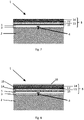
- Fig. 1 shows the cross section of a vehicle arresting system 1 according to the present invention, comprising a base layer 2, a carrier 3 fixed to the base layer by a fixation means 4, a levelling layer 5 and a top layer 6.
- the vehicle arresting system 1 comprises at least one means for releasing vapor pressure 7 from the base layer.
- An embodiment of the present invention comprising a means for releasing vapor pressure 7 is depicted in Fig. 2 .
- the means for releasing vapor pressure 7 may have the form of a tube reaching from the base layer to the surface.
- the means for releasing vapor pressure 7 may stand out from the surface of the top layer to allow humidity to escape from the base layer. This is particularly useful if the top layer is waterproof and air tight.
- a means for releasing vapor pressure 7 may be installed every 10 to 1000 m 2 on the vehicle arresting system 1, preferably every 250 to 500 m 2 .
- the base layer 2 comprises at least one compressible material.
- the compressible material may be selected from one or more of the group consisting of concrete, cellular concrete, foamed concrete, foam glass, ceramic foam, polymeric foam, bound expanded clay aggregate, silica foam, bound foam glass, metal foam, autoclaved aerated concrete and aggregates thereof.
- the concrete used according to the present invention may comprise cement, which is a common binder in concrete.
- the base layer 2 consists of foamed concrete or cellular concrete.
- the foamed concrete is produced from local concrete near the place of installation of the vehicle arresting system and is pumped directly to the place of use. Producing foamed concrete on site and pumping it directly to the place of installation allows using local resources and reduces the need for heavy machines for installing the EMAS, thereby reducing installation time and costs.
- the foamed concrete is preferably applied at a thickness of 30 mm to 1250 mm, preferably 40 mm to 1000 mm, more preferably 50 mm to 500 mm.
- the foamed concrete may be supplied in the form of blocks produced in a factory.
- the compressible material is in the form of an aggregate.
- the compressible material consists of or comprises foam glass aggregate, such as a loose or bagged foam glass aggregate forming a bed.
- the foam glass used in the system of the present invention may be fabricated from inorganic non-metallic glass material.
- the foam glass typically comprises cellular structures with a diameter ranging from 0.1 to 5 mm, preferably from 0.2 to 4 mm, more preferably from 0.5 to 3 mm, more preferably from 1 to 2 mm.
- the foam glass of the present invention may comprise open and/or closed cells. Methods for producing such foam glass are well known in the art.
- the base layer 2 comprises one or more sublayers.
- at least one sublayer comprises a compressible material as defined above.
- the base layer comprises a bottom sublayer 8, a middle sublayer 9 and optionally an upper sublayer 10.
- Fig. 3 shows an embodiment of the present invention, wherein the base layer 2 consists of a bottom sublayer 8, a middle sublayer 9 and an upper sublayer 10.
- the bottom sublayer 8 comprises a compressible material such as cellular concrete or foam glass aggregate.
- a means for releasing vapor pressure 7' may be installed on the bottom sublayer 8 to release humidity from the bottom sublayer 8.
- Fig. 4 shows an additional means for releasing vapor pressure 7'.
- the bottom sublayer 8 comprises a foam glass aggregate
- the middle sublayer 9 comprises a material selected from the group consisting of a controlled low-strength material, foamed concrete and mixtures thereof
- the optional upper sublayer 10 comprises polyacrylate or polymethacrylate.
- controlled low-strength material refers, for instance, to a low-strength concrete material.
- Such materials which may be a particular form of cementitious material, may have a compressive strength between about 1.38 and about 4.14 MPa, with a preferred density of about 1762 to 2082 kg/m 3 .
- CLSM may be made by mixing sand and cement with water optionally by adding further fly ash, admixtures, and/or fibres.
- the bottom sublayer 8 comprises at least one block of compressible material 11
- the middle sublayer 9 comprises a foam sheet
- the optional upper sublayer 10 comprises a polymer, wherein the block of compressible material is at least partly covered by a mesh 12.
- Fig. 5 shows an embodiment of the present invention, wherein the base layer 8 comprises a block of compressible material 11 covered by a mesh 12.
- the compressible material is cellular concrete.
- the foam sheet consists of polyethylene foam.
- the mesh 12 is preferably a nylon mesh.
- the upper layer may consist of a thermoplastic polymer.
- the bottom sublayer 8 comprises at least one block of compressible material 11 and an upper sublayer 10 comprising a polymer.
- the carrier 3 is selected from the group consisting of a grid, a net, a mesh, a foil, a fleece, a mat and mixtures thereof.
- the carrier 3 according to the present invention is strong enough to firmly attach the top layer 6 to the base layer 2 and weak enough to break under the weight of a moving vehicle.
- the carrier 3 comprises a material selected from the group consisting of a geotextile material, a geo-fleece, a rubber mat, a bentonite mat, a synthetic fabric, a glass fibre fabric, a textile cloth, a plastic film, a fabric of an animal product, preferably sheep's wool, a fabric of a natural product, preferably jute or coconut, a paper, a cardboard and any a combination thereof.
- a material selected from the group consisting of a geotextile material, a geo-fleece, a rubber mat, a bentonite mat, a synthetic fabric, a glass fibre fabric, a textile cloth, a plastic film, a fabric of an animal product, preferably sheep's wool, a fabric of a natural product, preferably jute or coconut, a paper, a cardboard and any a combination thereof.
- the carrier 3 is a grid, a net or a mesh made of a geotextile material.
- the carrier 3 is a net or a mesh with a mesh size ranging from 0 to 350 mm, preferably 10 to 50 mm.
- the carrier 3 preferably covers the upper surface of the base layer 2.
- the carrier 3 may additionally also cover the side surfaces of the base layer 2.
- the carrier 3 is fixed to the base layer 2 by at least one fixation means 4. Any fixation means 4 capable of firmly attaching the carrier to the base layer 2 is suitable.
- the carrier 3 may be fixed to the base layer 2 by a fixation means 4 on the upper surface or on the side surfaces of the base layer 2.
- the fixation means 4 is used to fix the carrier 3 to the base layer 2 at regular intervals.
- the skilled person is able to determine the necessary amount of fixation means 4 per m 2 of the vehicle arresting system 1. For example, if the fixation means 4 is an anchor, 0.1 to 8 anchors, preferably 1 to 5 anchors, may be used per m 2 of the vehicle arresting system 1.
- the fixation means 4 is selected from the group consisting of an impact anchor, an adhesive anchor, an expansion anchor, a rope anchor, a bearing plate, an anchor plate, a screw and an adhesive.
- the fixation means may be fabricated from a metal, an alloy, a polymer or a composite material.
- the fixation means is an anchor or a screw.
- the levelling layer 5 comprises or consists of a material selected from the group consisting of polyurethane, polyurea, bitumen, mortar, hydraulic binder, polyurethane foam, epoxy resin and any combination thereof.
- the levelling layer may also comprise a hydraulic binder in the form of an aggregate.
- the levelling layer may further comprise fibres for reinforcement, for example steel fibres and/or plastic fibres.
- hydraulic binder refers to a material which hydrates in the presence of water and thereby forms a paste which hardens over time.
- the hydraulic binder may for example be selected from the group consisting of cement, limestone and gypsum.
- the levelling layer 5 consists of bitumen and/or a hydraulic binder.
- the levelling layer 5 is obtainable from a first composition comprising at least one isocyanate and at least one polyamine and/or at least one polyol.
- the levelling layer 5 preferably comprises polyurea and/or polyurethane.
- the first composition used to produce the levelling layer 5 may further comprise a floating agent, such as pyrogenic silica.
- At least one isocyanate means that one or more different types of isocyanates, polyols and polyamines may be used.
- the first composition comprising at least one isocyanate and at least one polyamine and/or at least one polyol is applied on the carrier 3 by using a spray, a brush, a roller or any other appropriate application technique.
- the at least one isocyanate according to the present invention is preferably selected from the group consisting of aliphatic isocyanates such as methylene diisocyanate, a bifunctional monomer of tetra-alkyl xylene diisocyanate, cyclohexan diisocyanate, 1,12-dodecane diisocyanate, 1,4-tetramethylene diisocyanate, isophorone diisocyanate, and dicyclohexylmethane diisocyanate; aromatic isocyanates such as m-phenylene diisocyanate, p-phenylene diisocyanate, polymethylene polyphenylisocyanate, 2,4-toluene diisocyanate, 2,6-toluene diisocyanate, dianisidine diisocyanate, bitolylene diisocyanate, naphthalene-1,4-diisocyanate, and diphenylene-4,4'-di
- the polyamine of the first composition is selected from the group consisting of polyoxypropylenediamine, diethyltoluenediamine, methylenedianaline, polyoxypropylene triamine, substituted methylenedianaline and secondary methylenedianaline.
- the at least one polyol of the first composition is selected from the group consisting of polyester polyols, preferably polyetheylene terephthalate (PET) based polyols, more preferably recycled PET based polyols.
- PET polyetheylene terephthalate
- the polyol may also be selected from the group consisting of mannich based polyols, aliphatic amine based polyols and polyether-based polyols.
- the ratio of the least one isocyanate and the at least one polyamine and/or at least one polyol in the first composition used to produce the levelling layer 5 is from 3:1 to 7:1, preferably from 4:1 to 6:1, more preferably from 4.5:1 to 5.5:1.
- the levelling layer 5 comprises a mixture of at least one polyol and at least one polyamine.
- the ratio of the at least one polyol and the at least one polyamine may range from 2:1 to 6:1, preferably from 3:1 to 5:1, more preferably from 3.5:1 to 4.5:1.
- a mixture of polyols and polyamines in the levelling layer 5 allows obtaining good rheological properties and a smooth and flat surface.
- the levelling layer 5 may have a thickness of 0.1 to 10 mm, preferably from 0.5 to 5 mm, more preferably from 1 to 4 mm, more preferably from 1 to 3 mm.
- the top layer 6 preferably comprises at least one material selected from the group consisting of polyurea, polyurethane, bitumen, mortar, hydraulic binder and mixtures thereof.
- the top layer 6 comprises bitumen, mortar and/or a hydraulic binder.
- the top layer 6 comprises a fire retardant.
- the fire retardant renders the top layer 6 heat resistant.
- the fire retardant is preferably selected from the group consisting of tris(chloropropyl) phosphate, aluminium trihydrate, antimony oxide and sodium borate.
- the top layer 6 comprises one or more sublayers.
- the top layer 6 comprises a polyurethane sublayer 13 and a polyurea sublayer 14.
- the polyurethane sublayer 13 and polyurea sublayer 14 allow a high durability of the top layer 6 and provide protection against harsh weather conditions and jet blasts.
- Fig. 6 shows an embodiment of the present invention comprising a base layer 2, a carrier 3, a fixation means 4, a levelling layer 5 and a top layer 6 consisting of a polyurethane sublayer 13 and a polyurea sublayer 14.
- the base layer 2 may comprise a compressible material as described above.
- the base layer 2 may have any of the structures as described above.
- the base layer 2 may consist of one or more sublayers, such as a bottom sublayer 8, a middle sublayer 9 and an upper sublayer 10.
- the polyurethane sublayer 13 is positioned above said levelling layer 5 and below said polyurea sublayer 14.
- the polyurethane sublayer 13 is obtainable from at least one isocyanate and a second composition comprising at least polyol and at least one catalyst.
- the at least one isocyanate may be an isocyanate as defined above.
- the polyol of the second composition is preferably a polyester polyol, more preferably a polyetheylene terephthalate (PET) based polyol, even more preferably a recycled PET based polyol.
- PET polyetheylene terephthalate
- the polyol may also be selected from the group consisting of mannich based polyols, aliphatic amine based polyols and polyether-based polyols.
- the catalyst is preferably selected from the group consisting of 1,3,5-tris(dimethylaminopropyl)-1,3,5-hexahydrotriazine, N,N,N'-trimethyl-N'-hydroxyethyl-bisaminoethylether and potassium octoate.
- the at least one isocyanate and the second composition comprising at least one polyol and at least one catalyst are preferably combined to form the polyurethane sublayer 13 in a ratio of 0.1:1 to 5:1, preferably 0.5:1 to 4:1, more preferably 0.8:1 to 2.5:1, more preferably 0.9:1 to 1.1:1.
- said second composition comprises 60 to 95 wt%, preferably 70 to 90 wt%, of the at least one polyol, and 1 to 5 wt%, preferably 2 to 4 wt%, of the at least one catalyst.
- the second composition may further comprise water, preferably 1 to 5 wt% water, even more preferably 1.2 to 3 wt% of water. Water is added to generate carbon dioxide gas by a reaction of the isocyanate with water. Due to the formation of carbon dioxide, the polyurethane is formed as a foam.
- the second composition comprising a polyol and at least one catalyst further comprises a fire retardant as defined above and optionally a surfactant.
- the surfactant is a silicone surfactant.
- the polyurethane layer 13 has a thickness of 1 to 50 mm, preferably 1 to 40 mm, more preferably 1 to 30 mm, more preferably 1 to 20 mm, more preferably 1 to 15 mm, more preferably 5 to 10 mm.
- a thickness of the polyurethane sublayer 14 within this range is favorable for the crushing properties of the inventive vehicle arresting system.
- the polyurea sublayer 14 is obtainable from at least one isocyanate and a third composition comprising at least one polyamine.
- the at least one isocyanate may be an isocyanate as defined above.
- the polyamine of the third composition may be selected from the group consisting of polyoxypropylenediamine, diethyltoluenediamine, methylenedianaline, polyoxypropylene triamine, substituted methylenedianaline and secondary methylenedianaline.
- the at least one isocyanate and the third composition comprising at least one polyamine are preferably combined to form the polyurea sublayer 14 in a ratio of 0.5:1.5 to 1.5:0.5, preferably 1:1.
- the third composition comprising at least one polyamine comprises 60 to 100 wt%, preferably 65 to 95 wt%, more preferably 65 to 90 wt%, of the at least one polyamine.
- said third composition further comprises 2 to 20 wt%, preferably 5 to 15 wt%, more preferably 5 to 10 wt%, of a fire retardant as defined above.
- the polyurea sublayer 14 has a thickness of 0.1 to 10 mm, preferably 0.2 to 5 mm, more preferably 0.5 to 3 mm, more preferably 0.5 to 2 mm, more preferably 0.5 to 1.2 mm, more preferably 0.5 to 1 mm.
- the top layer 6 further comprises a primer sublayer 15 positioned between said levelling layer 5 and said polyurethane sublayer 13. Additionally the top layer 6 may comprise a primer sublayer 15' positioned between said polyurethane sublayer 13 and said polyurea sublayer 14. The primer sublayers 15 and 15' are used to seal the surface and to improve the binding of the levelling layer 5 to the polyurethane sublayer 13 and the binding of the polyurethane sublayer 13 to the polyurea sublayer 14.
- Fig. 7 shows the embodiment of Fig. 6 further comprising a primer sublayer 15 and 15'.
- the primer sublayer 15 and 15' comprises polyurethane, preferably obtainable by combining at least one polyisocyanate and at least one polyol.
- the primer sublayer 15 and 5' is substantially water-free.
- the at least one polyol used in the primer sublayer 15 and 15' may be a hydroxyl group comprising triglyceride or fatty acid from a natural source, preferably selected from the group consisting of castor oil, ricolinoeic acid, cashew nut oil and soy based polyol.
- the at least one isocyanate and the at least one polyol are combined to produce the primer sublayer 15 and 15' in a ratio of 0.5:1.5 to 1.5:0.5, preferably 1:1.
- the vehicle arresting system 1 further comprises an anti-slip layer 16 positioned above the top layer 6.
- the anti-slip layer 16 comprises polyurea and optionally an air release agent.
- the anti-slip layer 16 is obtainable from at least one isocyanate and a fourth composition comprising at least one polyamine.
- the at least one isocyanate may be an isocyanate as defined above.
- the at least one polyamine of the fourth composition may be selected from the group consisting of a polyaspartic ester, preferably based on methylene dicyclohexyl amines.
- the air release agent is preferably a silane based air release agent.
- the at least one isocyanate and the fourth composition comprising at least one polyamine are combined to produce the anti-slip layer 16 in a ratio of 0.5:2 to 2:0.5, preferably 1:1.5.
- the fourth composition comprises 80 wt% to 98 wt%, preferably 90 wt% to 98 wt%, more preferably 95 wt% to 98 wt%, of the at least one polyamine.
- the fourth composition may additionally comprise 2 wt% to 5 wt%, preferably 2 wt% to 4 wt%, of the at least one air release agent.
- the anti-slip layer 16 facilitates the movement of people or light vehicles on the vehicle arresting system 1. Furthermore, the anti-slip layer 16 may provide improved color stability of the system according to the present invention.
- the anti-slip layer 16 has a thickness of 0.1 to 2 mm, preferably 0.25 to 1 mm.
- Fig. 8 shows the embodiment of Fig. 7 , further comprising an anti-slip layer 16 on top of the top layer 6.
- the anti-slip layer 16 may be applied on any top layer material described herein.
- the present invention further relates to a method for producing a vehicle arresting system 1.
- the method comprises the steps of:
- a means for releasing vapor pressure 7 is positioned on said base layer 2.
- the levelling layer 5 is formed by applying a material selected from the group consisting of bitumen, mortar, hydraulic binder, polyurethane foam, an epoxy resin and any combination thereof.
- the levelling layer 5 is formed by applying a first composition comprising at least one isocyanate and at least one polyamine and/or at least one polyol as defined above.
- the top layer 6 is formed by applying at least one material selected from the group consisting of polyurethane, polyurea, bitumen, mortar, hydraulic binder and mixtures thereof.
- said top layer 6 comprises a polyurethane sublayer 13 and a polyurea sublayer 14 as defined above.
- the polyurethane sublayer 13 may be formed from at least one isocyanate and a second composition comprising a polyester polyol and at least one catalyst as defined above.
- the polyurea sublayer 14 may be formed by applying at least one isocyanate and a third composition comprising at least one polyamine as defined above.
- a primer sublayer 15 is applied on said levelling layer 5 and/or a primer sublayer 15' is applied on said polyurethane sublayer 13.
- the primer sublayer 15 and 15' may have a composition as defined above.
- an anti-slip layer 16 is formed on said top layer 6.
- the anti-slip layer 16 is preferably formed by applying at least one isocyanate and a fourth composition comprising at least one polyamine and optionally at least one air release agent.
Abstract
The present invention relates to a vehicle arresting system (1) comprising:
e) a base layer (2) comprising at least one compressible material;
f) a carrier (3) positioned and fixed by at least one fixation means (4) on said base layer (2);
g) a levelling layer (5) positioned on and/or embedding said carrier (3); and
h) a top layer (6).
e) a base layer (2) comprising at least one compressible material;
f) a carrier (3) positioned and fixed by at least one fixation means (4) on said base layer (2);
g) a levelling layer (5) positioned on and/or embedding said carrier (3); and
h) a top layer (6).
Description
- The present invention relates to the field of vehicle arresting systems and methods for producing such systems.
- An aircraft overshooting the runway due to high speed or unfavourable weather conditions may have serious consequences for people and aircrafts. Engineered material arrestor systems (EMAS) comprising high energy absorbing materials have been developed for arresting an aircraft when overshooting the runway. Those materials crush under the weight of a moving aircraft. By transferring kinetic energy from the aircraft to the material the aircraft is slowed down. Current systems typically use cellular cement materials or lightweight aggregate foams made from recycled glass.
- However, the durability of existing EMAS is limited. Variable and harsh weather conditions (e.g. sun exposure in summer and freezing temperatures in winter, rain, hail, storms etc.) negatively affect present aircraft arresting systems. In addition, jet blast from aircrafts taking off and light traffic are known to damage currently applied EMAS. In particular, the surface of the current systems does not show sufficient resistance in regard to such environmental and aircraft-caused conditions.
- It is an object of the present invention to provide a vehicle arresting system which overcomes the drawbacks of known EMAS and which can be produced quickly in an environmental friendly manner and with limited costs.
- The present invention relates to a vehicle arresting system comprising:
- a) a base layer comprising at least one compressible material;
- b) a carrier positioned and fixed by at least one fixation means on said base layer;
- c) a levelling layer positioned on and/or embedding said carrier; and
- d) a top layer.
- The base layer comprising at least one compressible material is used to slow down a moving vehicle. The compressible material is a high energy absorbing material characterized by a low bulk density, which crushes under the weight of a moving vehicle.
- The top layer provides a cover for the base layer in order to protect the base layer from external or environmental influences such as harsh weather conditions (e.g. water, ice, snow, UV light, wind) or jet blasts.
- It turned surprisingly out that the top layer can be effectively linked to said base layer by using a carrier and a fixation means according to the present invention. The linkage between the base layer and the top layer is further improved by the levelling layer positioned above the carrier and below the top layer.
- The fixation means allows to firmly attach the carrier to the base layer. This is particularly advantageous, because it provides a structure which is highly resistant to jet blast uplift forces. Furthermore, without the carrier, the top layer cannot be durably adhered to the base layer due to the relatively weak binding properties of the base layer, which is a result of a low bulk density and low tensile strength of the base layer.
- The levelling layer is positioned on the carrier and/or embeds the carrier. The levelling layer further improves the binding of the top layer to the base layer and provides a smooth and flat surface.
- According to the present invention, the base layer and the top layer may comprise several sublayers. Preferably, the top layer has weather protective and fire retardant properties.
- Another aspect of the present invention relates to a method for producing a vehicle arresting system comprising a base layer, a carrier, at least one fixation means for fixing the carrier to the base layer, a levelling layer and a top layer.
-
-
Fig. 1 shows the cross section of a vehicle arrestingsystem 1 according to the present invention. The system comprises abase layer 2. Acarrier 3 is positioned on thebase layer 2 and fixed to the base layer by a fixation means 4. Alevelling layer 5 covers and/or embeds the carrier. Thelevelling layer 5 is covered by atop layer 6. -
Fig. 2 shows a cross section of a vehicle arrestingsystem 1 as depicted inFig. 1 comprising an additional means for releasingvapour pressure 7 from thebase layer 2. -
Fig. 3 shows a cross section of a vehicle arrestingsystem 1 as depicted inFig. 1 , wherein thebase layer 2 consists of 3 sublayers: abottom sublayer 8, amiddle sublayer 9 and acover sublayer 10. -
Fig. 4 shows a cross section of a vehicle arrestingsystem 1 as depicted inFig. 3 , comprising an additional means for releasing vapour pressure 7' from thebottom sublayer 8. -
Fig. 5 shows a cross section of a vehicle arrestingsystem 1 as depicted inFig. 3 , wherein thebottom sublayer 8 comprises a block ofcompressible material 11 covered by amesh 12. -
Fig. 6 shows a cross section of a vehicle arrestingsystem 1 as depicted inFig. 1 , wherein thetop layer 6 comprises apolyurethane layer 13 and apolyurea layer 14, whichpolyurea layer 14 is positioned above thepolyurethane layer 13. -
Fig. 7 shows a cross section of a vehicle arrestingsystem 1 as depicted inFig. 6 , wherein aprimer sublayer 15 is positioned between thelevelling layer 5 and thepolyurethane sublayer 13 and a primer sublayer 15' is positioned between thepolyurethane sublayer 13 and thepolyurea sublayer 14. -
Fig. 8 shows a cross section of a vehicle arrestingsystem 1 as depicted inFig. 7 , wherein ananti-slip layer 16 is positioned above thetop layer 6. - The vehicle arresting
system 1 of the present invention is also referred to as "engineered materials arresting system" (EMAS) and can be used for decelerating or stopping a moving vehicle such as an aircraft, a cars and a truck. The system may be installed on roads, streets and airports. Preferably, the system is used for arresting an aircraft overshooting the runway. Therefore the inventive system is preferably installed as an extension of airport runways. - According to another aspect, the system may be used to prevent vehicles such as cars or trucks from entering a protected area, for example a pedestrian area. Preferably, the vehicle arresting system tolerates the weight of pedestrians and light vehicles such as bicycles, but crushes under the weight of heavier vehicles such as cars and trucks.
-
Fig. 1 shows the cross section of a vehicle arrestingsystem 1 according to the present invention, comprising abase layer 2, acarrier 3 fixed to the base layer by a fixation means 4, alevelling layer 5 and atop layer 6. - According to one embodiment, the
vehicle arresting system 1 comprises at least one means for releasingvapor pressure 7 from the base layer. An embodiment of the present invention comprising a means for releasingvapor pressure 7 is depicted inFig. 2 . - The means for releasing
vapor pressure 7 may have the form of a tube reaching from the base layer to the surface. The means for releasingvapor pressure 7 may stand out from the surface of the top layer to allow humidity to escape from the base layer. This is particularly useful if the top layer is waterproof and air tight. For example, a means for releasingvapor pressure 7 may be installed every 10 to 1000 m2 on thevehicle arresting system 1, preferably every 250 to 500 m2. - According to the present invention, the
base layer 2 comprises at least one compressible material. The compressible material may be selected from one or more of the group consisting of concrete, cellular concrete, foamed concrete, foam glass, ceramic foam, polymeric foam, bound expanded clay aggregate, silica foam, bound foam glass, metal foam, autoclaved aerated concrete and aggregates thereof. - The concrete used according to the present invention may comprise cement, which is a common binder in concrete.
- According to one embodiment, the
base layer 2 consists of foamed concrete or cellular concrete. Preferably, the foamed concrete is produced from local concrete near the place of installation of the vehicle arresting system and is pumped directly to the place of use. Producing foamed concrete on site and pumping it directly to the place of installation allows using local resources and reduces the need for heavy machines for installing the EMAS, thereby reducing installation time and costs. - The foamed concrete is preferably applied at a thickness of 30 mm to 1250 mm, preferably 40 mm to 1000 mm, more preferably 50 mm to 500 mm.
- Alternatively, the foamed concrete may be supplied in the form of blocks produced in a factory.
- According to another embodiment, the compressible material is in the form of an aggregate. Preferably, the compressible material consists of or comprises foam glass aggregate, such as a loose or bagged foam glass aggregate forming a bed.
- The foam glass used in the system of the present invention may be fabricated from inorganic non-metallic glass material. The foam glass typically comprises cellular structures with a diameter ranging from 0.1 to 5 mm, preferably from 0.2 to 4 mm, more preferably from 0.5 to 3 mm, more preferably from 1 to 2 mm. The foam glass of the present invention may comprise open and/or closed cells. Methods for producing such foam glass are well known in the art.
- In one embodiment, the
base layer 2 comprises one or more sublayers. Preferably, at least one sublayer comprises a compressible material as defined above. - According to a specific embodiment, the base layer comprises a
bottom sublayer 8, amiddle sublayer 9 and optionally anupper sublayer 10.Fig. 3 shows an embodiment of the present invention, wherein thebase layer 2 consists of abottom sublayer 8, amiddle sublayer 9 and anupper sublayer 10. Preferably, thebottom sublayer 8 comprises a compressible material such as cellular concrete or foam glass aggregate. A means for releasing vapor pressure 7' may be installed on thebottom sublayer 8 to release humidity from thebottom sublayer 8.Fig. 4 shows an additional means for releasing vapor pressure 7'. - In a specific embodiment, the
bottom sublayer 8 comprises a foam glass aggregate, themiddle sublayer 9 comprises a material selected from the group consisting of a controlled low-strength material, foamed concrete and mixtures thereof, and the optionalupper sublayer 10 comprises polyacrylate or polymethacrylate. - The term "controlled low-strength material" (CLSM) refers, for instance, to a low-strength concrete material. Such materials, which may be a particular form of cementitious material, may have a compressive strength between about 1.38 and about 4.14 MPa, with a preferred density of about 1762 to 2082 kg/m3. In one example, CLSM may be made by mixing sand and cement with water optionally by adding further fly ash, admixtures, and/or fibres.
- In another embodiment, the
bottom sublayer 8 comprises at least one block ofcompressible material 11, themiddle sublayer 9 comprises a foam sheet and the optionalupper sublayer 10 comprises a polymer, wherein the block of compressible material is at least partly covered by amesh 12.Fig. 5 shows an embodiment of the present invention, wherein thebase layer 8 comprises a block ofcompressible material 11 covered by amesh 12. Preferably, the compressible material is cellular concrete. Preferably, the foam sheet consists of polyethylene foam. Themesh 12 is preferably a nylon mesh. The upper layer may consist of a thermoplastic polymer. - In another embodiment, the
bottom sublayer 8 comprises at least one block ofcompressible material 11 and anupper sublayer 10 comprising a polymer. - According to one embodiment of the present invention, the
carrier 3 is selected from the group consisting of a grid, a net, a mesh, a foil, a fleece, a mat and mixtures thereof. Thecarrier 3 according to the present invention is strong enough to firmly attach thetop layer 6 to thebase layer 2 and weak enough to break under the weight of a moving vehicle. - Preferably, the
carrier 3 comprises a material selected from the group consisting of a geotextile material, a geo-fleece, a rubber mat, a bentonite mat, a synthetic fabric, a glass fibre fabric, a textile cloth, a plastic film, a fabric of an animal product, preferably sheep's wool, a fabric of a natural product, preferably jute or coconut, a paper, a cardboard and any a combination thereof. - According to a particularly preferred embodiment, the
carrier 3 is a grid, a net or a mesh made of a geotextile material. - In one embodiment, the
carrier 3 is a net or a mesh with a mesh size ranging from 0 to 350 mm, preferably 10 to 50 mm. - The
carrier 3 preferably covers the upper surface of thebase layer 2. Thecarrier 3 may additionally also cover the side surfaces of thebase layer 2. - The
carrier 3 is fixed to thebase layer 2 by at least one fixation means 4. Any fixation means 4 capable of firmly attaching the carrier to thebase layer 2 is suitable. Thecarrier 3 may be fixed to thebase layer 2 by a fixation means 4 on the upper surface or on the side surfaces of thebase layer 2. Preferably, the fixation means 4 is used to fix thecarrier 3 to thebase layer 2 at regular intervals. The skilled person is able to determine the necessary amount of fixation means 4 per m2 of thevehicle arresting system 1. For example, if the fixation means 4 is an anchor, 0.1 to 8 anchors, preferably 1 to 5 anchors, may be used per m2 of thevehicle arresting system 1. - According to one embodiment of the present invention, the fixation means 4 is selected from the group consisting of an impact anchor, an adhesive anchor, an expansion anchor, a rope anchor, a bearing plate, an anchor plate, a screw and an adhesive. The fixation means may be fabricated from a metal, an alloy, a polymer or a composite material.
- Preferably, the fixation means is an anchor or a screw.
- According to one embodiment of the present invention, the
levelling layer 5 comprises or consists of a material selected from the group consisting of polyurethane, polyurea, bitumen, mortar, hydraulic binder, polyurethane foam, epoxy resin and any combination thereof. The levelling layer may also comprise a hydraulic binder in the form of an aggregate. The levelling layer may further comprise fibres for reinforcement, for example steel fibres and/or plastic fibres. - The term "hydraulic binder" refers to a material which hydrates in the presence of water and thereby forms a paste which hardens over time. The hydraulic binder may for example be selected from the group consisting of cement, limestone and gypsum.
- Preferably, the
levelling layer 5 consists of bitumen and/or a hydraulic binder. - In another preferred embodiment the
levelling layer 5 is obtainable from a first composition comprising at least one isocyanate and at least one polyamine and/or at least one polyol. Thus, thelevelling layer 5 preferably comprises polyurea and/or polyurethane. The first composition used to produce thelevelling layer 5 may further comprise a floating agent, such as pyrogenic silica. - The terms "at least one isocyanate", "at least one polyol", and "at least one polyamine" mean that one or more different types of isocyanates, polyols and polyamines may be used.
- Preferably, the first composition comprising at least one isocyanate and at least one polyamine and/or at least one polyol is applied on the
carrier 3 by using a spray, a brush, a roller or any other appropriate application technique. - The at least one isocyanate according to the present invention is preferably selected from the group consisting of aliphatic isocyanates such as methylene diisocyanate, a bifunctional monomer of tetra-alkyl xylene diisocyanate, cyclohexan diisocyanate, 1,12-dodecane diisocyanate, 1,4-tetramethylene diisocyanate, isophorone diisocyanate, and dicyclohexylmethane diisocyanate; aromatic isocyanates such as m-phenylene diisocyanate, p-phenylene diisocyanate, polymethylene polyphenylisocyanate, 2,4-toluene diisocyanate, 2,6-toluene diisocyanate, dianisidine diisocyanate, bitolylene diisocyanate, naphthalene-1,4-diisocyanate, and diphenylene-4,4'-diisocyanate; and aliphatic/aromatic diisocyanates such as xylylene-1,3-diisocyanate, bis(4-isocyanatophenyl)methane, bis(3-methyl-4-isocyanatophenyl)methane, and 4,4'-diphenylpropane diisocyanate; and mixtures thereof. More preferably, the isocyanate is an aromatic isocyanate.
- Preferably, the polyamine of the first composition is selected from the group consisting of polyoxypropylenediamine, diethyltoluenediamine, methylenedianaline, polyoxypropylene triamine, substituted methylenedianaline and secondary methylenedianaline.
- Preferably, the at least one polyol of the first composition is selected from the group consisting of polyester polyols, preferably polyetheylene terephthalate (PET) based polyols, more preferably recycled PET based polyols. The polyol may also be selected from the group consisting of mannich based polyols, aliphatic amine based polyols and polyether-based polyols.
- Preferably, the ratio of the least one isocyanate and the at least one polyamine and/or at least one polyol in the first composition used to produce the
levelling layer 5 is from 3:1 to 7:1, preferably from 4:1 to 6:1, more preferably from 4.5:1 to 5.5:1. - In another embodiment, the
levelling layer 5 comprises a mixture of at least one polyol and at least one polyamine. The ratio of the at least one polyol and the at least one polyamine may range from 2:1 to 6:1, preferably from 3:1 to 5:1, more preferably from 3.5:1 to 4.5:1. A mixture of polyols and polyamines in thelevelling layer 5 allows obtaining good rheological properties and a smooth and flat surface. - The
levelling layer 5 may have a thickness of 0.1 to 10 mm, preferably from 0.5 to 5 mm, more preferably from 1 to 4 mm, more preferably from 1 to 3 mm. - According to one embodiment of the present invention, the
top layer 6 preferably comprises at least one material selected from the group consisting of polyurea, polyurethane, bitumen, mortar, hydraulic binder and mixtures thereof. - Preferably, the
top layer 6 comprises bitumen, mortar and/or a hydraulic binder. - According to a preferred embodiment, the
top layer 6 comprises a fire retardant. The fire retardant renders thetop layer 6 heat resistant. The fire retardant is preferably selected from the group consisting of tris(chloropropyl) phosphate, aluminium trihydrate, antimony oxide and sodium borate. - According to another preferred embodiment, the
top layer 6 comprises one or more sublayers. - Preferably, the
top layer 6 comprises apolyurethane sublayer 13 and apolyurea sublayer 14. Thepolyurethane sublayer 13 andpolyurea sublayer 14 allow a high durability of thetop layer 6 and provide protection against harsh weather conditions and jet blasts. -
Fig. 6 shows an embodiment of the present invention comprising abase layer 2, acarrier 3, a fixation means 4, alevelling layer 5 and atop layer 6 consisting of apolyurethane sublayer 13 and apolyurea sublayer 14. In the embodiment depicted inFig. 6 , thebase layer 2 may comprise a compressible material as described above. Further, thebase layer 2 may have any of the structures as described above. In particular, thebase layer 2 may consist of one or more sublayers, such as abottom sublayer 8, amiddle sublayer 9 and anupper sublayer 10. - Preferably, the
polyurethane sublayer 13 is positioned above said levellinglayer 5 and below saidpolyurea sublayer 14. - According to a preferred embodiment, the
polyurethane sublayer 13 is obtainable from at least one isocyanate and a second composition comprising at least polyol and at least one catalyst. The at least one isocyanate may be an isocyanate as defined above. - The polyol of the second composition is preferably a polyester polyol, more preferably a polyetheylene terephthalate (PET) based polyol, even more preferably a recycled PET based polyol. The polyol may also be selected from the group consisting of mannich based polyols, aliphatic amine based polyols and polyether-based polyols.
- The catalyst is preferably selected from the group consisting of 1,3,5-tris(dimethylaminopropyl)-1,3,5-hexahydrotriazine, N,N,N'-trimethyl-N'-hydroxyethyl-bisaminoethylether and potassium octoate.
- The at least one isocyanate and the second composition comprising at least one polyol and at least one catalyst are preferably combined to form the
polyurethane sublayer 13 in a ratio of 0.1:1 to 5:1, preferably 0.5:1 to 4:1, more preferably 0.8:1 to 2.5:1, more preferably 0.9:1 to 1.1:1. - Preferably, said second composition comprises 60 to 95 wt%, preferably 70 to 90 wt%, of the at least one polyol, and 1 to 5 wt%, preferably 2 to 4 wt%, of the at least one catalyst. The second composition may further comprise water, preferably 1 to 5 wt% water, even more preferably 1.2 to 3 wt% of water. Water is added to generate carbon dioxide gas by a reaction of the isocyanate with water. Due to the formation of carbon dioxide, the polyurethane is formed as a foam.
- Preferably, the second composition comprising a polyol and at least one catalyst further comprises a fire retardant as defined above and optionally a surfactant. Preferably, the surfactant is a silicone surfactant.
- According to a preferred embodiment, the
polyurethane layer 13 has a thickness of 1 to 50 mm, preferably 1 to 40 mm, more preferably 1 to 30 mm, more preferably 1 to 20 mm, more preferably 1 to 15 mm, more preferably 5 to 10 mm. - A thickness of the
polyurethane sublayer 14 within this range is favorable for the crushing properties of the inventive vehicle arresting system. - According to a preferred embodiment, the
polyurea sublayer 14 is obtainable from at least one isocyanate and a third composition comprising at least one polyamine. - The at least one isocyanate may be an isocyanate as defined above. The polyamine of the third composition may be selected from the group consisting of polyoxypropylenediamine, diethyltoluenediamine, methylenedianaline, polyoxypropylene triamine, substituted methylenedianaline and secondary methylenedianaline.
- The at least one isocyanate and the third composition comprising at least one polyamine are preferably combined to form the
polyurea sublayer 14 in a ratio of 0.5:1.5 to 1.5:0.5, preferably 1:1. - Preferably, the third composition comprising at least one polyamine comprises 60 to 100 wt%, preferably 65 to 95 wt%, more preferably 65 to 90 wt%, of the at least one polyamine.
- Preferably, said third composition further comprises 2 to 20 wt%, preferably 5 to 15 wt%, more preferably 5 to 10 wt%, of a fire retardant as defined above.
- Preferably, the
polyurea sublayer 14 has a thickness of 0.1 to 10 mm, preferably 0.2 to 5 mm, more preferably 0.5 to 3 mm, more preferably 0.5 to 2 mm, more preferably 0.5 to 1.2 mm, more preferably 0.5 to 1 mm. - According to one embodiment, the
top layer 6 further comprises aprimer sublayer 15 positioned between said levellinglayer 5 and saidpolyurethane sublayer 13. Additionally thetop layer 6 may comprise a primer sublayer 15' positioned between saidpolyurethane sublayer 13 and saidpolyurea sublayer 14. The primer sublayers 15 and 15' are used to seal the surface and to improve the binding of thelevelling layer 5 to thepolyurethane sublayer 13 and the binding of thepolyurethane sublayer 13 to thepolyurea sublayer 14.Fig. 7 shows the embodiment ofFig. 6 further comprising aprimer sublayer 15 and 15'. - According to a preferred embodiment, the
primer sublayer 15 and 15' comprises polyurethane, preferably obtainable by combining at least one polyisocyanate and at least one polyol. Preferably, theprimer sublayer 15 and 5' is substantially water-free. - The at least one polyol used in the
primer sublayer 15 and 15' may be a hydroxyl group comprising triglyceride or fatty acid from a natural source, preferably selected from the group consisting of castor oil, ricolinoeic acid, cashew nut oil and soy based polyol. - Preferably, the at least one isocyanate and the at least one polyol are combined to produce the
primer sublayer 15 and 15' in a ratio of 0.5:1.5 to 1.5:0.5, preferably 1:1. - According to one embodiment, the
vehicle arresting system 1 further comprises ananti-slip layer 16 positioned above thetop layer 6. Preferably, theanti-slip layer 16 comprises polyurea and optionally an air release agent. - In a preferred embodiment, the
anti-slip layer 16 is obtainable from at least one isocyanate and a fourth composition comprising at least one polyamine. - The at least one isocyanate may be an isocyanate as defined above. The at least one polyamine of the fourth composition may be selected from the group consisting of a polyaspartic ester, preferably based on methylene dicyclohexyl amines.
- The air release agent is preferably a silane based air release agent.
- Preferably, the at least one isocyanate and the fourth composition comprising at least one polyamine are combined to produce the
anti-slip layer 16 in a ratio of 0.5:2 to 2:0.5, preferably 1:1.5. - Preferably, the fourth composition comprises 80 wt% to 98 wt%, preferably 90 wt% to 98 wt%, more preferably 95 wt% to 98 wt%, of the at least one polyamine.
- The fourth composition may additionally comprise 2 wt% to 5 wt%, preferably 2 wt% to 4 wt%, of the at least one air release agent.
- The
anti-slip layer 16 facilitates the movement of people or light vehicles on thevehicle arresting system 1. Furthermore, theanti-slip layer 16 may provide improved color stability of the system according to the present invention. - Preferably the
anti-slip layer 16 has a thickness of 0.1 to 2 mm, preferably 0.25 to 1 mm. -
Fig. 8 shows the embodiment ofFig. 7 , further comprising ananti-slip layer 16 on top of thetop layer 6. Theanti-slip layer 16 may be applied on any top layer material described herein. - The present invention further relates to a method for producing a
vehicle arresting system 1. The method comprises the steps of: - a. providing a
base layer 2 comprising a compressible material; - b. positioning and fixing a
carrier 3 on said base layer (2) by at least one fixation means 4; - c. forming a
levelling layer 5 on said carrier of step b); and - d. forming a
top layer 6. - According to one embodiment, after step a), a means for releasing
vapor pressure 7 is positioned on saidbase layer 2. - According to further embodiment, the
levelling layer 5 is formed by applying a material selected from the group consisting of bitumen, mortar, hydraulic binder, polyurethane foam, an epoxy resin and any combination thereof. - According to a preferred embodiment, the
levelling layer 5 is formed by applying a first composition comprising at least one isocyanate and at least one polyamine and/or at least one polyol as defined above. - According to a preferred embodiment, the
top layer 6 is formed by applying at least one material selected from the group consisting of polyurethane, polyurea, bitumen, mortar, hydraulic binder and mixtures thereof. - Preferably, said
top layer 6 comprises apolyurethane sublayer 13 and apolyurea sublayer 14 as defined above. Thepolyurethane sublayer 13 may be formed from at least one isocyanate and a second composition comprising a polyester polyol and at least one catalyst as defined above. - The
polyurea sublayer 14 may be formed by applying at least one isocyanate and a third composition comprising at least one polyamine as defined above. - According to a preferred embodiment of the inventive method, a
primer sublayer 15 is applied on saidlevelling layer 5 and/or a primer sublayer 15' is applied on saidpolyurethane sublayer 13. Theprimer sublayer 15 and 15' may have a composition as defined above. - According to another preferred embodiment, an
anti-slip layer 16 is formed on saidtop layer 6. Theanti-slip layer 16 is preferably formed by applying at least one isocyanate and a fourth composition comprising at least one polyamine and optionally at least one air release agent. - Preferred embodiments of the present invention are listed below:
- 1. A
vehicle arresting system 1 comprising:- a. a
base layer 2 comprising at least one compressible material; - b. a
carrier 3 positioned and fixed by at least one fixation means 4 on saidbase layer 2; - c. a
levelling layer 5 positioned on and/or embedding saidcarrier 3; and - d. a
top layer 6.
- a. a
- 2. The
vehicle arresting system 1 ofembodiment 1, further comprising at least one means for releasingvapor pressure 7 from saidbase layer 2. - 3. The
vehicle arresting system 1 ofembodiment - 4. The
vehicle arresting system 1 of any one ofembodiments 1 to 3, wherein said compressible material is in the form of an aggregate. - 5. The
vehicle arresting system 1 of any one ofembodiments 1 to 4, wherein saidbase layer 2 comprises one or more sublayers comprising said at least one compressible material. - 6. The
vehicle arresting system 1 of any one ofembodiments 1 to 5, wherein saidbase layer 2 comprises abottom sublayer 8, amiddle sublayer 9, and optionally anupper sublayer 10. - 7. The
vehicle arresting system 1 ofembodiment 6, wherein a means for releasing vapor pressure 7' is positioned on thebottom sublayer 8. - 8. The
vehicle arresting system 1 ofembodiment bottom sublayer 8 comprises a foam glass aggregate, saidmiddle sublayer 9 comprises a material selected from the group consisting of a controlled low-strength material and foamed concrete, and said optionalupper sublayer 10 comprises polyacrylate or polymethacrylate. - 9. The vehicle arresting system 1) of
embodiment bottom sublayer 8 comprises at least one block ofcompressible material 11, preferably cellular concrete, saidmiddle sublayer 9 comprises a foam sheet, and said optional upper sublayer 19 comprises a polymer, and wherein said at least one block ofcompressible material 11 is at least partly covered by amesh 12. - 10. The
vehicle arresting system 1 of any one ofembodiments 1 to 9, wherein saidcarrier 3 is selected from the group consisting of a grid, a net, a mesh, a foil, a fleece and mixtures thereof. - 11. The
vehicle arresting system 1 of any one ofembodiments 1 to 10, wherein saidcarrier 3 comprises a material selected from the group consisting of a geotextile material, a geo-fleece, a rubber mat, a bentonite mat, a synthetic fabric, a glass fibre fabric, a textile cloth, a plastic film, a fabric of an animal product, preferably sheep's wool, a fabric of natural product, preferably jute or coconut, a paper, and a cardboard and any combination thereof. - 12. The
vehicle arresting system 1 of any one ofembodiments 1 to 11, wherein saidcarrier 3 is a net or a mesh with a mesh size ranging from 0 to 350 mm, preferably 10 to 50 mm. - 13. The
vehicle arresting system 1 of any one ofembodiments 1 to 12, wherein said fixation means 4 is selected from the group consisting of an impact anchor, an adhesive anchor, an expansion anchor, a rope anchor, a bearing plate, an anchor plate, a screw and an adhesive. - 14. The vehicle arresting system of any one of
embodiments 1 to 13, wherein saidlevelling layer 5 comprises or consists of a material selected from the group consisting of polyurethane, polyurea, bitumen, mortar, hydraulic binder, polyurethane foam, epoxy resin and any combination thereof. - 15. The
vehicle arresting system 1 of any one ofembodiments 1 to 14, wherein saidlevelling layer 5 is obtainable from a first composition comprising at least one isocyanate and at least one polyamine and/or at least one polyol. - 16. The
vehicle arresting system 1 ofembodiment 15, wherein said first composition comprising at least one isocyanate and at least one polyamine and/or at least one polyol further comprises a floating agent, preferably pyrogenic silica. - 17. The
vehicle arresting system 1 of any one ofembodiments 1 to 16, wherein saidtop layer 6 comprises at least one material selected from the group consisting of polyurea, polyurethane, bitumen, mortar, hydraulic binder and mixtures thereof. - 18. The
vehicle arresting system 1 of any one ofembodiments 1 to 17, wherein saidtop layer 6 comprises one or more sublayers. - 19. The
vehicle arresting system 1 of any one ofembodiments 1 to 18, wherein saidtop layer 6 comprises apolyurethane sublayer 13 and apolyurea sublayer 14. - 20. The
vehicle arresting system 1 of embodiment 19, wherein saidpolyurethane sublayer 13 is positioned above said levellinglayer 5 and below saidpolyurea sublayer 14. - 21. The
vehicle arresting system 1 of embodiment 20, wherein thetop layer 6 further comprises aprimer sublayer 15 positioned between said levellinglayer 5 and saidpolyurethane sublayer 13 and/or a primer sublayer 15' positioned between saidpolyurethane sublayer 13 and saidpolyurea sublayer 14. - 22. The
vehicle arresting system 1 of any one of embodiments 19 to 21, wherein saidpolyurethane sublayer 13 is obtainable from at least one isocyanate and a second composition comprising at least one polyol and at least one catalyst. - 23. The
vehicle arresting system 1 of embodiment 22, wherein said at least one catalyst is selected from the group consisting of 1,3,5-tris(dimethylaminopropyl)-1,3,5-hexahydrotriazine, N,N,N'-trimethyl-N'-hydroxyethyl-bisaminoethylether and potassium octoate. - 24. The
vehicle arresting system 1 of embodiment 22 or 23, wherein said second composition comprising at least one polyol and at least one catalyst further comprises a fire retardant and optionally a surfactant, preferably a silicone surfactant. - 25. The
vehicle arresting system 1 of any one of embodiments 19 to 24, wherein saidpolyurethane sublayer 13 has a thickness of 1 to 50 mm, preferably 1 to 40 mm, more preferably 1 to 30 mm, more preferably 1 to 20 mm, more preferably 1 to 15 mm, more preferably 5 to 10 mm. - 26. The
vehicle arresting system 1 of any one of embodiments 19 to 25, wherein saidpolyurea sublayer 14 is obtainable from at least one isocyanate and a third composition comprising at least one polyamine. - 27. The
vehicle arresting system 1 of any one of embodiments 18 to 25, wherein saidpolyurea sublayer 14 has a thickness of 0.1 to 10 mm, preferably 0.2 to 5 mm, more preferably 0.5 to 3 mm, more preferably 0.5 to 2 mm, more preferably 0.5 to 1.2 mm, more preferably 0.5 to 1 mm. - 28. The
vehicle arresting system 1 of any of embodiments 21 to 27, wherein saidprimer sublayer 15, 15' comprises polyurethane, preferably obtainable by combining at least one polyisocyanate and at least one polyol, and wherein said primer sublayer is substantially water-free. - 29. The
vehicle arresting system 1 of any one ofembodiments 1 to 28, wherein saidtop layer 6 comprises a fire retardant. - 30. The
vehicle arresting system 1 of any one ofembodiments 1 to 29, further comprising ananti-slip layer 16 positioned above saidtop layer 6. - 31. The
vehicle arresting system 1 of embodiment 30, wherein saidanti-slip layer 16 comprises polyurea and optionally an air release agent, preferably a silane based release agent. - 32. The
vehicle arresting system 1 of any one of embodiments 29 to 31, wherein saidanti-slip layer 16 has a thickness of 0.1 to 2 mm, preferably 0.25 to 1 mm. - 33. A method for producing a
vehicle arresting system 1 according to any one ofembodiments 1 to 32, comprising the steps of:- a. providing a
base layer 2 comprising a compressible material; - b. positioning and fixing a
carrier 3 on said base layer (2) by at least one fixation means 4; - c. forming a
levelling layer 5 on said carrier of step b); and - d. forming a
top layer 6.
- a. providing a
- 34. The method of embodiment 33, wherein after step a), a means for releasing
vapor pressure 7 is positioned on saidbase layer 2. - 35. The method of embodiment 33 or 34, wherein said
leveling layer 5 is formed by applying a material selected from the group consisting of bitumen, mortar, hydraulic binder, polyurethane foam, an epoxy resin and any combination thereof. - 36. The method of any one of embodiments 33 to 35, wherein said
levelling layer 5 is formed by applying a first composition comprising at least one isocyanate and at least one polyamine and/or at least one polyol. - 37. The method of any one of embodiments 33 to 36, wherein said
top layer 6 is formed by applying at least one material selected from the group consisting of polyurethane, polyurea, bitumen, mortar, hydraulic binder and mixtures thereof. - 38. The method of any one of embodiments 33 to 37, wherein said
top layer 6 comprises apolyurethane sublayer 13 and apolyurea sublayer 14. - 39. The method of embodiment 38, wherein said
polyurethane sublayer 13 is formed by applying at least one isocyanate and a second composition comprising at least one polyol and at least one catalyst. - 40. The method of embodiment 38 or 39, wherein said
polyurea sublayer 14 is formed by applying at least one isocyanate and a third composition comprising at least one polyamine. - 41. The method of any one of embodiments 38 to 40, wherein a
primer sublayer 15 is applied on saidlevelling layer 5 and/or a primer sublayer 15' is applied on saidpolyurethane sublayer 13. - 42. The method of any one of embodiments 33 to 41, wherein an anti-slip layer (16) is formed on said top layer (6) by applying at least one isocyanate and a fourth composition comprising at least one polyamine and optionally at least one air release agent.
Claims (17)
- A vehicle arresting system (1) comprising:a) a base layer (2) comprising at least one compressible material;b) a carrier (3) positioned and fixed by at least one fixation means (4) on said base layer (2);c) a levelling layer (5) positioned on and/or embedding said carrier (3); andd) a top layer (6).
- The vehicle arresting system (1) of claim 1, further comprising at least one means for releasing vapor pressure (7) from said base layer (2).
- The vehicle arresting system (1) of claim 1 or 2, wherein said at least one compressible material is selected from one or more of the group consisting of concrete, cellular concrete, foamed concrete, foam glass, ceramic foam, polymeric foam, bound expanded clay aggregate, silica foam, bound foam glass, metal foam, autoclaved aerated concrete and aggregates thereof.
- The vehicle arresting system (1) of any one of claims 1 to 3, wherein said base layer (2) comprises one or more sublayers comprising said at least one compressible material.
- The vehicle arresting system (1) of any one of claims 1 to 4, wherein said base layer (2) comprises a bottom sublayer (8), a middle sublayer (9), and optionally an upper sublayer (10) .
- The vehicle arresting system (1) of claim 5, wherein said bottom sublayer (8) comprises a foam glass aggregate, said middle sublayer (9) comprises a material selected from the group consisting of a controlled low-strength material and foamed concrete, and said optional upper sublayer (10) comprises polyacrylate or polymethacrylate.
- The vehicle arresting system (1) of claim 5, wherein said bottom sublayer (8) comprises at least one block of compressible material (11), preferably cellular concrete, said middle sublayer (9) comprises a foam sheet, and said optional upper sublayer (19) comprises a polymer, and wherein said at least one block of compressible material (11) is at least partly covered by a mesh (12).
- The vehicle arresting system (1) of any one of claims 1 to 7, wherein said carrier (3) is selected from the group consisting of a grid, a net, a mesh, a foil, a fleece and mixtures thereof.
- The vehicle arresting system (1) of any one of claims 1 to 8, wherein said carrier (3) comprises a material selected from the group consisting of a geotextile material, a geo-fleece, a rubber mat, a bentonite mat, a synthetic fabric, a glass fibre fabric, a textile cloth, a plastic film, a fabric of an animal product, preferably sheep's wool, a fabric of a natural product, preferably jute or coconut, a paper, a cardboard and any combination thereof.
- The vehicle arresting system (1) of any one of claims 1 to 9, wherein said fixation means (4) is selected from the group consisting of an impact anchor, an adhesive anchor, an expansion anchor, a rope anchor, a bearing plate, an anchor plate, a screw and an adhesive.
- The vehicle arresting system of any one of claims 1 to 10, wherein said levelling layer (5) comprises or consists of a material selected from the group consisting of polyurethane, polyurea, bitumen, mortar, hydraulic binder, polyurethane foam, epoxy resin and any combination thereof.
- The vehicle arresting system (1) of any one of claims 1 to 11, wherein said levelling layer (5) is obtainable from a first composition comprising at least one isocyanate and at least one polyamine and/or at least one polyol.
- The vehicle arresting system (1) of any one of claims 1 to 12, wherein said top layer (6) comprises at least one material selected from the group consisting of polyurea, polyurethane, bitumen, mortar, hydraulic binder and mixtures thereof.
- The vehicle arresting system (1) of any one of claims 1 to 13, wherein said top layer (6) comprises a polyurethane sublayer (13) and a polyurea sublayer (14).
- The vehicle arresting system (1) of claim 14, wherein the top layer (6) further comprises a primer sublayer (15) positioned between said levelling layer (5) and said polyurethane sublayer (13) and/or a primer sublayer (15') positioned between said polyurethane sublayer (13) and said polyurea sublayer (14).
- The vehicle arresting system (1) of any one of claims 1 to 15, further comprising an anti-slip layer (16) positioned above said top layer (6).
- A method for producing a vehicle arresting system (1) according to any one of claims 1 to 16 comprising the steps of:a) providing a base layer (2) comprising a compressible material;b) positioning and fixing a carrier (3) on said base layer (2) by at least one fixation means (4);c) forming a levelling layer (5) on said carrier of step b); andd) forming a top layer (6).
Priority Applications (4)
| Application Number | Priority Date | Filing Date | Title |
|---|---|---|---|
| EP20204720.5A EP3992089A1 (en) | 2020-10-29 | 2020-10-29 | Vehicle arresting system |
| EP21801923.0A EP4237335A1 (en) | 2020-10-29 | 2021-10-29 | Vehicle arresting system |
| PCT/EP2021/080161 WO2022090485A1 (en) | 2020-10-29 | 2021-10-29 | Vehicle arresting system |
| US18/251,287 US20230415917A1 (en) | 2020-10-29 | 2021-10-29 | Vehicle arresting system |
Applications Claiming Priority (1)
| Application Number | Priority Date | Filing Date | Title |
|---|---|---|---|
| EP20204720.5A EP3992089A1 (en) | 2020-10-29 | 2020-10-29 | Vehicle arresting system |
Publications (1)
| Publication Number | Publication Date |
|---|---|
| EP3992089A1 true EP3992089A1 (en) | 2022-05-04 |
Family
ID=73131647
Family Applications (2)
| Application Number | Title | Priority Date | Filing Date |
|---|---|---|---|
| EP20204720.5A Withdrawn EP3992089A1 (en) | 2020-10-29 | 2020-10-29 | Vehicle arresting system |
| EP21801923.0A Pending EP4237335A1 (en) | 2020-10-29 | 2021-10-29 | Vehicle arresting system |
Family Applications After (1)
| Application Number | Title | Priority Date | Filing Date |
|---|---|---|---|
| EP21801923.0A Pending EP4237335A1 (en) | 2020-10-29 | 2021-10-29 | Vehicle arresting system |
Country Status (3)
| Country | Link |
|---|---|
| US (1) | US20230415917A1 (en) |
| EP (2) | EP3992089A1 (en) |
| WO (1) | WO2022090485A1 (en) |
Citations (5)
| Publication number | Priority date | Publication date | Assignee | Title |
|---|---|---|---|---|
| US20080014019A1 (en) * | 2001-09-13 | 2008-01-17 | Engineered Arresting Systems Corporation | Jet Blast Resistant Vehicle Arresting Blocks, Beds and Methods |
| US20080247819A1 (en) * | 2007-04-06 | 2008-10-09 | Valentini Silvia C | Capped and/or beveled jet blast resistant vehicle arresting units, bed and methods |
| US20130020437A1 (en) * | 2012-09-06 | 2013-01-24 | Valentini Silvia C | Stabilized aggregates and other materials and structures for purposes including, but not limited to, energy absorption |
| US20170356137A1 (en) * | 2016-06-10 | 2017-12-14 | Daniel Webber | Engineered Material Arrestor System |
| US20200023996A1 (en) * | 2017-03-03 | 2020-01-23 | Run Way Safe Ipr Ab | Engineered material arresting system and methods for forming same |
-
2020
- 2020-10-29 EP EP20204720.5A patent/EP3992089A1/en not_active Withdrawn
-
2021
- 2021-10-29 EP EP21801923.0A patent/EP4237335A1/en active Pending
- 2021-10-29 WO PCT/EP2021/080161 patent/WO2022090485A1/en active Application Filing
- 2021-10-29 US US18/251,287 patent/US20230415917A1/en active Pending
Patent Citations (5)
| Publication number | Priority date | Publication date | Assignee | Title |
|---|---|---|---|---|
| US20080014019A1 (en) * | 2001-09-13 | 2008-01-17 | Engineered Arresting Systems Corporation | Jet Blast Resistant Vehicle Arresting Blocks, Beds and Methods |
| US20080247819A1 (en) * | 2007-04-06 | 2008-10-09 | Valentini Silvia C | Capped and/or beveled jet blast resistant vehicle arresting units, bed and methods |
| US20130020437A1 (en) * | 2012-09-06 | 2013-01-24 | Valentini Silvia C | Stabilized aggregates and other materials and structures for purposes including, but not limited to, energy absorption |
| US20170356137A1 (en) * | 2016-06-10 | 2017-12-14 | Daniel Webber | Engineered Material Arrestor System |
| US20200023996A1 (en) * | 2017-03-03 | 2020-01-23 | Run Way Safe Ipr Ab | Engineered material arresting system and methods for forming same |
Also Published As
| Publication number | Publication date |
|---|---|
| US20230415917A1 (en) | 2023-12-28 |
| WO2022090485A1 (en) | 2022-05-05 |
| EP4237335A1 (en) | 2023-09-06 |
Similar Documents
| Publication | Publication Date | Title |
|---|---|---|
| US10906666B2 (en) | Stabilized aggregates and other materials and structures for energy absorption | |
| Shojaei et al. | A review on the applications of polyurea in the construction industry | |
| KR101983083B1 (en) | Crack waterproofing method of concrete structure | |
| KR101942986B1 (en) | External insulation and waterproofing integral concrete structure using integral concrete type organic and inorganic hybrid water proofing compound and insulation material and the construction method thereof | |
| US20150266615A1 (en) | Structure including interlocking containers | |
| EP3992089A1 (en) | Vehicle arresting system | |
| US4086015A (en) | Crash moderation system for roads, highways, railways, airfields and harbors | |
| KR102256128B1 (en) | heat-shielding concrete structure waterproofing method | |
| KR101942977B1 (en) | Integral concrete type organic and inorganic hybrid water proofing and insulation compound self-adhesive sheet and concrete water proofing and insulation method using the same | |
| CN111041925A (en) | On-site-made water permeable ground and preparation method thereof | |
| CA3063526C (en) | Environmentally responsible insulating construction blocks and structures | |
| KR101819638B1 (en) | Multilayer Mat using Geotextile and Polymer Cement Mortar and Construction Method using thereof | |
| KR102280015B1 (en) | Eco-friendly hydration reaction-hardening inorganic binding concrete integrated organic and inorganic hybrid complex waterproofing sheet and the waterproofing method using the same | |
| KR102165326B1 (en) | A waterproof coating agent | |
| EP4022129B1 (en) | Energy absorbing system and method for producing same | |
| CN220564960U (en) | Non-seepage geotextile | |
| KR102570740B1 (en) | Adhesive with eco-friendly bio-based one-component element bonding and water permeable construction method using the same | |
| Yao et al. | Functional Layer Materials of and Preventive Maintenance Materials of Pavement | |
| JP2003166333A (en) | Floor board waterproof construction method and composite structure comprising the same | |
| US20240117216A1 (en) | Polyurethane compositions for sealing protrusions through preapplied waterproofing systems | |
| KR20180084093A (en) | Environmentally Reliable Insulation Building Blocks | |
| CA1037706A (en) | Heat - and electromagnetic radiation-reflecting composition | |
| KR20220079178A (en) | Crude steel soundproof coating waterproofing method | |
| KR20240032415A (en) | Waterproof structure of rooftop using fiber reinforced plastics | |
| JP3038259U (en) | Seismic retrofit cosmetic finish coating structure |
Legal Events
| Date | Code | Title | Description |
|---|---|---|---|
| PUAI | Public reference made under article 153(3) epc to a published international application that has entered the european phase |
Free format text: ORIGINAL CODE: 0009012 |
|
| STAA | Information on the status of an ep patent application or granted ep patent |
Free format text: STATUS: THE APPLICATION HAS BEEN PUBLISHED |
|
| AK | Designated contracting states |
Kind code of ref document: A1 Designated state(s): AL AT BE BG CH CY CZ DE DK EE ES FI FR GB GR HR HU IE IS IT LI LT LU LV MC MK MT NL NO PL PT RO RS SE SI SK SM TR |
|
| STAA | Information on the status of an ep patent application or granted ep patent |
Free format text: STATUS: THE APPLICATION IS DEEMED TO BE WITHDRAWN |
|
| 18D | Application deemed to be withdrawn |
Effective date: 20221105 |