EP3992062B1 - System and apparatus for increasing downward force exerted on the aft end of a motor vehicle - Google Patents
System and apparatus for increasing downward force exerted on the aft end of a motor vehicle Download PDFInfo
- Publication number
- EP3992062B1 EP3992062B1 EP21205236.9A EP21205236A EP3992062B1 EP 3992062 B1 EP3992062 B1 EP 3992062B1 EP 21205236 A EP21205236 A EP 21205236A EP 3992062 B1 EP3992062 B1 EP 3992062B1
- Authority
- EP
- European Patent Office
- Prior art keywords
- vehicle
- air dam
- vane
- air
- deployed position
- Prior art date
- Legal status (The legal status is an assumption and is not a legal conclusion. Google has not performed a legal analysis and makes no representation as to the accuracy of the status listed.)
- Active
Links
Images


Classifications
-
- B—PERFORMING OPERATIONS; TRANSPORTING
- B62—LAND VEHICLES FOR TRAVELLING OTHERWISE THAN ON RAILS
- B62D—MOTOR VEHICLES; TRAILERS
- B62D37/00—Stabilising vehicle bodies without controlling suspension arrangements
- B62D37/02—Stabilising vehicle bodies without controlling suspension arrangements by aerodynamic means
-
- B—PERFORMING OPERATIONS; TRANSPORTING
- B62—LAND VEHICLES FOR TRAVELLING OTHERWISE THAN ON RAILS
- B62D—MOTOR VEHICLES; TRAILERS
- B62D35/00—Vehicle bodies characterised by streamlining
- B62D35/007—Rear spoilers
-
- B—PERFORMING OPERATIONS; TRANSPORTING
- B62—LAND VEHICLES FOR TRAVELLING OTHERWISE THAN ON RAILS
- B62D—MOTOR VEHICLES; TRAILERS
- B62D35/00—Vehicle bodies characterised by streamlining
- B62D35/02—Streamlining the undersurfaces
-
- Y—GENERAL TAGGING OF NEW TECHNOLOGICAL DEVELOPMENTS; GENERAL TAGGING OF CROSS-SECTIONAL TECHNOLOGIES SPANNING OVER SEVERAL SECTIONS OF THE IPC; TECHNICAL SUBJECTS COVERED BY FORMER USPC CROSS-REFERENCE ART COLLECTIONS [XRACs] AND DIGESTS
- Y02—TECHNOLOGIES OR APPLICATIONS FOR MITIGATION OR ADAPTATION AGAINST CLIMATE CHANGE
- Y02T—CLIMATE CHANGE MITIGATION TECHNOLOGIES RELATED TO TRANSPORTATION
- Y02T10/00—Road transport of goods or passengers
- Y02T10/80—Technologies aiming to reduce greenhouse gasses emissions common to all road transportation technologies
- Y02T10/82—Elements for improving aerodynamics
-
- Y—GENERAL TAGGING OF NEW TECHNOLOGICAL DEVELOPMENTS; GENERAL TAGGING OF CROSS-SECTIONAL TECHNOLOGIES SPANNING OVER SEVERAL SECTIONS OF THE IPC; TECHNICAL SUBJECTS COVERED BY FORMER USPC CROSS-REFERENCE ART COLLECTIONS [XRACs] AND DIGESTS
- Y02—TECHNOLOGIES OR APPLICATIONS FOR MITIGATION OR ADAPTATION AGAINST CLIMATE CHANGE
- Y02T—CLIMATE CHANGE MITIGATION TECHNOLOGIES RELATED TO TRANSPORTATION
- Y02T10/00—Road transport of goods or passengers
- Y02T10/80—Technologies aiming to reduce greenhouse gasses emissions common to all road transportation technologies
- Y02T10/88—Optimized components or subsystems, e.g. lighting, actively controlled glasses
Definitions
- the present invention relates to a system and method of increasing the downward force exerted on the aft end of a motor vehicle traveling at high speeds in a rearward direction. More particularly, embodiments described herein relate to a system and apparatus suited for competitive racing vehicles that reduces the likelihood of the aft end of the vehicle lifting from surface along which the vehicle is traveling during a spin-out at high speeds.
- An apparatus comprises: a diffuser secured to an underside of an aft end of a vehicle; an air dam having a first end and a second end, wherein the first end is hingedly secured to the vehicle; and a retention clip, wherein the air dam defines a stowed position and a deployed position, wherein in the stowed position, the retention clip secures the second end of the air dam to the diffuser, wherein in a deployed position, the second end is spaced from the diffuser, and wherein the air dam moves from the stowed position to the deployed position in response to the retention clip releasing the air dam and at least one of gravity or impinging air on the air dam driving the second end of the air dam away from the diffuser.
- the diffuser comprises at least a first vane and a second vane, wherein the first vane and the second vane extend perpendicularly from the diffuser, wherein the air dam defines a first edge extending between the first end and the second end and a second edge extending between the first end and the second end, wherein the first edge abuts the first vane and the second edge abuts the second vane.
- the first edge of the air dam abuts the first vane and the second edge of the air dam abuts the second vane, wherein an opening is defined by the diffuser, the second end of the air dam, the first vane, and the second vane, and wherein air is received into the opening in response to the vehicle moving in a direction of the aft end of the vehicle.
- air received into the opening in response to the vehicle moving in a direction of the aft end of the vehicle produces a downward force on the aft end of the vehicle.
- at least one of the first vane or second vane comprise a structure to prevent the air dam from opening beyond the deployed position.
- at least one of the first vane or second vane comprise a structure to lock and retain the air dam in the deployed position.
- the apparatus of an embodiment includes where the retention clip releases the air dam in response to the vehicle moving in a direction of the aft end of the vehicle above a predetermined speed.
- the retention clip comprises a pin received within an opening of a portion of the air dam, wherein the retention clip releasing the air dam comprises withdrawing the pin from the opening.
- the air dam comprises a retention tab, wherein the opening is defined within the retention tab.
- the air dam functions as an air brake to slow the vehicle in response to being in the deployed position and the vehicle traveling in a direction of the aft end of the vehicle.
- the air dam produces a downward force on the aft end of the vehicle in response to being in the deployed position and the vehicle traveling in a direction of the aft end of the vehicle.
- a system comprises: a roof flap hingedly attached to a roof of the vehicle and defining a stowed position in which the roof flap lies flat relative to the roof of the vehicle and a deployed position in which a trailing edge of the roof flap is raised relative to the roof of the vehicle; an air dam hingedly secured to an underside of the vehicle proximate an aft end of the vehicle, wherein the air dam defines a stowed position in which the air dam is raised relative to the underside of the vehicle and a deployed position in which the air dam is lowered relative to the underside of the vehicle; and a retention clip securing the air dam in the stowed position, wherein the air dam moves from the stowed position to the deployed position in response to the retention clip releasing the air dam, and wherein the retention clip releases the air dam in response to the roof flap moving to the deployed position.
- the roof flap moves to the deployed position in response to the vehicle moving in a direction toward the aft end of the vehicle
- the roof flap moves to the deployed position in response to the vehicle moving in a direction toward the aft end of the vehicle above a predefined speed.
- the air dam in the deployed position, produces a downward force on the aft end of the vehicle in response to the vehicle traveling in a direction toward the aft end of the vehicle above a predefined speed.
- the roof flap is positioned at an aft end of the roof and is angled between 35-55 degrees counterclockwise from a centerline of the vehicle.
- the system further comprises at least one variable length connector having a first end secured to proximate the second end of the air dam and a second end secured to the underside of the vehicle.
- the system further comprises at least one variable length cable having a first end secured to an underside of the roof flap and a second end secured to the retention clip.
- forward path of travel means the direction the vehicle is moving when operated under normal conditions such that the longitudinal axis of the vehicle is parallel to the track and the front of the vehicle is facing forward.
- a direction yawed from a forward path of travel means the longitudinal axis of the vehicle is rotated about its vertical axis, as occurring during a spin, such that the vehicle is moving in a direction toward its aft end.
- the air passing over the hood, roof and rear deck can lower the air pressure, may cause lift, and in extreme circumstances, the lift may be sufficient to cause the vehicle to lift off the track.
- the rear or aft of the vehicle becomes the leading edge.
- the sudden lowering in air pressure on the vehicle's horizontal surface during the spin-out - when the yaw angle ranges from 70° to about 180° when the vehicle is going over 140 miles per hour - may cause the vehicle to lift off the surface of the track. This may result in the vehicle becoming airborne or flipping.
- Lift may be counteracted by the vehicle's weight and spoilers or air dams on the vehicle surface in addition to louvres or ducting to direct airflow in a more desirable path through or around a vehicle to mitigate lift.
- Increased vehicle weight for the purpose of reducing lift negatively affects vehicle performance. Therefore, it is preferential to reduce lift by adding aerodynamic control surfaces and devices such as spoilers or air dams.
- Spoilers or air dams work by disrupting air flow and create a downward force on the vehicle. Downward force (“down force”) or negative lift may be produced when there is a higher pressure on the top of the vehicle than there is pressure on the underside of the vehicle. Down force is primarily generated over horizontal areas such as the hood, roof, rear deck, spoilers (e.g., rear-deck spoilers and chin spoilers) and underside of the vehicle through diffusers.
- roof flaps which were added to vehicles to increase the down force acting on the vehicle during a spin.
- roof flaps lie flat or relatively flat on the roof of the vehicle.
- the roof flaps enter the deployed position, such that they are substantially raised from the roof.
- the negative pressure caused by high speed air traveling over the roof of the vehicle during a spin causes deployment of the roof flaps without requiring any deployment mechanism or mechanical trigger.
- the substantially vertical surface created by the deployed roof flaps spoils the air traveling over the surface of the roof, thereby increasing the downforce acting on a vehicle during a spin, while also functioning as an air-brake to slow the vehicle when it is traveling backwards, and possibly also functioning to induce spin to return the vehicle to a forward direction.
- roof flaps have improved vehicle safety by reducing the likelihood of a vehicle becoming airborne while traveling backwards at substantial speeds
- the Applicant has found additional improvements to supplement roof flaps and to better retain a vehicle spinning or traveling backwards at high speeds on the surface along which it is traveling.
- Applicant identified a need for an improved system and apparatus that increases the down force acting on a yawed vehicle during a high-speed spin and deflects the movement of air beneath the underside of the rear of the vehicle.
- a motor vehicle 10 having a front end 11, an aft end 12, and a roof 14 is shown.
- a roof flap 20 is shown in the stowed position and is hingedly attached to the roof 14 of the vehicle 10.
- the roof flap 20 may rotate to a deployed position when the vehicle becomes yawed such that the trailing edge of the roof flap 20 is raised relative to the roof 14 of the vehicle 10 in response to air flowing under the roof flap 20 and raising it relative to the roof 14.
- Embodiments may include one or more roof flaps positioned proximate the aft end of the roof 14 of the vehicle 10.
- the roof flap 20 may be positioned near the right rear of the vehicle and may be angled 35-55 degrees counterclockwise from the centerline of the vehicle. In this way, if the vehicle becomes yawed, typically in the counterclockwise direction for a vehicle traveling counterclockwise on a circle or oval track, the angled right roof flap may respond quickly by entering the deployed position, thus disrupting air flow over the roof and creating additional down force. Positioning the roof flap 20 at an angle as described and illustrated enables the roof flap 20 to deploy while the vehicle is spinning and before the vehicle rotates a full 180 degrees traveling with the aft-end of the vehicle leading. Such early deployment may mitigate some of the aerodynamic forces that tend to lift the vehicle as it spins in the counterclockwise direction.
- a diffuser 30 is secured to the underside of the aft end 12 of the vehicle 10. When the vehicle is traveling at speed in the forward direction, the diffuser 30 accelerates air flow under the vehicle as it exits from under the vehicle and create an area of low pressure, thus creating down force on the vehicle.
- the diffuser 30 may have at least a first vane 31 and second vane 32 which extend substantially perpendicularly from the diffuser 30 creating channels 33, 34, and 35 through which the air flows and exits from underneath the vehicle when it is traveling in a forward direction.
- an air dam 40 is shown in the stowed position and is hingedly secured to the vehicle at a first end 41 (shown in Figures 4 and 5 ).
- the air dam is positioned between the first vane 31 and second vane 32 of diffuser 30.
- a retention clip 50 (depicted in Figure 5 ), secures a second end 42 of the air dam 40 to the diffuser 30 such that the air dam 40 does not interfere with the aerodynamic performance of the diffuser 30 of the vehicle 10 while traveling in the forward direction.
- the diffuser 30 and air dam 40 are further depicted in FIG. 2A-B .
- the diffuser 30 may include a first vane 31 and second vane 32 that extend substantially perpendicularly from the diffuser 30.
- FIG. 2A shows the air dam 40 in the stowed position.
- FIG. 2B shows the same perspective view but with air dam 40 in the deployed position.
- the air dam 40 is located between the first vane 31 and second vane 32 of the diffuser 30.
- the air dam 40 will move from the stowed position to the deployed position in response to the vehicle becoming yawed above a predefined speed. This deployment may be triggered through a number of actuation mechanisms such as through deployment of the roof flap 20 as described further below.
- the second end 42 of air dam 40 will rotate about its hinge such that it is spaced from the diffuser 30.
- the distance the second end 42 of the air dam 40 is spaced from the diffuser 30 may be determined by the length of the at least one variable length connector 47 attached to the second end 42 of air dam 40 and the diffuser 30.
- This variable length connector 47 prohibits the air dam 40 from over-rotating and reaching a position where it may be damaged by the surface along which the vehicle is traveling, or reaching a position where the functionality of the air dam is decreased (e.g., when the second end 42 of the air dam rotates too far about the hinge).
- At least one of the first vane 31 and the second vane 32 may include a tab or other structure to stop the air dam 40 from opening past the deployed position.
- the tab or other structure to stop the air dam 40 from opening past the deployed position may further serve to lock and retain the air dam 40 in the deployed position.
- Such a tab or other structure e.g., a ledge on the vane or a pin extending from the vane
- FIG. 3 shows the air dam 40 in the deployed position in greater detail.
- the air dam 40 further includes a first edge 43 and second edge 44, wherein the first edge 43 is adjacent to the first vane 31 and the second edge 44 is adjacent the second vane 32 of diffuser 30.
- a first edge 43 of the air dam 40 extends between the first end 41 and second end 42 and abuts the first vane 31.
- the second edge 44 of the air dam 40 extends between the first end 41 and second end 42 and abuts the second vane 32.
- the air dam 40 is centered within the diffuser 30.
- more than one air dam 40 may be employed; however, multiple air dams may be employed using the same functionality of the single air dam disclosed through the illustrations provided herein.
- the flow of air into the opening creates an additional and substantial down force on the aft end of the vehicle in the area forward of the deployed air dam 10 as it travels in the aft direction, where the down force caused by the air dam 40 in the deployed position increases with increasing speed in the aft direction and helps to slow the vehicle based on the air resistance provided by the air dam 40.
- the opening defined by the deployed air dam 40 admits more flowing air as the degree of yaw of the vehicle 10 increases during a spin with respect to the forward path of travel.
- the increased amount of air flowing into the opening and pressing against the deployed air dam 40 distributes air pressure differentials acting on the surface of the vehicle in such a manner as to increase the amount of down force acting on the vehicle. Further, the maximum amount of down force is produced when the vehicle is yawed 180 degrees from the forward path of travel, i.e. traveling backwards.
- a variable length cable 52 may connect the roof flap 20 to a mechanism to deploy the air dam 40 such that the air dam transitions to the deployed position responsive to the roof flap 20 deployment.
- both the deployed roof flap 20 and air dam 40 work in tandem to create down force on the yawed vehicle and prevent the vehicle from becoming airborne.
- FIG. 4 a different perspective showing the framework of the air dam 40 in the deployed position is shown.
- the first end 41 of the air dam 40 can be seen hingedly secured to the underside of the vehicle 10 by a hinge 46.
- the air dam 40 may be connected to the vehicle (and/or the diffuser 30) via a living hinge where a material, such as a reinforced rubber material secured along one edge to the first end 41 of the air dam 40 and along a second edge to the vehicle or the diffuser 30.
- the at least one variable length connector 47 may determine the distance the second end 42 of the air dam 40 is spaced from the diffuser 30.
- the length of the variable length connector is long enough to maximize surface area coverage of the air dam 40 but short enough such that there is no danger of the air dam 40 reaching the track or surface along which the vehicle is traveling when deployed.
- the at least one variable length connector 47 may have a first attachment 48a point near the second end 42 of the air dam 40 and a second attachment 48b point on the underside of the diffuser 30.
- the first attachment point 48a and the second attachment point 48b may be vertically aligned.
- an additional attachment 48c point may be included near the first end 41 of the air dam 40.
- An additional variable length connector 47b may be used to connect the additional attachment point 48c and the variable length connector 47. In this way, some of the force exerted on the variable length connector 47 when the air dam 40 is deployed is offloaded.
- one end of the additional variable length connector 47b may comprise a clip that freely moves about the variable length connector 47.
- At least two variable length connectors 47 connect the air dam 40 to the diffuser 30.
- the at least two variable length connectors 47 may be spaced equidistant from the center of the diffuser and each have a first attachment point 48a near the second end 42 of the air dam 40 and a second attachment point 48b on the underside of the diffuser 30.
- an additional attachment point 48c may be included near the first end 41 of the air dam 40.
- Two additional variable length connectors 47b may be used to connect the additional attachment point 48c to the variable length connector 47.
- variable length connector 47 is comprised of a woven fabric. In this way, there may be an associated elasticity with the at least one variable length connector 47 such that the connector may slightly stretch during the transition of the air dam 40 from the stowed position to deployed position.
- the vanes of the diffuser 30 may include mechanical stops that prevent the air dam 40 from opening beyond a predetermined position. Further, these mechanical stops may be tabs that retain the air dam in the deployed position once deployed.
- FIG. 5 a closeup view of the air dam 40 in the stowed position is shown. While in the stowed position, the air dam 40 is substantially flat against the underside of the vehicle such that is does not hinder the performance of the diffuser 30 of the vehicle and allows the diffuser to perform its aerodynamic function of creating downforce while the vehicle is traveling in the forward direction.
- a retention clip 50 may secure the air dam in the stowed position.
- the air dam 40 may comprise a retention tab 45 positioned near the center of the second end 44 of the air dam.
- the retention tab 45 may extend upward from near the second end 44 of the air dam 40.
- the retention tab 45 may define an opening. In some embodiments, the opening may be sized such that a pin 51 of the retention clip 50 may be received within the retention tab 45 opening.
- the pin 51 is inserted in the opening of the retention tab 45 thereby securing the air dam 40 in the stowed position.
- a variable length cable 52 connects the retention clip 50 to the roof flap 20.
- the retention clip 50 releases the air dam 40 from its currently stowed position to the deployed position. In some embodiments, this may be accomplished by the retention clip 50 withdrawing the pin 51 from the retention tab 45 opening. In some embodiments, this may be in response to the roof flap 20 transitioning from a stowed position to a deployed position. In some embodiments, this transition results in the roof flap 20 applying a considerable force on the pin 51 via the variable length cable 52 such that the pin 51 is extracted from the retention tab 45 opening.
- the described configuration allows for the passive deployment of the air dam 40 such that there are no required computational components.
- the air dam 40 does not fail to deploy in situations where the vehicle 10 traveling above a predetermined speed becomes yawed.
- the roof flap 20 also passively deploys.
- the roof flap 20 is activated when the low pressure of air moving across the roof creates pressure differentials and causes the roof flap 20 to transition from the stowed position to the deployed position.
- the roof flap 20 is in the deployed position, air is caught by the roof flap generating a down force acts on, the vehicle 10.
- the roof flap's transition from stowed to deployed is accomplished by means of springs such that the transition occurs almost instantaneously from when the roof flap 20 is activated by the pressure differential.
- the roof flap 20 may be connected to air dam 40 by way of a variable length cable 52, retention clip 50, and pin 51.
- the deployment is forceful enough to withdraw the pin 51 from the retention tab 45.
- the air dam 40 transitions from a stowed position to an open position due to gravitational force, impinging air on the air dam 40, or a combination thereof.
- the air dam 40 will pivot from it's hinge 46 until it's at least one variable length connector 47 connecting the second end 42 of the air dam 40 to the diffuser 30 is taut.
- a down force acts on the air dam 40 and thus, on the vehicle 10.
- the amount of down force produced on the yawed vehicle increases as the degree of yaw increases, up to a maximum amount of down force when the vehicle is yawed 180 degrees from the forward path of travel, i.e. traveling backwards.
- air dam 40 in the deployed position may also function as an air brake to slow the vehicle.
- the air dam 40 increases the deceleration of the vehicle and thus reduces the vehicle velocity more quickly below the critical liftoff speed at which the vehicle would leave the ground..
- the driver may be able to regain control and take corrective action.
- a vehicle entering a spin may not suffer any damage and may be capable of returning to racing without requiring a pit stop.
- the air dam 40 described herein would not preclude the vehicle from continuing to race after deployment of the air dam 40.
- the variable length cable 52 is no longer in tension, and the pin returns to a position whereby it can engage the retention clip 50 of the air dam 40.
- the air dam 40 may, in some circumstances, be configured to be forced to the stowed position in response to the vehicle traveling at sufficient speed in the forward direction to drive air through the diffuser 30 and close the air dam 40 to the stowed position.
- the retention clip may press against the pin 51 similar to a door latch until the pin 51 reaches the opening in the retention clip, where the pin 51 engages the opening and retains the air dam 40 in the stowed position.
- air passing through the diffuser 30 may not be sufficient to move the air dam 40 to the stowed position, where manual closing of the air dam 40 may be necessary, such as through a pit stop.
- embodiments may use other mechanisms for deploying the air dam.
- the mechanism may be electromechanical, whereby a sensor detects deployment of the roof flap 20 and causes the air dam 40 to deploy, such as through release of a mechanical clip or deactivation of an electro-magnetic latch that held the air dam 40 in the stowed position.
- deployment of the air dam 40 may be performed in response to signals from one or more sensors indicating that the vehicle has entered a spin.
- Sensors such as directional sensors, one or more gyroscopes, an inertial measurement unit (IMU), wheel sensors, etc.
- IMU inertial measurement unit
- Various mechanisms described herein cause the air dam 40 to deploy when the vehicle enters a spin or is sufficiently yawed to deploy the air dam 40 through mechanical or electromechanical deployment.
Landscapes
- Engineering & Computer Science (AREA)
- Chemical & Material Sciences (AREA)
- Combustion & Propulsion (AREA)
- Transportation (AREA)
- Mechanical Engineering (AREA)
- Physics & Mathematics (AREA)
- Fluid Mechanics (AREA)
- Body Structure For Vehicles (AREA)
- Lighting Device Outwards From Vehicle And Optical Signal (AREA)
Description
- The present invention relates to a system and method of increasing the downward force exerted on the aft end of a motor vehicle traveling at high speeds in a rearward direction. More particularly, embodiments described herein relate to a system and apparatus suited for competitive racing vehicles that reduces the likelihood of the aft end of the vehicle lifting from surface along which the vehicle is traveling during a spin-out at high speeds.
- Advances in vehicle safety have made vehicles produced today substantially safer and better able to protect the driver and/or occupants of a vehicle during a collision. Some of these advances have been developed in the world of vehicle racing, where vehicle speeds may be substantially higher than conventional public road speeds and vehicles travel in close proximity, resulting in greater propensity for accidents. Early advances include roll cages that protect the driver compartment of a vehicle from impacts and collisions while seat belts and multi-point harnesses secure a driver within the safety of the roll cage. Such safety technology is reactive and helps a driver avoid injury due to an impact or collision. Further advances in safety are intended to reduce the likelihood of impacts and collisions, or to reduce the speeds of collisions to rely less on post-impact protection of the driver. Document
US 2003/075950 A1 discloses an apparatus and a system according to the preamble ofclaims 1 and 12, respectively. - When racing vehicles are aligned in a generally forward-facing direction on a racetrack, the aerodynamic forces acting on the car together with the weight of the vehicle generally maintains the tires of the vehicle in contact with the track surface, even at high speeds, when the vehicles use wind deflection devices such as rear-deck spoilers and the like. However, occasionally these vehicles become yawed from their forward path of travel and spin-out at high speeds. In circle-track, oval-track, or so-called "super speedways," with vehicles traveling in a counter-clockwise direction, these spin-outs tend to be in the counterclockwise direction. At high speeds, the aerodynamic forces at certain angles during the spin can cause the vehicle to lift from the track, leaving the driver with no way of controlling the vehicle. Such circumstances can lead to vehicle crashes including vehicle inversion.
- In accordance with the present invention, these and other objects, features, and advantages are achieved by the embodiments illustrated herein by the provision of an improved system and apparatus adapted to be mounted on the underside of the aft end of a motor vehicle.
- An apparatus according to the present invention comprises: a diffuser secured to an underside of an aft end of a vehicle; an air dam having a first end and a second end, wherein the first end is hingedly secured to the vehicle; and a retention clip, wherein the air dam defines a stowed position and a deployed position, wherein in the stowed position, the retention clip secures the second end of the air dam to the diffuser, wherein in a deployed position, the second end is spaced from the diffuser, and wherein the air dam moves from the stowed position to the deployed position in response to the retention clip releasing the air dam and at least one of gravity or impinging air on the air dam driving the second end of the air dam away from the diffuser. According to an embodiment, the diffuser comprises at least a first vane and a second vane, wherein the first vane and the second vane extend perpendicularly from the diffuser, wherein the air dam defines a first edge extending between the first end and the second end and a second edge extending between the first end and the second end, wherein the first edge abuts the first vane and the second edge abuts the second vane.
- According to an embodiment, in the deployed position, the first edge of the air dam abuts the first vane and the second edge of the air dam abuts the second vane, wherein an opening is defined by the diffuser, the second end of the air dam, the first vane, and the second vane, and wherein air is received into the opening in response to the vehicle moving in a direction of the aft end of the vehicle. According to an embodiment, air received into the opening in response to the vehicle moving in a direction of the aft end of the vehicle produces a downward force on the aft end of the vehicle. According to an embodiment, at least one of the first vane or second vane comprise a structure to prevent the air dam from opening beyond the deployed position. According to an embodiment, at least one of the first vane or second vane comprise a structure to lock and retain the air dam in the deployed position.
- The apparatus of an embodiment includes where the retention clip releases the air dam in response to the vehicle moving in a direction of the aft end of the vehicle above a predetermined speed. According to an embodiment the retention clip comprises a pin received within an opening of a portion of the air dam, wherein the retention clip releasing the air dam comprises withdrawing the pin from the opening. According to an embodiment, the air dam comprises a retention tab, wherein the opening is defined within the retention tab. According to an embodiment, the air dam functions as an air brake to slow the vehicle in response to being in the deployed position and the vehicle traveling in a direction of the aft end of the vehicle. According to an embodiment, the air dam produces a downward force on the aft end of the vehicle in response to being in the deployed position and the vehicle traveling in a direction of the aft end of the vehicle.
- A system according to the present invention comprises: a roof flap hingedly attached to a roof of the vehicle and defining a stowed position in which the roof flap lies flat relative to the roof of the vehicle and a deployed position in which a trailing edge of the roof flap is raised relative to the roof of the vehicle; an air dam hingedly secured to an underside of the vehicle proximate an aft end of the vehicle, wherein the air dam defines a stowed position in which the air dam is raised relative to the underside of the vehicle and a deployed position in which the air dam is lowered relative to the underside of the vehicle; and a retention clip securing the air dam in the stowed position, wherein the air dam moves from the stowed position to the deployed position in response to the retention clip releasing the air dam, and wherein the retention clip releases the air dam in response to the roof flap moving to the deployed position. According to an embodiment, the roof flap moves to the deployed position in response to the vehicle moving in a direction toward the aft end of the vehicle.
- According to an embodiment of the system, the roof flap moves to the deployed position in response to the vehicle moving in a direction toward the aft end of the vehicle above a predefined speed. According to an embodiment, the air dam, in the deployed position, produces a downward force on the aft end of the vehicle in response to the vehicle traveling in a direction toward the aft end of the vehicle above a predefined speed. According to an embodiment, the roof flap is positioned at an aft end of the roof and is angled between 35-55 degrees counterclockwise from a centerline of the vehicle. According to an embodiment, the system further comprises at least one variable length connector having a first end secured to proximate the second end of the air dam and a second end secured to the underside of the vehicle. According to an embodiment, the system further comprises at least one variable length cable having a first end secured to an underside of the roof flap and a second end secured to the retention clip.
- Any of the embodiments may be applied in any combination with each other and with the apparatus and/or the system disclosed herein.
- Reference will now be made to the accompanying drawings, which are not necessarily drawn to scale, and wherein:
-
FIG. 1 is a perspective view of a motor vehicle viewed from the aft end of the vehicle of the present invention illustrating the roof flaps in the stowed position, diffuser, and air dam in the stowed position. -
FIG. 2A-B is a perspective view of the aft end of the motor vehicle showing the air dam in the open and stowed position. -
FIG. 3 is a perspective view of the diffuser and air dam illustrating the air dam in the deployed position. -
FIG. 4 is a perspective view of the air dam illustrating the air dam framework while in the deployed position. -
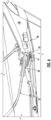
FIG. 5 is a closer perspective view from aft end of the vehicle showing the diffuser and air dam while the air dam is in the stowed position. -
FIG 6 . is a perspective side view showing the retention clip securing the air dam in the stowed position. - The present invention will be described more fully hereinafter with reference to the accompanying drawings, in which some, but not all embodiments of the inventions are shown. Indeed, these inventions may be embodied in many different forms and should not be construed as limited to the embodiments set forth herein; rather, these embodiments are provided so that this disclosure will satisfy applicable legal requirements.
- As used herein, it will be understood that the term "forward path of travel" means the direction the vehicle is moving when operated under normal conditions such that the longitudinal axis of the vehicle is parallel to the track and the front of the vehicle is facing forward. Likewise, a direction yawed from a forward path of travel means the longitudinal axis of the vehicle is rotated about its vertical axis, as occurring during a spin, such that the vehicle is moving in a direction toward its aft end.
- When a vehicle starts to spin (i.e. becomes yawed), the air passing over the hood, roof and rear deck can lower the air pressure, may cause lift, and in extreme circumstances, the lift may be sufficient to cause the vehicle to lift off the track. As the car rotates past 90° during spin-out, the rear or aft of the vehicle becomes the leading edge. The sudden lowering in air pressure on the vehicle's horizontal surface during the spin-out - when the yaw angle ranges from 70° to about 180° when the vehicle is going over 140 miles per hour - may cause the vehicle to lift off the surface of the track. This may result in the vehicle becoming airborne or flipping.
- In addressing safety and performance considerations, designers must consider the physical forces acting on the moving vehicle. In aerodynamic terms, these forces are expressed by lift, drag, weight, and thrust. Thrust is provided by the vehicle's engine and applied by the vehicle powertrain through the wheels and tires is counteracted by drag. Lift is created by the air flowing under the vehicle and over contoured surfaces. The lift force is responsible for causing vehicle to become airborne. It is therefore desirable to minimize lift forces the vehicle experiences and to counteract the lift forces with down force, even when the vehicle is not traveling in the forward direction.
- Lift may be counteracted by the vehicle's weight and spoilers or air dams on the vehicle surface in addition to louvres or ducting to direct airflow in a more desirable path through or around a vehicle to mitigate lift. Increased vehicle weight for the purpose of reducing lift negatively affects vehicle performance. Therefore, it is preferential to reduce lift by adding aerodynamic control surfaces and devices such as spoilers or air dams. Spoilers or air dams work by disrupting air flow and create a downward force on the vehicle. Downward force ("down force") or negative lift may be produced when there is a higher pressure on the top of the vehicle than there is pressure on the underside of the vehicle. Down force is primarily generated over horizontal areas such as the hood, roof, rear deck, spoilers (e.g., rear-deck spoilers and chin spoilers) and underside of the vehicle through diffusers.
- It will be understood by those familiar with competitive racing that conventional racing vehicles are designed to achieve the fastest possible speeds within the regulatory regime of a sanctioning body, such as the National Association for Stock Car Racing (NASCAR). Safety is a primary concern with vehicles achieving such high speeds and being capable of exceeding 200 mph. In this regard, the racing vehicle body should generally be designed to reduce drag along while increasing down force.
- Previous efforts to improve vehicle safety with regard to aerodynamic control surfaces saw the addition of roof flaps, which were added to vehicles to increase the down force acting on the vehicle during a spin. In their stowed position, roof flaps lie flat or relatively flat on the roof of the vehicle. When a vehicle becomes yawed, the roof flaps enter the deployed position, such that they are substantially raised from the roof. The negative pressure caused by high speed air traveling over the roof of the vehicle during a spin causes deployment of the roof flaps without requiring any deployment mechanism or mechanical trigger. The substantially vertical surface created by the deployed roof flaps spoils the air traveling over the surface of the roof, thereby increasing the downforce acting on a vehicle during a spin, while also functioning as an air-brake to slow the vehicle when it is traveling backwards, and possibly also functioning to induce spin to return the vehicle to a forward direction.
- While roof flaps have improved vehicle safety by reducing the likelihood of a vehicle becoming airborne while traveling backwards at substantial speeds, the Applicant has found additional improvements to supplement roof flaps and to better retain a vehicle spinning or traveling backwards at high speeds on the surface along which it is traveling.
- Accordingly, Applicant identified a need for an improved system and apparatus that increases the down force acting on a yawed vehicle during a high-speed spin and deflects the movement of air beneath the underside of the rear of the vehicle.
- As illustrated in
FIG. 1 , amotor vehicle 10 having afront end 11, anaft end 12, and aroof 14 is shown. Aroof flap 20 is shown in the stowed position and is hingedly attached to theroof 14 of thevehicle 10. Theroof flap 20 may rotate to a deployed position when the vehicle becomes yawed such that the trailing edge of theroof flap 20 is raised relative to theroof 14 of thevehicle 10 in response to air flowing under theroof flap 20 and raising it relative to theroof 14. Embodiments may include one or more roof flaps positioned proximate the aft end of theroof 14 of thevehicle 10. In some embodiments, such as for a vehicle designed for racing in a substantially circular or oval-shaped track in a counterclockwise direction, theroof flap 20 may be positioned near the right rear of the vehicle and may be angled 35-55 degrees counterclockwise from the centerline of the vehicle. In this way, if the vehicle becomes yawed, typically in the counterclockwise direction for a vehicle traveling counterclockwise on a circle or oval track, the angled right roof flap may respond quickly by entering the deployed position, thus disrupting air flow over the roof and creating additional down force. Positioning theroof flap 20 at an angle as described and illustrated enables theroof flap 20 to deploy while the vehicle is spinning and before the vehicle rotates a full 180 degrees traveling with the aft-end of the vehicle leading. Such early deployment may mitigate some of the aerodynamic forces that tend to lift the vehicle as it spins in the counterclockwise direction. - A
diffuser 30 is secured to the underside of theaft end 12 of thevehicle 10. When the vehicle is traveling at speed in the forward direction, thediffuser 30 accelerates air flow under the vehicle as it exits from under the vehicle and create an area of low pressure, thus creating down force on the vehicle. Thediffuser 30 may have at least afirst vane 31 andsecond vane 32 which extend substantially perpendicularly from thediffuser 30 creatingchannels - According to an example embodiment described herein, an
air dam 40 is shown in the stowed position and is hingedly secured to the vehicle at a first end 41 (shown inFigures 4 and5 ). The air dam is positioned between thefirst vane 31 andsecond vane 32 ofdiffuser 30. In the stowed position, a retention clip 50 (depicted inFigure 5 ), secures asecond end 42 of theair dam 40 to thediffuser 30 such that theair dam 40 does not interfere with the aerodynamic performance of thediffuser 30 of thevehicle 10 while traveling in the forward direction. - The
diffuser 30 andair dam 40 are further depicted inFIG. 2A-B . As previously described, thediffuser 30 may include afirst vane 31 andsecond vane 32 that extend substantially perpendicularly from thediffuser 30.FIG. 2A shows theair dam 40 in the stowed position.FIG. 2B shows the same perspective view but withair dam 40 in the deployed position. In either instance, theair dam 40 is located between thefirst vane 31 andsecond vane 32 of thediffuser 30. Theair dam 40 will move from the stowed position to the deployed position in response to the vehicle becoming yawed above a predefined speed. This deployment may be triggered through a number of actuation mechanisms such as through deployment of theroof flap 20 as described further below. In response to theair dam 40 being deployed, thesecond end 42 ofair dam 40 will rotate about its hinge such that it is spaced from thediffuser 30. The distance thesecond end 42 of theair dam 40 is spaced from thediffuser 30 may be determined by the length of the at least onevariable length connector 47 attached to thesecond end 42 ofair dam 40 and thediffuser 30. Thisvariable length connector 47 prohibits theair dam 40 from over-rotating and reaching a position where it may be damaged by the surface along which the vehicle is traveling, or reaching a position where the functionality of the air dam is decreased (e.g., when thesecond end 42 of the air dam rotates too far about the hinge). - Optionally, at least one of the
first vane 31 and thesecond vane 32 may include a tab or other structure to stop theair dam 40 from opening past the deployed position. The tab or other structure to stop theair dam 40 from opening past the deployed position may further serve to lock and retain theair dam 40 in the deployed position. Such a tab or other structure (e.g., a ledge on the vane or a pin extending from the vane) may be positioned proximate the interface between the deployedair dam 40 and thefirst vane 31 and/or thesecond vane 32. -
FIG. 3 shows theair dam 40 in the deployed position in greater detail. As shown, theair dam 40 further includes afirst edge 43 andsecond edge 44, wherein thefirst edge 43 is adjacent to thefirst vane 31 and thesecond edge 44 is adjacent thesecond vane 32 ofdiffuser 30. Specifically, afirst edge 43 of theair dam 40 extends between thefirst end 41 andsecond end 42 and abuts thefirst vane 31. Similarly, thesecond edge 44 of theair dam 40 extends between thefirst end 41 andsecond end 42 and abuts thesecond vane 32. In some embodiments, theair dam 40 is centered within thediffuser 30. Optionally, more than oneair dam 40 may be employed; however, multiple air dams may be employed using the same functionality of the single air dam disclosed through the illustrations provided herein. - When the
air dam 40 is in the deployed position and the vehicle is traveling in the aft direction or backwards, air is received in an opening defined by thesecond end 42 of the air dam, thefirst vane 31, thesecond vane 32, and thediffuser 30. The air is caught or dammed within this opening and bounded on all sides, including thefirst vane 31, thesecond vane 32, theair dam 40, and thediffuser 30. The flow of air into the opening creates an additional and substantial down force on the aft end of the vehicle in the area forward of the deployedair dam 10 as it travels in the aft direction, where the down force caused by theair dam 40 in the deployed position increases with increasing speed in the aft direction and helps to slow the vehicle based on the air resistance provided by theair dam 40. - As configured, the opening defined by the deployed
air dam 40 admits more flowing air as the degree of yaw of thevehicle 10 increases during a spin with respect to the forward path of travel. The increased amount of air flowing into the opening and pressing against the deployedair dam 40 distributes air pressure differentials acting on the surface of the vehicle in such a manner as to increase the amount of down force acting on the vehicle. Further, the maximum amount of down force is produced when the vehicle is yawed 180 degrees from the forward path of travel, i.e. traveling backwards. - According to some embodiments, when the
roof flap 20 deploys in response to the vehicle becoming yawed, a variable length cable 52 (shown inFigure 5 ) may connect theroof flap 20 to a mechanism to deploy theair dam 40 such that the air dam transitions to the deployed position responsive to theroof flap 20 deployment. In this way, both the deployedroof flap 20 andair dam 40 work in tandem to create down force on the yawed vehicle and prevent the vehicle from becoming airborne. - Turning now to
FIG. 4 , a different perspective showing the framework of theair dam 40 in the deployed position is shown. Thefirst end 41 of theair dam 40 can be seen hingedly secured to the underside of thevehicle 10 by ahinge 46. In some embodiments, there may be more than one hinge securing theair dam 40 to the underside of thevehicle 10. Optionally, theair dam 40 may be connected to the vehicle (and/or the diffuser 30) via a living hinge where a material, such as a reinforced rubber material secured along one edge to thefirst end 41 of theair dam 40 and along a second edge to the vehicle or thediffuser 30. As previously described, the at least onevariable length connector 47 may determine the distance thesecond end 42 of theair dam 40 is spaced from thediffuser 30. In some embodiments, the length of the variable length connector is long enough to maximize surface area coverage of theair dam 40 but short enough such that there is no danger of theair dam 40 reaching the track or surface along which the vehicle is traveling when deployed. - The at least one
variable length connector 47 may have afirst attachment 48a point near thesecond end 42 of theair dam 40 and asecond attachment 48b point on the underside of thediffuser 30. In some embodiments, thefirst attachment point 48a and thesecond attachment point 48b may be vertically aligned. In some embodiments, anadditional attachment 48c point may be included near thefirst end 41 of theair dam 40. An additionalvariable length connector 47b may be used to connect theadditional attachment point 48c and thevariable length connector 47. In this way, some of the force exerted on thevariable length connector 47 when theair dam 40 is deployed is offloaded. In some embodiments, one end of the additionalvariable length connector 47b may comprise a clip that freely moves about thevariable length connector 47. - In some embodiments, at least two
variable length connectors 47 connect theair dam 40 to thediffuser 30. The at least twovariable length connectors 47 may be spaced equidistant from the center of the diffuser and each have afirst attachment point 48a near thesecond end 42 of theair dam 40 and asecond attachment point 48b on the underside of thediffuser 30. In some embodiments, anadditional attachment point 48c may be included near thefirst end 41 of theair dam 40. Two additionalvariable length connectors 47b may be used to connect theadditional attachment point 48c to thevariable length connector 47. - In some embodiments, the
variable length connector 47 is comprised of a woven fabric. In this way, there may be an associated elasticity with the at least onevariable length connector 47 such that the connector may slightly stretch during the transition of theair dam 40 from the stowed position to deployed position. - While the example embodiment of
Figure 4 illustrates avariable length connector 47 to preclude theair dam 40 from opening or deploying beyond a predetermined position, as noted above, the vanes of thediffuser 30 may include mechanical stops that prevent theair dam 40 from opening beyond a predetermined position. Further, these mechanical stops may be tabs that retain the air dam in the deployed position once deployed. - Turning now to
FIG. 5 , a closeup view of theair dam 40 in the stowed position is shown. While in the stowed position, theair dam 40 is substantially flat against the underside of the vehicle such that is does not hinder the performance of thediffuser 30 of the vehicle and allows the diffuser to perform its aerodynamic function of creating downforce while the vehicle is traveling in the forward direction. Aretention clip 50 may secure the air dam in the stowed position. - The
air dam 40 may comprise aretention tab 45 positioned near the center of thesecond end 44 of the air dam. Theretention tab 45 may extend upward from near thesecond end 44 of theair dam 40. Theretention tab 45 may define an opening. In some embodiments, the opening may be sized such that apin 51 of theretention clip 50 may be received within theretention tab 45 opening. - As shown more clearly in
FIG. 6 , thepin 51 is inserted in the opening of theretention tab 45 thereby securing theair dam 40 in the stowed position. Avariable length cable 52 connects theretention clip 50 to theroof flap 20. In the event thevehicle 10 becomes yawed and is traveling above a predetermined speed, theretention clip 50 releases theair dam 40 from its currently stowed position to the deployed position. In some embodiments, this may be accomplished by theretention clip 50 withdrawing thepin 51 from theretention tab 45 opening. In some embodiments, this may be in response to theroof flap 20 transitioning from a stowed position to a deployed position. In some embodiments, this transition results in theroof flap 20 applying a considerable force on thepin 51 via thevariable length cable 52 such that thepin 51 is extracted from theretention tab 45 opening. - Advantageously, the described configuration allows for the passive deployment of the
air dam 40 such that there are no required computational components. In this way, theair dam 40 does not fail to deploy in situations where thevehicle 10 traveling above a predetermined speed becomes yawed. Similarly, theroof flap 20 also passively deploys. In operation, when the motor vehicle is traveling at a high rate of speed and begins moving in a direction of the aft end of the vehicle, e.g. becomes yawed, theroof flap 20 is activated when the low pressure of air moving across the roof creates pressure differentials and causes theroof flap 20 to transition from the stowed position to the deployed position. When theroof flap 20 is in the deployed position, air is caught by the roof flap generating a down force acts on, thevehicle 10. In some embodiments, the roof flap's transition from stowed to deployed is accomplished by means of springs such that the transition occurs almost instantaneously from when theroof flap 20 is activated by the pressure differential. - The
roof flap 20 may be connected toair dam 40 by way of avariable length cable 52,retention clip 50, andpin 51. In operation, when theroof flap 20 is deployed, the deployment is forceful enough to withdraw thepin 51 from theretention tab 45. Once thepin 51 is removed from theretention tab 45, theair dam 40 transitions from a stowed position to an open position due to gravitational force, impinging air on theair dam 40, or a combination thereof. Theair dam 40 will pivot from it'shinge 46 until it's at least onevariable length connector 47 connecting thesecond end 42 of theair dam 40 to thediffuser 30 is taut. Immediately upon the release of theair dam 40, a down force acts on theair dam 40 and thus, on thevehicle 10. The amount of down force produced on the yawed vehicle increases as the degree of yaw increases, up to a maximum amount of down force when the vehicle is yawed 180 degrees from the forward path of travel, i.e. traveling backwards. - In addition to producing down force,
air dam 40 in the deployed position may also function as an air brake to slow the vehicle. In this way, theair dam 40 increases the deceleration of the vehicle and thus reduces the vehicle velocity more quickly below the critical liftoff speed at which the vehicle would leave the ground.. By decreasing the speed of the vehicle, the driver may be able to regain control and take corrective action. - A vehicle entering a spin may not suffer any damage and may be capable of returning to racing without requiring a pit stop. The
air dam 40 described herein would not preclude the vehicle from continuing to race after deployment of theair dam 40. In an example embodiment in which theroof flap 20 causes theair dam 40 to deploy, as the roof flaps return to their stowed position flat along the roof, thevariable length cable 52 is no longer in tension, and the pin returns to a position whereby it can engage theretention clip 50 of theair dam 40. Theair dam 40 may, in some circumstances, be configured to be forced to the stowed position in response to the vehicle traveling at sufficient speed in the forward direction to drive air through thediffuser 30 and close theair dam 40 to the stowed position. In such a scenario, the retention clip may press against thepin 51 similar to a door latch until thepin 51 reaches the opening in the retention clip, where thepin 51 engages the opening and retains theair dam 40 in the stowed position. Optionally, air passing through thediffuser 30 may not be sufficient to move theair dam 40 to the stowed position, where manual closing of theair dam 40 may be necessary, such as through a pit stop. - While example embodiments provided herein describe a mechanical connection between the
roof flap 20 and theair dam 40, namely avariable length cable 52 that releases theretention clip 50 in response to theroof flap 20 deploying, embodiments may use other mechanisms for deploying the air dam. For example, the mechanism may be electromechanical, whereby a sensor detects deployment of theroof flap 20 and causes theair dam 40 to deploy, such as through release of a mechanical clip or deactivation of an electro-magnetic latch that held theair dam 40 in the stowed position. Optionally, deployment of theair dam 40 may be performed in response to signals from one or more sensors indicating that the vehicle has entered a spin. Sensors such as directional sensors, one or more gyroscopes, an inertial measurement unit (IMU), wheel sensors, etc. Various mechanisms described herein cause theair dam 40 to deploy when the vehicle enters a spin or is sufficiently yawed to deploy theair dam 40 through mechanical or electromechanical deployment. - This invention has been described in detail with particular reference to preferred embodiments and the operation thereof, but it is understood that variations and modifications may be made, as long as they fall under the scope of the appended claims.
Claims (15)
- An apparatus comprising:an air dam (40) having a first end (41) and a second end (42), wherein the first end is hingedly secured to the vehicle;wherein the air dam defines a stowed position and a deployed position;characterized by:wherein in the stowed position, the retention clip secures the second end of the air dam to the diffuser, wherein in a deployed position, the second end is spaced from the diffuser, and wherein the air dam moves from the stowed position to the deployed position in response to the retention clip releasing the air dam and at least one of gravity or impinging air on the air dam driving the second end of the air dam away from the diffuser.a retention clip (50); anda diffuser (30) secured to an underside of an aft end (12) of a vehicle (10);
- The apparatus of claim 1, wherein the diffuser (30) comprises at least a first vane (31) and a second vane (32), wherein the first vane and the second vane extend perpendicularly from the diffuser, wherein the air dam (40) defines a first edge (43) extending between the first end (41) and the second end (42) and a second edge (44) extending between the first end and the second end, wherein the first edge abuts the first vane and the second edge abuts the second vane.
- The apparatus of claim 2, wherein in the deployed position, the first edge (43) of the air dam (40) abuts the first vane (31) and the second edge (44) of the air dam abuts the second vane (32), wherein an opening is defined by the diffuser (30), the second end of the air dam, the first vane, and the second vane, and wherein air is received into the opening in response to the vehicle (10) moving in a direction of the aft end (12) of the vehicle.
- The apparatus of claim 3, wherein air received into the opening in response to the vehicle (10) moving in a direction of the aft end (12) of the vehicle produces a downward force on the aft end of the vehicle.
- The apparatus of any of claims 2-4, wherein at least one of the first vane (31) or second vane (32) comprise a structure to prevent the air dam (40) from opening beyond the deployed position.
- The apparatus of any of claims 2-5, wherein at least one of the first vane (31) or second vane (32) comprise a structure to lock and retain the air dam (40) in the deployed position.
- The apparatus of any preceding claim, wherein the retention clip (50) releases the air dam (40) in response to the vehicle (10) moving in a direction of the aft end (12) of the vehicle above a predetermined speed.
- The apparatus of any preceding claim, wherein the retention clip (50) comprises a pin (51) received within an opening of a portion of the air dam (40), wherein the retention clip releasing the air dam comprises withdrawing the pin from the opening.
- The apparatus of claim 8, wherein the air dam (40) comprises a retention tab (45), wherein the opening is defined within the retention tab.
- The apparatus of any preceding claim, wherein the air dam (40) functions as an air brake to slow the vehicle (10) in response to being in the deployed position and the vehicle traveling in a direction of the aft end (12) of the vehicle.
- The apparatus of any preceding claim, wherein the air dam (40) produces a downward force on the aft end (12) of the vehicle (10) in response to being in the deployed position and the vehicle traveling in a direction of the aft end of the vehicle.
- A system comprising:a roof flap (20) hingedly attached to a roof (14) of a vehicle (10) and defining a stowed position in which the roof flap lies flat relative to the roof of the vehicle and a deployed position in which a trailing edge of the roof flap is raised relative to the roof of the vehicle; andan air dam (40) hingedly secured to an underside of the vehicle proximate an aft end (12) of the vehicle, wherein the air dam defines a stowed position in which the air dam is raised relative to the underside of the vehicle and a deployed position in which the air dam is lowered relative to the underside of the vehicle;characterized by a retention clip (50) securing the air dam in the stowed position, wherein the air dam moves from the stowed position to the deployed position in response to the retention clip releasing the air dam, and wherein the retention clip releases the air dam in response to the roof flap moving to the deployed position.
- The system of claim 12, wherein the roof flap (20) moves to the deployed position in response to the vehicle (10) moving in a direction toward the aft end (12) of the vehicle.
- The system of claim 12 or 13, wherein the roof flap (20) moves to the deployed position in response to the vehicle (10) moving in a direction toward the aft end (12) of the vehicle above a predefined speed.
- The system of any of claims 12-14, wherein the air dam (40), in the deployed position, produces a downward force on the aft end (12) of the vehicle (10) in response to the vehicle traveling in a direction toward the aft end of the vehicle above a predefined speed.
Applications Claiming Priority (1)
| Application Number | Priority Date | Filing Date | Title |
|---|---|---|---|
| US17/082,514 US11390335B2 (en) | 2020-10-28 | 2020-10-28 | System and apparatus for increasing downward force exerted on the aft end of a motor vehicle |
Publications (2)
| Publication Number | Publication Date |
|---|---|
| EP3992062A1 EP3992062A1 (en) | 2022-05-04 |
| EP3992062B1 true EP3992062B1 (en) | 2023-09-06 |
Family
ID=78414338
Family Applications (1)
| Application Number | Title | Priority Date | Filing Date |
|---|---|---|---|
| EP21205236.9A Active EP3992062B1 (en) | 2020-10-28 | 2021-10-28 | System and apparatus for increasing downward force exerted on the aft end of a motor vehicle |
Country Status (4)
| Country | Link |
|---|---|
| US (1) | US11390335B2 (en) |
| EP (1) | EP3992062B1 (en) |
| CA (1) | CA3136013C (en) |
| MX (1) | MX2021013114A (en) |
Families Citing this family (4)
| Publication number | Priority date | Publication date | Assignee | Title |
|---|---|---|---|---|
| US12583534B2 (en) * | 2021-08-09 | 2026-03-24 | Marc Gregory Martino | Vehicle with a diffuser mounted thruster |
| CN118205636A (en) * | 2022-12-16 | 2024-06-18 | 武汉路特斯汽车有限公司 | Vehicle aerodynamic kit control system and vehicle |
| US12612122B2 (en) * | 2023-11-03 | 2026-04-28 | Obinna Hyacinth Ehirim | Rolling diffuser ramp for motor vehicle |
| KR20260013586A (en) * | 2024-07-22 | 2026-01-29 | 현대자동차주식회사 | System and method of controlling vehicle |
Family Cites Families (30)
| Publication number | Priority date | Publication date | Assignee | Title |
|---|---|---|---|---|
| US1389757A (en) | 1919-09-20 | 1921-09-06 | Caleb V Haynes | Airplane-brake |
| US2149161A (en) | 1937-02-10 | 1939-02-28 | Thomas J Byrnes | Air resistor |
| US2979165A (en) | 1960-04-07 | 1961-04-11 | Mccambridge Joseph | Fluid-dynamic emergency brakes |
| US3225376A (en) | 1964-05-04 | 1965-12-28 | Gen Motors Corp | Concealed windshield wiper mechanism |
| US3596974A (en) | 1969-03-10 | 1971-08-03 | John Q Adams | Air current deflecting device |
| US4160494A (en) | 1977-07-28 | 1979-07-10 | Mccambridge Joseph | Fluid-dynamic emergency brakes |
| US4256339A (en) | 1977-11-04 | 1981-03-17 | Four Star Corporation | Velocity responsive deflector blade with self-alignment pivotal mounting |
| US4179154A (en) | 1977-11-04 | 1979-12-18 | Four Star Corporation | Air velocity responsive deflector |
| WO1980001672A1 (en) | 1979-02-09 | 1980-08-21 | T Miwa | Device for enhancing safety of pneumatic characteristic of vehicle |
| DE3115150A1 (en) | 1981-04-15 | 1982-11-04 | Volkswagenwerk Ag, 3180 Wolfsburg | Device which acts aerodynamically for reducing the side-wind sensitivity of a vehicle |
| DE3580290D1 (en) | 1984-02-29 | 1990-12-06 | Nissan Motor | MOTOR VEHICLE WIND DEFLECTOR WITH ADJUSTABLE ANGLE. |
| JPH0631014B2 (en) | 1984-12-07 | 1994-04-27 | 勉 三輪 | Aerodynamic vehicle |
| US4925236A (en) | 1987-05-22 | 1990-05-15 | Nippondenso Co., Ltd. | Automotive air spoiler device |
| JPH0382681A (en) | 1989-08-28 | 1991-04-08 | Nissan Motor Co Ltd | Running stability maintaining device |
| JPH048681A (en) | 1990-04-24 | 1992-01-13 | Honda Motor Co Ltd | Vehicle rear body structure |
| JP2755001B2 (en) | 1992-01-09 | 1998-05-20 | 三菱自動車工業株式会社 | Movable rear spoiler for vehicles |
| US5222438A (en) | 1992-07-17 | 1993-06-29 | Grumman Aerospace Corporation | Aerodynamic fairing/brake for high-speed trains |
| US5374098A (en) | 1994-01-14 | 1994-12-20 | National Association For Stock Car Auto Racing, Inc. | Aerodynamic stabilizer for use with a motor vehicle |
| US5544931A (en) | 1994-01-14 | 1996-08-13 | National Association For Stock Car Auto Racing, Inc. | Aerodynamic stabilizer for use with a motor vehicle |
| US5454619A (en) * | 1994-06-09 | 1995-10-03 | Haraway, Jr.; William M. | Aerodynamically responsive vehicular safety spoiler system |
| US6196620B1 (en) | 1999-03-19 | 2001-03-06 | William H. Haraway, Jr. | Aerodynamically responsive vehicular undercarriage safety spoiler system |
| US6637805B2 (en) * | 2001-10-19 | 2003-10-28 | Clayton B. Rees | Apparatus and method for increasing downward force exerted on a spinning vehicle |
| US6742831B2 (en) * | 2001-10-19 | 2004-06-01 | Clayton B. Rees | Apparatus and method for increasing downward force exerted on a spinning vehicle |
| DE102011112514A1 (en) | 2011-09-07 | 2013-03-07 | Apollo Vredestein B.V. | Air guiding device of a motor vehicle |
| DE102013105843B4 (en) * | 2013-06-06 | 2022-08-04 | Dr. Ing. H.C. F. Porsche Aktiengesellschaft | Motor vehicle with an adjustable air guide element |
| DE102015118076A1 (en) * | 2015-10-23 | 2017-04-27 | Dr. Ing. H.C. F. Porsche Aktiengesellschaft | Heckdiffusoranordnung for a motor vehicle |
| US9950611B2 (en) * | 2016-03-15 | 2018-04-24 | Ford Global Technologies, Llc | Aerodynamic body panel system for air flow management at a rear underside of a motor vehicle |
| US9868479B2 (en) * | 2016-04-13 | 2018-01-16 | Fca Us Llc | Configurable rear underbody aerodynamic diffuser |
| DE102016005060A1 (en) * | 2016-04-28 | 2016-09-29 | Daimler Ag | Diffuser for a motor vehicle, especially a passenger car |
| US9957000B1 (en) | 2017-02-25 | 2018-05-01 | Obinna Hyacinth Ehirim | Downforce-enhancement of an automobile-type diffuser using two devices |
-
2020
- 2020-10-28 US US17/082,514 patent/US11390335B2/en active Active
-
2021
- 2021-10-26 MX MX2021013114A patent/MX2021013114A/en unknown
- 2021-10-27 CA CA3136013A patent/CA3136013C/en active Active
- 2021-10-28 EP EP21205236.9A patent/EP3992062B1/en active Active
Also Published As
| Publication number | Publication date |
|---|---|
| EP3992062A1 (en) | 2022-05-04 |
| MX2021013114A (en) | 2022-04-29 |
| CA3136013C (en) | 2025-11-18 |
| US11390335B2 (en) | 2022-07-19 |
| CA3136013A1 (en) | 2022-04-28 |
| US20220126932A1 (en) | 2022-04-28 |
Similar Documents
| Publication | Publication Date | Title |
|---|---|---|
| CA3136013C (en) | System and apparatus for increasing downward force exerted on the aft end of a motor vehicle | |
| US5908217A (en) | Pneumatic aerodynamic control and drag-reduction system for ground vehicles | |
| US5374098A (en) | Aerodynamic stabilizer for use with a motor vehicle | |
| US5374013A (en) | Method and apparatus for reducing drag on a moving body | |
| US10730570B2 (en) | Enhanced vehicle efficiency using airfoil to raise rear wheels above road surface | |
| US10589801B2 (en) | Vehicle propulsive aerodynamic elements | |
| CN106476913A (en) | Automobile active skirtboard and its control method | |
| US9630662B2 (en) | Vehicle having vehicle-body side surfaces provided with airflow passages | |
| US5544931A (en) | Aerodynamic stabilizer for use with a motor vehicle | |
| US9266571B2 (en) | Speed-adaptive wing for drag reduction | |
| US6742831B2 (en) | Apparatus and method for increasing downward force exerted on a spinning vehicle | |
| MXPA01011776A (en) | Front hood assembly. | |
| CN114502454B (en) | Air guide device and vehicle having such an air guide device | |
| GB2269142A (en) | Motor vehicle having ground effect producing aerodynamic surfaces | |
| KR101501289B1 (en) | The rear portion of the vehicle | |
| HK40073981B (en) | System and apparatus for increasing downward force exerted on the aft end of a motor vehicle | |
| HK40073981A (en) | System and apparatus for increasing downward force exerted on the aft end of a motor vehicle | |
| EP3717350A1 (en) | A canopy control system | |
| JP6485976B2 (en) | Vehicle rollover prevention device | |
| US6106054A (en) | Device for improving driveability of a road vehicle and road vehicle using such a device | |
| JP2004026034A (en) | Vertical takeoff and landing aircraft | |
| US6010222A (en) | Aerodynamic mirror exterior shell | |
| US5927795A (en) | Vehicle aerodynamic stability device | |
| US20140076419A1 (en) | Self adjusting deturbulator enhanced flap and wind deflector | |
| WO2001036255A1 (en) | Traction enhancement apparatus for a vehicle |
Legal Events
| Date | Code | Title | Description |
|---|---|---|---|
| PUAI | Public reference made under article 153(3) epc to a published international application that has entered the european phase |
Free format text: ORIGINAL CODE: 0009012 |
|
| STAA | Information on the status of an ep patent application or granted ep patent |
Free format text: STATUS: THE APPLICATION HAS BEEN PUBLISHED |
|
| AK | Designated contracting states |
Kind code of ref document: A1 Designated state(s): AL AT BE BG CH CY CZ DE DK EE ES FI FR GB GR HR HU IE IS IT LI LT LU LV MC MK MT NL NO PL PT RO RS SE SI SK SM TR |
|
| STAA | Information on the status of an ep patent application or granted ep patent |
Free format text: STATUS: REQUEST FOR EXAMINATION WAS MADE |
|
| 17P | Request for examination filed |
Effective date: 20220921 |
|
| RBV | Designated contracting states (corrected) |
Designated state(s): AL AT BE BG CH CY CZ DE DK EE ES FI FR GB GR HR HU IE IS IT LI LT LU LV MC MK MT NL NO PL PT RO RS SE SI SK SM TR |
|
| REG | Reference to a national code |
Ref country code: HK Ref legal event code: DE Ref document number: 40073981 Country of ref document: HK |
|
| GRAP | Despatch of communication of intention to grant a patent |
Free format text: ORIGINAL CODE: EPIDOSNIGR1 |
|
| STAA | Information on the status of an ep patent application or granted ep patent |
Free format text: STATUS: GRANT OF PATENT IS INTENDED |
|
| INTG | Intention to grant announced |
Effective date: 20230331 |
|
| RIC1 | Information provided on ipc code assigned before grant |
Ipc: B62D 37/02 20060101ALI20230317BHEP Ipc: B62D 35/02 20060101ALI20230317BHEP Ipc: B62D 35/00 20060101AFI20230317BHEP |
|
| GRAS | Grant fee paid |
Free format text: ORIGINAL CODE: EPIDOSNIGR3 |
|
| GRAA | (expected) grant |
Free format text: ORIGINAL CODE: 0009210 |
|
| STAA | Information on the status of an ep patent application or granted ep patent |
Free format text: STATUS: THE PATENT HAS BEEN GRANTED |
|
| AK | Designated contracting states |
Kind code of ref document: B1 Designated state(s): AL AT BE BG CH CY CZ DE DK EE ES FI FR GB GR HR HU IE IS IT LI LT LU LV MC MK MT NL NO PL PT RO RS SE SI SK SM TR |
|
| REG | Reference to a national code |
Ref country code: GB Ref legal event code: FG4D |
|
| REG | Reference to a national code |
Ref country code: CH Ref legal event code: EP |
|
| REG | Reference to a national code |
Ref country code: IE Ref legal event code: FG4D |
|
| REG | Reference to a national code |
Ref country code: DE Ref legal event code: R096 Ref document number: 602021004926 Country of ref document: DE |
|
| REG | Reference to a national code |
Ref country code: LT Ref legal event code: MG9D |
|
| REG | Reference to a national code |
Ref country code: NL Ref legal event code: MP Effective date: 20230906 |
|
| PG25 | Lapsed in a contracting state [announced via postgrant information from national office to epo] |
Ref country code: GR Free format text: LAPSE BECAUSE OF FAILURE TO SUBMIT A TRANSLATION OF THE DESCRIPTION OR TO PAY THE FEE WITHIN THE PRESCRIBED TIME-LIMIT Effective date: 20231207 |
|
| PG25 | Lapsed in a contracting state [announced via postgrant information from national office to epo] |
Ref country code: SE Free format text: LAPSE BECAUSE OF FAILURE TO SUBMIT A TRANSLATION OF THE DESCRIPTION OR TO PAY THE FEE WITHIN THE PRESCRIBED TIME-LIMIT Effective date: 20230906 Ref country code: RS Free format text: LAPSE BECAUSE OF FAILURE TO SUBMIT A TRANSLATION OF THE DESCRIPTION OR TO PAY THE FEE WITHIN THE PRESCRIBED TIME-LIMIT Effective date: 20230906 Ref country code: NO Free format text: LAPSE BECAUSE OF FAILURE TO SUBMIT A TRANSLATION OF THE DESCRIPTION OR TO PAY THE FEE WITHIN THE PRESCRIBED TIME-LIMIT Effective date: 20231206 Ref country code: LV Free format text: LAPSE BECAUSE OF FAILURE TO SUBMIT A TRANSLATION OF THE DESCRIPTION OR TO PAY THE FEE WITHIN THE PRESCRIBED TIME-LIMIT Effective date: 20230906 Ref country code: LT Free format text: LAPSE BECAUSE OF FAILURE TO SUBMIT A TRANSLATION OF THE DESCRIPTION OR TO PAY THE FEE WITHIN THE PRESCRIBED TIME-LIMIT Effective date: 20230906 Ref country code: HR Free format text: LAPSE BECAUSE OF FAILURE TO SUBMIT A TRANSLATION OF THE DESCRIPTION OR TO PAY THE FEE WITHIN THE PRESCRIBED TIME-LIMIT Effective date: 20230906 Ref country code: GR Free format text: LAPSE BECAUSE OF FAILURE TO SUBMIT A TRANSLATION OF THE DESCRIPTION OR TO PAY THE FEE WITHIN THE PRESCRIBED TIME-LIMIT Effective date: 20231207 Ref country code: FI Free format text: LAPSE BECAUSE OF FAILURE TO SUBMIT A TRANSLATION OF THE DESCRIPTION OR TO PAY THE FEE WITHIN THE PRESCRIBED TIME-LIMIT Effective date: 20230906 |
|
| REG | Reference to a national code |
Ref country code: AT Ref legal event code: MK05 Ref document number: 1608201 Country of ref document: AT Kind code of ref document: T Effective date: 20230906 |
|
| PG25 | Lapsed in a contracting state [announced via postgrant information from national office to epo] |
Ref country code: NL Free format text: LAPSE BECAUSE OF FAILURE TO SUBMIT A TRANSLATION OF THE DESCRIPTION OR TO PAY THE FEE WITHIN THE PRESCRIBED TIME-LIMIT Effective date: 20230906 |
|
| PG25 | Lapsed in a contracting state [announced via postgrant information from national office to epo] |
Ref country code: IS Free format text: LAPSE BECAUSE OF FAILURE TO SUBMIT A TRANSLATION OF THE DESCRIPTION OR TO PAY THE FEE WITHIN THE PRESCRIBED TIME-LIMIT Effective date: 20240106 |
|
| PG25 | Lapsed in a contracting state [announced via postgrant information from national office to epo] |
Ref country code: AT Free format text: LAPSE BECAUSE OF FAILURE TO SUBMIT A TRANSLATION OF THE DESCRIPTION OR TO PAY THE FEE WITHIN THE PRESCRIBED TIME-LIMIT Effective date: 20230906 |
|
| PG25 | Lapsed in a contracting state [announced via postgrant information from national office to epo] |
Ref country code: ES Free format text: LAPSE BECAUSE OF FAILURE TO SUBMIT A TRANSLATION OF THE DESCRIPTION OR TO PAY THE FEE WITHIN THE PRESCRIBED TIME-LIMIT Effective date: 20230906 |
|
| PG25 | Lapsed in a contracting state [announced via postgrant information from national office to epo] |
Ref country code: SM Free format text: LAPSE BECAUSE OF FAILURE TO SUBMIT A TRANSLATION OF THE DESCRIPTION OR TO PAY THE FEE WITHIN THE PRESCRIBED TIME-LIMIT Effective date: 20230906 Ref country code: RO Free format text: LAPSE BECAUSE OF FAILURE TO SUBMIT A TRANSLATION OF THE DESCRIPTION OR TO PAY THE FEE WITHIN THE PRESCRIBED TIME-LIMIT Effective date: 20230906 Ref country code: IS Free format text: LAPSE BECAUSE OF FAILURE TO SUBMIT A TRANSLATION OF THE DESCRIPTION OR TO PAY THE FEE WITHIN THE PRESCRIBED TIME-LIMIT Effective date: 20240106 Ref country code: ES Free format text: LAPSE BECAUSE OF FAILURE TO SUBMIT A TRANSLATION OF THE DESCRIPTION OR TO PAY THE FEE WITHIN THE PRESCRIBED TIME-LIMIT Effective date: 20230906 Ref country code: EE Free format text: LAPSE BECAUSE OF FAILURE TO SUBMIT A TRANSLATION OF THE DESCRIPTION OR TO PAY THE FEE WITHIN THE PRESCRIBED TIME-LIMIT Effective date: 20230906 Ref country code: CZ Free format text: LAPSE BECAUSE OF FAILURE TO SUBMIT A TRANSLATION OF THE DESCRIPTION OR TO PAY THE FEE WITHIN THE PRESCRIBED TIME-LIMIT Effective date: 20230906 Ref country code: AT Free format text: LAPSE BECAUSE OF FAILURE TO SUBMIT A TRANSLATION OF THE DESCRIPTION OR TO PAY THE FEE WITHIN THE PRESCRIBED TIME-LIMIT Effective date: 20230906 Ref country code: SK Free format text: LAPSE BECAUSE OF FAILURE TO SUBMIT A TRANSLATION OF THE DESCRIPTION OR TO PAY THE FEE WITHIN THE PRESCRIBED TIME-LIMIT Effective date: 20230906 Ref country code: PT Free format text: LAPSE BECAUSE OF FAILURE TO SUBMIT A TRANSLATION OF THE DESCRIPTION OR TO PAY THE FEE WITHIN THE PRESCRIBED TIME-LIMIT Effective date: 20240108 |
|
| PG25 | Lapsed in a contracting state [announced via postgrant information from national office to epo] |
Ref country code: PL Free format text: LAPSE BECAUSE OF FAILURE TO SUBMIT A TRANSLATION OF THE DESCRIPTION OR TO PAY THE FEE WITHIN THE PRESCRIBED TIME-LIMIT Effective date: 20230906 Ref country code: IT Free format text: LAPSE BECAUSE OF FAILURE TO SUBMIT A TRANSLATION OF THE DESCRIPTION OR TO PAY THE FEE WITHIN THE PRESCRIBED TIME-LIMIT Effective date: 20230906 |
|
| REG | Reference to a national code |
Ref country code: DE Ref legal event code: R097 Ref document number: 602021004926 Country of ref document: DE |
|
| REG | Reference to a national code |
Ref country code: BE Ref legal event code: MM Effective date: 20231031 |
|
| PG25 | Lapsed in a contracting state [announced via postgrant information from national office to epo] |
Ref country code: LU Free format text: LAPSE BECAUSE OF NON-PAYMENT OF DUE FEES Effective date: 20231028 |
|
| PG25 | Lapsed in a contracting state [announced via postgrant information from national office to epo] |
Ref country code: LU Free format text: LAPSE BECAUSE OF NON-PAYMENT OF DUE FEES Effective date: 20231028 |
|
| PG25 | Lapsed in a contracting state [announced via postgrant information from national office to epo] |
Ref country code: MC Free format text: LAPSE BECAUSE OF FAILURE TO SUBMIT A TRANSLATION OF THE DESCRIPTION OR TO PAY THE FEE WITHIN THE PRESCRIBED TIME-LIMIT Effective date: 20230906 |
|
| PG25 | Lapsed in a contracting state [announced via postgrant information from national office to epo] |
Ref country code: DK Free format text: LAPSE BECAUSE OF FAILURE TO SUBMIT A TRANSLATION OF THE DESCRIPTION OR TO PAY THE FEE WITHIN THE PRESCRIBED TIME-LIMIT Effective date: 20230906 |
|
| PLBE | No opposition filed within time limit |
Free format text: ORIGINAL CODE: 0009261 |
|
| STAA | Information on the status of an ep patent application or granted ep patent |
Free format text: STATUS: NO OPPOSITION FILED WITHIN TIME LIMIT |
|
| PG25 | Lapsed in a contracting state [announced via postgrant information from national office to epo] |
Ref country code: MC Free format text: LAPSE BECAUSE OF FAILURE TO SUBMIT A TRANSLATION OF THE DESCRIPTION OR TO PAY THE FEE WITHIN THE PRESCRIBED TIME-LIMIT Effective date: 20230906 Ref country code: DK Free format text: LAPSE BECAUSE OF FAILURE TO SUBMIT A TRANSLATION OF THE DESCRIPTION OR TO PAY THE FEE WITHIN THE PRESCRIBED TIME-LIMIT Effective date: 20230906 Ref country code: SI Free format text: LAPSE BECAUSE OF FAILURE TO SUBMIT A TRANSLATION OF THE DESCRIPTION OR TO PAY THE FEE WITHIN THE PRESCRIBED TIME-LIMIT Effective date: 20230906 |
|
| 26N | No opposition filed |
Effective date: 20240607 |
|
| PG25 | Lapsed in a contracting state [announced via postgrant information from national office to epo] |
Ref country code: BE Free format text: LAPSE BECAUSE OF NON-PAYMENT OF DUE FEES Effective date: 20231031 |
|
| PG25 | Lapsed in a contracting state [announced via postgrant information from national office to epo] |
Ref country code: IE Free format text: LAPSE BECAUSE OF NON-PAYMENT OF DUE FEES Effective date: 20231028 |
|
| PG25 | Lapsed in a contracting state [announced via postgrant information from national office to epo] |
Ref country code: IE Free format text: LAPSE BECAUSE OF NON-PAYMENT OF DUE FEES Effective date: 20231028 |
|
| PG25 | Lapsed in a contracting state [announced via postgrant information from national office to epo] |
Ref country code: BG Free format text: LAPSE BECAUSE OF FAILURE TO SUBMIT A TRANSLATION OF THE DESCRIPTION OR TO PAY THE FEE WITHIN THE PRESCRIBED TIME-LIMIT Effective date: 20230906 |
|
| PG25 | Lapsed in a contracting state [announced via postgrant information from national office to epo] |
Ref country code: BG Free format text: LAPSE BECAUSE OF FAILURE TO SUBMIT A TRANSLATION OF THE DESCRIPTION OR TO PAY THE FEE WITHIN THE PRESCRIBED TIME-LIMIT Effective date: 20230906 |
|
| REG | Reference to a national code |
Ref country code: CH Ref legal event code: PL |
|
| PG25 | Lapsed in a contracting state [announced via postgrant information from national office to epo] |
Ref country code: CH Free format text: LAPSE BECAUSE OF NON-PAYMENT OF DUE FEES Effective date: 20241031 |
|
| PG25 | Lapsed in a contracting state [announced via postgrant information from national office to epo] |
Ref country code: CY Free format text: LAPSE BECAUSE OF FAILURE TO SUBMIT A TRANSLATION OF THE DESCRIPTION OR TO PAY THE FEE WITHIN THE PRESCRIBED TIME-LIMIT; INVALID AB INITIO Effective date: 20211028 |
|
| PG25 | Lapsed in a contracting state [announced via postgrant information from national office to epo] |
Ref country code: TR Free format text: LAPSE BECAUSE OF FAILURE TO SUBMIT A TRANSLATION OF THE DESCRIPTION OR TO PAY THE FEE WITHIN THE PRESCRIBED TIME-LIMIT Effective date: 20230906 |
|
| PGFP | Annual fee paid to national office [announced via postgrant information from national office to epo] |
Ref country code: DE Payment date: 20251013 Year of fee payment: 5 |
|
| PGFP | Annual fee paid to national office [announced via postgrant information from national office to epo] |
Ref country code: GB Payment date: 20251020 Year of fee payment: 5 |
|
| PGFP | Annual fee paid to national office [announced via postgrant information from national office to epo] |
Ref country code: FR Payment date: 20251017 Year of fee payment: 5 |
|
| PG25 | Lapsed in a contracting state [announced via postgrant information from national office to epo] |
Ref country code: HU Free format text: LAPSE BECAUSE OF FAILURE TO SUBMIT A TRANSLATION OF THE DESCRIPTION OR TO PAY THE FEE WITHIN THE PRESCRIBED TIME-LIMIT; INVALID AB INITIO Effective date: 20211028 |