EP3992031A1 - Drive control system - Google Patents
Drive control system Download PDFInfo
- Publication number
- EP3992031A1 EP3992031A1 EP20833690.9A EP20833690A EP3992031A1 EP 3992031 A1 EP3992031 A1 EP 3992031A1 EP 20833690 A EP20833690 A EP 20833690A EP 3992031 A1 EP3992031 A1 EP 3992031A1
- Authority
- EP
- European Patent Office
- Prior art keywords
- transportation
- load collapse
- control system
- drive control
- transportation vehicle
- Prior art date
- Legal status (The legal status is an assumption and is not a legal conclusion. Google has not performed a legal analysis and makes no representation as to the accuracy of the status listed.)
- Withdrawn
Links
Images


Classifications
-
- B—PERFORMING OPERATIONS; TRANSPORTING
- B60—VEHICLES IN GENERAL
- B60W—CONJOINT CONTROL OF VEHICLE SUB-UNITS OF DIFFERENT TYPE OR DIFFERENT FUNCTION; CONTROL SYSTEMS SPECIALLY ADAPTED FOR HYBRID VEHICLES; ROAD VEHICLE DRIVE CONTROL SYSTEMS FOR PURPOSES NOT RELATED TO THE CONTROL OF A PARTICULAR SUB-UNIT
- B60W40/00—Estimation or calculation of non-directly measurable driving parameters for road vehicle drive control systems not related to the control of a particular sub unit, e.g. by using mathematical models
- B60W40/12—Estimation or calculation of non-directly measurable driving parameters for road vehicle drive control systems not related to the control of a particular sub unit, e.g. by using mathematical models related to parameters of the vehicle itself, e.g. tyre models
- B60W40/13—Load or weight
-
- B—PERFORMING OPERATIONS; TRANSPORTING
- B60—VEHICLES IN GENERAL
- B60Q—ARRANGEMENT OF SIGNALLING OR LIGHTING DEVICES, THE MOUNTING OR SUPPORTING THEREOF OR CIRCUITS THEREFOR, FOR VEHICLES IN GENERAL
- B60Q9/00—Arrangement or adaptation of signal devices not provided for in one of main groups B60Q1/00 - B60Q7/00, e.g. haptic signalling
-
- B—PERFORMING OPERATIONS; TRANSPORTING
- B60—VEHICLES IN GENERAL
- B60P—VEHICLES ADAPTED FOR LOAD TRANSPORTATION OR TO TRANSPORT, TO CARRY, OR TO COMPRISE SPECIAL LOADS OR OBJECTS
- B60P9/00—Other vehicles predominantly for carrying loads, e.g. load carrying vehicles convertible for an intended purpose
-
- B—PERFORMING OPERATIONS; TRANSPORTING
- B60—VEHICLES IN GENERAL
- B60W—CONJOINT CONTROL OF VEHICLE SUB-UNITS OF DIFFERENT TYPE OR DIFFERENT FUNCTION; CONTROL SYSTEMS SPECIALLY ADAPTED FOR HYBRID VEHICLES; ROAD VEHICLE DRIVE CONTROL SYSTEMS FOR PURPOSES NOT RELATED TO THE CONTROL OF A PARTICULAR SUB-UNIT
- B60W40/00—Estimation or calculation of non-directly measurable driving parameters for road vehicle drive control systems not related to the control of a particular sub unit, e.g. by using mathematical models
- B60W40/02—Estimation or calculation of non-directly measurable driving parameters for road vehicle drive control systems not related to the control of a particular sub unit, e.g. by using mathematical models related to ambient conditions
- B60W40/04—Traffic conditions
-
- B—PERFORMING OPERATIONS; TRANSPORTING
- B60—VEHICLES IN GENERAL
- B60W—CONJOINT CONTROL OF VEHICLE SUB-UNITS OF DIFFERENT TYPE OR DIFFERENT FUNCTION; CONTROL SYSTEMS SPECIALLY ADAPTED FOR HYBRID VEHICLES; ROAD VEHICLE DRIVE CONTROL SYSTEMS FOR PURPOSES NOT RELATED TO THE CONTROL OF A PARTICULAR SUB-UNIT
- B60W60/00—Drive control systems specially adapted for autonomous road vehicles
- B60W60/001—Planning or execution of driving tasks
-
- G—PHYSICS
- G01—MEASURING; TESTING
- G01B—MEASURING LENGTH, THICKNESS OR SIMILAR LINEAR DIMENSIONS; MEASURING ANGLES; MEASURING AREAS; MEASURING IRREGULARITIES OF SURFACES OR CONTOURS
- G01B11/00—Measuring arrangements characterised by the use of optical techniques
- G01B11/02—Measuring arrangements characterised by the use of optical techniques for measuring length, width or thickness
- G01B11/026—Measuring arrangements characterised by the use of optical techniques for measuring length, width or thickness by measuring distance between sensor and object
-
- G—PHYSICS
- G01—MEASURING; TESTING
- G01S—RADIO DIRECTION-FINDING; RADIO NAVIGATION; DETERMINING DISTANCE OR VELOCITY BY USE OF RADIO WAVES; LOCATING OR PRESENCE-DETECTING BY USE OF THE REFLECTION OR RERADIATION OF RADIO WAVES; ANALOGOUS ARRANGEMENTS USING OTHER WAVES
- G01S17/00—Systems using the reflection or reradiation of electromagnetic waves other than radio waves, e.g. lidar systems
- G01S17/02—Systems using the reflection of electromagnetic waves other than radio waves
- G01S17/06—Systems determining position data of a target
- G01S17/42—Simultaneous measurement of distance and other co-ordinates
-
- G—PHYSICS
- G01—MEASURING; TESTING
- G01S—RADIO DIRECTION-FINDING; RADIO NAVIGATION; DETERMINING DISTANCE OR VELOCITY BY USE OF RADIO WAVES; LOCATING OR PRESENCE-DETECTING BY USE OF THE REFLECTION OR RERADIATION OF RADIO WAVES; ANALOGOUS ARRANGEMENTS USING OTHER WAVES
- G01S17/00—Systems using the reflection or reradiation of electromagnetic waves other than radio waves, e.g. lidar systems
- G01S17/02—Systems using the reflection of electromagnetic waves other than radio waves
- G01S17/50—Systems of measurement based on relative movement of target
-
- G—PHYSICS
- G01—MEASURING; TESTING
- G01S—RADIO DIRECTION-FINDING; RADIO NAVIGATION; DETERMINING DISTANCE OR VELOCITY BY USE OF RADIO WAVES; LOCATING OR PRESENCE-DETECTING BY USE OF THE REFLECTION OR RERADIATION OF RADIO WAVES; ANALOGOUS ARRANGEMENTS USING OTHER WAVES
- G01S17/00—Systems using the reflection or reradiation of electromagnetic waves other than radio waves, e.g. lidar systems
- G01S17/88—Lidar systems specially adapted for specific applications
-
- G—PHYSICS
- G01—MEASURING; TESTING
- G01S—RADIO DIRECTION-FINDING; RADIO NAVIGATION; DETERMINING DISTANCE OR VELOCITY BY USE OF RADIO WAVES; LOCATING OR PRESENCE-DETECTING BY USE OF THE REFLECTION OR RERADIATION OF RADIO WAVES; ANALOGOUS ARRANGEMENTS USING OTHER WAVES
- G01S17/00—Systems using the reflection or reradiation of electromagnetic waves other than radio waves, e.g. lidar systems
- G01S17/88—Lidar systems specially adapted for specific applications
- G01S17/93—Lidar systems specially adapted for specific applications for anti-collision purposes
- G01S17/931—Lidar systems specially adapted for specific applications for anti-collision purposes of land vehicles
-
- G—PHYSICS
- G01—MEASURING; TESTING
- G01S—RADIO DIRECTION-FINDING; RADIO NAVIGATION; DETERMINING DISTANCE OR VELOCITY BY USE OF RADIO WAVES; LOCATING OR PRESENCE-DETECTING BY USE OF THE REFLECTION OR RERADIATION OF RADIO WAVES; ANALOGOUS ARRANGEMENTS USING OTHER WAVES
- G01S7/00—Details of systems according to groups G01S13/00, G01S15/00, G01S17/00
- G01S7/48—Details of systems according to groups G01S13/00, G01S15/00, G01S17/00 of systems according to group G01S17/00
- G01S7/4808—Evaluating distance, position or velocity data
-
- B—PERFORMING OPERATIONS; TRANSPORTING
- B60—VEHICLES IN GENERAL
- B60P—VEHICLES ADAPTED FOR LOAD TRANSPORTATION OR TO TRANSPORT, TO CARRY, OR TO COMPRISE SPECIAL LOADS OR OBJECTS
- B60P7/00—Securing or covering of load on vehicles
- B60P7/06—Securing of load
- B60P7/08—Securing to the vehicle floor or sides
- B60P7/0823—Straps; Tighteners
- B60P7/0861—Measuring or identifying the tension in the securing element
-
- B—PERFORMING OPERATIONS; TRANSPORTING
- B60—VEHICLES IN GENERAL
- B60Y—INDEXING SCHEME RELATING TO ASPECTS CROSS-CUTTING VEHICLE TECHNOLOGY
- B60Y2200/00—Type of vehicle
- B60Y2200/10—Road Vehicles
- B60Y2200/14—Trucks; Load vehicles, Busses
Definitions
- the present disclosure relates to a drive control system.
- Patent Document 1 discloses a transport vehicle that moves in a state where a load (transportation target) is placed thereon.
- a load collapse detection sensor is used to detect the collapse of the load placed on a placement section.
- the load collapse detection sensor in Patent Document 1 is a rod-shaped contact sensor, and is disposed in contact with the load.
- the transport vehicle of Patent Document 1 is provided with an obstacle sensor that detects an obstacle appearing around the transport vehicle, in addition to the load collapse detection sensor.
- Patent Document 2 discloses an autonomous mobile unmanned transportation car including a tray presence/absence sensor that detects the presence or absence of a load (tray) in addition to an ultrasonic sensor corresponding to the obstacle sensor of Patent Document 1.
- Patent Document 2 is a diagrammatic representation of Patent Document 1
- the present disclosure has been made in view of the above circumstances, and an object of the present disclosure is to determine a load collapse in a transportation vehicle with a simple configuration.
- a drive control system includes a measurement portion configured to detect an obstacle in a transportation vehicle, and a load collapse determination portion configured to acquire an arrangement of a transportation target loaded on the transportation vehicle based on measurement data of the measurement portion to determine a load collapse of the transportation target based on a change in the arrangement over time.
- the measurement portion is mounted on the transportation vehicle and performs scanning with laser light to measure a distance between the transportation vehicle and a surrounding body.
- the load collapse determination portion uses a set of a plurality of continuous linear measurement points in an outer shape of the transportation target as a reference for the arrangement of the transportation target.
- the measurement portion is provided at an upper part of the transportation vehicle.
- the measurement portion is provided at each of left and right ends of the transportation vehicle.
- the drive control system S (drive control system) according to an embodiment of the present disclosure is a system that transports a transportation target (e.g., transportation target C) to a destination place or supports transportation thereof.
- the drive control system S of the present disclosure is a system that performs autonomous driving of the transportation vehicle T that transports the transportation target C.
- the transportation vehicle T has a structure including a trailer head H and a loading platform N connected to the trailer head H.
- the transportation vehicle T may be unmanned or manned, but in the following description, it is assumed that the transportation vehicle T is an unmanned transportation vehicle.
- the transportation target C is loaded on the loading platform N.
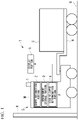
- the drive control system S has a distance sensor 1 (measurement means or measurement portion), a shape recognition portion 2, an arrangement storage portion 3, and a load collapse determination portion 4 (load collapse determination means) and a display portion 5. Furthermore, the shape recognition portion 2, the arrangement storage portion 3, and the load collapse determination portion 4 are configured as one function of an arithmetic device P.
- the arithmetic device P is a computer configured with a central processing unit (CPU), memory such as random access memory (RAM) and read only memory (ROM), and an input/output device that exchanges signals with an external device, and the like.
- the arithmetic device P there is an electric control unit (ECU) mounted on the transportation vehicle T to control an internal combustion engine, an electric motor, a transmission, and the like, or a combination thereof. Therefore, as an algorithm executed by the computer or the ECU which is an example thereof, the functions of the shape recognition portion 2, the posture storage portion 3, and the load collapse determination portion 4 may be implemented. Furthermore, the shape recognition portion 2, the arrangement storage portion 3, and the load collapse determination portion 4 may each be a computer configured with a CPU, memory such as RAM and ROM, an input/output device that exchanges signals with an external device, and the like. In this case, the functions of the shape recognition portion 2, the arrangement storage portion 3, and the load collapse determination portion 4 may be implemented as an algorithm executed by each computer provided in the shape recognition portion 2, the arrangement storage portion 3, and the load collapse determination portion 4.
- ECU electric control unit
- the distance sensor 1 is provided at an upper part of the trailer head H of the transportation vehicle T (vehicle), for example, as shown in Figs. 1 and 2 .
- the distance sensor 1 is a device capable of detecting a distance to a target by irradiating the target with a pulsed laser light and measuring a time period until the light reflected from the target reaches the distance sensor 1.
- the distance sensor 1 mounted at a front side in a traveling direction can scan a region including the front and the rear of the transportation vehicle T, and can also detect an obstacle R by measuring a distance to the obstacle R that may exist around the transportation vehicle T including the front of the transportation vehicle T and that can obstruct the operation of the transportation vehicle T.
- the distance sensor 1 is, for example, a two-dimensional or three-dimensional laser range finder (LRF) or a two-dimensional or three-dimensional light detection and ranging or laser imaging detection and ranging (LIDAR).
- LRF laser range finder
- LIDAR laser imaging detection and ranging
- the data of a sensor used for simultaneous localization and mapping (SLAM) may be applied to the distance sensor 1.
- An object for which the distance sensor 1 measures a distance may be collectively referred to as a surrounding body. That is, the surrounding body includes the obstacle R, the transportation target C, the loading platform N, a ground G (road surface), and the like.
- the shape recognition portion 2 identifies an outer shape from a data point cloud based on measurement data acquired from the distance sensor 1.
- the measurement data is, for example, data showing a distance to a target measured by the distance sensor 1.
- a plurality of measurement points which are points on a surface of the target whose distance to the distance sensor 1 is measured by irradiating the surface of the target with pulsed laser light are displayed as points on the target.
- This plurality of points is referred to a data point cloud.
- the shape recognition portion 2 groups (makes a set of) continuous measurement points having close heights based on the acquired data point cloud to identify the measurement points as an outer shape of a body.
- the shape recognition portion 2 can detect not only the shape of the transportation target C but also an outer shape of a body that can be the obstacle R in a traveling direction. Therefore, the shape recognition portion 2 also serves as an obstacle detection sensor. Furthermore, the distance sensor 1 and the arithmetic device P are electrically and/or electronically connected to exchange signals with each other.
- the arrangement storage portion 3 stores a group of measurement points identified by the shape recognition portion 2 by time (by frame). In addition, the arrangement storage portion 3 also stores the outer shape of the body in the traveling direction in the same manner.
- the load collapse determination portion 4 determines whether the shape of the group is linear. Then, the load collapse determination portion 4 uses the group of linear measurement points as a determination reference for the arrangement of the transportation target C to determine a load collapse. That is, the load collapse determination portion 4 compares the arrangement of a group in a current frame with the arrangement of a group of measurement points having close height positions in an immediately previous frame (previous or past frame) using the group of linear measurement points to determine that there is a load collapse in a case where a difference in arrangement is a threshold value or greater.
- the display portion 5 is, for example, a monitor provided in central control equipment or the like that manages the driving of an unmanned transportation vehicle and displays a warning or the like in a case where it is determined as a load collapse. Furthermore, in a case where an operator is present in the transportation vehicle T, a warning may be displayed on a windshield of a driver's seat, a vehicle-mounted monitor, or the like.
- the central control equipment or the like refers to an equipment that allows an observer to constantly monitor, for example, driving status such as the presence or absence of a load collapse in an unmanned transportation vehicle. As necessary, an instruction such as stop may be transmitted from the central control equipment or the like to the unmanned transportation vehicle. In addition, the central control equipment or the like may monitor a plurality of unmanned transportation vehicles at the same time.
- the distance sensor 1 measures a distance to a point cloud of the measurement points of the transportation target C (step S1).
- the shape recognition portion 2 compares the heights of the acquired point clouds in a vertical direction, and groups the measurement points having close distances and close heights of the point clouds (i.e., in which a difference in distance and height is a predetermined value or less) (step S2).
- the arrangement storage portion 3 stores the measurement points grouped by the shape recognition portion 2 (step S3).
- the load collapse determination portion 4 determines whether the group in a current frame is linear (step S4). In the step S4, in a case where the determination is NO, that is, in a case where the group is not linear, it is not determined as a load collapse.
- the load collapse determination portion 4 determines whether a difference between the arrangement of a group (G1) of measurement points in a current frame, and the arrangement of a group (G2) of measurement points whose position is close to the group (G1) of the measurement points in the current frame in an immediately previous frame stored in the arrangement storage portion 3 is a threshold value or greater (step S5).
- the step S5 in a case where the determination is YES, that is, in a case where a difference in arrangement is the threshold value or greater, it is determined that a load collapse has occurred, and a warning is displayed on the display portion 5 (step S6).
- the determination is NO in the step S5
- the difference in arrangement is less than the threshold value
- a connection angle between the trailer head H and the transportation target C changes.
- a change in the arrangement of the transportation target C can be detected by acquiring a value of the connection angle between the trailer head H and the transportation target C from a sensor (e.g., angle sensor) provided on the transportation vehicle T to measure the connection angle, and correcting measurement data acquired by the distance sensor 1 by the connection angle.
- a sensor e.g., angle sensor
- the arrangement of the transportation target C can be detected using the distance sensor 1 that also serves as an obstacle detection sensor to determine a load collapse by the load collapse determination portion 4. Accordingly, a load collapse of the transportation target C can be determined with a simple configuration without providing a load collapse detection sensor separately from the obstacle detection sensor.
- the load collapse of the transportation target C can be determined with a simple configuration, thereby suppressing a processing capacity of the arithmetic device P mounted on the drive control system S to a low level and increasing a processing speed of the arithmetic device P. Therefore, it is possible to contribute to the implementation of autonomous driving of the transportation vehicle T that is transporting the transportation target C, thereby improving computer-related technology.
- a group of a plurality of continuous linear measurement points in an outer shape of the transportation target C is used as a reference for the arrangement of the transportation target C. Accordingly, comparison between frames can be easily performed to facilitate the determination of a load collapse.
- the distance sensor 1 since the distance sensor 1 is mounted at an upper part of the transportation vehicle T, a blind spot can be reduced in both front and rear of a traveling direction. Therefore, the obstacle R in front of the traveling direction and the transportation target C in rear of the traveling direction can be measured.
- a drive control system of the present disclosure it is possible to determine a load collapse of a transportation target with a simple configuration based on measurement data of a measurement portion that detects an obstacle by a load collapse determination portion.
Landscapes
- Engineering & Computer Science (AREA)
- Physics & Mathematics (AREA)
- General Physics & Mathematics (AREA)
- Electromagnetism (AREA)
- Mechanical Engineering (AREA)
- Remote Sensing (AREA)
- Radar, Positioning & Navigation (AREA)
- Computer Networks & Wireless Communication (AREA)
- Transportation (AREA)
- Automation & Control Theory (AREA)
- Mathematical Physics (AREA)
- Human Computer Interaction (AREA)
- Traffic Control Systems (AREA)
- Control Of Position, Course, Altitude, Or Attitude Of Moving Bodies (AREA)
Abstract
Description
- The present disclosure relates to a drive control system.
- Priority is claimed on
Japanese Patent Application No. 2019-118572, filed June 26, 2019 -
Patent Document 1 discloses a transport vehicle that moves in a state where a load (transportation target) is placed thereon. In such a transport vehicle, in order to prevent and detect the fall of the load, a load collapse detection sensor is used to detect the collapse of the load placed on a placement section. The load collapse detection sensor inPatent Document 1 is a rod-shaped contact sensor, and is disposed in contact with the load. In addition, the transport vehicle ofPatent Document 1 is provided with an obstacle sensor that detects an obstacle appearing around the transport vehicle, in addition to the load collapse detection sensor.Patent Document 2 discloses an autonomous mobile unmanned transportation car including a tray presence/absence sensor that detects the presence or absence of a load (tray) in addition to an ultrasonic sensor corresponding to the obstacle sensor ofPatent Document 1. -
- [Patent Document 1]
Japanese Unexamined Patent Application, First Publication No. 2012-158445 - [Patent Document 2]
Japanese Unexamined Patent Application, First Publication No. 2014-186693 - In recent years, autonomous driving using a large transportation vehicle such as a truck has been considered. In such an autonomous driving vehicle, a load collapse cannot be recognized since a driver is not present in the vehicle. Therefore, it is needed to automatically detect the load collapse. However, the configuration of the transport vehicle shown in
Patent Document 1 is complicated since it is needed to newly provide a load collapse detection sensor in addition to the obstacle sensor. The same applies to - The present disclosure has been made in view of the above circumstances, and an object of the present disclosure is to determine a load collapse in a transportation vehicle with a simple configuration.
- A drive control system according to a first aspect of the present disclosure includes a measurement portion configured to detect an obstacle in a transportation vehicle, and a load collapse determination portion configured to acquire an arrangement of a transportation target loaded on the transportation vehicle based on measurement data of the measurement portion to determine a load collapse of the transportation target based on a change in the arrangement over time.
- For the drive control system according to a second aspect of the present disclosure, in the first aspect, the measurement portion is mounted on the transportation vehicle and performs scanning with laser light to measure a distance between the transportation vehicle and a surrounding body.
- For the drive control system according to a third aspect of the present disclosure, in the second aspect, the load collapse determination portion uses a set of a plurality of continuous linear measurement points in an outer shape of the transportation target as a reference for the arrangement of the transportation target.
- For the drive control system according to a fourth aspect of the present disclosure, in any one of the first to third aspects, the measurement portion is provided at an upper part of the transportation vehicle.
- For the drive control system according to a fifth aspect of the present disclosure, in any one of the first to third aspects, the measurement portion is provided at each of left and right ends of the transportation vehicle.
- According to the present disclosure, it is possible to determine a load collapse of a transportation target with a simple configuration by a load collapse determination portion based on measurement data of a measurement portion that detects an obstacle.
-
-
Fig. 1 is a schematic diagram including a drive control system according to an embodiment of the present disclosure. -
Fig. 2 is a schematic diagram showing a mounting position of a distance sensor in a transportation vehicle. -
Fig. 3 is a flowchart illustrating a load collapse determination procedure of a drive control system according to an embodiment of the present disclosure. -
Fig. 4 is a schematic diagram showing a modified example of a mounting position of a distance sensor in a transportation vehicle. - Hereinafter, a drive control system S according to an embodiment of the present disclosure will be described with reference to the drawings.
- The drive control system S (drive control system) according to an embodiment of the present disclosure is a system that transports a transportation target (e.g., transportation target C) to a destination place or supports transportation thereof. The drive control system S of the present disclosure is a system that performs autonomous driving of the transportation vehicle T that transports the transportation target C. Furthermore, the transportation vehicle T has a structure including a trailer head H and a loading platform N connected to the trailer head H. The transportation vehicle T may be unmanned or manned, but in the following description, it is assumed that the transportation vehicle T is an unmanned transportation vehicle. The transportation target C is loaded on the loading platform N.
- As shown in
Fig. 1 , the drive control system S according to the present embodiment has a distance sensor 1 (measurement means or measurement portion), ashape recognition portion 2, anarrangement storage portion 3, and a load collapse determination portion 4 (load collapse determination means) and adisplay portion 5. Furthermore, theshape recognition portion 2, thearrangement storage portion 3, and the loadcollapse determination portion 4 are configured as one function of an arithmetic device P. The arithmetic device P is a computer configured with a central processing unit (CPU), memory such as random access memory (RAM) and read only memory (ROM), and an input/output device that exchanges signals with an external device, and the like. As an example of the arithmetic device P, there is an electric control unit (ECU) mounted on the transportation vehicle T to control an internal combustion engine, an electric motor, a transmission, and the like, or a combination thereof. Therefore, as an algorithm executed by the computer or the ECU which is an example thereof, the functions of theshape recognition portion 2, theposture storage portion 3, and the loadcollapse determination portion 4 may be implemented. Furthermore, theshape recognition portion 2, thearrangement storage portion 3, and the loadcollapse determination portion 4 may each be a computer configured with a CPU, memory such as RAM and ROM, an input/output device that exchanges signals with an external device, and the like. In this case, the functions of theshape recognition portion 2, thearrangement storage portion 3, and the loadcollapse determination portion 4 may be implemented as an algorithm executed by each computer provided in theshape recognition portion 2, thearrangement storage portion 3, and the loadcollapse determination portion 4. - The
distance sensor 1 is provided at an upper part of the trailer head H of the transportation vehicle T (vehicle), for example, as shown inFigs. 1 and2 . Thedistance sensor 1 is a device capable of detecting a distance to a target by irradiating the target with a pulsed laser light and measuring a time period until the light reflected from the target reaches thedistance sensor 1. Furthermore, thedistance sensor 1 mounted at a front side in a traveling direction can scan a region including the front and the rear of the transportation vehicle T, and can also detect an obstacle R by measuring a distance to the obstacle R that may exist around the transportation vehicle T including the front of the transportation vehicle T and that can obstruct the operation of the transportation vehicle T. It is assumed that the obstacle R is, for example, a utility pole, a wall of tunnel, a railroad crossing or parking lot barrier, a median strip, another parked vehicle, another driving vehicle, a guard temporarily provided on a road surface under construction, and the like. Thedistance sensor 1 is, for example, a two-dimensional or three-dimensional laser range finder (LRF) or a two-dimensional or three-dimensional light detection and ranging or laser imaging detection and ranging (LIDAR). In addition, the data of a sensor used for simultaneous localization and mapping (SLAM) may be applied to thedistance sensor 1. An object for which thedistance sensor 1 measures a distance may be collectively referred to as a surrounding body. That is, the surrounding body includes the obstacle R, the transportation target C, the loading platform N, a ground G (road surface), and the like. - The
shape recognition portion 2 identifies an outer shape from a data point cloud based on measurement data acquired from thedistance sensor 1. Here, the measurement data is, for example, data showing a distance to a target measured by thedistance sensor 1. When this data is visualized, a plurality of measurement points, which are points on a surface of the target whose distance to thedistance sensor 1 is measured by irradiating the surface of the target with pulsed laser light are displayed as points on the target. This plurality of points is referred to a data point cloud. Theshape recognition portion 2 groups (makes a set of) continuous measurement points having close heights based on the acquired data point cloud to identify the measurement points as an outer shape of a body. Furthermore, theshape recognition portion 2 can detect not only the shape of the transportation target C but also an outer shape of a body that can be the obstacle R in a traveling direction. Therefore, theshape recognition portion 2 also serves as an obstacle detection sensor. Furthermore, thedistance sensor 1 and the arithmetic device P are electrically and/or electronically connected to exchange signals with each other. - The
arrangement storage portion 3 stores a group of measurement points identified by theshape recognition portion 2 by time (by frame). In addition, thearrangement storage portion 3 also stores the outer shape of the body in the traveling direction in the same manner. - In the group of measurement points stored in the
arrangement storage portion 3, the loadcollapse determination portion 4 determines whether the shape of the group is linear. Then, the loadcollapse determination portion 4 uses the group of linear measurement points as a determination reference for the arrangement of the transportation target C to determine a load collapse. That is, the loadcollapse determination portion 4 compares the arrangement of a group in a current frame with the arrangement of a group of measurement points having close height positions in an immediately previous frame (previous or past frame) using the group of linear measurement points to determine that there is a load collapse in a case where a difference in arrangement is a threshold value or greater. - The
display portion 5 is, for example, a monitor provided in central control equipment or the like that manages the driving of an unmanned transportation vehicle and displays a warning or the like in a case where it is determined as a load collapse. Furthermore, in a case where an operator is present in the transportation vehicle T, a warning may be displayed on a windshield of a driver's seat, a vehicle-mounted monitor, or the like. Furthermore, the central control equipment or the like refers to an equipment that allows an observer to constantly monitor, for example, driving status such as the presence or absence of a load collapse in an unmanned transportation vehicle. As necessary, an instruction such as stop may be transmitted from the central control equipment or the like to the unmanned transportation vehicle. In addition, the central control equipment or the like may monitor a plurality of unmanned transportation vehicles at the same time. - A flow of the load collapse determination in the drive control system S will be described with reference to
Fig. 3 . - The
distance sensor 1 measures a distance to a point cloud of the measurement points of the transportation target C (step S1). - Then, the
shape recognition portion 2 compares the heights of the acquired point clouds in a vertical direction, and groups the measurement points having close distances and close heights of the point clouds (i.e., in which a difference in distance and height is a predetermined value or less) (step S2). - Then, the
arrangement storage portion 3 stores the measurement points grouped by the shape recognition portion 2 (step S3). Moreover, the loadcollapse determination portion 4 determines whether the group in a current frame is linear (step S4). In the step S4, in a case where the determination is NO, that is, in a case where the group is not linear, it is not determined as a load collapse. - In the step S4, in a case where the determination is YES, that is, in a case where the group is linear, the load
collapse determination portion 4 determines whether a difference between the arrangement of a group (G1) of measurement points in a current frame, and the arrangement of a group (G2) of measurement points whose position is close to the group (G1) of the measurement points in the current frame in an immediately previous frame stored in thearrangement storage portion 3 is a threshold value or greater (step S5). In the step S5, in a case where the determination is YES, that is, in a case where a difference in arrangement is the threshold value or greater, it is determined that a load collapse has occurred, and a warning is displayed on the display portion 5 (step S6). In addition, in a case where the determination is NO in the step S5, that is, in a case where the difference in arrangement is less than the threshold value, it is determined that a load collapse has not occurred. - Furthermore, in a case where the transportation vehicle T turns or the like, there may be a case where a connection angle between the trailer head H and the transportation target C changes. In such a case, a change in the arrangement of the transportation target C can be detected by acquiring a value of the connection angle between the trailer head H and the transportation target C from a sensor (e.g., angle sensor) provided on the transportation vehicle T to measure the connection angle, and correcting measurement data acquired by the
distance sensor 1 by the connection angle. - According to the present embodiment, the arrangement of the transportation target C can be detected using the
distance sensor 1 that also serves as an obstacle detection sensor to determine a load collapse by the loadcollapse determination portion 4. Accordingly, a load collapse of the transportation target C can be determined with a simple configuration without providing a load collapse detection sensor separately from the obstacle detection sensor. The load collapse of the transportation target C can be determined with a simple configuration, thereby suppressing a processing capacity of the arithmetic device P mounted on the drive control system S to a low level and increasing a processing speed of the arithmetic device P. Therefore, it is possible to contribute to the implementation of autonomous driving of the transportation vehicle T that is transporting the transportation target C, thereby improving computer-related technology. - According to the present embodiment, a group of a plurality of continuous linear measurement points in an outer shape of the transportation target C is used as a reference for the arrangement of the transportation target C. Accordingly, comparison between frames can be easily performed to facilitate the determination of a load collapse.
- In addition, according to the present embodiment, since the
distance sensor 1 is mounted at an upper part of the transportation vehicle T, a blind spot can be reduced in both front and rear of a traveling direction. Therefore, the obstacle R in front of the traveling direction and the transportation target C in rear of the traveling direction can be measured. - Furthermore, the present disclosure is not limited to the above embodiment, and for example, the following modifications are considered.
- (1) In the above embodiment, in a case where a load collapse occurs, a warning is displayed on the
display portion 5, but the present disclosure is not limited thereto. For example, in a case where a load collapse occurs, a process of stopping the driving of the transportation vehicle T from the central control equipment or the like may be performed. This process may be performed artificially by an observer in the central control equipment or the like, or may be automatically performed by the central control equipment or the like. - (2) In the above embodiment, a distance is measured using LiDAR as a measurement portion, but the present disclosure is not limited thereto. For example, an omnidirectional camera, a wide-angle radar, or the like may be used as the measurement portion.
- (3) In addition, a plurality of
distance sensors 1 may be provided. For example, as shown inFig. 4 , thedistance sensors 1 may be provided at two places at left and right ends of a trailer head H' in a direction orthogonal to a traveling direction (left-right direction) of a transportation vehicle T'. In this case, measurement points measured by thedistance sensors 1 at the two places can be compared to detect the arrangement of the transportation target C. In this case, not only a measurement range of thedistance sensors 1 can be widened by reducing a blind spot of thedistance sensors 1, but also the measurement points measured by thedistance sensors 1 at two places can be compared to detect the arrangement of the transportation target C, thereby more widely and accurately detecting the arrangement of the transportation target C. - (4) In the above embodiment, the drive control system S is a system that supports autonomous driving of an unmanned transportation vehicle, but the present disclosure is not limited thereto. For example, the drive control system S may be a system that provides driving support information to a driver of a manned transportation vehicle. In this case, load collapse warning information is displayed on a monitor that can be visually recognized by the driver of the transportation vehicle T or on a windshield.
- (5) Furthermore, in the above embodiment, it is determined that a load collapse occurs, but a state where the transportation target C is losing its balance can be detected by reducing a threshold value of change in the arrangement of the transportation target C. Thus, the occurrence of a load collapse of the transportation target C can be predicted or it is possible to issue a warning at a stage when a deviation, which may grow into a load collapse, occurs in the future.
- (6) In the above embodiment, the warning information of a load collapse is displayed on the display portion, but the present disclosure is not limited thereto. The warning information of the load collapse may be notified as voice to a manager of the unmanned transportation vehicle or the driver of the manned transportation vehicle.
- (7) In the above embodiment, as shown in
Fig. 2 , it is assumed that the number of transportation targets C is one, but the present disclosure is not limited thereto, and a load collapse can be determined even when there are a plurality of transportation targets C. - According to a drive control system of the present disclosure, it is possible to determine a load collapse of a transportation target with a simple configuration based on measurement data of a measurement portion that detects an obstacle by a load collapse determination portion.
-
- 1: Distance sensor
- 2: Shape recognition portion
- 3: Arrangement storage portion
- 4: Load Collapse Determination portion
- 5: Display portion
- C: Transportation target
- S: Drive control system
Claims (5)
- A drive control system comprising:a measurement portion configured to detect an obstacle in a transportation vehicle; anda load collapse determination portion configured to acquire an arrangement of a transportation target loaded on the transportation vehicle based on measurement data of the measurement portion to determine a load collapse of the transportation target based on a change in the arrangement over time.
- The drive control system according to Claim 1, wherein the measurement portion is mounted on the transportation vehicle and performs scanning with laser light to measure a distance between the transportation vehicle and a surrounding body.
- The drive control system according to Claim 2, wherein the load collapse determination portion uses a set of a plurality of continuous linear measurement points in an outer shape of the transportation target as a reference for the arrangement of the transportation target.
- The drive control system according to any one of Claims 1 to 3, wherein the measurement portion is provided at an upper part of the transportation vehicle.
- The drive control system according to any one of Claims 1 to 3, wherein the measurement portion is provided at each of left and right ends of the transportation vehicle.
Applications Claiming Priority (2)
| Application Number | Priority Date | Filing Date | Title |
|---|---|---|---|
| JP2019118572 | 2019-06-26 | ||
| PCT/JP2020/022659 WO2020261973A1 (en) | 2019-06-26 | 2020-06-09 | Drive control system |
Publications (2)
| Publication Number | Publication Date |
|---|---|
| EP3992031A1 true EP3992031A1 (en) | 2022-05-04 |
| EP3992031A4 EP3992031A4 (en) | 2023-07-19 |
Family
ID=74060964
Family Applications (1)
| Application Number | Title | Priority Date | Filing Date |
|---|---|---|---|
| EP20833690.9A Withdrawn EP3992031A4 (en) | 2019-06-26 | 2020-06-09 | DRIVE CONTROL SYSTEM |
Country Status (6)
| Country | Link |
|---|---|
| US (1) | US12115997B2 (en) |
| EP (1) | EP3992031A4 (en) |
| JP (1) | JP7180777B2 (en) |
| KR (1) | KR102587696B1 (en) |
| CN (1) | CN114072314B (en) |
| WO (1) | WO2020261973A1 (en) |
Cited By (1)
| Publication number | Priority date | Publication date | Assignee | Title |
|---|---|---|---|---|
| WO2024058719A1 (en) * | 2022-09-14 | 2024-03-21 | Venti Technologies | Container misalignment detection system and methods for autonomous vehicles |
Family Cites Families (37)
| Publication number | Priority date | Publication date | Assignee | Title |
|---|---|---|---|---|
| JP3299125B2 (en) * | 1996-09-30 | 2002-07-08 | 日野自動車株式会社 | Load collapse alarm |
| JP4330050B2 (en) | 1999-08-27 | 2009-09-09 | 東急車輛製造株式会社 | Pallet carrier |
| JP2005018472A (en) | 2003-06-26 | 2005-01-20 | Nec Mobiling Ltd | Cargo vehicle collapse monitoring system and method |
| JP5165503B2 (en) * | 2008-08-29 | 2013-03-21 | 全国農業協同組合連合会 | Load monitoring method and load monitoring system therefor |
| JP5429204B2 (en) | 2011-02-01 | 2014-02-26 | 村田機械株式会社 | Transport vehicle |
| JP2013035399A (en) | 2011-08-08 | 2013-02-21 | Toshiba Alpine Automotive Technology Corp | Luggage compartment monitoring device |
| JP5908333B2 (en) * | 2012-04-27 | 2016-04-26 | 株式会社日立製作所 | forklift |
| JP6136434B2 (en) | 2013-03-25 | 2017-05-31 | 村田機械株式会社 | Autonomous automatic guided vehicle |
| CN103273880A (en) | 2013-05-23 | 2013-09-04 | 无锡伊佩克科技有限公司 | System capable of preventing truck goods from dropping |
| CN105611981B (en) * | 2014-07-30 | 2018-04-03 | 株式会社小松制作所 | The control method of carrying vehicle and carrying vehicle |
| JP2016081159A (en) | 2014-10-14 | 2016-05-16 | トヨタ自動車株式会社 | Moving body |
| US9880253B2 (en) * | 2014-10-28 | 2018-01-30 | Nissan North America, Inc. | Vehicle object monitoring system |
| KR102326062B1 (en) * | 2014-11-12 | 2021-11-12 | 현대모비스 주식회사 | System and method for avoiding obstacle for autonomous vehicle |
| DE102014226108A1 (en) | 2014-12-16 | 2016-06-16 | Volkswagen Aktiengesellschaft | Charge monitoring in the motor vehicle |
| US9944213B2 (en) * | 2015-05-13 | 2018-04-17 | Stratom, Inc. | Robotic cargo system |
| JP6741402B2 (en) | 2015-06-18 | 2020-08-19 | 日野自動車株式会社 | Information providing device, vehicle, and information providing method |
| US20160368336A1 (en) | 2015-06-19 | 2016-12-22 | Paccar Inc | Use of laser scanner for autonomous truck operation |
| JP6507894B2 (en) * | 2015-07-08 | 2019-05-08 | 株式会社豊田自動織機 | Travel control method at unloading in unmanned forklift and travel control device at unloading |
| US9958872B2 (en) * | 2016-06-06 | 2018-05-01 | International Business Machines Corporation | Cargo-based vehicle control |
| US10346797B2 (en) * | 2016-09-26 | 2019-07-09 | Cybernet Systems, Inc. | Path and load localization and operations supporting automated warehousing using robotic forklifts or other material handling vehicles |
| US11048251B2 (en) | 2017-08-16 | 2021-06-29 | Uatc, Llc | Configuring motion planning for a self-driving tractor unit |
| JP6794341B2 (en) | 2017-12-28 | 2020-12-02 | ユニ・チャーム株式会社 | Absorbent article |
| US10720070B2 (en) * | 2018-01-03 | 2020-07-21 | Qualcomm Incorporated | Adjustable object avoidance proximity threshold of a robotic vehicle based on presence of detected payload(s) |
| US11041956B2 (en) * | 2018-05-24 | 2021-06-22 | Toyota Motor Engineering & Manufacturing North America, Inc. | Lidar module and portable lidar scanner unit |
| WO2020010047A1 (en) * | 2018-07-05 | 2020-01-09 | Brain Corporation | Systems and methods for operating autonomous tug robots |
| WO2020089170A1 (en) * | 2018-10-29 | 2020-05-07 | Fq Ip Ab | Mechanical coupling of vehicles |
| US11770677B1 (en) * | 2019-01-08 | 2023-09-26 | Spirited Eagle Enterprises, LLC | Enhanced safety systems and method for transportation vehicles |
| SG11202110876VA (en) * | 2019-04-03 | 2021-11-29 | Ihi Corp | Weight estimation system |
| US11429113B2 (en) * | 2019-08-08 | 2022-08-30 | Lg Electronics Inc. | Serving system using robot and operation method thereof |
| US11062582B1 (en) * | 2020-02-07 | 2021-07-13 | Ford Global Technologies, Llc | Pick-up cargo bed capacitive sensor systems and methods |
| US20220035684A1 (en) * | 2020-08-03 | 2022-02-03 | Nvidia Corporation | Dynamic load balancing of operations for real-time deep learning analytics |
| US11787397B2 (en) * | 2021-01-20 | 2023-10-17 | Ford Global Technologies, Llc | Vehicle cargo management systems |
| US20220379792A1 (en) * | 2021-05-25 | 2022-12-01 | Stratom, Inc. | Cargo transport system |
| WO2023064520A1 (en) * | 2021-10-14 | 2023-04-20 | Tusimple, Inc. | Systems and methods for operating an autonomous vehicle |
| US12005886B2 (en) * | 2022-04-22 | 2024-06-11 | Ford Global Technologies, Llc | Methods and apparatus to control stability of a vehicle and trailer |
| US12157485B2 (en) * | 2022-10-12 | 2024-12-03 | Toyota Motor Engineering & Manufacturing North America, Inc. | Truck bed hauling warning system for shifting loads |
| WO2024102846A1 (en) * | 2022-11-08 | 2024-05-16 | Seegrid Corporation | System and method for definition of a zone of dynamic behavior with a continuum of possible actions and locations within the same |
-
2020
- 2020-06-09 US US17/619,748 patent/US12115997B2/en active Active
- 2020-06-09 WO PCT/JP2020/022659 patent/WO2020261973A1/en not_active Ceased
- 2020-06-09 EP EP20833690.9A patent/EP3992031A4/en not_active Withdrawn
- 2020-06-09 JP JP2021528106A patent/JP7180777B2/en active Active
- 2020-06-09 KR KR1020217040521A patent/KR102587696B1/en active Active
- 2020-06-09 CN CN202080045695.9A patent/CN114072314B/en active Active
Cited By (1)
| Publication number | Priority date | Publication date | Assignee | Title |
|---|---|---|---|---|
| WO2024058719A1 (en) * | 2022-09-14 | 2024-03-21 | Venti Technologies | Container misalignment detection system and methods for autonomous vehicles |
Also Published As
| Publication number | Publication date |
|---|---|
| KR102587696B1 (en) | 2023-10-10 |
| KR20220006622A (en) | 2022-01-17 |
| EP3992031A4 (en) | 2023-07-19 |
| US20220355806A1 (en) | 2022-11-10 |
| US12115997B2 (en) | 2024-10-15 |
| CN114072314B (en) | 2024-06-11 |
| CN114072314A (en) | 2022-02-18 |
| JPWO2020261973A1 (en) | 2020-12-30 |
| JP7180777B2 (en) | 2022-11-30 |
| WO2020261973A1 (en) | 2020-12-30 |
Similar Documents
| Publication | Publication Date | Title |
|---|---|---|
| US11086333B2 (en) | Sensor array for an autonomously operated utility vehicle and method for surround-view image acquisition | |
| US10260889B2 (en) | Position estimation device and position estimation method | |
| US12103527B2 (en) | Weight estimation system | |
| CN105984464B (en) | Controller of vehicle | |
| US10442465B2 (en) | Parking assistance device and vehicle provided with such a device | |
| KR102937581B1 (en) | A method for evaluating the effect of objects surrounding a vehicle on its operation. | |
| US10539963B2 (en) | Device for determining a space in which a vehicle can drive, corresponding method, and vehicle | |
| WO2019183981A1 (en) | Vehicle and method for avoiding a collision of a vehicle with one or more obstacles | |
| JP2019192024A (en) | Work vehicle | |
| US10559206B2 (en) | Mobile body spatial information calculation apparatus and collision avoidance system | |
| CN113329927A (en) | Laser radar based trailer tracking | |
| US11709260B2 (en) | Data driven resolution function derivation | |
| JP6645074B2 (en) | Obstacle detection system | |
| US12115997B2 (en) | Drive control system | |
| CN117232427A (en) | System and method for dynamically determining vehicle and trailer dimensions from shadow outlines | |
| US11993274B2 (en) | Monitoring of on-board vehicle image capturing device functionality compliance | |
| JP2020067702A (en) | Attitude detection device and transportation system | |
| KR20240026422A (en) | A method for controlling drive-through and an apparatus for controlling drive-through | |
| US20240303850A1 (en) | Method for determining the height of a trailer of a motor vehicle and electronic computing device | |
| US20260008459A1 (en) | Method for free space extension for autonomous driving | |
| CN120863619A (en) | Control method of vehicle and vehicle |
Legal Events
| Date | Code | Title | Description |
|---|---|---|---|
| STAA | Information on the status of an ep patent application or granted ep patent |
Free format text: STATUS: THE INTERNATIONAL PUBLICATION HAS BEEN MADE |
|
| PUAI | Public reference made under article 153(3) epc to a published international application that has entered the european phase |
Free format text: ORIGINAL CODE: 0009012 |
|
| STAA | Information on the status of an ep patent application or granted ep patent |
Free format text: STATUS: REQUEST FOR EXAMINATION WAS MADE |
|
| 17P | Request for examination filed |
Effective date: 20211216 |
|
| AK | Designated contracting states |
Kind code of ref document: A1 Designated state(s): AL AT BE BG CH CY CZ DE DK EE ES FI FR GB GR HR HU IE IS IT LI LT LU LV MC MK MT NL NO PL PT RO RS SE SI SK SM TR |
|
| DAV | Request for validation of the european patent (deleted) | ||
| DAX | Request for extension of the european patent (deleted) | ||
| REG | Reference to a national code |
Ref country code: DE Ref legal event code: R079 Free format text: PREVIOUS MAIN CLASS: B60P0009000000 Ipc: G01S0007480000 |
|
| A4 | Supplementary search report drawn up and despatched |
Effective date: 20230619 |
|
| RIC1 | Information provided on ipc code assigned before grant |
Ipc: B60P 7/08 20060101ALN20230613BHEP Ipc: G01S 17/931 20200101ALI20230613BHEP Ipc: G01S 17/88 20060101ALI20230613BHEP Ipc: G01S 17/50 20060101ALI20230613BHEP Ipc: G01S 17/42 20060101ALI20230613BHEP Ipc: G01S 7/48 20060101AFI20230613BHEP |
|
| REG | Reference to a national code |
Ref country code: DE Ref legal event code: R079 Free format text: PREVIOUS MAIN CLASS: G01S0007480000 Ipc: G01S0017931000 |
|
| GRAP | Despatch of communication of intention to grant a patent |
Free format text: ORIGINAL CODE: EPIDOSNIGR1 |
|
| STAA | Information on the status of an ep patent application or granted ep patent |
Free format text: STATUS: GRANT OF PATENT IS INTENDED |
|
| RIC1 | Information provided on ipc code assigned before grant |
Ipc: B60P 7/08 20060101ALN20250303BHEP Ipc: G01S 17/88 20060101ALI20250303BHEP Ipc: G01S 17/50 20060101ALI20250303BHEP Ipc: G01S 17/42 20060101ALI20250303BHEP Ipc: G01S 7/48 20060101ALI20250303BHEP Ipc: G01S 17/931 20200101AFI20250303BHEP |
|
| INTG | Intention to grant announced |
Effective date: 20250314 |
|
| STAA | Information on the status of an ep patent application or granted ep patent |
Free format text: STATUS: THE APPLICATION HAS BEEN WITHDRAWN |
|
| 18W | Application withdrawn |
Effective date: 20250606 |