EP3991544A1 - Work vehicle - Google Patents
Work vehicle Download PDFInfo
- Publication number
- EP3991544A1 EP3991544A1 EP20832439.2A EP20832439A EP3991544A1 EP 3991544 A1 EP3991544 A1 EP 3991544A1 EP 20832439 A EP20832439 A EP 20832439A EP 3991544 A1 EP3991544 A1 EP 3991544A1
- Authority
- EP
- European Patent Office
- Prior art keywords
- grass
- pasture
- pasture grass
- work vehicle
- water content
- Prior art date
- Legal status (The legal status is an assumption and is not a legal conclusion. Google has not performed a legal analysis and makes no representation as to the accuracy of the status listed.)
- Pending
Links
Images



Classifications
-
- A—HUMAN NECESSITIES
- A01—AGRICULTURE; FORESTRY; ANIMAL HUSBANDRY; HUNTING; TRAPPING; FISHING
- A01D—HARVESTING; MOWING
- A01D43/00—Mowers combined with apparatus performing additional operations while mowing
- A01D43/08—Mowers combined with apparatus performing additional operations while mowing with means for cutting up the mown crop, e.g. forage harvesters
- A01D43/085—Control or measuring arrangements specially adapted therefor
-
- A—HUMAN NECESSITIES
- A01—AGRICULTURE; FORESTRY; ANIMAL HUSBANDRY; HUNTING; TRAPPING; FISHING
- A01D—HARVESTING; MOWING
- A01D34/00—Mowers; Mowing apparatus of harvesters
- A01D34/006—Control or measuring arrangements
-
- A—HUMAN NECESSITIES
- A01—AGRICULTURE; FORESTRY; ANIMAL HUSBANDRY; HUNTING; TRAPPING; FISHING
- A01F—PROCESSING OF HARVESTED PRODUCE; HAY OR STRAW PRESSES; DEVICES FOR STORING AGRICULTURAL OR HORTICULTURAL PRODUCE
- A01F15/00—Baling presses for straw, hay or the like
- A01F15/08—Details
-
- A—HUMAN NECESSITIES
- A01—AGRICULTURE; FORESTRY; ANIMAL HUSBANDRY; HUNTING; TRAPPING; FISHING
- A01F—PROCESSING OF HARVESTED PRODUCE; HAY OR STRAW PRESSES; DEVICES FOR STORING AGRICULTURAL OR HORTICULTURAL PRODUCE
- A01F15/00—Baling presses for straw, hay or the like
- A01F15/08—Details
- A01F15/10—Feeding devices for the crop material e.g. precompression devices
-
- G—PHYSICS
- G01—MEASURING; TESTING
- G01N—INVESTIGATING OR ANALYSING MATERIALS BY DETERMINING THEIR CHEMICAL OR PHYSICAL PROPERTIES
- G01N21/00—Investigating or analysing materials by the use of optical means, i.e. using sub-millimetre waves, infrared, visible or ultraviolet light
- G01N21/17—Systems in which incident light is modified in accordance with the properties of the material investigated
- G01N21/25—Colour; Spectral properties, i.e. comparison of effect of material on the light at two or more different wavelengths or wavelength bands
- G01N21/31—Investigating relative effect of material at wavelengths characteristic of specific elements or molecules, e.g. atomic absorption spectrometry
- G01N21/35—Investigating relative effect of material at wavelengths characteristic of specific elements or molecules, e.g. atomic absorption spectrometry using infrared light
- G01N21/3554—Investigating relative effect of material at wavelengths characteristic of specific elements or molecules, e.g. atomic absorption spectrometry using infrared light for determining moisture content
-
- G—PHYSICS
- G01—MEASURING; TESTING
- G01N—INVESTIGATING OR ANALYSING MATERIALS BY DETERMINING THEIR CHEMICAL OR PHYSICAL PROPERTIES
- G01N21/00—Investigating or analysing materials by the use of optical means, i.e. using sub-millimetre waves, infrared, visible or ultraviolet light
- G01N21/17—Systems in which incident light is modified in accordance with the properties of the material investigated
- G01N21/25—Colour; Spectral properties, i.e. comparison of effect of material on the light at two or more different wavelengths or wavelength bands
- G01N21/31—Investigating relative effect of material at wavelengths characteristic of specific elements or molecules, e.g. atomic absorption spectrometry
- G01N21/35—Investigating relative effect of material at wavelengths characteristic of specific elements or molecules, e.g. atomic absorption spectrometry using infrared light
- G01N21/359—Investigating relative effect of material at wavelengths characteristic of specific elements or molecules, e.g. atomic absorption spectrometry using infrared light using near infrared light
-
- G—PHYSICS
- G01—MEASURING; TESTING
- G01N—INVESTIGATING OR ANALYSING MATERIALS BY DETERMINING THEIR CHEMICAL OR PHYSICAL PROPERTIES
- G01N21/00—Investigating or analysing materials by the use of optical means, i.e. using sub-millimetre waves, infrared, visible or ultraviolet light
- G01N21/84—Systems specially adapted for particular applications
- G01N2021/8466—Investigation of vegetal material, e.g. leaves, plants, fruits
-
- G—PHYSICS
- G01—MEASURING; TESTING
- G01N—INVESTIGATING OR ANALYSING MATERIALS BY DETERMINING THEIR CHEMICAL OR PHYSICAL PROPERTIES
- G01N21/00—Investigating or analysing materials by the use of optical means, i.e. using sub-millimetre waves, infrared, visible or ultraviolet light
- G01N21/17—Systems in which incident light is modified in accordance with the properties of the material investigated
- G01N21/47—Scattering, i.e. diffuse reflection
- G01N21/4738—Diffuse reflection, e.g. also for testing fluids, fibrous materials
-
- G—PHYSICS
- G01—MEASURING; TESTING
- G01N—INVESTIGATING OR ANALYSING MATERIALS BY DETERMINING THEIR CHEMICAL OR PHYSICAL PROPERTIES
- G01N2201/00—Features of devices classified in G01N21/00
- G01N2201/02—Mechanical
- G01N2201/021—Special mounting in general
- G01N2201/0216—Vehicle borne
Definitions
- the present invention relates to a work vehicle configured to determine quality of harvested pasture grass while traveling.
- Pasture grass are employed as forage for livestock.
- Pasture grass employed as such forage are stored in e.g, a silo after their mowing in a pasture land or sun-dried firstly in the pasture land and then formed into a cylindrical roll bale and collected as such,
- Pasture grass are generally subjected to butyric acid fermentation for their nutritional improvement.
- mold may be generated if the water content is too high.
- an additive such as formic acid or the like.
- management of the water content of pasture grass is important.
- Patent Document 1 for determination of water content of pasture grass, it has been conventionally practiced to determine the water content of pasture grass using e.g. a water content determination device on pasture grass left in the pasture land immediately after their harvest or pasture grass collected in the pasture land after their harvest.
- a water content determination device determines water content by irradiating light onto the pasture grass and then effecting a spectroscopic analysis of reflected light.
- Patent Document 1 Japanese Unexamined Patent Application Publication No 2018-185594 .
- the object of the present invention is to determine quality of pasture grass with high accuracy.
- a work vehicle relating to one embodiment of the present invention comprises a work vehicle configured to carry out work travel in a pasture land where harvested pasture grass are left, the work vehicle comprising a quality determination device configured to determine quality of pasture grass in a course of the work travel; wherein the quality determination device includes:
- the grass taking section takes in the pasture grass in the pasture land and packs them into the grass sending pipe (the grass sending tube).
- the grass sending pipe the grass sending tube.
- the quality determination instrument can carry out quality determination with irradiation of light to the pasture grass having reduced gaps, so that the quality of the pasture grass can be determined with high accuracy with effective suppression of diffused reflection of the light or the like.
- the pasture grass are stirred and mixed when being taken in by the grass taking section.
- the pasture grass having varied qualities will be fed in a mixed state to the quality determination instrument, so that determination of average quality of pasture grass left in the pasture land becomes possible.
- a work vehicle relating to one embodiment of the present invention includes a work vehicle including a harvesting section and configured to carry out harvesting travel in a pasture land, and a quality determination device configured to determine quality of pasture grass while carrying out work travel; wherein the quality determination device includes:
- the grass taking section takes in the pasture grass harvested by the harvesting section and feeds and packs them into the grass sending tube.
- the pasture grass present in a sparse state will be gradually compressed inside the grass sending tube.
- the quality determination instrument can carry out quality determination with irradiation of light to the pasture grass having reduced gaps, so that the quality of the pasture grass can be determined with high accuracy with effective suppression of diffused reflection of the light or the like.
- the portion of the pasture grass sent into the grass sending tube are discharged via the other end (a second end) of the grass sending tube to be merged with a portion of the pasture grass which was not sent into the grass sending tube.
- the pasture grass used in the quality determination are returned to the pasture grass which were not used for the determination, the pasture grass can be used without waste.
- the work vehicle further comprises a conveying path for collecting and conveying the pasture grass, wherein one end (first end) and the other end (second end) of the grass sending tube are connected to the conveying path, and the grass sending tube bypasses the conveying path.
- a harvester configured to collect pasture grass in a pasture land and stack them on a loader wagon, a truck, etc.
- a roll baler configured to collect pasture grass in a pasture land and to form them into a roll bale.
- Such work vehicles have a conveying path for conveying collected pasture grass.
- the quality determination device can be mounted on these work vehicles also, and the quality determination device can be incorporated in the conveying path included in the work vehicles. If the quality determination device is included in the conveying path, quality determination can be carried out on each batch of collected pasture grass. Further, as the quality determination of pasture grass can be carried out in the course or a work, if the quality is found inappropriate, it is possible to take such measure as adding an additive to the pasture grass or suspending the work. As a result, improvement of work efficiency is made possible.
- the grass taking section is configured to adjust an amount of pasture grass to be sent into the grass sending tube in proportion with a traveling speed of the work vehicle.
- the grass sending tube has a sectional area that is progressively decreased in at least a part of a section from the first end of the grass sending tube to an area where the quality determination device is disposed.
- the pasture grass By progressively decreasing the cross sectional area of the grass sending tube toward the quality determination device, the pasture grass can be compressed in an efficient manner. Thus, diffused reflection of the light or the like can be suppressed easily, and the quality of pasture grass can be determined with high accuracy.
- a work vehicle relating to one embodiment of the present invention comprises a work vehicle configured to carry out work travel in a pasture land, the work vehicle comprising a quality determination device configured to determine quality of pasture grass while carrying out the work travel; wherein the quality determination device includes:
- the grass pressing device presses the pasture grass to reduce the gaps therebetween, so the quality determination device can carry out the quality determination of the pasture grass under a dense state thereof. Further, since the grass pressing device is supported vertically movably, the grass pressing device can move up and down in response to repulsive force from the pasture grass. Therefore, there will not occur such inconvenience of the grass pressing device getting hooked with the grass to push out the pasture grass forwardly. Thus, the pasture grass can be pressed in an appropriate manner. For the reasons mentioned above, the work vehicle can determine the quality of pasture grass with high accuracy, with effective suppression of diffused reflection of the light or the like.
- the grass pressing device includes an elastic body configured to press down the grass pressing device.
- the grass pressing device can press the pasture grass more effectively by the elastic force of the elastic body, the diffused reflection of the light or the like can be suppressed to allow high accuracy determination of the quality of pasture grass.
- the supporting portion is vertically pivotally supported by a machine body of the vehicle.
- the pasture grass can be pressed in a more appropriate manner, whereby the diffused reflection of the light or the like can be suppressed to allow high accuracy quality determination of the pasture grass.
- the grass pressing device has an opening at which the quality determination instrument is provided.
- the quality determination instrument can be provided in the reverse face of the grass pressing device relative to its grass pressing face. Therefore, the pasture grass can be pressed by the entire grass pressing face of the grass pressing device. As a result, the pasture grass can be pressed in an efficient manner.
- the quality determination instrument may suffer from determination accuracy reduction due to influence from light incident from the outside.
- the quality determination instrument is provided in the reverse face of the grass pressing face of the grass pressing device, the light can be irradiated onto the compressed pasture grass through the opening. Simultaneously, the grass pressing device can block light incident on the quality determination instrument from the outside. For the reasons mentioned above, even higher quality determination of pasture grass is made possible.
- a pasture grass water content determination device 20 is configured to take in harvested or reaped pasture grass 1 and compress them and then to determine the water content of the pasture grass 1 under their compressed state.
- This pasture grass water content determination device 20 is mounted on a work vehicle which travels in a pasture land and determines the water content of the pasture grass 1 while moving in association of traveling of the work vehicle.
- the pasture grass water content determination device 20 includes a spectroscopy analyzer (corresponding to a "quality determination instrument") 9, a grass sending tube 21 and a raking-in section (corresponding to a "grass taking section") 22.
- the grass sending tube 21 comprises a tubular structure including two side walls 21a, a bottom portion 21b and a top plate portion 21c.
- all of the side walls 21a, the bottom portion 21b and the top plate portion 21c are plate-like members.
- Each one of the two side walls 21a is disposed erect at the opposed ends of the bottom portion 21b and face each other.
- the top plate portion 21c, in the area forwardly of the grass sending tube 21, extends across and between the two side walls 21a and faces the bottom portion 21b.
- the front end portion of the grass sending tube 21 corresponds to the inlet of the grass sending tube 21 via which the pasture grass 1 are taken in.
- the raking-in section 22 is supported to be pivotable about an axis P extending between the two side walls 21a, with the raking-in section 22 extending across and between the two side walls 21a in the area forwardly of the grass sending tube 21.
- the raking-in section 22 includes a cylinder 22a and blades 22b.
- the cylinder 22a is a cylindrical member rotatable about the axis P.
- the blades 22b protrude from the cylinder 22a and are provided in a plurality on the surface of the cylinder 22a in juxtaposition in the rotational direction. In operation, as the blades 22b are rotated about the axis P in association with rotation of the cylinder 22a, the pasture grass 1 are raked in to be packed inside the grass sending tube 21.
- each blade 22b has a plurality of pawls 22c at its leading end. With provision of such pawls 22c, the blades 22b can rake in the pasture grass 1 in an efficient manner. Further alternatively, each blade 22b may be bent in the rotational direction at its leading end area. With this arrangement too, the blades 22b can rake in the pasture grass 1 in an efficient manner.
- the raking-in section 22 rakes in at least some of the pasture grass 1 and packs them one after another to the inside of the grass sending tube 21 via its inlet.
- the pasture grass 1 inside the grass sending tube21 are compressed to obtain a higher density.
- the pasture grass 1 which have passed through the inside of the grass sending tube 21 are discharged via a discharging output which is the rear end of the grass sending tube 21.
- the discharged pasture grass 1 are merged with pasture grass 1 which were not raked in.
- the spectroscopy analyzer 9 is disposed across and between the two side walls 21a in the upper area of the grass sending tube 21. For instance, the spectroscopy analyzer 9 will be disposed rearwardly of the top plate portion 21c and placed in contact with this top plate portion 21c. The spectroscopy analyzer 9 is disposed toward a determination head 8 inside the grass sending tube 21 between the two side walls 21a to face the pasture grass 1 compressed inside the grass sending tube 21. With these arrangements, the spectroscopy analyzer 9 can determine a water content of the pasture grass 1 which were compressed inside the grass sending tube 21. The spectroscopy analyzer 9 irradiates a light 7 (see Fig.
- the spectroscopy analyzer 9 analyzes the received light 7 (see Fig. 4 ) to determine the water content of the pasture grass 1.
- the spectroscopy analyzer 9 can irradiate the light 7 (see Fig. 7 ) onto the pasture grass 1 which have been sufficiently compressed inside the grass sending tube 21, so that as will be described later with reference to Fig. 4 , diffused reflection of the irradiated light 7 (see Fig. 4 ) by the pasture grass 1 is suppressed.
- the spectroscopy analyzer 9 can determine the water content of the pasture grass 1 with accuracy by appropriately receiving the light (see Fig. 4 ) which passed through the pasture grass 1.
- the grass sending tube 21 has an annular structure, light is shielded at least in the vicinity of the spectroscopy analyzer 9 inside the grass sending tube 21 and incidence of light from the outside to the pasture grass 1 packed inside the grass sending tube 21 is suppressed. For this reason too, the spectroscopy analyzer 9 can determine the water content of the pasture grass 1 with high accuracy by receiving only the light (see Fig. 4 ) which passed through the pasture grass 1.
- the pasture grass 1 due to e.g. difference of drying speeds, unevenness of their water contents may occur therein between the upper layer area and the lower layer area of the pasture land.
- the pasture grass 1 are stirred and mixed together when they are raked in by the raking-in section 22.
- the pasture grass 1 having uneven water contents are fed in a mixed state to the spectroscopy analyzer 9, so that the spectroscopy analyzer 9 can determine an average water content of the pasture grass 1 left in the pasture land.
- a work vehicle relating to this embodiment mounts the pasture grass water content determination device 20 described above.
- FIG. 3 in combination with Fig. 2 , modes of using the pasture grass water content determination device 20 by the work vehicle relating to this embodiment will be explained.
- the following explanation is explanation using a tractor T as the work vehicle.
- the pasture grass water content determination device 20 is mounted on the tractor T, with a supporting portion 13 being connected to a machine body front end (e.g. the front end of the machine body frame) of the tractor T.
- the pasture grass water content determination device 20 may be used in the case of the tractor T traveling forwardly or in the case of the tractor T traveling reversely. Yet, under its in-use state, the pasture grass water content determination device 20 will be mounted in such a manner that the inlet of the grass sending tube 21 is oriented to the front side in the advancing direction of the tractor T. Namely, the pasture grass water content determination device 20 is mounted such that the raking-in section 22 is positioned forwardly of the spectroscopy analyzer 9, relative to the front side of the advancing direction of the tractor T.
- pasture grass 1 grown in a pasture land are reaped and sun-dried (dried) in the pasture land, if needed.
- the pasture grass 1 may be left in the pasture land when appropriate and laid in the form of ridge.
- a tractor T will travel on such pasture grass 1 reaped in the pasture land and the raking-in section 22 will rake in the pasture grass 1 in association with traveling of the tractor T and the pasture grass 1 will be compressed inside the grass sending tube 21.
- the spectroscopy analyzer 9 determines the water content of the pasture grass 1 under the compressed state.
- the reaped grass 1 are left in the pasture land when necessary and then the pasture grass 1 will be left as they are after being reaped or collected in the form of ridge for facilitating subsequent work.
- the pasture grass 1 in a pasture land are present under a natural state without being subjected to any special compression and exist in a sparse state with gaps present therebetween
- the light 7 is irradiated from the spectroscopy analyzer 9 onto the pasture grass 1 which are under such sparse state, the light 7 will be reflected by the pasture grass 1 due to the spaces present between the pasture grass 1. If diffused reflection of the irradiated light 7 occurs as described above, the light will be scattered in an uncontrolled manner, so the light 7 may fail to return to the determination head 8 of the spectroscopy analyzer 9. In this case, determination of the water content of the pasture grass 1 becomes impossible. As a result, relative to the irradiated light 7, the ratio of the light 7 returning to the determination head 8 becomes smaller, making accurate determination of the water content of the pasture grass 1 impossible.
- the pasture grass water content determination device 20 relating to this embodiment allows the spectroscopy analyzer 9 to irradiate the light 7 onto the pasture grass 1 under a dense state by pushing the pasture grass 1 into the grass sending tube 21 for their compression therein. Therefore, the water content of the pasture grass 1 can be determined accurately.
- the spectroscopy analyzer 9 determines the water content of the pasture grass 1 with use of the light 7, accurate determination of the water content becomes impossible if light incident from the outside other than the light 7 irradiated by the spectroscopy analyzer 9 enters the determination head 8.
- the spectroscopy analyzer 9 is installed in such a manner to cover the area upwardly of the grass sending tube 21. Therefore, the determination head 8 of the spectroscopy analyzer 9 can irradiate the light 7 onto the pasture grass 1 which are covered by the spectroscopy analyzer 9, so that the water content of the pasture grass 1 can be made in the area where intrusion of light is blocked by the grass sending tube 21 including the spectroscopy analyzer 9. Consequently, incidence of light from the outside to the determination head 8 is suppressed and the water content of the pasture grass 1 can be determined even more accurately.
- the pasture grass water content determination device 20 may be provided in a rear area or a lower area of a tractor T mounting a reaping section M in a front area thereof.
- the pasture grass water content determination device 20 may be provided in a front area, a rear area or a lower area of a self-propelled grass mower vehicle.
- the device may be provided in any area where it can be mounted.
- the reaping section M mounted on a tractor T or the self-propelled grass mower vehicle will reap pasture grass 1 planted in a pasture land.
- the pasture grass 1 reaped in the pasture land will be taken into the grass sending tube 21 in association with passage of the pasture grass water content determination device 20 and their water content will be determined. With this, the water content of the pasture grass 1 can be determined accurately.
- the work vehicle mounting the pasture grass water content determination device 20 may be a work vehicle configured to carry out work travel while collecting the pasture grass 1 in a pasture land. Such work vehicles are equipped with a conveying path 3 for conveying the collected pasture grass 1. Then, the pasture grass water content determination device 20 will be mounted to the conveying path 3 with bypassing this conveying path 3.
- the work vehicle can be a harvester H.
- the harvester H collects the pasture grass 1 in a pasture land and discharges them onto a loader wagon W or the like. Then, the loader wagon W or the like will convey the collected pasture grass 1 to a silo, etc.
- the harvester H will convey the collected pasture grass 1 via the conveying path 3 and discharge the pasture grass 1 from the conveying path 3 onto the loader wagon W, etc.
- the pasture grass water content determination device 20 is mounted in this conveying path 3, with the inlet and the discharging outlet of the pasture grass water content determination device 20 being connected to the conveying path 3.
- the pasture grass water content determination device 20 may be mounted in the conveying path 3 via an attachment or the like.
- the raking-in section 22 can guide at least some of the pasture grass 1 conveyed in the conveying path 3 into the grass sending tube 21.
- the pasture grass water content determination device 20 may include a curved portion 21d at least at one position of the grass sending tube 21. With this, the pasture grass water content determination device 20 can be readily mounted in the conveying path 3 and also the pasture grass water content determination device 20 can be readily mounted in the conveying path 3 in such a manner to dispose the raking-in section 22 to readily rake in the pasture grass 1 inside the conveying path 3.
- the work vehicle can be a tractor T which tows a roll baler Ba as an "implement" or a self-propelled type roll baler Ba.
- the roll baler Ba collects pasture grass 1 in a pasture land and forms the pasture grass 1 into a roll bale
- the roll baler Ba conveys the collected pasture grass 1 to an area for forming such a roll bale via the conveying path 3.
- the pasture grass water content determination device 20 will be mounted in this conveying path 3 with the inlet and the discharging outlet of the pasture grass water content determination device 20 being connected to the conveying path 3.
- the pasture grass water content determination device 20 may be mounted in the conveying path 3 via an attachment or the like.
- the raking-in section 22 can guide at least some of the pasture grass 1 conveyed in the conveying path 3 into the grass sending tube 21.
- the pasture grass water content determination device 20 such as the one as shown in Fig. 8 may include a curved portion 21d in at least one position of the grass sending tube 21.
- the pasture grass water content determination device 20 can be readily mounted in the conveying path 3 and also the pasture grass water content determination device 20 can be readily mounted in the conveying path 3 in such a manner to dispose the raking-in section 22 to readily rake in the pasture grass 1 inside the conveying path 3.
- the supporting portion 13 need not be provided.
- the pasture grass water content determination device 20 is provided in a harvester H or a roll baler Ba, the water content of the pasture grass 1 can be determined immediately before these pasture grass 1 are conveyed to a silo or the like or a roll bale is formed by the roll bailer Ba. Therefore, it becomes possible to effect any appropriate measure such as appropriately adjusting an additive to be added in the silo or the like or effecting addition of an additive required for water content adjustment in the process of roll bale formation or suspending the formation of roll bale per se.
- the cross sectional area of the grass sending tube 21 may be uniform, but this cross sectional area alternatively may progressively decrease in the entire grass sending tube 21 or in at least a part thereof before the spectroscopy analyzer 9, from the front end (inlet) to the rear end (discharging outlet).
- at least one of the bottom portion 21b, the side walls 21a and the top plate portion 21c may be tilted to the inner side of the grass sending tube 21, or an inclined face may be provided in the inner face of the grass sending tube 21.
- the arrangement of the grass sending tube 21 is not limited to the arrangement having the bottom portion 21b, the side walls 22a and the top plate portion 21c, but the grass sending tube 21 may be any pipe into which raked-in pasture grass 1 are to be sent, and its cross sectional shape may be any shape.
- the spectroscopy analyzer 9 can effect not only the determination of water content, but can effect also determination of various qualities (properties) which can be determined optically.
- the light 7 is not limited to near infrared beam, but may be other electromagnetic wave such as microwave, etc.
- the technique of determining quality such as water content is not limited to spectroscopic analysis, but the technique may employ various kinds of determination instruments or determination methods such as determination using electrostatic capacitance.
- the spectroscopy analyzer 9 may be provided across and between the two side walls 21a. Alternatively, it may be supported, with gaps relative to the two side walls 21a,
- the pasture grass water content determination device 20 may be supported to the work vehicle via an elastic body (not shown) such as a spring. Specifically, the pasture grass water content determination device 20 may be supported to one end of the supporting portion 13 via an elastic body (not shown) such as a spring The other end of the supporting portion 13 is supported to the work vehicle.
- an elastic body such as a spring.
- the pasture grass water content determination device 20 passes over the pasture grass 1 in association with traveling of the work vehicle, even if the pasture grass water content determination device 20 tends to rise due to the pressure from the pasture grass 1, the pasture grass water content determination device 20 will be pushed down by the elastic force of the elastic body (not shown) such as a spring. Therefore, the pasture grass water content determination device 20 will follow e.g. undulation of the pasture grass 1 and the pasture grass 1 can be raked in in more efficient manner.
- the top plate portion 21c may be provided to extend to a position covering the raking-in section 22 from above or may be provided in such a manner not to cover the vicinity of the inlet of the grass sending tube 21 in which the raking-in section 22 is provided.
- the raking-in section 22 may be pivotally supported inside the grass sending tube 21, but as long as it can feed the pasture grass 1 into the grass sending tube 21, the raking-in section 22 may be provided at a position away from the grass sending tube 21.
- the raking-in section 22 acting as a "grass taking section” may be configured to take the pasture grass 1 into the grass sending tube 21 with rotation of a blade 22b. But, it may have any arrangement as long as it can take the pasture grass 1 into the grass sending tube 21.
- the raking-in section 22 may comprise a suction instrument for sucking the pasture grass 1.
- the blade 22b may be provided as a single blade in the width direction of the cylinder 22a.
- a plurality of blades 22b may be provided in the width direction of the cylinder 22a.
- at least one or some of blades 22b disposed side by side in the circumferential direction of the cylinder 22a may comprise a plurality of blades 22b juxtaposed in the width direction of the cylinder 22a
- the layout of the spectroscopy analyzer 9 is not limited to the layout of it being provided in contact with the top plate portion 21c rearwardly of this top plate portion 21c, but it may be provided with a spacing relative to the top plate portion 21c. Further, the end portion of the spectroscopy analyzer 9 may be placed on the top plate portion 21c.
- the raking-in section 22 can be configured to be capable of adjusting the amount of pasture grass 1 to be fed into the grass sending tube 21 in proportion with the traveling speed of the work vehicle. With this, an appropriate amount of pasture grass 1 will be fed into the grass sending tube 21 at an appropriate speed, so that the pasture grass 1 can be compressed in an efficient manner.
- the raking-in section 22 may be configured such that the rotational speed of the cylinder 22a is varied in accordance with the traveling speed of the work vehicle.
- a pasture grass water content determination device 10 is configured to compress reaped pasture grass 1 and to determine the water content of the pasture grass 1 under their compressed state.
- This pasture grass water content determination device 10 is mounted on a work vehicle which travels in a pasture land and determines the water content of the pasture grass 1 while moving in association of traveling of the work vehicle.
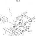
- the pasture grass water content determination device 10 includes a spectroscopy analyzer (corresponding to a "quality determination instrument") 9, a grass pressing device 12 and a supporting portion 13 in the form of a parallel link structure.
- the pasture grass water content determination device 10 further includes a frame 11 supported to the supporting portion 13.
- the grass pressing device 12 is supported to the frame 11 and presses the pasture grass 1 in a pasture land.
- the grass pressing device 12 includes a grass collecting portion 12a and a grass pressing portion 12b.
- the grass collecting portion 12a comprises a plate-like member and is attached to the frame 11 to protrude forwardly from this frame 11
- the language "forwardly” corresponds to the direction of traveling of a work vehicle mounting the pasture grass water content determination device 10 in work travel for determination of water content of the pasture grass 1.
- the bottom face of the grass collecting portion 12a has a shape which rises forwardly.
- the bottom face of the grass collecting portion 12a has a height from the ground surface which increases forwardly.
- the bottom face of the grass collecting portion 12a comprises combination of a curved face which protrudes upwards in the front area and a curved face which protrudes downwards in the base end side (rear side) area.
- the grass collecting portion 12a collects or gathers the pasture grass 1 in the area downwardly of this grass collecting portion 12a in an efficient manner and can guide them to the area downwardly of the frame 11.
- the grass pressing portion 12b is provided in the bottom area of the frame 11.
- the pasture grass 1 collected in the grass collecting portion 12a will be pressed along the slope of the grass collecting portion 12a and their compressed state is maintained in the area downwardly of the grass pressing portion 12b.
- the grass pressing portion 12b comprises a plate-like member or a member which is flat at least in its lower face. Relative to the bottom face of the grass pressing portion 12b, the grass collecting portion 12a is inclined, and the bottom face of the grass pressing portion 12b and the grass collecting portion 12a are formed continuous with each other. For instance, the grass pressing portion 12b and the grass collecting portion 12a will be formed integral with each other.
- a spectroscopy analyze 9 is provided in the grass pressing portion 12b and determines the water content of the pasture grass 1.
- the spectroscopy analyzer 9 irradiates a light 7 (see Fig. 4 ) such as near infrared beam from a determination head 8 and receives the light 7 which passed through the pasture grass 1 and returned after repeated reflections. Then, the spectroscopy analyzer 9 analyzes the received light 7 (see Fig. 4 ) to determine the water content of the pasture grass 1.
- An opening 12c is provided in the grass pressing portion 12b.
- the spectroscopy analyzer 9 is supported to the grass pressing portion 12b by being fitted in the opening 12c of this grass pressing portion 12b.
- the spectroscopy analyzer 9 can irradiate the light 7 (see Fig. 4 ) onto the pasture grass 1 which have been compressed sufficiently by the grass pressing device 12, so that as has been described in details with reference to Fig. 4 , diffused reflection of the irradiated light 7 (see Fig. 4 ) by the pasture grass 1 can be suppressed.
- the spectroscopy analyzer 9 can determine the water content of the pasture grass 1 with high accuracy by appropriately receiving the light (see Fig. 4 ) which has passed through the pasture grass 1.
- a work vehicle relating to this embodiment mounts the pasture grass water content determination device 10 described above.
- Fig. 11 in combination with Fig. 10 modes of using the pasture grass water content determination device 10 by the work vehicle relating to this embodiment will be explained.
- the following explanation is explanation using a tractor T as the work vehicle.
- the pasture grass water content determination device 10 is mounted on the tractor T with the supporting portion 13 being connected to the machine body front end (e.g. the front end of the machine body frame).
- the supporting portion 13 comprises a parallel link structure, so the pasture grass water content determination device 10 is vertically pivotable relative to the tractor T; thus vertical pivotal movements relative to the tractor T are allowed
- the supporting portion 13 comprises a parallel link structure
- the grass pressing portion 12b is constantly maintained parallel with the ground surface. As a result, the grass pressing portion 12b can compress the pasture grass 1 uniformly.
- the pasture grass water content determination device 10 may be used either when the tractor T travels forwardly or when the tractor T travels reversely. But, this pasture grass water content determination device 10 will be mounted such that the grass collecting portion 12a is oriented toward the front side in the advancing direction of the tractor T. Namely, the pasture grass water content determination device 10 will be mounted such that the grass collecting portion 12a is positioned more forwardly than the grass pressing portion 12b on the front side in the advancing direction of the tractor T.
- pasture grass 1 grown in a pasture land are reaped and sun-dried (dried) in the pasture land, if needed.
- the pasture grass 1 may be left in the pasture land when appropriate and laid in the form of ridge for example.
- the tractor T will travel on such reaped pasture grass 1 in the pasture land, and in association with traveling of the tractor T, the grass pressing device 12 compresses the pasture grass 1. And, the spectroscopy analyzer 9 will determine the water content of the pasture grass 1 under the compressed state.
- the pasture grass water content determination device 10 relating to the present embodiment, due to the inclusion of the grass pressing device 12, can press and compress the pasture grass 1, so that the spectroscopy analyzer 9 can irradiate the light 7 onto the pasture grass 1 under the dense state; therefore, the water content of the pasture grass 1 can be determined accurately.
- the spectroscopy analyzer 9 determines the water content of the pasture grass 1 with use of the light 7, accurate determination of the water content becomes impossible if light incident from the outside other than the light 7 irradiated by the spectroscopy analyzer 9 enters the determination head 8.
- the spectroscopy analyzer 9 is disposed within the opening 12c provided in the grass pressing portion 12b.
- the spectroscopy analyzer 9 will be disposed such that the bottom face of the spectroscopy analyzer 9 is substantially flush with the bottom face of the grass pressing portion 12b.
- the determination head 8 of the spectroscopy analyzer 9 can irradiate the light 7b onto the pasture grass 1 which are being pressed by the grass pressing portion 12b and the spectroscopy analyzer 9; and in addition, since the grass pressing portion 12b is larger than the spectroscopy analyzer 9, the water content can be determined for the pasture grass 1 in the area where intrusion of light is blocked by the spectroscopy analyzer 9 and the grass pressing portion 12b. As a result, incidence of light to the determination head 8 from the outside is suppressed, so that the water content of the pasture grass 1 can be determined even more accurately,
- the pasture grass water content determination device 10 is disposed forwardly of the area of the roll baler Ba for collecting the pasture grass 1 as described above, the water content of the pasture grass 1 can be determined immediately before a roll bale is formed by the roll baler Ba. Therefore, in accordance with the water content of the pasture grass 1, it is possible take some appropriate measure such as addition of an additive required for water content adjustment in the process of forming the roll bale or suspending the formation of the roll bail per se.
- the pasture grass water content determination device 10 may be mounted not only to the roll baler Ba towed by the tractor T or the self-propelled roll baler Ba, but also to work vehicles of various configurations such as a loader wagon towed by the tractor T or a self-propelled loader wagon. With this, it is possible take some appropriate measure such as addition of an additive required for water content adjustment in the process of forming the roll bale or suspending the formation of the roll bale per se, in the course of various works carried out by the work vehicle.
- the work vehicle mounting the pasture grass water content determination device 10 may effect the determination of water content of the pasture grass 1 not only for reaped pasture grass 1, but also may effect the determination of water content of the pasture grass 1, in addition to reaping of these pasture grass 1.
- the pasture grass water content determination device 10 may be provided in a rear area or a lower area of the tractor T mounting a reaping section M in its front area. Further alternatively, the pasture grass water content determination device 10 may be provided in a rear area or a lower area of a self-propelled tractor T.
- the reaping section M mounted on the tractor T or the self-propelled grass mower vehicle will reap the pasture grass 1 planted in a pasture land.
- the reaped pasture grass 1 in the pasture land will be compressed in association with passage of the pasture grass water content determination device 10 thereon and the water content thereof will be determined, With this, the water content of the pasture grass 1 can be determined with high accuracy in an efficient manner.
- the configuration of the grass pressing device 12 is not limited to the configuration of compressing the pasture grass 1 in association with traveling. Alternatively, the grass pressing device 12 may be configured to mechanically press the pasture grass 1.
- the grass pressing portion 12b may omit the opening 12c, and the pasture grass water content determination device 10 may be provided at any desired position as long as it can determine the water content of the pasture grass 1 under the compressed state.
- the pasture grass water content determination device 10 may be configured to be supported to the lower face of the grass pressing portion 12b.
- the use of the spectroscopy analyzer 9 is not limited to the determination of water content.
- the spectroscopy analyzer 9 can be used also for determinations of various qualities (properties) which can be determined optically.
- the light 7 is not limited near infrared beam, but it may be any electromagnetic wave such as microwave.
- the method of determination of qualities such as water content is not limited to the spectroscopy analysis, but the determination may employ various kinds of determination instruments or determination methods.
- the pasture grass water content determination device 10 may include an elastic body (not shown) such as a spring for urging the grass pressing device 12 downwards. With this, thanks to the elastic force of the elastic body (not shown) such a spring, the grass pressing portion 12b will be pressed downwards to press the pasture grass 1 in a reliable manner.
- an elastic body such as a spring for urging the grass pressing device 12 downwards.
- the bottom face of the grass collecting portion 12a is not limited to the combination of two curved faces, but may include only one curved face protruding downwards. Further alternatively, the bottom face of the grass collecting portion 12a need not include any curved face at all. Further alternatively, the grass collecting portion 12a may have a shape whose left and right opposed ends rise up progressively.
- the spectroscopy analyzer 9 may be mounted on the grass pressing portion 12b at its opening 12c. In this case, the spectroscopy analyzer 9 will be supported such that the determination head 8 is disposed in the opening 12c to be positioned close to the compressed pasture grass 1 downwardly of the determination head 8.
- the present invention allows determination of qualities of not only pasture grass, but of various kinds of plants and can be suitably used in various kinds of work vehicle.
Landscapes
- Life Sciences & Earth Sciences (AREA)
- Physics & Mathematics (AREA)
- Environmental Sciences (AREA)
- Spectroscopy & Molecular Physics (AREA)
- Analytical Chemistry (AREA)
- Chemical & Material Sciences (AREA)
- Health & Medical Sciences (AREA)
- Biochemistry (AREA)
- General Health & Medical Sciences (AREA)
- General Physics & Mathematics (AREA)
- Immunology (AREA)
- Pathology (AREA)
- Investigating Or Analysing Materials By Optical Means (AREA)
Abstract
Description
- The present invention relates to a work vehicle configured to determine quality of harvested pasture grass while traveling.
- Pasture grass are employed as forage for livestock. Pasture grass employed as such forage are stored in e.g, a silo after their mowing in a pasture land or sun-dried firstly in the pasture land and then formed into a cylindrical roll bale and collected as such, Pasture grass are generally subjected to butyric acid fermentation for their nutritional improvement. In butyric acid fermentation, mold may be generated if the water content is too high. Further, in order to allow the fermentation to proceed appropriately, there arises a need to add an additive such as formic acid or the like. Thus, for allowing appropriate butyric acid fermentation, management of the water content of pasture grass is important. As disclosed in
Patent Document 1, for determination of water content of pasture grass, it has been conventionally practiced to determine the water content of pasture grass using e.g. a water content determination device on pasture grass left in the pasture land immediately after their harvest or pasture grass collected in the pasture land after their harvest. Such water content determination device determines water content by irradiating light onto the pasture grass and then effecting a spectroscopic analysis of reflected light. - Patent Document 1:
Japanese Unexamined Patent Application Publication No 2018-185594 - However, pasture grass left or collected in a pasture land are present in a sparse state with gaps present between the pasture grass. For this reason, when light is irradiated onto the pasture grass, there occurs diffused reflection, which prevents the water content determination device from receiving the light passed through the pasture grass appropriately. As a result, appropriate water content determination may sometimes become impossible. This problem is not limited to water content determination, but occurs also with other determination devices determining various qualities.
- For solving the above-described problem, the object of the present invention is to determine quality of pasture grass with high accuracy.
- For accomplishing the above-noted object, a work vehicle relating to one embodiment of the present invention comprises a work vehicle configured to carry out work travel in a pasture land where harvested pasture grass are left, the work vehicle comprising a quality determination device configured to determine quality of pasture grass in a course of the work travel;
wherein the quality determination device includes: - a cylindrical grass sending tube;
- a grass taking section configured to feed at least a portion of the pasture grass left in the pasture land to an inside of the grass sending tube via a first end of the grass sending tube; and
- a quality determination instrument configured to determine quality of the pasture grass compressed inside the grass sending tube.
- Harvested pasture grass will be left over in the pasture land under a natural state without application thereto of any special pressure except for the gravity. For this reason, the pasture grass will be deposited in a sparse state, with the pasture grass being present having gaps therebetween. If quality determination is attempted on such pasture grass by irradiation of e.g. light thereon, diffused reflection may occur in the detection media such as light or the like (to be referred to simply as "light or the like" hereinafter), thus disabling appropriate quality determination.
- With the above-described arrangement, in association with traveling of the work vehicle, the grass taking section takes in the pasture grass in the pasture land and packs them into the grass sending pipe (the grass sending tube). With this, the pasture grass present in a sparse state will be gradually compressed inside the grass sending pipe. As a result, the quality determination instrument can carry out quality determination with irradiation of light to the pasture grass having reduced gaps, so that the quality of the pasture grass can be determined with high accuracy with effective suppression of diffused reflection of the light or the like.
- Further, there sometimes exists unevenness of quality in the left pasture grass between the upper layer part and the lower layer part of the pasture land. With the above-described inventive arrangement, the pasture grass are stirred and mixed when being taken in by the grass taking section. As a result, the pasture grass having varied qualities will be fed in a mixed state to the quality determination instrument, so that determination of average quality of pasture grass left in the pasture land becomes possible.
- A work vehicle relating to one embodiment of the present invention includes a work vehicle including a harvesting section and configured to carry out harvesting travel in a pasture land, and a quality determination device configured to determine quality of pasture grass while carrying out work travel;
wherein the quality determination device includes: - a cylindrical grass sending tube;
- a grass taking section configured to feed at least a portion of pasture grass harvested by the harvesting section to an inside of the grass sending tube via a first end of the grass sending tube; and
- a quality determination instrument configured to determine quality of the portion of the pasture grass compressed inside the grass sending tube.
- With the above-described arrangement, in association with traveling of the work vehicle, the grass taking section takes in the pasture grass harvested by the harvesting section and feeds and packs them into the grass sending tube. With this, the pasture grass present in a sparse state will be gradually compressed inside the grass sending tube. As a result, the quality determination instrument can carry out quality determination with irradiation of light to the pasture grass having reduced gaps, so that the quality of the pasture grass can be determined with high accuracy with effective suppression of diffused reflection of the light or the like.
- Further, preferably, the portion of the pasture grass sent into the grass sending tube are discharged via the other end (a second end) of the grass sending tube to be merged with a portion of the pasture grass which was not sent into the grass sending tube.
- With the above arrangement, as the pasture grass used in the quality determination are returned to the pasture grass which were not used for the determination, the pasture grass can be used without waste.
- Further preferably, the work vehicle further comprises a conveying path for collecting and conveying the pasture grass, wherein one end (first end) and the other end (second end) of the grass sending tube are connected to the conveying path, and the grass sending tube bypasses the conveying path.
- As examples of work vehicle, there are a harvester configured to collect pasture grass in a pasture land and stack them on a loader wagon, a truck, etc., and a roll baler configured to collect pasture grass in a pasture land and to form them into a roll bale. Such work vehicles have a conveying path for conveying collected pasture grass. The quality determination device can be mounted on these work vehicles also, and the quality determination device can be incorporated in the conveying path included in the work vehicles. If the quality determination device is included in the conveying path, quality determination can be carried out on each batch of collected pasture grass. Further, as the quality determination of pasture grass can be carried out in the course or a work, if the quality is found inappropriate, it is possible to take such measure as adding an additive to the pasture grass or suspending the work. As a result, improvement of work efficiency is made possible.
- Further, preferably, the grass taking section is configured to adjust an amount of pasture grass to be sent into the grass sending tube in proportion with a traveling speed of the work vehicle.
- With the above-described arrangement, an appropriate amount of pasture grass are sent into the grass sending tube at an appropriate speed, so that the pasture grass can be compressed in an efficient manner.
- Further, preferably, the grass sending tube has a sectional area that is progressively decreased in at least a part of a section from the first end of the grass sending tube to an area where the quality determination device is disposed.
- By progressively decreasing the cross sectional area of the grass sending tube toward the quality determination device, the pasture grass can be compressed in an efficient manner. Thus, diffused reflection of the light or the like can be suppressed easily, and the quality of pasture grass can be determined with high accuracy.
- A work vehicle relating to one embodiment of the present invention comprises a work vehicle configured to carry out work travel in a pasture land, the work vehicle comprising a quality determination device configured to determine quality of pasture grass while carrying out the work travel;
wherein the quality determination device includes: - a grass pressing device for pressing the pasture grass;
- a quality determination instrument configured to determine the quality of the pasture grass pressed by the grass pressing device; and
- a supporting portion configured to support the grass pressing device vertically movably relative to the work vehicle.
- Harvested pasture grass will be left in the pasture land under a natural state without application thereto of any special pressure except for the gravity. For this reason, the pasture grass will be deposited in a sparse state, with the pasture grass being present with gaps therebetween. If quality determination is attempted on such pasture grass by irradiation of e.g. light thereon, diffused reflection may occur in the detection media such as light or the like (to be referred to simply as "light or the like" hereinafter), thus disabling appropriate quality determination.
- With the above-described arrangement, in association with traveling of the work vehicle, the grass pressing device presses the pasture grass to reduce the gaps therebetween, so the quality determination device can carry out the quality determination of the pasture grass under a dense state thereof. Further, since the grass pressing device is supported vertically movably, the grass pressing device can move up and down in response to repulsive force from the pasture grass. Therefore, there will not occur such inconvenience of the grass pressing device getting hooked with the grass to push out the pasture grass forwardly. Thus, the pasture grass can be pressed in an appropriate manner. For the reasons mentioned above, the work vehicle can determine the quality of pasture grass with high accuracy, with effective suppression of diffused reflection of the light or the like.
- Further, preferably, the grass pressing device includes an elastic body configured to press down the grass pressing device.
- With the above-described arrangement, as the grass pressing device can press the pasture grass more effectively by the elastic force of the elastic body, the diffused reflection of the light or the like can be suppressed to allow high accuracy determination of the quality of pasture grass.
- Preferably, the supporting portion is vertically pivotally supported by a machine body of the vehicle.
- With the above-described arrangement, even if the pasture grass are left under an undulated state, as the grass pressing device follows the undulation thanks to the vertically pivotable supporting portion, the pasture grass can be pressed in a more appropriate manner, whereby the diffused reflection of the light or the like can be suppressed to allow high accuracy quality determination of the pasture grass.
- Preferably, the grass pressing device has an opening at which the quality determination instrument is provided.
- If the quality determination device were provided in the face of the grass pressing device which presses the pasture grass, unevenness would be formed in this face of the grass pressing device which presses the pasture grass, which makes it impossible to press the grass in an efficient manner. With the above-described arrangement, the quality determination instrument can be provided in the reverse face of the grass pressing device relative to its grass pressing face. Therefore, the pasture grass can be pressed by the entire grass pressing face of the grass pressing device. As a result, the pasture grass can be pressed in an efficient manner.
- Preferably:
- the quality determination device is mounted on and supported by the grass pressing device to determine the quality of the pasture grass through the opening; and
- the grass pressing device protrudes from the quality determination instrument on an outer circumferential side.
- The quality determination instrument may suffer from determination accuracy reduction due to influence from light incident from the outside. With the above-described arrangement, as the quality determination instrument is provided in the reverse face of the grass pressing face of the grass pressing device, the light can be irradiated onto the compressed pasture grass through the opening. Simultaneously, the grass pressing device can block light incident on the quality determination instrument from the outside. For the reasons mentioned above, even higher quality determination of pasture grass is made possible.
-
-
Fig. 1 is a perspective view illustrating a configuration of a pasture grass water content determination device, -
Fig. 2 is a side view illustrating a condition or form of pasture grass at the time of water content determination, -
Fig. 3 is a view illustrating a work vehicle on which the pasture grass water content determination device is mounted, -
Fig. 4 is a view for explaining relationship between density of pasture grass and traveling of light, -
Fig. 5 is a view illustrating a work vehicle on which the pasture grass water content determination device is mounted, -
Fig. 6 is a view illustrating a work vehicle on which the pasture grass water content determination device is mounted, -
Fig. 7 is a view illustrating a work vehicle on which the pasture grass water content determination device is mounted, -
Fig. 8 is a view illustrating a form of the pasture grass water content determination device to be mounted on a conveying device, -
Fig. 9 is a perspective view illustrating an arrangement of the pasture grass water content determination device, -
Fig. 10 is a section view illustrating a mounting arrangement of the pasture grass water content determination device, -
Fig. 11 is a view illustrating a work vehicle on which the pasture grass water content determination device is mounted, -
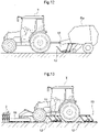
Fig. 12 is a view illustrating a work vehicle on which the pasture grass water content determination device is mounted, and -
Fig. 13 is a view illustrating a work vehicle on which the pasture grass water content determination device is mounted. - Firstly, an example of arrangement of a pasture grass water content determination device (corresponding to a "quality determination device") to be mounted on a work vehicle relating to this embodiment will be explained.
- A pasture grass water
content determination device 20 is configured to take in harvested or reapedpasture grass 1 and compress them and then to determine the water content of thepasture grass 1 under their compressed state. This pasture grass watercontent determination device 20 is mounted on a work vehicle which travels in a pasture land and determines the water content of thepasture grass 1 while moving in association of traveling of the work vehicle. The pasture grass watercontent determination device 20 includes a spectroscopy analyzer (corresponding to a "quality determination instrument") 9, agrass sending tube 21 and a raking-in section (corresponding to a "grass taking section") 22. - The
grass sending tube 21 comprises a tubular structure including twoside walls 21a, abottom portion 21b and atop plate portion 21c. For instance, all of theside walls 21a, thebottom portion 21b and thetop plate portion 21c are plate-like members. Each one of the twoside walls 21a is disposed erect at the opposed ends of thebottom portion 21b and face each other. Thetop plate portion 21c, in the area forwardly of thegrass sending tube 21, extends across and between the twoside walls 21a and faces thebottom portion 21b. Here, the front end portion of thegrass sending tube 21 corresponds to the inlet of thegrass sending tube 21 via which thepasture grass 1 are taken in. - The raking-in
section 22 is supported to be pivotable about an axis P extending between the twoside walls 21a, with the raking-insection 22 extending across and between the twoside walls 21a in the area forwardly of thegrass sending tube 21. The raking-insection 22 includes acylinder 22a andblades 22b. Thecylinder 22a is a cylindrical member rotatable about the axis P. Theblades 22b protrude from thecylinder 22a and are provided in a plurality on the surface of thecylinder 22a in juxtaposition in the rotational direction. In operation, as theblades 22b are rotated about the axis P in association with rotation of thecylinder 22a, thepasture grass 1 are raked in to be packed inside thegrass sending tube 21. For instance, foursuch blades 22b will be provided on thecylinder 22a. Further, preferably, eachblade 22b has a plurality ofpawls 22c at its leading end. With provision ofsuch pawls 22c, theblades 22b can rake in thepasture grass 1 in an efficient manner. Further alternatively, eachblade 22b may be bent in the rotational direction at its leading end area. With this arrangement too, theblades 22b can rake in thepasture grass 1 in an efficient manner. - The raking-in
section 22 rakes in at least some of thepasture grass 1 and packs them one after another to the inside of thegrass sending tube 21 via its inlet. Thus, thepasture grass 1 inside the grass sending tube21 are compressed to obtain a higher density. Thepasture grass 1 which have passed through the inside of thegrass sending tube 21 are discharged via a discharging output which is the rear end of thegrass sending tube 21. The dischargedpasture grass 1 are merged withpasture grass 1 which were not raked in. - The
spectroscopy analyzer 9 is disposed across and between the twoside walls 21a in the upper area of thegrass sending tube 21. For instance, thespectroscopy analyzer 9 will be disposed rearwardly of thetop plate portion 21c and placed in contact with thistop plate portion 21c. Thespectroscopy analyzer 9 is disposed toward adetermination head 8 inside thegrass sending tube 21 between the twoside walls 21a to face thepasture grass 1 compressed inside thegrass sending tube 21. With these arrangements, thespectroscopy analyzer 9 can determine a water content of thepasture grass 1 which were compressed inside thegrass sending tube 21. Thespectroscopy analyzer 9 irradiates a light 7 (seeFig. 4 ) such as near infrared beam from thedetermination head 8 and receives the light which passed through thepasture grass 1 and returned after repeated reflections. Then, thespectroscopy analyzer 9 analyzes the received light 7 (seeFig. 4 ) to determine the water content of thepasture grass 1. - With the above-described arrangements, the
spectroscopy analyzer 9 can irradiate the light 7 (seeFig. 7 ) onto thepasture grass 1 which have been sufficiently compressed inside thegrass sending tube 21, so that as will be described later with reference toFig. 4 , diffused reflection of the irradiated light 7 (seeFig. 4 ) by thepasture grass 1 is suppressed. As a result, thespectroscopy analyzer 9 can determine the water content of thepasture grass 1 with accuracy by appropriately receiving the light (seeFig. 4 ) which passed through thepasture grass 1. - Further, since the
grass sending tube 21 has an annular structure, light is shielded at least in the vicinity of thespectroscopy analyzer 9 inside thegrass sending tube 21 and incidence of light from the outside to thepasture grass 1 packed inside thegrass sending tube 21 is suppressed. For this reason too, thespectroscopy analyzer 9 can determine the water content of thepasture grass 1 with high accuracy by receiving only the light (seeFig. 4 ) which passed through thepasture grass 1. - Moreover, in the
left pasture grass 1, due to e.g. difference of drying speeds, unevenness of their water contents may occur therein between the upper layer area and the lower layer area of the pasture land. With use of a pasture grass watercontent determination device 20, thepasture grass 1 are stirred and mixed together when they are raked in by the raking-insection 22. As a result, thepasture grass 1 having uneven water contents are fed in a mixed state to thespectroscopy analyzer 9, so that thespectroscopy analyzer 9 can determine an average water content of thepasture grass 1 left in the pasture land. - A work vehicle relating to this embodiment mounts the pasture grass water
content determination device 20 described above. Next, with reference toFig. 3 in combination withFig. 2 , modes of using the pasture grass watercontent determination device 20 by the work vehicle relating to this embodiment will be explained. The following explanation is explanation using a tractor T as the work vehicle. - The pasture grass water
content determination device 20 is mounted on the tractor T, with a supportingportion 13 being connected to a machine body front end (e.g. the front end of the machine body frame) of the tractor T. - The pasture grass water
content determination device 20 may be used in the case of the tractor T traveling forwardly or in the case of the tractor T traveling reversely. Yet, under its in-use state, the pasture grass watercontent determination device 20 will be mounted in such a manner that the inlet of thegrass sending tube 21 is oriented to the front side in the advancing direction of the tractor T. Namely, the pasture grass watercontent determination device 20 is mounted such that the raking-insection 22 is positioned forwardly of thespectroscopy analyzer 9, relative to the front side of the advancing direction of the tractor T. - Here,
pasture grass 1 grown in a pasture land are reaped and sun-dried (dried) in the pasture land, if needed. Sometimes, for readiness of collecting thepasture grass 1, thepasture grass 1 may be left in the pasture land when appropriate and laid in the form of ridge. A tractor T will travel onsuch pasture grass 1 reaped in the pasture land and the raking-insection 22 will rake in thepasture grass 1 in association with traveling of the tractor T and thepasture grass 1 will be compressed inside thegrass sending tube 21. And, thespectroscopy analyzer 9 determines the water content of thepasture grass 1 under the compressed state. - Next, with reference to
Fig. 4 , there will be explained traveling of the light 7 irradiated at the time of determination of the water content and accuracy of the determination. - As described above, the reaped
grass 1 are left in the pasture land when necessary and then thepasture grass 1 will be left as they are after being reaped or collected in the form of ridge for facilitating subsequent work. In either case, thepasture grass 1 in a pasture land are present under a natural state without being subjected to any special compression and exist in a sparse state with gaps present therebetween - In this way, if the
light 7 is irradiated from thespectroscopy analyzer 9 onto thepasture grass 1 which are under such sparse state, thelight 7 will be reflected by thepasture grass 1 due to the spaces present between thepasture grass 1. If diffused reflection of theirradiated light 7 occurs as described above, the light will be scattered in an uncontrolled manner, so the light 7 may fail to return to thedetermination head 8 of thespectroscopy analyzer 9. In this case, determination of the water content of thepasture grass 1 becomes impossible. As a result, relative to theirradiated light 7, the ratio of thelight 7 returning to thedetermination head 8 becomes smaller, making accurate determination of the water content of thepasture grass 1 impossible. - On the other hand, if the
light 7 is irradiated from thespectroscopy analyzer 9 onto thepasture grass 1 which are under a dense state, thelight 7 passed through acertain pasture grass 1 will reachnext pasture grass 1 immediately, so diffused reflection occurs less likely. Thus, the light which has passed through somepasture grass 1 will not diffuse and will readily return to thedetermination head 8. As a result, there is high likelihood of a sufficient amount oflight 7 returning to thedetermination head 8 after passage through thepasture grass 1, so that accurate determination of water content of thepasture grass 1 is made possible. - And, since such accurate determination of water content of the
pasture grass 1 is made possible, it becomes possible to make a work plan at a timing optimal for carrying out a next work or to take such an action as adding an additive, etc. Further, if a communication device (not shown) is provided additionally for transmitting the determined water content to a server or the like for managing a silo, etc., it will become possible to manage the silo or the like in accordance with the water content of thepasture grass 1 stored therein. For the reasons mentioned above, high quality forage can be produced easily. Moreover, since the water content determination is possible while traveling in the pasture land in a scanning manner, if position information of the pasture land can be obtained by means of e.g. GPS or the like, the position information and the water content can be correlated with each other to generate the distribution of water content in the pasture land in the form of a map also. - As shown in
Fig. 1, Fig. 2 andFig. 4 , the pasture grass watercontent determination device 20 relating to this embodiment allows thespectroscopy analyzer 9 to irradiate thelight 7 onto thepasture grass 1 under a dense state by pushing thepasture grass 1 into thegrass sending tube 21 for their compression therein. Therefore, the water content of thepasture grass 1 can be determined accurately. - Here, since the
spectroscopy analyzer 9 determines the water content of thepasture grass 1 with use of thelight 7, accurate determination of the water content becomes impossible if light incident from the outside other than the light 7 irradiated by thespectroscopy analyzer 9 enters thedetermination head 8. - Then, in the pasture grass water
content determination device 20 relating to this embodiment, as described above, thespectroscopy analyzer 9 is installed in such a manner to cover the area upwardly of thegrass sending tube 21. Therefore, thedetermination head 8 of thespectroscopy analyzer 9 can irradiate thelight 7 onto thepasture grass 1 which are covered by thespectroscopy analyzer 9, so that the water content of thepasture grass 1 can be made in the area where intrusion of light is blocked by thegrass sending tube 21 including thespectroscopy analyzer 9. Consequently, incidence of light from the outside to thedetermination head 8 is suppressed and the water content of thepasture grass 1 can be determined even more accurately. -
- (1) The pasture grass water
content determination device 20 can be disposed to protrude rearwardly from the machine body rear end of the tractor T. In this case, the pasture grass watercontent determination device 20, when used, will be towed on the pasture land in association with forward traveling of the tractor T. Further, the pasture grass watercontent determination device 20 can be disposed at a lower portion of the tractor T, e.g. between the front andrear wheels 4, in which case the pasture grass watercontent determination device 20 when used will be used to move on the pasture land in association with forward traveling of thetractor 20. - (2) The work vehicle on which the pasture grass water
content determination device 20 is mounted is not limited to a tractor T, but may be various kinds of work vehicles or a tractor T mounting various implements for carrying out various kinds of utility works. And, the pasture grass watercontent determination device 20 mounted on such work vehicles will takepasture grass 1 left in a pasture land into thegrass sending tube 21 and determine the water content thereof inside thisgrass sending tube 21. - For instance, the pasture grass water
content determination device 20, as shown inFig. 5 , may be provided in a rear area or a lower area of a tractor T mounting a reaping section M in a front area thereof. Further alternatively, the pasture grass watercontent determination device 20 may be provided in a front area, a rear area or a lower area of a self-propelled grass mower vehicle. Thus, the device may be provided in any area where it can be mounted. - The reaping section M mounted on a tractor T or the self-propelled grass mower vehicle will reap
pasture grass 1 planted in a pasture land. Thepasture grass 1 reaped in the pasture land will be taken into thegrass sending tube 21 in association with passage of the pasture grass watercontent determination device 20 and their water content will be determined. With this, the water content of thepasture grass 1 can be determined accurately. - (3) Further, the work vehicle mounting the pasture grass water
content determination device 20 may be a work vehicle configured to carry out work travel while collecting thepasture grass 1 in a pasture land. Such work vehicles are equipped with a conveyingpath 3 for conveying the collectedpasture grass 1. Then, the pasture grass watercontent determination device 20 will be mounted to the conveyingpath 3 with bypassing this conveyingpath 3. - For example, as shown in
Fig. 6 , the work vehicle can be a harvester H. The harvester H collects thepasture grass 1 in a pasture land and discharges them onto a loader wagon W or the like. Then, the loader wagon W or the like will convey the collectedpasture grass 1 to a silo, etc. The harvester H will convey the collectedpasture grass 1 via the conveyingpath 3 and discharge thepasture grass 1 from the conveyingpath 3 onto the loader wagon W, etc. The pasture grass watercontent determination device 20 is mounted in this conveyingpath 3, with the inlet and the discharging outlet of the pasture grass watercontent determination device 20 being connected to the conveyingpath 3. For instance, the pasture grass watercontent determination device 20 may be mounted in the conveyingpath 3 via an attachment or the like. It will suffice as long as the raking-insection 22 can guide at least some of thepasture grass 1 conveyed in the conveyingpath 3 into thegrass sending tube 21. Further, as shown inFig. 8 , the pasture grass watercontent determination device 20 may include acurved portion 21d at least at one position of thegrass sending tube 21. With this, the pasture grass watercontent determination device 20 can be readily mounted in the conveyingpath 3 and also the pasture grass watercontent determination device 20 can be readily mounted in the conveyingpath 3 in such a manner to dispose the raking-insection 22 to readily rake in thepasture grass 1 inside the conveyingpath 3. - Moreover, as shown in
Fig. 7 , the work vehicle can be a tractor T which tows a roll baler Ba as an "implement" or a self-propelled type roll baler Ba. The roll baler Ba collectspasture grass 1 in a pasture land and forms thepasture grass 1 into a roll bale, The roll baler Ba conveys the collectedpasture grass 1 to an area for forming such a roll bale via the conveyingpath 3. And, the pasture grass watercontent determination device 20 will be mounted in this conveyingpath 3 with the inlet and the discharging outlet of the pasture grass watercontent determination device 20 being connected to the conveyingpath 3. For instance, the pasture grass watercontent determination device 20 may be mounted in the conveyingpath 3 via an attachment or the like. It will suffice as long as the raking-insection 22 can guide at least some of thepasture grass 1 conveyed in the conveyingpath 3 into thegrass sending tube 21. Further, the pasture grass watercontent determination device 20 such as the one as shown inFig. 8 may include acurved portion 21d in at least one position of thegrass sending tube 21. With this, the pasture grass watercontent determination device 20 can be readily mounted in the conveyingpath 3 and also the pasture grass watercontent determination device 20 can be readily mounted in the conveyingpath 3 in such a manner to dispose the raking-insection 22 to readily rake in thepasture grass 1 inside the conveyingpath 3. Incidentally, since the pasture grass watercontent determination device 20 illustrated inFigs. 6 through 8 is provided in the conveyingpath 3, the supportingportion 13 need not be provided. - As described above, if the pasture grass water
content determination device 20 is provided in a harvester H or a roll baler Ba, the water content of thepasture grass 1 can be determined immediately before thesepasture grass 1 are conveyed to a silo or the like or a roll bale is formed by the roll bailer Ba. Therefore, it becomes possible to effect any appropriate measure such as appropriately adjusting an additive to be added in the silo or the like or effecting addition of an additive required for water content adjustment in the process of roll bale formation or suspending the formation of roll bale per se. - (4) The cross sectional area of the
grass sending tube 21 may be uniform, but this cross sectional area alternatively may progressively decrease in the entiregrass sending tube 21 or in at least a part thereof before thespectroscopy analyzer 9, from the front end (inlet) to the rear end (discharging outlet). In this case, at least one of thebottom portion 21b, theside walls 21a and thetop plate portion 21c may be tilted to the inner side of thegrass sending tube 21, or an inclined face may be provided in the inner face of thegrass sending tube 21. Further, the arrangement of thegrass sending tube 21 is not limited to the arrangement having thebottom portion 21b, theside walls 22a and thetop plate portion 21c, but thegrass sending tube 21 may be any pipe into which raked-inpasture grass 1 are to be sent, and its cross sectional shape may be any shape. - (5) The
spectroscopy analyzer 9 can effect not only the determination of water content, but can effect also determination of various qualities (properties) which can be determined optically. Further, thelight 7 is not limited to near infrared beam, but may be other electromagnetic wave such as microwave, etc. Moreover, the technique of determining quality such as water content is not limited to spectroscopic analysis, but the technique may employ various kinds of determination instruments or determination methods such as determination using electrostatic capacitance. - (6) The
spectroscopy analyzer 9 may be provided across and between the twoside walls 21a. Alternatively, it may be supported, with gaps relative to the twoside walls 21a, - (7) The pasture grass water
content determination device 20 may be supported to the work vehicle via an elastic body (not shown) such as a spring. Specifically, the pasture grass watercontent determination device 20 may be supported to one end of the supportingportion 13 via an elastic body (not shown) such as a spring The other end of the supportingportion 13 is supported to the work vehicle. With this arrangement, when the pasture grass watercontent determination device 20 passes over thepasture grass 1 in association with traveling of the work vehicle, even if the pasture grass watercontent determination device 20 tends to rise due to the pressure from thepasture grass 1, the pasture grass watercontent determination device 20 will be pushed down by the elastic force of the elastic body (not shown) such as a spring. Therefore, the pasture grass watercontent determination device 20 will follow e.g. undulation of thepasture grass 1 and thepasture grass 1 can be raked in in more efficient manner. - (8) The
top plate portion 21c may be provided to extend to a position covering the raking-insection 22 from above or may be provided in such a manner not to cover the vicinity of the inlet of thegrass sending tube 21 in which the raking-insection 22 is provided. The raking-insection 22 may be pivotally supported inside thegrass sending tube 21, but as long as it can feed thepasture grass 1 into thegrass sending tube 21, the raking-insection 22 may be provided at a position away from thegrass sending tube 21. The raking-insection 22 acting as a "grass taking section" may be configured to take thepasture grass 1 into thegrass sending tube 21 with rotation of ablade 22b. But, it may have any arrangement as long as it can take thepasture grass 1 into thegrass sending tube 21. For instance, the raking-insection 22 may comprise a suction instrument for sucking thepasture grass 1. - (9) The
blade 22b may be provided as a single blade in the width direction of thecylinder 22a. Alternatively, a plurality ofblades 22b may be provided in the width direction of thecylinder 22a. Namely, at least one or some ofblades 22b disposed side by side in the circumferential direction of thecylinder 22a may comprise a plurality ofblades 22b juxtaposed in the width direction of thecylinder 22a - (10) The layout of the
spectroscopy analyzer 9 is not limited to the layout of it being provided in contact with thetop plate portion 21c rearwardly of thistop plate portion 21c, but it may be provided with a spacing relative to thetop plate portion 21c. Further, the end portion of thespectroscopy analyzer 9 may be placed on thetop plate portion 21c. - (11) The raking-in
section 22 can be configured to be capable of adjusting the amount ofpasture grass 1 to be fed into thegrass sending tube 21 in proportion with the traveling speed of the work vehicle. With this, an appropriate amount ofpasture grass 1 will be fed into thegrass sending tube 21 at an appropriate speed, so that thepasture grass 1 can be compressed in an efficient manner. For instance, the raking-insection 22 may be configured such that the rotational speed of thecylinder 22a is varied in accordance with the traveling speed of the work vehicle. - Firstly, with reference to
Fig. 9 andFig. 10 , an example of arrangement of a pasture grass water content determination device (corresponding to a "quality determination device") to be mounted on a work vehicle relating to this embodiment will be explained. - A pasture grass water
content determination device 10 is configured to compress reapedpasture grass 1 and to determine the water content of thepasture grass 1 under their compressed state. This pasture grass watercontent determination device 10 is mounted on a work vehicle which travels in a pasture land and determines the water content of thepasture grass 1 while moving in association of traveling of the work vehicle. The pasture grass watercontent determination device 10 includes a spectroscopy analyzer (corresponding to a "quality determination instrument") 9, a grasspressing device 12 and a supportingportion 13 in the form of a parallel link structure. The pasture grass watercontent determination device 10 further includes aframe 11 supported to the supportingportion 13. - The grass
pressing device 12 is supported to theframe 11 and presses thepasture grass 1 in a pasture land. The grasspressing device 12 includes agrass collecting portion 12a and agrass pressing portion 12b. - The
grass collecting portion 12a comprises a plate-like member and is attached to theframe 11 to protrude forwardly from thisframe 11 Here, the language "forwardly" corresponds to the direction of traveling of a work vehicle mounting the pasture grass watercontent determination device 10 in work travel for determination of water content of thepasture grass 1. The bottom face of thegrass collecting portion 12a has a shape which rises forwardly. In other words, the bottom face of thegrass collecting portion 12a has a height from the ground surface which increases forwardly. Specifically, the bottom face of thegrass collecting portion 12a comprises combination of a curved face which protrudes upwards in the front area and a curved face which protrudes downwards in the base end side (rear side) area. Thegrass collecting portion 12a, with the above-described arrangement, collects or gathers thepasture grass 1 in the area downwardly of thisgrass collecting portion 12a in an efficient manner and can guide them to the area downwardly of theframe 11. - The grass
pressing portion 12b is provided in the bottom area of theframe 11. Thepasture grass 1 collected in thegrass collecting portion 12a will be pressed along the slope of thegrass collecting portion 12a and their compressed state is maintained in the area downwardly of thegrass pressing portion 12b. The grasspressing portion 12b comprises a plate-like member or a member which is flat at least in its lower face. Relative to the bottom face of thegrass pressing portion 12b, thegrass collecting portion 12a is inclined, and the bottom face of thegrass pressing portion 12b and thegrass collecting portion 12a are formed continuous with each other. For instance, thegrass pressing portion 12b and thegrass collecting portion 12a will be formed integral with each other. - A spectroscopy analyze 9 is provided in the
grass pressing portion 12b and determines the water content of thepasture grass 1. Thespectroscopy analyzer 9 irradiates a light 7 (seeFig. 4 ) such as near infrared beam from adetermination head 8 and receives thelight 7 which passed through thepasture grass 1 and returned after repeated reflections. Then, thespectroscopy analyzer 9 analyzes the received light 7 (seeFig. 4 ) to determine the water content of thepasture grass 1. - An
opening 12c is provided in thegrass pressing portion 12b. Thespectroscopy analyzer 9 is supported to thegrass pressing portion 12b by being fitted in theopening 12c of thisgrass pressing portion 12b. - Thanks to the above-described arrangements, the
spectroscopy analyzer 9 can irradiate the light 7 (seeFig. 4 ) onto thepasture grass 1 which have been compressed sufficiently by the grasspressing device 12, so that as has been described in details with reference toFig. 4 , diffused reflection of the irradiated light 7 (seeFig. 4 ) by thepasture grass 1 can be suppressed. As a result, thespectroscopy analyzer 9 can determine the water content of thepasture grass 1 with high accuracy by appropriately receiving the light (seeFig. 4 ) which has passed through thepasture grass 1. - A work vehicle relating to this embodiment mounts the pasture grass water
content determination device 10 described above. Next, with reference toFig. 11 in combination withFig. 10 , modes of using the pasture grass watercontent determination device 10 by the work vehicle relating to this embodiment will be explained. The following explanation is explanation using a tractor T as the work vehicle. - The pasture grass water
content determination device 10 is mounted on the tractor T with the supportingportion 13 being connected to the machine body front end (e.g. the front end of the machine body frame). - The supporting
portion 13 comprises a parallel link structure, so the pasture grass watercontent determination device 10 is vertically pivotable relative to the tractor T; thus vertical pivotal movements relative to the tractor T are allowed - Further, since the supporting
portion 13 comprises a parallel link structure, thegrass pressing portion 12b is constantly maintained parallel with the ground surface. As a result, thegrass pressing portion 12b can compress thepasture grass 1 uniformly. - The pasture grass water
content determination device 10 may be used either when the tractor T travels forwardly or when the tractor T travels reversely. But, this pasture grass watercontent determination device 10 will be mounted such that thegrass collecting portion 12a is oriented toward the front side in the advancing direction of the tractor T. Namely, the pasture grass watercontent determination device 10 will be mounted such that thegrass collecting portion 12a is positioned more forwardly than thegrass pressing portion 12b on the front side in the advancing direction of the tractor T. - Here,
pasture grass 1 grown in a pasture land are reaped and sun-dried (dried) in the pasture land, if needed. Sometimes, for readiness of collecting thepasture grass 1, thepasture grass 1 may be left in the pasture land when appropriate and laid in the form of ridge for example. The tractor T will travel on such reapedpasture grass 1 in the pasture land, and in association with traveling of the tractor T, the grasspressing device 12 compresses thepasture grass 1. And, thespectroscopy analyzer 9 will determine the water content of thepasture grass 1 under the compressed state. - As shown in
Fig. 9 ,Fig. 10 andFig. 4 , the pasture grass watercontent determination device 10 relating to the present embodiment, due to the inclusion of the grasspressing device 12, can press and compress thepasture grass 1, so that thespectroscopy analyzer 9 can irradiate thelight 7 onto thepasture grass 1 under the dense state; therefore, the water content of thepasture grass 1 can be determined accurately. - Here, since the
spectroscopy analyzer 9 determines the water content of thepasture grass 1 with use of thelight 7, accurate determination of the water content becomes impossible if light incident from the outside other than the light 7 irradiated by thespectroscopy analyzer 9 enters thedetermination head 8. - In the case of the pasture grass water
content determination device 10 relating to this embodiment, as described above, thespectroscopy analyzer 9 is disposed within theopening 12c provided in thegrass pressing portion 12b. For instance, thespectroscopy analyzer 9 will be disposed such that the bottom face of thespectroscopy analyzer 9 is substantially flush with the bottom face of thegrass pressing portion 12b. Therefore, thedetermination head 8 of thespectroscopy analyzer 9 can irradiate the light 7b onto thepasture grass 1 which are being pressed by thegrass pressing portion 12b and thespectroscopy analyzer 9; and in addition, since thegrass pressing portion 12b is larger than thespectroscopy analyzer 9, the water content can be determined for thepasture grass 1 in the area where intrusion of light is blocked by thespectroscopy analyzer 9 and thegrass pressing portion 12b. As a result, incidence of light to thedetermination head 8 from the outside is suppressed, so that the water content of thepasture grass 1 can be determined even more accurately, -
- (1) The arrangement of the pasture grass water
content determination device 10 is not limited to the arrangement of it being vertically pivotally supported to the machine body. Alternatively, the pasture grass watercontent determination device 10 may be configured to be vertically slidably to the machine body. - (2) The pasture grass water
content determination device 10 may be disposed to protrude rearwardly from the machine body rear end of the tractor T, in which case the pasture grass watercontent determination device 10 is towed on the pasture land in association with forward traveling of the tractor T. Further alternatively, the pasture grass watercontent determination device 10 may be disposed at a lower portion of the tractor T, e.g. between the front andrear wheels 4, in which case the pasture grass watercontent determination device 10 will be moved on the pasture land in association with forward traveling of the tractor T. - (3) The work vehicle such as the tractor T may mount the pasture grass water
content determination device 10 only, but it may mount the pasture grass watercontent determination device 10 together with other implement. For example, as shown inFig. 12 , in the case of the tractor T mounting a roll baler Ba as an "implement", the pasture grass watercontent determination device 10 may be mounted to the roll bailer Ba, or may be mounted to a self-propelled roll baler Ba. In the latter case, the pasture grass watercontent determination device 10 will be disposed forwardly of the area of the roll baler Ba for collecting thepasture grass 1. - If the pasture grass water
content determination device 10 is disposed forwardly of the area of the roll baler Ba for collecting thepasture grass 1 as described above, the water content of thepasture grass 1 can be determined immediately before a roll bale is formed by the roll baler Ba. Therefore, in accordance with the water content of thepasture grass 1, it is possible take some appropriate measure such as addition of an additive required for water content adjustment in the process of forming the roll bale or suspending the formation of the roll bail per se. - Similarly, the pasture grass water
content determination device 10 may be mounted not only to the roll baler Ba towed by the tractor T or the self-propelled roll baler Ba, but also to work vehicles of various configurations such as a loader wagon towed by the tractor T or a self-propelled loader wagon. With this, it is possible take some appropriate measure such as addition of an additive required for water content adjustment in the process of forming the roll bale or suspending the formation of the roll bale per se, in the course of various works carried out by the work vehicle. - (4) Further, the work vehicle mounting the pasture grass water
content determination device 10 may effect the determination of water content of thepasture grass 1 not only for reapedpasture grass 1, but also may effect the determination of water content of thepasture grass 1, in addition to reaping of thesepasture grass 1. For instance, as shown inFig. 13 , the pasture grass watercontent determination device 10 may be provided in a rear area or a lower area of the tractor T mounting a reaping section M in its front area. Further alternatively, the pasture grass watercontent determination device 10 may be provided in a rear area or a lower area of a self-propelled tractor T. - The reaping section M mounted on the tractor T or the self-propelled grass mower vehicle will reap the
pasture grass 1 planted in a pasture land. The reapedpasture grass 1 in the pasture land will be compressed in association with passage of the pasture grass watercontent determination device 10 thereon and the water content thereof will be determined, With this, the water content of thepasture grass 1 can be determined with high accuracy in an efficient manner. - (5) The configuration of the grass
pressing device 12 is not limited to the configuration of compressing thepasture grass 1 in association with traveling. Alternatively, the grasspressing device 12 may be configured to mechanically press thepasture grass 1. - (6) The grass
pressing portion 12b may omit theopening 12c, and the pasture grass watercontent determination device 10 may be provided at any desired position as long as it can determine the water content of thepasture grass 1 under the compressed state. For instance, the pasture grass watercontent determination device 10 may be configured to be supported to the lower face of thegrass pressing portion 12b. - (7) The use of the
spectroscopy analyzer 9 is not limited to the determination of water content. Thespectroscopy analyzer 9 can be used also for determinations of various qualities (properties) which can be determined optically. Further, thelight 7 is not limited near infrared beam, but it may be any electromagnetic wave such as microwave. Further, the method of determination of qualities such as water content is not limited to the spectroscopy analysis, but the determination may employ various kinds of determination instruments or determination methods. - (8) The pasture grass water
content determination device 10 may include an elastic body (not shown) such as a spring for urging the grasspressing device 12 downwards. With this, thanks to the elastic force of the elastic body (not shown) such a spring, thegrass pressing portion 12b will be pressed downwards to press thepasture grass 1 in a reliable manner. - (9) The bottom face of the
grass collecting portion 12a is not limited to the combination of two curved faces, but may include only one curved face protruding downwards. Further alternatively, the bottom face of thegrass collecting portion 12a need not include any curved face at all. Further alternatively, thegrass collecting portion 12a may have a shape whose left and right opposed ends rise up progressively. - (10) The
spectroscopy analyzer 9 may be mounted on thegrass pressing portion 12b at itsopening 12c. In this case, thespectroscopy analyzer 9 will be supported such that thedetermination head 8 is disposed in theopening 12c to be positioned close to the compressedpasture grass 1 downwardly of thedetermination head 8. - The present invention allows determination of qualities of not only pasture grass, but of various kinds of plants and can be suitably used in various kinds of work vehicle.
-
- 1:
- pasture grass
- 3:
- conveying path
- 9:
- spectroscopy analyzer (quality determination instrument)
- 10:
- pasture grass water content determination device (quality determination device)
- 12:
- grass pressing device
- 12c:
- opening
- 13:
- supporting portion
- 15:
- elastic body
- 20:
- pasture grass water content determination device (quality determination device)
- 21:
- grass sending tube
- 22:
- raking-in section (grass taking section)
- Ba:
- roll baler (work vehicle)
- H:
- harvester (work vehicle)
- M:
- reaping section
- T:
- tractor (work vehicle)
Claims (11)
- A work vehicle configured to carry out work travel in a pasture land where harvested pasture grass are left, the work vehicle comprising:a quality determination device configured to determine quality of pasture grass in a course of the work travel;wherein the quality determination device includes:a cylindrical grass sending tube;a grass taking section configured to feed at least a portion of the pasture grass left in the pasture land to an inside of the grass sending tube via a first end of the grass sending tube; anda quality determination instrument configured to determine quality of the pasture grass compressed inside the grass sending tube.
- A work vehicle comprising:a harvesting section for the work vehicle to carry out harvesting travel in a pasture land; anda quality determination device configured to determine quality of pasture grass while carrying out work travel;wherein the quality determination device includes:a cylindrical grass sending tube;a grass taking section configured to feed at least a portion of pasture grass harvested by the harvesting section to an inside of the grass sending tube via a first end of the grass sending tube; anda quality determination instrument configured to determine quality of the portion of the pasture grass compressed inside the grass sending tube.
- The work vehicle of claim 1 or 2, wherein the portion of the pasture grass sent into the grass sending tube are discharged via a second end of the grass sending tube to be merged with a portion of the pasture grass which was not sent into the grass sending tube.
- The work vehicle of claim 3, further comprising:a conveying path for collecting and conveying the pasture grass,wherein the first end and the second end of the grass sending tube are connected to the conveying path, andthe grass sending tube bypasses the conveying path.
- The work vehicle of any one of claims 1-4, wherein the grass taking section is configured to adjust an amount of pasture grass to be sent into the grass sending tube in proportion with a traveling speed of the work vehicle.
- The work vehicle of any one of claims 1-5, wherein the grass sending tube has a sectional area that is progressively decreased in at least a part of a section from the first end of the grass sending tube to an area where the quality determination device is disposed.
- A work vehicle configured to carry out work travel in a pasture land, the work vehicle comprising:a quality determination device configured to determine quality of pasture grass while carrying out the work travel;wherein the quality determination device includes:a grass pressing device for pressing the pasture grass;a quality determination instrument configured to determine the quality of the pasture grass pressed by the grass pressing device; anda supporting portion configured to support the grass pressing device vertically movably relative to the work vehicle.
- The work vehicle of claim 7, wherein the grass pressing device includes an elastic body configured to press down the grass pressing device.
- The work vehicle of claim 7 or 8, wherein the supporting portion is vertically pivotally supported by a machine body of the vehicle.
- The work vehicle of any one of claims 7-9, wherein the grass pressing device has an opening at which the quality determination instrument is provided.
- The work vehicle of claim 10, wherein:the quality determination device is mounted on and supported by the grass pressing device to determine the quality of the pasture grass through the opening; andthe grass pressing device protrudes from the quality determination instrument on an outer circumferential side.
Applications Claiming Priority (3)
| Application Number | Priority Date | Filing Date | Title |
|---|---|---|---|
| JP2019119005A JP7178968B2 (en) | 2019-06-26 | 2019-06-26 | work vehicle |
| JP2019119004A JP7118034B2 (en) | 2019-06-26 | 2019-06-26 | work vehicle |
| PCT/JP2020/016493 WO2020261719A1 (en) | 2019-06-26 | 2020-04-15 | Work vehicle |
Publications (2)
| Publication Number | Publication Date |
|---|---|
| EP3991544A1 true EP3991544A1 (en) | 2022-05-04 |
| EP3991544A4 EP3991544A4 (en) | 2023-10-25 |
Family
ID=74061129
Family Applications (1)
| Application Number | Title | Priority Date | Filing Date |
|---|---|---|---|
| EP20832439.2A Pending EP3991544A4 (en) | 2019-06-26 | 2020-04-15 | Work vehicle |
Country Status (3)
| Country | Link |
|---|---|
| US (1) | US12507617B2 (en) |
| EP (1) | EP3991544A4 (en) |
| WO (1) | WO2020261719A1 (en) |
Cited By (1)
| Publication number | Priority date | Publication date | Assignee | Title |
|---|---|---|---|---|
| EP4275472A1 (en) * | 2022-05-13 | 2023-11-15 | CLAAS Selbstfahrende Erntemaschinen GmbH | Harvesting machine with nir-transmission measuring device to detect the ingredients of a crop sample |
Family Cites Families (13)
| Publication number | Priority date | Publication date | Assignee | Title |
|---|---|---|---|---|
| US5758479A (en) * | 1995-05-26 | 1998-06-02 | David Staheli | Method and device for hay production |
| DE59807182D1 (en) * | 1998-01-16 | 2003-03-20 | Claas Selbstfahr Erntemasch | Measuring device on a mobile harvester |
| US6421990B1 (en) * | 1999-05-19 | 2002-07-23 | Deere & Company | Measuring device for measuring components in and/or properties of crop material |
| DE10204941A1 (en) | 2002-02-07 | 2003-08-21 | Deere & Co | Baling machine has a moisture sensor positioned on the side of the harvest material pressing chamber so that the sensor accurately measures moisture within the bale and not of surrounding air |
| DE10306725A1 (en) | 2003-02-17 | 2004-09-16 | Claas Selbstfahrende Erntemaschinen Gmbh | Method and device for determining crop parameters |
| DE50306862D1 (en) * | 2003-11-28 | 2007-05-03 | Lely Entpr Ag | Humidity measuring device and method |
| DE102006009575A1 (en) * | 2006-02-28 | 2007-09-06 | Claas Selbstfahrende Erntemaschinen Gmbh | Method and device for determining the compaction of crops |
| DE102008001783A1 (en) * | 2008-05-15 | 2009-11-19 | Deere & Company, Moline | Measuring arrangement for determining the contents of a sample taken from a crop stream |
| WO2010003421A1 (en) * | 2008-07-08 | 2010-01-14 | Aarhus Universitet | Method for optimizing harvesting of crops |
| PL2382858T3 (en) | 2010-04-29 | 2013-04-30 | Deere & Co | Round baler with electrically driven roller |
| DE102011052726A1 (en) * | 2011-08-16 | 2013-02-21 | Claas Selbstfahrende Erntemaschinen Gmbh | Method and device for detecting the state of a cutting device |
| JP6847750B2 (en) | 2017-04-24 | 2021-03-24 | 株式会社クボタ | Pasture management system |
| US10182525B2 (en) * | 2017-05-17 | 2019-01-22 | Cnh Industrial America Llc | Feeder and header positioning method |
-
2020
- 2020-04-15 WO PCT/JP2020/016493 patent/WO2020261719A1/en not_active Ceased
- 2020-04-15 EP EP20832439.2A patent/EP3991544A4/en active Pending
- 2020-04-15 US US17/606,865 patent/US12507617B2/en active Active
Cited By (1)
| Publication number | Priority date | Publication date | Assignee | Title |
|---|---|---|---|---|
| EP4275472A1 (en) * | 2022-05-13 | 2023-11-15 | CLAAS Selbstfahrende Erntemaschinen GmbH | Harvesting machine with nir-transmission measuring device to detect the ingredients of a crop sample |
Also Published As
| Publication number | Publication date |
|---|---|
| US20220210970A1 (en) | 2022-07-07 |
| US12507617B2 (en) | 2025-12-30 |
| WO2020261719A1 (en) | 2020-12-30 |
| EP3991544A4 (en) | 2023-10-25 |
Similar Documents
| Publication | Publication Date | Title |
|---|---|---|
| US6185990B1 (en) | Method of measuring crop humidity in a harvester | |
| EP0074172B1 (en) | A loading vehicle for picking up and transporting crop material lying on the ground | |
| US10694670B2 (en) | Method and arrangement for control of the speed of a baler | |
| US10051787B2 (en) | Harvesting head with yield monitor | |
| US7877970B1 (en) | Biomass harvesting system | |
| RU2569566C2 (en) | Harvesting unit | |
| EP3662741A1 (en) | Agricultural machine and method for operating an agricultural machine | |
| US3979074A (en) | Method and apparatus for processing crop stacks | |
| US20110314784A1 (en) | Attachment for Connection of Harvesting Combine and Baler | |
| US6640527B2 (en) | Center feed finger adjustment mechanism for header | |
| CN108617268A (en) | Maize straw processing unit and the method for maize straw processing | |
| DE102011017621A1 (en) | Arrangement and method for detecting the amount of plants in a field | |
| CA2274288A1 (en) | Method and apparatus for harvesting crops | |
| Shinners | Engineering principles of silage harvesting equipment | |
| US12507617B2 (en) | Work vehicle with quality determination device for grass | |
| US20070191081A1 (en) | Baling Apparatus | |
| EP4156893A1 (en) | Sensing array for grain tank | |
| US11497169B2 (en) | Agricultural vehicle with adjustable pickup | |
| CN1074240C (en) | Corn harvester, its front harvesting bench and its machine set for joint job of harvest and cultivation | |
| JP7178968B2 (en) | work vehicle | |
| Brownell et al. | Evaluation of two forage harvesting systems for herbaceous biomass harvesting | |
| EP3756441B1 (en) | Adjustable cutter head wear plate for a forage harvester | |
| US4327543A (en) | Agricultural machine | |
| US20090205307A1 (en) | Long strand forage harvester | |
| JP7118034B2 (en) | work vehicle |
Legal Events
| Date | Code | Title | Description |
|---|---|---|---|
| STAA | Information on the status of an ep patent application or granted ep patent |
Free format text: STATUS: THE INTERNATIONAL PUBLICATION HAS BEEN MADE |
|
| PUAI | Public reference made under article 153(3) epc to a published international application that has entered the european phase |
Free format text: ORIGINAL CODE: 0009012 |
|
| STAA | Information on the status of an ep patent application or granted ep patent |
Free format text: STATUS: REQUEST FOR EXAMINATION WAS MADE |
|
| 17P | Request for examination filed |
Effective date: 20211027 |
|
| AK | Designated contracting states |
Kind code of ref document: A1 Designated state(s): AL AT BE BG CH CY CZ DE DK EE ES FI FR GB GR HR HU IE IS IT LI LT LU LV MC MK MT NL NO PL PT RO RS SE SI SK SM TR |
|
| DAV | Request for validation of the european patent (deleted) | ||
| DAX | Request for extension of the european patent (deleted) | ||
| A4 | Supplementary search report drawn up and despatched |
Effective date: 20230926 |
|
| RIC1 | Information provided on ipc code assigned before grant |
Ipc: A01D 34/64 20060101ALI20230920BHEP Ipc: G01N 21/3554 20140101ALI20230920BHEP Ipc: A01F 15/08 20060101ALI20230920BHEP Ipc: A01D 90/12 20060101AFI20230920BHEP |
|
| STAA | Information on the status of an ep patent application or granted ep patent |
Free format text: STATUS: EXAMINATION IS IN PROGRESS |
|
| 17Q | First examination report despatched |
Effective date: 20250417 |