EP3990262B1 - Wind turbine blade leading edge protection method - Google Patents
Wind turbine blade leading edge protection method Download PDFInfo
- Publication number
- EP3990262B1 EP3990262B1 EP20734218.9A EP20734218A EP3990262B1 EP 3990262 B1 EP3990262 B1 EP 3990262B1 EP 20734218 A EP20734218 A EP 20734218A EP 3990262 B1 EP3990262 B1 EP 3990262B1
- Authority
- EP
- European Patent Office
- Prior art keywords
- adhesive
- shield
- erosion shield
- leading edge
- blade shell
- Prior art date
- Legal status (The legal status is an assumption and is not a legal conclusion. Google has not performed a legal analysis and makes no representation as to the accuracy of the status listed.)
- Active
Links
Images


Classifications
-
- F—MECHANICAL ENGINEERING; LIGHTING; HEATING; WEAPONS; BLASTING
- F03—MACHINES OR ENGINES FOR LIQUIDS; WIND, SPRING, OR WEIGHT MOTORS; PRODUCING MECHANICAL POWER OR A REACTIVE PROPULSIVE THRUST, NOT OTHERWISE PROVIDED FOR
- F03D—WIND MOTORS
- F03D80/00—Details, components or accessories not provided for in groups F03D1/00 - F03D17/00
- F03D80/50—Maintenance or repair
-
- B—PERFORMING OPERATIONS; TRANSPORTING
- B29—WORKING OF PLASTICS; WORKING OF SUBSTANCES IN A PLASTIC STATE IN GENERAL
- B29C—SHAPING OR JOINING OF PLASTICS; SHAPING OF MATERIAL IN A PLASTIC STATE, NOT OTHERWISE PROVIDED FOR; AFTER-TREATMENT OF THE SHAPED PRODUCTS, e.g. REPAIRING
- B29C65/00—Joining or sealing of preformed parts, e.g. welding of plastics materials; Apparatus therefor
- B29C65/48—Joining or sealing of preformed parts, e.g. welding of plastics materials; Apparatus therefor using adhesives, i.e. using supplementary joining material; solvent bonding
- B29C65/4805—Joining or sealing of preformed parts, e.g. welding of plastics materials; Apparatus therefor using adhesives, i.e. using supplementary joining material; solvent bonding characterised by the type of adhesives
- B29C65/483—Reactive adhesives, e.g. chemically curing adhesives
- B29C65/485—Multi-component adhesives, i.e. chemically curing as a result of the mixing of said multi-components
-
- B—PERFORMING OPERATIONS; TRANSPORTING
- B29—WORKING OF PLASTICS; WORKING OF SUBSTANCES IN A PLASTIC STATE IN GENERAL
- B29C—SHAPING OR JOINING OF PLASTICS; SHAPING OF MATERIAL IN A PLASTIC STATE, NOT OTHERWISE PROVIDED FOR; AFTER-TREATMENT OF THE SHAPED PRODUCTS, e.g. REPAIRING
- B29C65/00—Joining or sealing of preformed parts, e.g. welding of plastics materials; Apparatus therefor
- B29C65/48—Joining or sealing of preformed parts, e.g. welding of plastics materials; Apparatus therefor using adhesives, i.e. using supplementary joining material; solvent bonding
- B29C65/4805—Joining or sealing of preformed parts, e.g. welding of plastics materials; Apparatus therefor using adhesives, i.e. using supplementary joining material; solvent bonding characterised by the type of adhesives
- B29C65/483—Reactive adhesives, e.g. chemically curing adhesives
-
- B—PERFORMING OPERATIONS; TRANSPORTING
- B29—WORKING OF PLASTICS; WORKING OF SUBSTANCES IN A PLASTIC STATE IN GENERAL
- B29C—SHAPING OR JOINING OF PLASTICS; SHAPING OF MATERIAL IN A PLASTIC STATE, NOT OTHERWISE PROVIDED FOR; AFTER-TREATMENT OF THE SHAPED PRODUCTS, e.g. REPAIRING
- B29C66/00—General aspects of processes or apparatus for joining preformed parts
- B29C66/01—General aspects dealing with the joint area or with the area to be joined
- B29C66/02—Preparation of the material, in the area to be joined, prior to joining or welding
-
- B—PERFORMING OPERATIONS; TRANSPORTING
- B29—WORKING OF PLASTICS; WORKING OF SUBSTANCES IN A PLASTIC STATE IN GENERAL
- B29C—SHAPING OR JOINING OF PLASTICS; SHAPING OF MATERIAL IN A PLASTIC STATE, NOT OTHERWISE PROVIDED FOR; AFTER-TREATMENT OF THE SHAPED PRODUCTS, e.g. REPAIRING
- B29C66/00—General aspects of processes or apparatus for joining preformed parts
- B29C66/01—General aspects dealing with the joint area or with the area to be joined
- B29C66/02—Preparation of the material, in the area to be joined, prior to joining or welding
- B29C66/022—Mechanical pre-treatments, e.g. reshaping
- B29C66/0224—Mechanical pre-treatments, e.g. reshaping with removal of material
- B29C66/02245—Abrading, e.g. grinding, sanding, sandblasting or scraping
-
- B—PERFORMING OPERATIONS; TRANSPORTING
- B29—WORKING OF PLASTICS; WORKING OF SUBSTANCES IN A PLASTIC STATE IN GENERAL
- B29C—SHAPING OR JOINING OF PLASTICS; SHAPING OF MATERIAL IN A PLASTIC STATE, NOT OTHERWISE PROVIDED FOR; AFTER-TREATMENT OF THE SHAPED PRODUCTS, e.g. REPAIRING
- B29C66/00—General aspects of processes or apparatus for joining preformed parts
- B29C66/01—General aspects dealing with the joint area or with the area to be joined
- B29C66/03—After-treatments in the joint area
- B29C66/038—Covering the joint by a coating material
-
- B—PERFORMING OPERATIONS; TRANSPORTING
- B29—WORKING OF PLASTICS; WORKING OF SUBSTANCES IN A PLASTIC STATE IN GENERAL
- B29C—SHAPING OR JOINING OF PLASTICS; SHAPING OF MATERIAL IN A PLASTIC STATE, NOT OTHERWISE PROVIDED FOR; AFTER-TREATMENT OF THE SHAPED PRODUCTS, e.g. REPAIRING
- B29C66/00—General aspects of processes or apparatus for joining preformed parts
- B29C66/01—General aspects dealing with the joint area or with the area to be joined
- B29C66/03—After-treatments in the joint area
- B29C66/038—Covering the joint by a coating material
- B29C66/0382—Covering the joint by a coating material the coating material being in liquid or paste form
-
- B—PERFORMING OPERATIONS; TRANSPORTING
- B29—WORKING OF PLASTICS; WORKING OF SUBSTANCES IN A PLASTIC STATE IN GENERAL
- B29C—SHAPING OR JOINING OF PLASTICS; SHAPING OF MATERIAL IN A PLASTIC STATE, NOT OTHERWISE PROVIDED FOR; AFTER-TREATMENT OF THE SHAPED PRODUCTS, e.g. REPAIRING
- B29C66/00—General aspects of processes or apparatus for joining preformed parts
- B29C66/01—General aspects dealing with the joint area or with the area to be joined
- B29C66/05—Particular design of joint configurations
- B29C66/10—Particular design of joint configurations particular design of the joint cross-sections
- B29C66/11—Joint cross-sections comprising a single joint-segment, i.e. one of the parts to be joined comprising a single joint-segment in the joint cross-section
- B29C66/112—Single lapped joints
- B29C66/1122—Single lap to lap joints, i.e. overlap joints
-
- B—PERFORMING OPERATIONS; TRANSPORTING
- B29—WORKING OF PLASTICS; WORKING OF SUBSTANCES IN A PLASTIC STATE IN GENERAL
- B29C—SHAPING OR JOINING OF PLASTICS; SHAPING OF MATERIAL IN A PLASTIC STATE, NOT OTHERWISE PROVIDED FOR; AFTER-TREATMENT OF THE SHAPED PRODUCTS, e.g. REPAIRING
- B29C66/00—General aspects of processes or apparatus for joining preformed parts
- B29C66/01—General aspects dealing with the joint area or with the area to be joined
- B29C66/05—Particular design of joint configurations
- B29C66/10—Particular design of joint configurations particular design of the joint cross-sections
- B29C66/11—Joint cross-sections comprising a single joint-segment, i.e. one of the parts to be joined comprising a single joint-segment in the joint cross-section
- B29C66/114—Single butt joints
-
- B—PERFORMING OPERATIONS; TRANSPORTING
- B29—WORKING OF PLASTICS; WORKING OF SUBSTANCES IN A PLASTIC STATE IN GENERAL
- B29C—SHAPING OR JOINING OF PLASTICS; SHAPING OF MATERIAL IN A PLASTIC STATE, NOT OTHERWISE PROVIDED FOR; AFTER-TREATMENT OF THE SHAPED PRODUCTS, e.g. REPAIRING
- B29C66/00—General aspects of processes or apparatus for joining preformed parts
- B29C66/01—General aspects dealing with the joint area or with the area to be joined
- B29C66/05—Particular design of joint configurations
- B29C66/301—Three-dimensional joints, i.e. the joined area being substantially non-flat
-
- B—PERFORMING OPERATIONS; TRANSPORTING
- B29—WORKING OF PLASTICS; WORKING OF SUBSTANCES IN A PLASTIC STATE IN GENERAL
- B29C—SHAPING OR JOINING OF PLASTICS; SHAPING OF MATERIAL IN A PLASTIC STATE, NOT OTHERWISE PROVIDED FOR; AFTER-TREATMENT OF THE SHAPED PRODUCTS, e.g. REPAIRING
- B29C66/00—General aspects of processes or apparatus for joining preformed parts
- B29C66/01—General aspects dealing with the joint area or with the area to be joined
- B29C66/32—Measures for keeping the burr form under control; Avoiding burr formation; Shaping the burr
- B29C66/324—Avoiding burr formation
-
- B—PERFORMING OPERATIONS; TRANSPORTING
- B29—WORKING OF PLASTICS; WORKING OF SUBSTANCES IN A PLASTIC STATE IN GENERAL
- B29C—SHAPING OR JOINING OF PLASTICS; SHAPING OF MATERIAL IN A PLASTIC STATE, NOT OTHERWISE PROVIDED FOR; AFTER-TREATMENT OF THE SHAPED PRODUCTS, e.g. REPAIRING
- B29C66/00—General aspects of processes or apparatus for joining preformed parts
- B29C66/50—General aspects of joining tubular articles; General aspects of joining long products, i.e. bars or profiled elements; General aspects of joining single elements to tubular articles, hollow articles or bars; General aspects of joining several hollow-preforms to form hollow or tubular articles
- B29C66/51—Joining tubular articles, profiled elements or bars; Joining single elements to tubular articles, hollow articles or bars; Joining several hollow-preforms to form hollow or tubular articles
- B29C66/53—Joining single elements to tubular articles, hollow articles or bars
- B29C66/532—Joining single elements to the wall of tubular articles, hollow articles or bars
-
- F—MECHANICAL ENGINEERING; LIGHTING; HEATING; WEAPONS; BLASTING
- F03—MACHINES OR ENGINES FOR LIQUIDS; WIND, SPRING, OR WEIGHT MOTORS; PRODUCING MECHANICAL POWER OR A REACTIVE PROPULSIVE THRUST, NOT OTHERWISE PROVIDED FOR
- F03D—WIND MOTORS
- F03D1/00—Wind motors with rotation axis substantially parallel to the air flow entering the rotor
- F03D1/06—Rotors
- F03D1/0608—Rotors characterised by their aerodynamic shape
- F03D1/0633—Rotors characterised by their aerodynamic shape of the blades
-
- F—MECHANICAL ENGINEERING; LIGHTING; HEATING; WEAPONS; BLASTING
- F03—MACHINES OR ENGINES FOR LIQUIDS; WIND, SPRING, OR WEIGHT MOTORS; PRODUCING MECHANICAL POWER OR A REACTIVE PROPULSIVE THRUST, NOT OTHERWISE PROVIDED FOR
- F03D—WIND MOTORS
- F03D1/00—Wind motors with rotation axis substantially parallel to the air flow entering the rotor
- F03D1/06—Rotors
- F03D1/065—Rotors characterised by their construction elements
- F03D1/0675—Rotors characterised by their construction elements of the blades
-
- F—MECHANICAL ENGINEERING; LIGHTING; HEATING; WEAPONS; BLASTING
- F03—MACHINES OR ENGINES FOR LIQUIDS; WIND, SPRING, OR WEIGHT MOTORS; PRODUCING MECHANICAL POWER OR A REACTIVE PROPULSIVE THRUST, NOT OTHERWISE PROVIDED FOR
- F03D—WIND MOTORS
- F03D13/00—Assembly, mounting or commissioning of wind motors; Arrangements specially adapted for transporting wind motor components
- F03D13/10—Assembly of wind motors; Arrangements for erecting wind motors
-
- B—PERFORMING OPERATIONS; TRANSPORTING
- B29—WORKING OF PLASTICS; WORKING OF SUBSTANCES IN A PLASTIC STATE IN GENERAL
- B29C—SHAPING OR JOINING OF PLASTICS; SHAPING OF MATERIAL IN A PLASTIC STATE, NOT OTHERWISE PROVIDED FOR; AFTER-TREATMENT OF THE SHAPED PRODUCTS, e.g. REPAIRING
- B29C66/00—General aspects of processes or apparatus for joining preformed parts
- B29C66/01—General aspects dealing with the joint area or with the area to be joined
- B29C66/02—Preparation of the material, in the area to be joined, prior to joining or welding
- B29C66/026—Chemical pre-treatments
-
- B—PERFORMING OPERATIONS; TRANSPORTING
- B29—WORKING OF PLASTICS; WORKING OF SUBSTANCES IN A PLASTIC STATE IN GENERAL
- B29C—SHAPING OR JOINING OF PLASTICS; SHAPING OF MATERIAL IN A PLASTIC STATE, NOT OTHERWISE PROVIDED FOR; AFTER-TREATMENT OF THE SHAPED PRODUCTS, e.g. REPAIRING
- B29C66/00—General aspects of processes or apparatus for joining preformed parts
- B29C66/70—General aspects of processes or apparatus for joining preformed parts characterised by the composition, physical properties or the structure of the material of the parts to be joined; Joining with non-plastics material
- B29C66/71—General aspects of processes or apparatus for joining preformed parts characterised by the composition, physical properties or the structure of the material of the parts to be joined; Joining with non-plastics material characterised by the composition of the plastics material of the parts to be joined
-
- B—PERFORMING OPERATIONS; TRANSPORTING
- B29—WORKING OF PLASTICS; WORKING OF SUBSTANCES IN A PLASTIC STATE IN GENERAL
- B29C—SHAPING OR JOINING OF PLASTICS; SHAPING OF MATERIAL IN A PLASTIC STATE, NOT OTHERWISE PROVIDED FOR; AFTER-TREATMENT OF THE SHAPED PRODUCTS, e.g. REPAIRING
- B29C66/00—General aspects of processes or apparatus for joining preformed parts
- B29C66/70—General aspects of processes or apparatus for joining preformed parts characterised by the composition, physical properties or the structure of the material of the parts to be joined; Joining with non-plastics material
- B29C66/72—General aspects of processes or apparatus for joining preformed parts characterised by the composition, physical properties or the structure of the material of the parts to be joined; Joining with non-plastics material characterised by the structure of the material of the parts to be joined
- B29C66/721—Fibre-reinforced materials
- B29C66/7212—Fibre-reinforced materials characterised by the composition of the fibres
-
- B—PERFORMING OPERATIONS; TRANSPORTING
- B29—WORKING OF PLASTICS; WORKING OF SUBSTANCES IN A PLASTIC STATE IN GENERAL
- B29K—INDEXING SCHEME ASSOCIATED WITH SUBCLASSES B29B, B29C OR B29D, RELATING TO MOULDING MATERIALS OR TO MATERIALS FOR MOULDS, REINFORCEMENTS, FILLERS OR PREFORMED PARTS, e.g. INSERTS
- B29K2675/00—Use of PU, i.e. polyureas or polyurethanes or derivatives thereof, for preformed parts, e.g. for inserts
-
- B—PERFORMING OPERATIONS; TRANSPORTING
- B29—WORKING OF PLASTICS; WORKING OF SUBSTANCES IN A PLASTIC STATE IN GENERAL
- B29L—INDEXING SCHEME ASSOCIATED WITH SUBCLASS B29C, RELATING TO PARTICULAR ARTICLES
- B29L2031/00—Other particular articles
- B29L2031/08—Blades for rotors, stators, fans, turbines or the like, e.g. screw propellers
- B29L2031/082—Blades, e.g. for helicopters
- B29L2031/085—Wind turbine blades
-
- F—MECHANICAL ENGINEERING; LIGHTING; HEATING; WEAPONS; BLASTING
- F05—INDEXING SCHEMES RELATING TO ENGINES OR PUMPS IN VARIOUS SUBCLASSES OF CLASSES F01-F04
- F05B—INDEXING SCHEME RELATING TO WIND, SPRING, WEIGHT, INERTIA OR LIKE MOTORS, TO MACHINES OR ENGINES FOR LIQUIDS COVERED BY SUBCLASSES F03B, F03D AND F03G
- F05B2230/00—Manufacture
- F05B2230/90—Coating; Surface treatment
-
- F—MECHANICAL ENGINEERING; LIGHTING; HEATING; WEAPONS; BLASTING
- F05—INDEXING SCHEMES RELATING TO ENGINES OR PUMPS IN VARIOUS SUBCLASSES OF CLASSES F01-F04
- F05B—INDEXING SCHEME RELATING TO WIND, SPRING, WEIGHT, INERTIA OR LIKE MOTORS, TO MACHINES OR ENGINES FOR LIQUIDS COVERED BY SUBCLASSES F03B, F03D AND F03G
- F05B2240/00—Components
- F05B2240/20—Rotors
- F05B2240/30—Characteristics of rotor blades, i.e. of any element transforming dynamic fluid energy to or from rotational energy and being attached to a rotor
- F05B2240/303—Details of the leading edge
-
- Y—GENERAL TAGGING OF NEW TECHNOLOGICAL DEVELOPMENTS; GENERAL TAGGING OF CROSS-SECTIONAL TECHNOLOGIES SPANNING OVER SEVERAL SECTIONS OF THE IPC; TECHNICAL SUBJECTS COVERED BY FORMER USPC CROSS-REFERENCE ART COLLECTIONS [XRACs] AND DIGESTS
- Y02—TECHNOLOGIES OR APPLICATIONS FOR MITIGATION OR ADAPTATION AGAINST CLIMATE CHANGE
- Y02E—REDUCTION OF GREENHOUSE GAS [GHG] EMISSIONS, RELATED TO ENERGY GENERATION, TRANSMISSION OR DISTRIBUTION
- Y02E10/00—Energy generation through renewable energy sources
- Y02E10/70—Wind energy
- Y02E10/72—Wind turbines with rotation axis in wind direction
Definitions
- the present invention relates generally to wind turbine blades and more specifically to a method of protecting a leading edge of a wind turbine blade.
- Wind turbines frequently experience severe weather conditions due to their remote location, particularly in offshore wind installations. Collisions between a wind turbine blade and airborne particles such as rain or hail cause erosion of the blade's surface. Such erosion reduces the blade's smoothness and aerodynamic performance, thereby adversely affecting the annual energy production (AEP) of the wind turbine. As blade lengths increase to capture more energy from the wind, the tip velocity of such blades also increases. At high tip velocities, erosion of the blade surface, particularly at a leading edge of the blade, is exacerbated by the increased impact energy in collisions with airborne particles.
- AEP annual energy production
- a number of solutions to alleviate leading edge erosion have previously been proposed, including the application of tape, paint, protective coatings or metal shields to the leading edge.
- a particularly effective solution is the application of a polymer-based protective cover, for example as described in WO2016075619 .
- a polymer-based protective cover for example as described in WO2016075619 .
- Such covers are fixed to the leading edge of a blade using a double-sided adhesive tape.
- existing methods for affixing such protective covers to the leading edge of a blade are not sufficiently durable and do not have the requisite longevity.
- protective covers have a tendency to delaminate from the wind turbine blade in an early stage of their projected use-period, thereby leaving the leading edge exposed to erosion.
- the protective cover may therefore have a limited lifetime in comparison to the projected lifetime of a wind turbine blade.
- WO2019048014 A1 describes a method of preparing a protective shell and mounting on a wind turbine blade.
- a method according to claim 1 of applying an erosion shield to a leading edge region of a wind turbine blade comprises providing a wind turbine blade comprising a blade shell having an aerodynamic profile and defining a leading edge region; providing an erosion shield made of a polymer material, the erosion shield having an inner surface to be bonded to the leading edge region of the blade shell, and an outer surface to be exposed in use; activating the inner surface of the erosion shield, and cleaning the inner surface of the erosion shield using a solvent.
- cleaning the inner surface of the erosion shield is performed after activating the inner surface of the erosion shield but cleaning may also be conducted before activating or both before and after activating the inner surface of the erosion shield.
- the method further comprises applying a layer of wet adhesive to the inner surface of the erosion shield; applying a layer of wet adhesive to the leading edge region of the blade shell; arranging the erosion shield against the leading edge region of the blade shell such that wet-to-wet adhesive contact is established between the inner surface of the erosion shield and the blade shell, and curing the adhesive to bond the erosion shield to the leading edge region of the blade shell.
- Activating the inner surface of the erosion shield may comprise abrading said inner surface.
- the inner surface of the erosion shield may be activated using an abrasive having a grit rating of between 50 and 200, preferably 60 to 120 and more preferably 120.
- the abrasive may for example be a sanding paper, sanding abrasive mesh or another abrading media.
- Preferred abrasive is sanding abrasive mesh such as Autonet 120.
- the inner surface of the erosion shield may be activated by using an orbital sander comprising an abrasive such as Autonet 120.
- the inner surface of the erosion shield may be cleaned using Isopropyl Alcohol (IPA) or another suitable solvent .
- IPA Isopropyl Alcohol
- a lint free cloth may be used with the IPA or solvent to clean the inner surface of the erosion shield before or after activating the inner surface.
- wet-to-wet adhesive contact is established between the whole inner surface of the erosion shield and the blade shell. Particularly, establishing wet-to-wet adhesive contact in only a part of the contact was found to create points that over time may lead to local degradation of the erosion shield or of the adhesive.
- the method may comprise activating the leading edge region and cleaning the leading edge region using a solvent.
- cleaning the leading edge region is performed after activating the leading edge region, but cleaning may also be conducted before activating or both before and after activating the leading edge region.
- the leading edge region of the blade shell may be cleaned using Isopropyl Alcohol (IPA).
- IPA Isopropyl Alcohol
- a lint free cloth may be used with the IPA to clean the leading edge region.
- the adhesive may be a two-part epoxy adhesive.
- the two-part epoxy adhesive may be one of Sikapower 1200, Locktite Hysol EA 9464, or Sikapower 1277.
- the method Prior to arranging the erosion shield against the leading edge region of the blade shell, the method further comprises applying a length of removable reinforcing tape along a longitudinal edge of the erosion shield to increase the stiffness of said longitudinal edge temporarily during arrangement of the erosion shield and curing of the adhesive. It was found that this reduced the tendency to create wrinkles along the longitudinal edge during arranging of the erosion shield against the leading edge region on the blade shell. Particularly, if adhesive and air is forced towards the longitudinal edge during arranging of the erosion shield for example with a roller or an outer mould part, the erosion shield may deform and create wrinkles along the longitudinal edge, and this may be reduced if the longitudinal edge of the erosion shield is reinforced by a removable tape.
- the method may further comprise providing adhesive in a sealing region of the blade shell, the sealing region being defined adjacent to a longitudinal edge of the erosion shield, and shaping the adhesive such that said adhesive forms a smooth transition between the longitudinal edge of the erosion shield and the blade shell. Further, the method may comprise covering the adhesive in the sealing region with a length of removable tape to maintain the shape of the adhesive and smooth transition between the erosion shield and blade shell during curing of said adhesive in the sealing region. Following curing of the adhesive in the sealing region, the length of removable tape may be removed to provide a smooth aerodynamic transition from the outer surface of the erosion shield to the blade shell.
- a UV resistant coating may be applied to an outer surface of the adhesive in the sealing region after removing the length of removable tape.
- the method may further comprise arranging a bagging film over the erosion shield and/or sealing region, and using a roller to smooth the erosion shield against the leading edge region, squeezing adhesive and air-pockets out from between the inner surface of the erosion shield and the blade shell.
- the bagging film may be temporarily secured to the blade shell using removable tape.
- the bagging film may prevent that the erosion shield shifts on the blade shell during and after adhesive and air-pockets are squeezed from between the inner surface of the erosion shield and the blade shell.
- the bagging film may also prevent that the outer surface of the erosion shield is contaminated by adhesive via the roller.
- the bagging film may for example be a vacuum bag film material or another transparent sheet material that allows for positioning over the erosion shield without forming of wrinkles.
- the erosion shield may be made of a polyurethane material.
- the erosion shield may have sufficient flexibility such that it conforms to the contour of the leading edge region of the blade shell.
- the erosion shield may be a softshell erosion shield.
- the erosion shield may be elongate and comprise a substantially U-shaped profile.
- the erosion shield may comprise a substantially uniform cross-sectional profile throughout its longitudinal length.
- the erosion shield may comprise a plurality of longitudinally-extending shield sections, and the method may further comprise arranging the shield sections adjacent one another along the leading edge region of the blade shell and forming a butt joint between said adjacent shield sections such that adjacent edges of the adjacent shield sections do not overlap.
- the method may further comprise providing adhesive to the butt joint between adjacent edges of adjacent shield sections, covering the adhesive in the butt joint between adjacent shield sections with a strip of removable tape to maintain the shape of the adhesive during curing thereof, and removing said strip of removable tape following curing of the adhesive in the butt joint to provide a smooth aerodynamic transition between the adjacent shield sections.
- the method may further comprise applying a UV resistant coating to an outer surface of the adhesive in the butt joint following removal of the strip of removable tape.
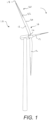
- FIG. 1 is a schematic perspective view of a modern utility-scale wind turbine 10.
- the wind turbine 10 comprises a plurality of wind turbine blades 12 that extend from a root 14 in an inboard portion 16 of the blade 12, to a tip 18 in an outboard portion 20 of the blade 12.
- Each wind turbine blade 12 comprises an erosion shield 22 arranged at a leading edge 24 of the blade 12.
- the erosion shield 22 is arranged in the outboard potion 20 of the blade 12 in this example, the invention is not limited in this respect and an erosion shield 22 may be arranged in the inboard portion 16 or extending along substantially the entire leading edge 24 of a turbine blade 12.
- the erosion shield 22 provides protection for the leading edge 24 in use where collisions between the blade 12 and airborne particles such as rain and hail cause erosion. Such erosion would otherwise adversely affect the aerodynamic performance of the blade 12 and thereby reduce annual energy production (AEP) of the wind turbine 10. In some cases, leading edge erosion can result in AEP losses of up to 5%.
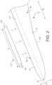
- FIG. 2 is a schematic perspective view of a portion of a wind turbine blade 12 and an erosion shield 22.
- the blade 12 comprises a blade shell 26 which may be made from composite material, e.g. glass fibre reinforced plastic (GFRP), and manufactured using methods known in the art such as lamination of composite layers in a resin matrix.
- GFRP glass fibre reinforced plastic
- the blade shell 26 has an aerodynamic profile and extends in a spanwise direction (S) between the blade root 14 and the tip 18 of the blade 12, and in a chordwise direction (C) between the leading edge 24 and a trailing edge 28 of the blade 12.
- a leading edge region 30 is defined by the leading edge 24 and extends along substantially the entire spanwise length of the leading edge 24.
- the leading edge region 30 spans the leading edge 24 of the blade 12 and comprises a portion of the blade shell 26 immediately adjacent the leading edge 24 on windward and leeward sides 32, 34 of the blade 12.
- the leading edge region 30 extends from the leading edge 24 by substantially equal amounts in the chordwise direction (C) on each of the windward and leeward sides 32, 34 of the blade 12.
- the erosion shield 22 is a so called 'softshell' shield and is formed of a sufficiently flexible material to allow the shield 22 to conform to the contour of the leading edge region 30 of the blade shell 26.
- the erosion shield 22 is made of a polymer material, such as a polyurethane material for example.
- the erosion shield 22 is elongate and comprises a substantially U-shaped profile.
- the erosion shield 22 is pre-formed into said U-shaped profile to approximate the profile of the blade shell 26 in the leading edge region 30.
- the erosion shield 22 comprises a substantially uniform cross-sectional profile throughout its longitudinal length L.
- the erosion shield 22 may not be pre-formed.
- the erosion shield 22 may be a substantially planar component having sufficient flexibility such that, when applied to a leading edge region 30 of a wind turbine blade 12, the planar shield 22 wraps around the leading edge 24 and assumes the profile of the blade shell 26 in the leading edge region 30.
- the erosion shield 22 comprises an inner surface 36 to be bonded to the leading edge region 30 of the blade shell 26, and an outer surface 38 which is exposed in use.
- the inner and outer surfaces 36, 38 are defined with respect to the configuration of said surfaces following application of the erosion shield 22 to the leading edge region 30 of the blade shell 26.
- the inner surface 36 is defined as the surface of the erosion shield 22 facing the leading edge region 30 of the blade shell 26 when the shield 22 is applied to the leading edge 30 of a wind turbine blade 12. It follows that the outer surface 38 is the surface that faces away from the blade shell 26, i.e. the outward facing surface 38 of the erosion shield 22 which is exposed to airborne particles such as rain and hail in use.
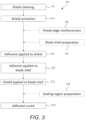
- Figure 3 is a flow chart 40 illustrating stages involved in the application of an erosion shield 22 to the leading edge region 30 of a wind turbine blade 12 in accordance with an example of the present method. Unless otherwise stated, it will be appreciated that the stages of the method may be performed in any suitable order and the invention is not limited to the specific order shown in Figure 3 .
- the method of applying the erosion shield 22 to the wind turbine blade 12 commences with preparation of the shield's inner surface 36 prior to application of adhesive. As will be described in more detail later, this preparation involves a cleaning stage 42 followed by an activation stage 44. In parallel with this, the blade shell 26 may be prepared 46. Wet adhesive is then applied to the shield 22, and further wet adhesive is applied to the blade shell in stages marked 48 and 50 respectively. The shield 22 is then applied to the blade shell 26 in the stage marked 52, to establish wet-to-wet surface contact between the shield 22 and the blade shell 26. The adhesive subsequently cures 54. These steps will now be discussed in detail, together with optional steps of the method, which are illustrated by the dashed-line boxes 46, 56 and 58 in Figure 3 . Applying the adhesive to each of the shield and the blade shell facilitate easy control of full covering of the surfaces and eventually wet-to-wet contact between the whole inner surface of the erosion shield and the blade shell.
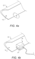
- Figure 4a is a schematic perspective view of an erosion shield 22 during the shield cleaning stage 42.
- the inner surface 36 of the shield 22 is cleaned using a solvent.
- the solvent used for cleaning the inner surface 36 is Isopropyl Alcohol (IPA).
- IPA Isopropyl Alcohol
- a lint free cloth 60 saturated in IPA may be used to clean the inner surface 36 of the erosion shield 22.
- the shield cleaning stage 42 of the present application method is influential in achieving sufficient adhesion between the erosion shield 22 and the leading edge region 30 of the blade shell 26. Any number of contaminants or foreign particles may be present on the inner surface 36 of the erosion shield 22 following the manufacture of said shield 22. Such contaminants or foreign particles significantly impact the adhesion of an erosion shield 22 to the leading edge region 30, and in use can lead to the shield 22 becoming detached from the wind turbine blade 12 prematurely.
- a release agent in the mould to facilitate removal of the shield 22 from the mould.
- Typical release agents include silicon-based release agents.
- the cleaning step 42 of the present method ensures that any contaminants or residuals, and in particular residual mould release agents, are removed from the shield 22. Cleaning the inner surface 36 of the erosion shield 22 can therefore be defined as the removal of residuals from the preparation of the erosion shield 22.
- Figure 4b shows a schematic perspective view of the shield activation stage 44 of the application method following the shield cleaning stage 42. After cleaning the inner surface 36 of the erosion shield 22 using a solvent, said inner surface 36 is activated. In the example shown in Figure 4b , activating the inner surface 36 comprises abrading said inner surface 36 to increase the surface roughness thereof.
- FIG. 5a shows a schematic perspective view of stages 48 and 50 of the application method wherein a layer of wet adhesive 66, 68 is applied to both the inner surface 36 of the erosion shield 22 and the leading edge region 30 of the blade shell 26 respectively.
- the wet adhesive 66 is applied to the erosion shield 22 such that substantially the entire inner surface 36 comprises a layer of wet adhesive 66.
- the adhesive 68 is applied to the leading edge region 30 of the blade shell 26 such that substantially an entire portion 70 of the leading edge region 30 to which the erosion shield 22 will be arranged comprises a layer of wet adhesive 68.
- Each of the inner surface 36 of the erosion shield 22 and the portion 70 of the leading edge region 30 of the blade shell 26 are wet-out in the application of the respective wet adhesive layers 66, 68, ensuring a consistent and thorough surface coverage is achieved.
- the wet adhesive layers 66, 68 are applied such that there is no surface-to-air contact on inner surface 36 of the erosion shield 22 and the leading edge region 30 of the blade shell 26.
- care is taken to ensure that the layer of adhesive 66, 68 on each of the shield inner surface 36 and the leading edge region 30 does not comprise air bubbles or other regions where adhesive is not present.
- the quality of the adhesive application may be quantified in that for each of the adhesive layers 66, 68, there may be a total area of less than 50 mm 2 , preferably less than 20 mm 2 , most preferably less than 10 mm 2 and optimally less than 1 mm 2 wherein there is air contact between the underlying inner surface 36 of the shield 22 or the blade shell 26.
- the adhesive 66, 68 is a liquid adhesive.
- the wet adhesive 66, 68 is preferably a two-part epoxy adhesive.
- Sikapower 1200, Locktite Hysol EA 9464 and Sikapower 1277 provide particularly advantageous results in terms of erosive wear of the erosion shield 22 and in terms of adhesion between said shield 22 and the blade shell 26.
- the wet adhesive layers 66, 68 therefore preferably comprise one of the above mentioned two-part epoxy adhesives.
- the selection of adhesive is critical to the performance of the erosion shield 22. It has been found that the above referenced adhesives offer optimal adhesion with complementary stiffness characteristics to dissipate the impact energy of incident airborne particles colliding with the erosion shield 22. Whilst an erosion shield 22 can aid in dissipating the impact energy of incident airborne particles, bonding the erosion shield 22 to the blade shell 26 using an adhesive having high stiffness can result in an erosive effect known as drumming, wherein some of the impact energy is transmitted through the adhesive layer 66, 68 and into the blade shell 26. Drumming can lead to delamination of the erosion shield 22 from the blade shell 26, or initiate early erosion of the shield 22, which may progress further to the blade shell 26.
- An adhesive having too low a stiffness can also cause drumming as the adhesive layer 66, 68 and erosion shield 22 do not absorb and dissipate enough of the impact energy. It is therefore important that an adhesive complementary to the erosion shield 22 in terms of adhesion and stiffness characteristics is applied to the shield's inner surface 36 and the blade shell 26.
- the method may further comprise a blade shell preparation stage 46 prior to applying the wet adhesive 68 to the leading edge region 30.
- the leading edge region 30 of the blade shell 26 is activated and said region 30 is subsequently cleaned using a solvent to remove any particles created during activation.
- the leading edge region 30 may be cleaned using Isopropyl Alcohol (IPA), and cleaning said region 30 may comprise using a lint free cloth saturated with IPA.
- IPA Isopropyl Alcohol
- Figure 5b is a schematic cross-sectional view of the stage of the application method marked 52, wherein the erosion shield 22 is applied to the blade shell 26 by arranging said shield 22 against the leading edge region 30.
- wet-to-wet adhesive contact it is meant that the wet adhesive 66 on the erosion shield 22 is brought into contact with the wet adhesive 68 on the blade shell 26.
- Wet-to-wet contact advantageously ensures that at least one layer of adhesive 66, 68 is present between the erosion shield 22 and blade shell 26 when the shield 22 is arranged against the leading edge region 30.
- this leads to that pores and air-pockets only may appear inside the adhesive and not at the interface between the blade shell 26 and the wet adhesive 68 on the blade shell or at the interface between the erosion shield and the wet adhesive 66 on the erosion shield.
- erosive wear as a result of drumming is particularly severe in 'dry spot' locations where no adhesive is present between the erosion shield 22 and blade shell 26.
- the wet-to-wet adhesive contact minimizes the effect of any small pores or air bubbles present in one of the adhesive layers 66, 68 as the adhesive in the other of the adhesive layers 68, 66 fills any such small pores or air pockets such that no dry spot locations exist.
- FIG. 5c shows the erosion shield 22 arranged against the leading edge region 30 of the blade shell 26 in a schematic cross-sectional view.
- the erosion shield 22 is pressed against the leading edge region 30 of the blade shell 26.
- the layer of wet adhesive 66 on the erosion shield's inner surface 36 and the layer of wet adhesive 68 on the leading edge region 30 combine to form a single homogenous layer of adhesive 72 between the erosion shield 22 and the blade shell 26. Air-pockets in or between the adhesive layers 66, 68 may be squeezed out from beneath the erosion shield 22 when pressing said shield 22 against the blade shell 26.
- some adhesive 72a may squeeze out from beneath the erosion shield 22.
- This adhesive 72a may be used to form a seal along a longitudinal edge 74 of the erosion shield 22 as described below with reference to Figures 7a to 7c .
- the stage of the application method marked 54 on Figure 3 comprises curing the adhesive 72 to bond the erosion shield 22 to the leading edge region 30 of the blade shell 26.
- curing it is meant that the adhesive 72 hardens to form an adhesive bond affixing the erosion shield 22 to the blade shell 26.
- the adhesive 72 may be cured by ambient temperatures following arrangement of the erosion shield 22 with the leading edge region 30. Alternatively, the adhesive 72 may be cured by the application heat, for example by means of a heating blanket arranged over the erosion shield 22.
- FIG. 6 is a schematic perspective view of an erosion shield 22 during a shield edge reinforcement stage 56 included in some examples of the application method.
- the shield edge reinforcement stage 56 comprises applying a length of removable reinforcing tape 76 along a longitudinal edge 74 of the erosion shield 22 prior to arranging the erosion shield 22 against the leading edge region 30.
- the removable reinforcing tape 76 is applied in order to temporarily increase the stiffness of a given longitudinal edge 74 of the erosion shield 22.
- the reinforcing tape 76 prevents the shield 22 from wrinkling e.g. by local deformation during application of the shield 22 to the blade shell 26 and during curing of the adhesive 72. Such wrinkles at the longitudinal edge 74 of a shield 22 could otherwise adversely affect the aerodynamic performance of the blade 12 to which the shield 22 is applied.
- the reinforcing tape 76 is removed after the adhesive 72 has cured and the erosion shield 22 is affixed to the leading edge region 30.
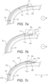
- Figure 7a is a schematic cross-sectional view of the blade shell 26 with an erosion shield 22 arranged against the leading edge region 30 following the stage of the method marked 52.
- some adhesive 72a may be squeezed from beneath the erosion shield 22 when arranging said shield 22 against the blade shell 26.
- said squeezed adhesive 72a is used to form a seal 78 along a longitudinal edge 74 of the erosion shield 22.
- a sealing region 80 of the blade shell 26 is defined adjacent to a longitudinal edge 74 of the erosion shield 22.
- the sealing region 80 extends in the spanwise direction (S) on the blade shell 26 along substantially the entire length of the longitudinal edge 74 of the erosion shield 22, perpendicular to the plane of the page on Figure 7a .
- the sealing region 80 is specifically defined between the longitudinal edge 80 and a length of removable tape (not shown) arranged on the blade shell 26. In such an example, the length of removable tape is arranged substantially parallel to, and spaced apart from, the longitudinal edge 74 of the erosion shield 22.
- Adhesive 72a is provided in the sealing region 80 of the blade shell 26.
- excess adhesive 66, 68 may be applied to the inner surface 36 of the erosion shield 22 and the leading edge region 30 of the blade shell 26.
- some adhesive 72a may be squeezed from between the shield's inner surface 36 and the leading edge region 30 and into the sealing region 80 upon arranging the erosion shield 22 against the blade shell 26.
- additional adhesive may be applied to the sealing region 80 following arrangement of the erosion shield 22.
- Figure 7b shows a further step in the sealing region preparation stage 58.
- the adhesive 72a in the sealing region 80 is shaped to form a smooth transition between the longitudinal edge 74 of the erosion shield 22 and the blade shell 26.
- the adhesive 72a in the sealing region 80 is shaped to form a smooth transition between the longitudinal edge 74 of the erosion shield 22 and the length of removable tape if used on the blade shell 26 to demarcate the sealing region 80.
- the adhesive 72a is shaped using a forming tool 82 to scrape the adhesive 72a along the sealing region 80 in the spanwise direction (S) to fill said sealing region 80 and provide a smooth outer surface 84 on the adhesive 72a.
- the dotted line on Figure 7b shows the adhesive 72a in the sealing region 80 prior to being shaped, illustrating the difference in profile of the adhesive 72a following shaping thereof for comparison.
- a sealant is applied to the longitudinal edge 74 of the erosion shield 22 in the sealing region 80. It has been found that the sealant erodes away relatively quickly in use, reducing aerodynamic performance of the blade 12.
- Providing adhesive 72a in the sealing region 80 is advantageous as the adhesive 72a has a greater resistance to erosive wear than a sealant.
- adhesive 72a squeezed from beneath the erosion shield 22 is provided in the sealing region 80, a more time-efficient method of applying an erosion shield 22 is facilitated, comprising fewer stages and materials than known methods.
- Figure 7c shows yet a further step in the sealing region preparation stage 58.
- Adhesive 72a in the sealing region 80 is covered by a length of removable tape 86 to maintain the shape of the adhesive 72a and the smooth transition between the erosion shield 22 and blade shell 26 during curing of said adhesive 72a.
- the outer surface 84 of the adhesive 72a is thereby protected during curing of the adhesive 72a, enabling a smooth outer surface 84 to be achieved even when applying the erosion shield 22 to the leading edge region 30 in poor weather conditions.
- the length of removable tape 86 is sufficiently transparent to enable inspection of the adhesive 72a in the sealing region 80 to ensure no air-pockets or other defects are present in the adhesive 72a in the sealing region 80.
- the length of removable tape 86 is removed to provide a smooth aerodynamic transition from the outer surface 38 of the erosion shield 22 to the blade shell 26.
- a UV resistant coating is applied to the outer surface 84 of the adhesive 72a after removing the length of tape 86.
- the UV resistant coating prolongs the lifetime of the adhesive 72a by blocking UV radiation in sunlight which could cause exposed adhesive to become brittle and susceptible to erosive wear.
- it was wound that using a combination of a non-UV resistant adhesive with a UV resistant coating applied to the sealing region provided better overall performance of the erosion shield as a better fit of properties of the adhesive was possible when using a non-UV resistant adhesive than if limited to UV resistant adhesives.
- the method may comprise an additional stage of applying a bagging film (not shown) over the erosion shield 22 and sealing region 80 after arranging the shield 22 with the leading edge region 30.
- the bagging film helps to hold the erosion shield 22 in position on the leading edge region 30 prior to the adhesive 72 curing.
- the bagging film may be temporarily secured to the blade shell 26 or the erosion shield 22 with removable tape or with a pressure sensitive adhesive on at least a part of the surface of the bagging film connected to the blade shell 26 or the erosion shield 22.
- a roller may be used to squeeze adhesive 72 and air-pockets out from beneath the inner surface 36 of the erosion shield 22.
- Adhesive 72 from between the erosion shield 22 and leading edge region 30 may thereby be provided in the sealing region 80.
- use of the bagging film prevents any transfer of adhesive 72a from the sealing region 80 to the roller as the wet adhesive 72a is contained beneath the bagging film.
- the roller may therefore be used to thoroughly smooth the erosion shield 22 against the leading edge region 30, rolling in the chordwise direction (C) from a leading edge 88 of the shield 22 up to and beyond a respective longitudinal edge 74, and over the sealing region 80 without picking up adhesive 72a and transferring it to the outer surface 38 of the erosion shield 22.
- the bagging film is removed.
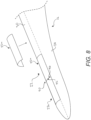
- FIG 8 is a schematic perspective view of a wind turbine blade 12 during application of an erosion shield 22 in accordance with another example of the method.
- the erosion shield 22 comprises a plurality of longitudinally-extending shield sections 22a.
- the method further comprises arranging the shield sections 22a adjacent one another against the leading edge region 30 of the blade shell 26.
- the shield sections 22a are arranged such that a butt joint 90 is formed between adjacent edges 92, 94 of adjacent shield sections 22a.
- the adjacent edges 92, 94 of adjacent shield sections 22a do not overlap. It has been found that erosive wear of an erosion shield as a result of drumming is particularly severe in overlapping regions of adjacent shield sections of known leading edge protection methods.
- adhesive may be applied between overlapping potions, resulting in a sandwich structure of adhesive layers and erosion shield material at an interface between adjacent shield sections.
- the impact energy of airborne particles incident on the leading edge region of the blade shell is dissipated less effectively due to the increased rigidity in such a region of the erosion shield, resultant from the additional adhesive and shield material layers.
- the present application method comprising the formation of a butt joint 90 between adjacent shield sections 22a, therefore provides an improved leading edge protection solution.
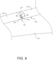
- Figure 9 is a schematic perspective view of a further stage in the application method comprising arranging a plurality of shield sections 22a adjacent one another. Preferably there is no gap between the adjacent edges 92, 94 of adjacent shield sections 22a after forming the butt joint 90. In practice a small gap of less than 2 mm, preferably less than 1 mm, and most preferably less than 0.5 mm may be present between adjacent edges 92, 94 of adjacent shield sections 22a.
- Adhesive 96 is provided to the butt joint 90 between adjacent edges 92, 94 of adjacent shield sections 22a. Said adhesive 96 may be provided as the shield sections 22a are arranged against the leading edge region 30 of the blade shell 26 if excess adhesive from beneath the shield sections 22a is squeezed into the butt joint 90. Alternatively, the adhesive 96 could be provided by applying additional adhesive between the adjacent edges 92, 94 following arrangement of the shield sections 22a.
- the adhesive 96 in the butt joint 90 may be shaped by scraping away any excess adhesive to provide a smooth outer surface 98.
- the adhesive 96 in the butt joint 90 is covered with a strip of removable tape 100 to maintain the shape of the adhesive 96 during curing thereof.
- the tape 100 further helps to protect the adhesive 96 in the butt joint 90 during curing.
- the strip of tape is removed to provide a smooth aerodynamic transition between the adjacent shield sections 22a.
- the method may further comprise applying a UV resistant coating to the outer surface 98 of the adhesive 96 in the butt joint 90.
- the above described method provides an improved method of applying an erosion shield to a wind turbine blade.
- the method provides a solution in which adhesion between the erosion shield and the blade shell is increased such that a durable solution to leading edge protection can be achieved.
- the erosion shield is capable of protecting the leading edge of the wind turbine blade for its entire projected use-period or significantly longer than present methods without delaminating from the blade in an early stage of use, thereby enabling effective protection of the leading edge from erosion.
Landscapes
- Engineering & Computer Science (AREA)
- Mechanical Engineering (AREA)
- Chemical & Material Sciences (AREA)
- Chemical Kinetics & Catalysis (AREA)
- General Chemical & Material Sciences (AREA)
- Life Sciences & Earth Sciences (AREA)
- Sustainable Development (AREA)
- Sustainable Energy (AREA)
- Combustion & Propulsion (AREA)
- General Engineering & Computer Science (AREA)
- Physics & Mathematics (AREA)
- Fluid Mechanics (AREA)
- Turbine Rotor Nozzle Sealing (AREA)
- Wind Motors (AREA)
Description
- The present invention relates generally to wind turbine blades and more specifically to a method of protecting a leading edge of a wind turbine blade.
- Wind turbines frequently experience severe weather conditions due to their remote location, particularly in offshore wind installations. Collisions between a wind turbine blade and airborne particles such as rain or hail cause erosion of the blade's surface. Such erosion reduces the blade's smoothness and aerodynamic performance, thereby adversely affecting the annual energy production (AEP) of the wind turbine. As blade lengths increase to capture more energy from the wind, the tip velocity of such blades also increases. At high tip velocities, erosion of the blade surface, particularly at a leading edge of the blade, is exacerbated by the increased impact energy in collisions with airborne particles.
- A number of solutions to alleviate leading edge erosion have previously been proposed, including the application of tape, paint, protective coatings or metal shields to the leading edge. A particularly effective solution is the application of a polymer-based protective cover, for example as described in
WO2016075619 . In practice, such covers are fixed to the leading edge of a blade using a double-sided adhesive tape. However, it has been found that existing methods for affixing such protective covers to the leading edge of a blade are not sufficiently durable and do not have the requisite longevity. In particular, it has been found that protective covers have a tendency to delaminate from the wind turbine blade in an early stage of their projected use-period, thereby leaving the leading edge exposed to erosion. The protective cover may therefore have a limited lifetime in comparison to the projected lifetime of a wind turbine blade. -
WO2019048014 A1 describes a method of preparing a protective shell and mounting on a wind turbine blade. - It is against this background that the present invention has been developed.
- In a first aspect of the invention there is provided a method according to
claim 1 of applying an erosion shield to a leading edge region of a wind turbine blade. The method comprises providing a wind turbine blade comprising a blade shell having an aerodynamic profile and defining a leading edge region; providing an erosion shield made of a polymer material, the erosion shield having an inner surface to be bonded to the leading edge region of the blade shell, and an outer surface to be exposed in use; activating the inner surface of the erosion shield, and cleaning the inner surface of the erosion shield using a solvent. Preferably, cleaning the inner surface of the erosion shield is performed after activating the inner surface of the erosion shield but cleaning may also be conducted before activating or both before and after activating the inner surface of the erosion shield. The method further comprises applying a layer of wet adhesive to the inner surface of the erosion shield; applying a layer of wet adhesive to the leading edge region of the blade shell; arranging the erosion shield against the leading edge region of the blade shell such that wet-to-wet adhesive contact is established between the inner surface of the erosion shield and the blade shell, and curing the adhesive to bond the erosion shield to the leading edge region of the blade shell. - Activating the inner surface of the erosion shield may comprise abrading said inner surface. The inner surface of the erosion shield may be activated using an abrasive having a grit rating of between 50 and 200, preferably 60 to 120 and more preferably 120. The abrasive may for example be a sanding paper, sanding abrasive mesh or another abrading media. Preferred abrasive is sanding abrasive mesh such as Autonet 120. The inner surface of the erosion shield may be activated by using an orbital sander comprising an abrasive such as Autonet 120. The inner surface of the erosion shield may be cleaned using Isopropyl Alcohol (IPA) or another suitable solvent . A lint free cloth may be used with the IPA or solvent to clean the inner surface of the erosion shield before or after activating the inner surface.
- It was found to be highly advantageous that wet-to-wet adhesive contact is established between the whole inner surface of the erosion shield and the blade shell. Particularly, establishing wet-to-wet adhesive contact in only a part of the contact was found to create points that over time may lead to local degradation of the erosion shield or of the adhesive.
- Prior to applying the wet adhesive to the leading edge region of the blade shell, the method may comprise activating the leading edge region and cleaning the leading edge region using a solvent. Preferably cleaning the leading edge region is performed after activating the leading edge region, but cleaning may also be conducted before activating or both before and after activating the leading edge region. The leading edge region of the blade shell may be cleaned using Isopropyl Alcohol (IPA). A lint free cloth may be used with the IPA to clean the leading edge region.
- The adhesive may be a two-part epoxy adhesive. Preferably the two-part epoxy adhesive may be one of Sikapower 1200, Locktite Hysol EA 9464, or Sikapower 1277.
- Prior to arranging the erosion shield against the leading edge region of the blade shell, the method further comprises applying a length of removable reinforcing tape along a longitudinal edge of the erosion shield to increase the stiffness of said longitudinal edge temporarily during arrangement of the erosion shield and curing of the adhesive. It was found that this reduced the tendency to create wrinkles along the longitudinal edge during arranging of the erosion shield against the leading edge region on the blade shell. Particularly, if adhesive and air is forced towards the longitudinal edge during arranging of the erosion shield for example with a roller or an outer mould part, the erosion shield may deform and create wrinkles along the longitudinal edge, and this may be reduced if the longitudinal edge of the erosion shield is reinforced by a removable tape.
- The method may further comprise providing adhesive in a sealing region of the blade shell, the sealing region being defined adjacent to a longitudinal edge of the erosion shield, and shaping the adhesive such that said adhesive forms a smooth transition between the longitudinal edge of the erosion shield and the blade shell. Further, the method may comprise covering the adhesive in the sealing region with a length of removable tape to maintain the shape of the adhesive and smooth transition between the erosion shield and blade shell during curing of said adhesive in the sealing region. Following curing of the adhesive in the sealing region, the length of removable tape may be removed to provide a smooth aerodynamic transition from the outer surface of the erosion shield to the blade shell.
- A UV resistant coating may be applied to an outer surface of the adhesive in the sealing region after removing the length of removable tape.
- After arranging the erosion shield against the leading edge region of the blade shell, the method may further comprise arranging a bagging film over the erosion shield and/or sealing region, and using a roller to smooth the erosion shield against the leading edge region, squeezing adhesive and air-pockets out from between the inner surface of the erosion shield and the blade shell. The bagging film may be temporarily secured to the blade shell using removable tape. The bagging film may prevent that the erosion shield shifts on the blade shell during and after adhesive and air-pockets are squeezed from between the inner surface of the erosion shield and the blade shell. The bagging film may also prevent that the outer surface of the erosion shield is contaminated by adhesive via the roller. The bagging film may for example be a vacuum bag film material or another transparent sheet material that allows for positioning over the erosion shield without forming of wrinkles.
- The erosion shield may be made of a polyurethane material. The erosion shield may have sufficient flexibility such that it conforms to the contour of the leading edge region of the blade shell. Preferably the erosion shield may be a softshell erosion shield. Further, the erosion shield may be elongate and comprise a substantially U-shaped profile. The erosion shield may comprise a substantially uniform cross-sectional profile throughout its longitudinal length.
- The erosion shield may comprise a plurality of longitudinally-extending shield sections, and the method may further comprise arranging the shield sections adjacent one another along the leading edge region of the blade shell and forming a butt joint between said adjacent shield sections such that adjacent edges of the adjacent shield sections do not overlap.
- The method may further comprise providing adhesive to the butt joint between adjacent edges of adjacent shield sections, covering the adhesive in the butt joint between adjacent shield sections with a strip of removable tape to maintain the shape of the adhesive during curing thereof, and removing said strip of removable tape following curing of the adhesive in the butt joint to provide a smooth aerodynamic transition between the adjacent shield sections. The method may further comprise applying a UV resistant coating to an outer surface of the adhesive in the butt joint following removal of the strip of removable tape.
- The present invention will now be described in further detail, by way of nonlimiting example only, with reference to the following figures, in which:
-
Figure 1 is a schematic perspective view of a wind turbine; -
Figure 2 is a schematic perspective view of a portion of a wind turbine blade and an erosion shield; -
Figure 3 is a flow chart illustrating stages involved in a method of applying an erosion shield to a leading edge region; -
Figures 4a and 4b schematically show the shield being prepared prior to bonding to the blade, in whichFigure 4a shows a surface of the shield being cleaned, andFigure 4b shows the surface being activated; -
Figure 5a schematically shows adhesive applied to the erosion shield and to the blade; -
Figures 5b and 5c are schematic cross-sectional views of the erosion shield arranged against the blade; -
Figure 6 schematically shows a length of reinforcing tape being applied to an edge of the erosion shield; -
Figures 7a to 7c are schematic cross-sectional views of a sealing region preparation stage of the method, in whichFigure 7a shows adhesive in the sealing region,Figure 7b shows a stage wherein the adhesive in the sealing region is shaped, andFigure 7c shows a length of removable tape applied over the adhesive in the sealing region; -
Figure 8 is a schematic perspective view of a wind turbine blade during application of an erosion shield comprising a plurality of shield sections; and -
Figure 9 is a further schematic perspective view of the wind turbine blade during application of the erosion shield comprising a plurality of shield sections. -
Figure 1 is a schematic perspective view of a modern utility-scale wind turbine 10. The wind turbine 10 comprises a plurality ofwind turbine blades 12 that extend from aroot 14 in aninboard portion 16 of theblade 12, to atip 18 in anoutboard portion 20 of theblade 12. Eachwind turbine blade 12 comprises anerosion shield 22 arranged at aleading edge 24 of theblade 12. Although theerosion shield 22 is arranged in theoutboard potion 20 of theblade 12 in this example, the invention is not limited in this respect and anerosion shield 22 may be arranged in theinboard portion 16 or extending along substantially the entire leadingedge 24 of aturbine blade 12. - The
erosion shield 22 provides protection for theleading edge 24 in use where collisions between theblade 12 and airborne particles such as rain and hail cause erosion. Such erosion would otherwise adversely affect the aerodynamic performance of theblade 12 and thereby reduce annual energy production (AEP) of the wind turbine 10. In some cases, leading edge erosion can result in AEP losses of up to 5%. -
Figure 2 is a schematic perspective view of a portion of awind turbine blade 12 and anerosion shield 22. Theblade 12 comprises ablade shell 26 which may be made from composite material, e.g. glass fibre reinforced plastic (GFRP), and manufactured using methods known in the art such as lamination of composite layers in a resin matrix. Theblade shell 26 has an aerodynamic profile and extends in a spanwise direction (S) between theblade root 14 and thetip 18 of theblade 12, and in a chordwise direction (C) between theleading edge 24 and a trailingedge 28 of theblade 12. - A
leading edge region 30 is defined by the leadingedge 24 and extends along substantially the entire spanwise length of the leadingedge 24. Theleading edge region 30 spans the leadingedge 24 of theblade 12 and comprises a portion of theblade shell 26 immediately adjacent the leadingedge 24 on windward andleeward sides 32, 34 of theblade 12. In the example ofFigure 2 , theleading edge region 30 extends from the leadingedge 24 by substantially equal amounts in the chordwise direction (C) on each of the windward andleeward sides 32, 34 of theblade 12. - In this example, the
erosion shield 22 is a so called 'softshell' shield and is formed of a sufficiently flexible material to allow theshield 22 to conform to the contour of theleading edge region 30 of theblade shell 26. To offer optimal flexibility for fitting theshield 22 to ablade 12, as well as optimal wear resistant properties, theerosion shield 22 is made of a polymer material, such as a polyurethane material for example. - The
erosion shield 22 is elongate and comprises a substantially U-shaped profile. Theerosion shield 22 is pre-formed into said U-shaped profile to approximate the profile of theblade shell 26 in theleading edge region 30. In this example, theerosion shield 22 comprises a substantially uniform cross-sectional profile throughout its longitudinal length L. In other examples, theerosion shield 22 may not be pre-formed. For example, theerosion shield 22 may be a substantially planar component having sufficient flexibility such that, when applied to aleading edge region 30 of awind turbine blade 12, theplanar shield 22 wraps around the leadingedge 24 and assumes the profile of theblade shell 26 in theleading edge region 30. - The
erosion shield 22 comprises aninner surface 36 to be bonded to theleading edge region 30 of theblade shell 26, and anouter surface 38 which is exposed in use. The inner andouter surfaces erosion shield 22 to theleading edge region 30 of theblade shell 26. Theinner surface 36 is defined as the surface of theerosion shield 22 facing theleading edge region 30 of theblade shell 26 when theshield 22 is applied to the leadingedge 30 of awind turbine blade 12. It follows that theouter surface 38 is the surface that faces away from theblade shell 26, i.e. the outward facingsurface 38 of theerosion shield 22 which is exposed to airborne particles such as rain and hail in use. - Known methods of affixing erosion shields 22 to the
leading edge region 30 of awind turbine blade 12 do not achieve a sufficiently durable bond between saidshield 22 and thewind turbine blade 12. In use, delamination of anerosion shield 22 from awind turbine blade 12 is common, because the adhesive bond between theerosion shield 22 andblade shell 26 fails far sooner than the projected lifetime of theshield 22. As will now be described by way of example with reference toFigures 3 to 9 , the present invention provides an improved method of applying anerosion shield 22 to theleading edge region 30 of awind turbine blade 12. -
Figure 3 is aflow chart 40 illustrating stages involved in the application of anerosion shield 22 to theleading edge region 30 of awind turbine blade 12 in accordance with an example of the present method. Unless otherwise stated, it will be appreciated that the stages of the method may be performed in any suitable order and the invention is not limited to the specific order shown inFigure 3 . - Referring to
Figure 3 , the method of applying theerosion shield 22 to thewind turbine blade 12 commences with preparation of the shield'sinner surface 36 prior to application of adhesive. As will be described in more detail later, this preparation involves acleaning stage 42 followed by anactivation stage 44. In parallel with this, theblade shell 26 may be prepared 46. Wet adhesive is then applied to theshield 22, and further wet adhesive is applied to the blade shell in stages marked 48 and 50 respectively. Theshield 22 is then applied to theblade shell 26 in the stage marked 52, to establish wet-to-wet surface contact between theshield 22 and theblade shell 26. The adhesive subsequentlycures 54. These steps will now be discussed in detail, together with optional steps of the method, which are illustrated by the dashed-line boxes Figure 3 . Applying the adhesive to each of the shield and the blade shell facilitate easy control of full covering of the surfaces and eventually wet-to-wet contact between the whole inner surface of the erosion shield and the blade shell. -
Figure 4a is a schematic perspective view of anerosion shield 22 during theshield cleaning stage 42. Theinner surface 36 of theshield 22 is cleaned using a solvent. In this example, the solvent used for cleaning theinner surface 36 is Isopropyl Alcohol (IPA). As shown inFigure 4a , a lintfree cloth 60 saturated in IPA may be used to clean theinner surface 36 of theerosion shield 22. - The
shield cleaning stage 42 of the present application method is influential in achieving sufficient adhesion between theerosion shield 22 and theleading edge region 30 of theblade shell 26. Any number of contaminants or foreign particles may be present on theinner surface 36 of theerosion shield 22 following the manufacture of saidshield 22. Such contaminants or foreign particles significantly impact the adhesion of anerosion shield 22 to theleading edge region 30, and in use can lead to theshield 22 becoming detached from thewind turbine blade 12 prematurely. - In the case of moulded polymer erosion shields 22, it is common practice to use a release agent in the mould to facilitate removal of the
shield 22 from the mould. Typical release agents include silicon-based release agents. However, it has been found that residuals of these release agents tend to remain on thesurface 36 of theshield 22 and impair the adhesion between theshield 22 and theblade shell 26. The cleaningstep 42 of the present method ensures that any contaminants or residuals, and in particular residual mould release agents, are removed from theshield 22. Cleaning theinner surface 36 of theerosion shield 22 can therefore be defined as the removal of residuals from the preparation of theerosion shield 22. -
Figure 4b shows a schematic perspective view of theshield activation stage 44 of the application method following theshield cleaning stage 42. After cleaning theinner surface 36 of theerosion shield 22 using a solvent, saidinner surface 36 is activated. In the example shown inFigure 4b , activating theinner surface 36 comprises abrading saidinner surface 36 to increase the surface roughness thereof. - Thorough experimentation comprising activation of the
inner surface 36 using abrasives having a wide range of grit ratings revealed that activating theinner surface 36 using an abrasive 62 having a grit rating of between 100 and 200 provides particularly advantageous adhesion between theerosion shield 22 and theblade shell 26. It has been found that optimal adhesion is achieved when activation of theinner surface 36 comprises abrading saidsurface 36 using an abrasive 62 having a grit rating of 120, such as Autonet 120. As shown inFigure 4b , anorbital sander 64 comprising an abrasive 62 such as Autonet 120 may be used to activate theinner surface 36 by abrasion. - Conducting the cleaning and activation stages 42, 44 in the order described above (i.e. cleaning before activating) leads to the surprising effect that the adhesion between an
erosion shield 22 and theleading edge region 30 of awind turbine blade 12 is significantly increased. Known methods for applying anerosion shield 22 to ablade shell 26 do not conventionally comprise cleaning theinner surface 36 of saiderosion shield 22 prior to activation thereof. In known methods where a cleaning stage does occur, this is commonly included to clean any particles created during an activation stage if such a stage is also implemented. - If the
inner surface 36 of theerosion shield 22 is not cleaned prior to activation, contaminants or residuals of release agents may be spread or become embedded in thesurface 36 duringactivation 44, such that a subsequent cleaning stage would not remove said contaminants or residuals of release agents. Conducting the cleaning and activation stages 42, 44 in the above described order therefore advantageously provides increased adhesion between theerosion shield 22 andblade shell 26 in comparison to existing methods. -
Figure 5a shows a schematic perspective view ofstages wet adhesive inner surface 36 of theerosion shield 22 and theleading edge region 30 of theblade shell 26 respectively. Instage 48, thewet adhesive 66 is applied to theerosion shield 22 such that substantially the entireinner surface 36 comprises a layer ofwet adhesive 66. Similarly, instage 50 the adhesive 68 is applied to theleading edge region 30 of theblade shell 26 such that substantially anentire portion 70 of theleading edge region 30 to which theerosion shield 22 will be arranged comprises a layer ofwet adhesive 68. Each of theinner surface 36 of theerosion shield 22 and theportion 70 of theleading edge region 30 of theblade shell 26 are wet-out in the application of the respective wetadhesive layers - Preferably, the wet
adhesive layers inner surface 36 of theerosion shield 22 and theleading edge region 30 of theblade shell 26. In applying the adhesive 66, 68, care is taken to ensure that the layer of adhesive 66, 68 on each of the shieldinner surface 36 and theleading edge region 30 does not comprise air bubbles or other regions where adhesive is not present. The quality of the adhesive application may be quantified in that for each of theadhesive layers inner surface 36 of theshield 22 or theblade shell 26. - By 'wet adhesive' it will be understood that the adhesive 66, 68 is a liquid adhesive. The
wet adhesive erosion shield 22 and in terms of adhesion between saidshield 22 and theblade shell 26. The wetadhesive layers - The selection of adhesive is critical to the performance of the
erosion shield 22. It has been found that the above referenced adhesives offer optimal adhesion with complementary stiffness characteristics to dissipate the impact energy of incident airborne particles colliding with theerosion shield 22. Whilst anerosion shield 22 can aid in dissipating the impact energy of incident airborne particles, bonding theerosion shield 22 to theblade shell 26 using an adhesive having high stiffness can result in an erosive effect known as drumming, wherein some of the impact energy is transmitted through theadhesive layer blade shell 26. Drumming can lead to delamination of theerosion shield 22 from theblade shell 26, or initiate early erosion of theshield 22, which may progress further to theblade shell 26. - An adhesive having too low a stiffness can also cause drumming as the
adhesive layer erosion shield 22 do not absorb and dissipate enough of the impact energy. It is therefore important that an adhesive complementary to theerosion shield 22 in terms of adhesion and stiffness characteristics is applied to the shield'sinner surface 36 and theblade shell 26. - It has been found that a synergistic effect lies in the above described
stages inner surface 36 of theerosion shield 22 in the manner described above, first cleaning 42 and then activating 44 saidsurface 36, and by applying a layer ofwet adhesive erosion shield 22 and theblade shell 26, adhesion between theerosion shield 22 and theblade shell 26 is greatly improved whilst erosive wear as a result of drumming is dramatically reduced. - In some examples, the method may further comprise a blade
shell preparation stage 46 prior to applying the wet adhesive 68 to theleading edge region 30. Theleading edge region 30 of theblade shell 26 is activated and saidregion 30 is subsequently cleaned using a solvent to remove any particles created during activation. Theleading edge region 30 may be cleaned using Isopropyl Alcohol (IPA), and cleaning saidregion 30 may comprise using a lint free cloth saturated with IPA. -
Figure 5b is a schematic cross-sectional view of the stage of the application method marked 52, wherein theerosion shield 22 is applied to theblade shell 26 by arranging saidshield 22 against the leadingedge region 30. Theerosion shield 22, comprising a layer of wet adhesive 66 on theinner surface 36, is arranged with theleading edge region 30, also comprising a layer ofwet adhesive 68, such that wet-to-wet adhesive contact is established between theinner surface 36 of theerosion shield 22 and theblade shell 26. - By wet-to-wet adhesive contact, it is meant that the
wet adhesive 66 on theerosion shield 22 is brought into contact with thewet adhesive 68 on theblade shell 26. Wet-to-wet contact advantageously ensures that at least one layer of adhesive 66, 68 is present between theerosion shield 22 andblade shell 26 when theshield 22 is arranged against the leadingedge region 30. Preferably, this leads to that pores and air-pockets only may appear inside the adhesive and not at the interface between theblade shell 26 and thewet adhesive 68 on the blade shell or at the interface between the erosion shield and thewet adhesive 66 on the erosion shield. In some existing methods, erosive wear as a result of drumming is particularly severe in 'dry spot' locations where no adhesive is present between theerosion shield 22 andblade shell 26. The wet-to-wet adhesive contact minimizes the effect of any small pores or air bubbles present in one of theadhesive layers adhesive layers -
Figure 5c shows theerosion shield 22 arranged against the leadingedge region 30 of theblade shell 26 in a schematic cross-sectional view. After the wet-to-wet adhesive contact is established, as shown inFigure 5b , theerosion shield 22 is pressed against the leadingedge region 30 of theblade shell 26. The layer of wet adhesive 66 on the erosion shield'sinner surface 36 and the layer of wet adhesive 68 on theleading edge region 30 combine to form a single homogenous layer of adhesive 72 between theerosion shield 22 and theblade shell 26. Air-pockets in or between theadhesive layers erosion shield 22 when pressing saidshield 22 against theblade shell 26. In pressing theshield 22 against theblade shell 26, some adhesive 72a may squeeze out from beneath theerosion shield 22. This adhesive 72a may be used to form a seal along alongitudinal edge 74 of theerosion shield 22 as described below with reference toFigures 7a to 7c . - By applying
adhesive erosion shield 22 and theblade shell 26, and pressing these together such that a singlehomogenous adhesive layer 72 is formed between substantially the entireinner surface 36 of theerosion shield 22 and theblade shell 26, the occurrence of dry spots is minimized. As such, erosive wear as a result of drumming, which as discussed above is particularly severe in dry spot locations, is also minimized. The previously described synergistic effect in preparing theshield 22 for bonding by cleaning 42 and then activating 44, and applying a wetadhesive layer inner surface 36 and theleading edge region 30, both significantly increases adhesion between theshield 22 andblade shell 26, and reduces the effect of drumming. This results in a far more durable leading edge protection solution than other known methods. - The stage of the application method marked 54 on
Figure 3 comprises curing the adhesive 72 to bond theerosion shield 22 to theleading edge region 30 of theblade shell 26. By 'curing' it is meant that the adhesive 72 hardens to form an adhesive bond affixing theerosion shield 22 to theblade shell 26. The adhesive 72 may be cured by ambient temperatures following arrangement of theerosion shield 22 with theleading edge region 30. Alternatively, the adhesive 72 may be cured by the application heat, for example by means of a heating blanket arranged over theerosion shield 22. -
Figure 6 is a schematic perspective view of anerosion shield 22 during a shieldedge reinforcement stage 56 included in some examples of the application method. The shieldedge reinforcement stage 56 comprises applying a length of removable reinforcingtape 76 along alongitudinal edge 74 of theerosion shield 22 prior to arranging theerosion shield 22 against the leadingedge region 30. The removable reinforcingtape 76 is applied in order to temporarily increase the stiffness of a givenlongitudinal edge 74 of theerosion shield 22. The reinforcingtape 76 prevents theshield 22 from wrinkling e.g. by local deformation during application of theshield 22 to theblade shell 26 and during curing of the adhesive 72. Such wrinkles at thelongitudinal edge 74 of ashield 22 could otherwise adversely affect the aerodynamic performance of theblade 12 to which theshield 22 is applied. The reinforcingtape 76 is removed after the adhesive 72 has cured and theerosion shield 22 is affixed to theleading edge region 30. -
Figure 7a is a schematic cross-sectional view of theblade shell 26 with anerosion shield 22 arranged against the leadingedge region 30 following the stage of the method marked 52. As briefly discussed above with reference toFigure 5c , some adhesive 72a may be squeezed from beneath theerosion shield 22 when arranging saidshield 22 against theblade shell 26. There now follows a refinement to the method, wherein said squeezed adhesive 72a is used to form aseal 78 along alongitudinal edge 74 of theerosion shield 22. - As indicated by
reference numeral 80 onFigure 7a , a sealingregion 80 of theblade shell 26 is defined adjacent to alongitudinal edge 74 of theerosion shield 22. The sealingregion 80 extends in the spanwise direction (S) on theblade shell 26 along substantially the entire length of thelongitudinal edge 74 of theerosion shield 22, perpendicular to the plane of the page onFigure 7a . In some examples, the sealingregion 80 is specifically defined between thelongitudinal edge 80 and a length of removable tape (not shown) arranged on theblade shell 26. In such an example, the length of removable tape is arranged substantially parallel to, and spaced apart from, thelongitudinal edge 74 of theerosion shield 22. -
Adhesive 72a is provided in the sealingregion 80 of theblade shell 26. In some examples,excess adhesive inner surface 36 of theerosion shield 22 and theleading edge region 30 of theblade shell 26. In such an example, some adhesive 72a may be squeezed from between the shield'sinner surface 36 and theleading edge region 30 and into the sealingregion 80 upon arranging theerosion shield 22 against theblade shell 26. Alternatively, additional adhesive may be applied to the sealingregion 80 following arrangement of theerosion shield 22. -
Figure 7b shows a further step in the sealingregion preparation stage 58. The adhesive 72a in the sealingregion 80 is shaped to form a smooth transition between thelongitudinal edge 74 of theerosion shield 22 and theblade shell 26. Alternatively, the adhesive 72a in the sealingregion 80 is shaped to form a smooth transition between thelongitudinal edge 74 of theerosion shield 22 and the length of removable tape if used on theblade shell 26 to demarcate the sealingregion 80. The adhesive 72a is shaped using a formingtool 82 to scrape the adhesive 72a along the sealingregion 80 in the spanwise direction (S) to fill said sealingregion 80 and provide a smoothouter surface 84 on the adhesive 72a. The dotted line onFigure 7b shows the adhesive 72a in the sealingregion 80 prior to being shaped, illustrating the difference in profile of the adhesive 72a following shaping thereof for comparison. - In some known methods, a sealant is applied to the
longitudinal edge 74 of theerosion shield 22 in the sealingregion 80. It has been found that the sealant erodes away relatively quickly in use, reducing aerodynamic performance of theblade 12. Providing adhesive 72a in the sealingregion 80 is advantageous as the adhesive 72a has a greater resistance to erosive wear than a sealant. In examples where adhesive 72a squeezed from beneath theerosion shield 22 is provided in the sealingregion 80, a more time-efficient method of applying anerosion shield 22 is facilitated, comprising fewer stages and materials than known methods. -
Figure 7c shows yet a further step in the sealingregion preparation stage 58.Adhesive 72a in the sealingregion 80 is covered by a length ofremovable tape 86 to maintain the shape of the adhesive 72a and the smooth transition between theerosion shield 22 andblade shell 26 during curing of said adhesive 72a. Theouter surface 84 of the adhesive 72a is thereby protected during curing of the adhesive 72a, enabling a smoothouter surface 84 to be achieved even when applying theerosion shield 22 to theleading edge region 30 in poor weather conditions. - In some examples, the length of
removable tape 86 is sufficiently transparent to enable inspection of the adhesive 72a in the sealingregion 80 to ensure no air-pockets or other defects are present in the adhesive 72a in the sealingregion 80. - After the adhesive 72a in the sealing
region 80 has cured, the length ofremovable tape 86 is removed to provide a smooth aerodynamic transition from theouter surface 38 of theerosion shield 22 to theblade shell 26. In some examples, a UV resistant coating is applied to theouter surface 84 of the adhesive 72a after removing the length oftape 86. The UV resistant coating prolongs the lifetime of the adhesive 72a by blocking UV radiation in sunlight which could cause exposed adhesive to become brittle and susceptible to erosive wear. Surprisingly, it was wound that using a combination of a non-UV resistant adhesive with a UV resistant coating applied to the sealing region provided better overall performance of the erosion shield as a better fit of properties of the adhesive was possible when using a non-UV resistant adhesive than if limited to UV resistant adhesives. - In some examples, the method may comprise an additional stage of applying a bagging film (not shown) over the
erosion shield 22 and sealingregion 80 after arranging theshield 22 with theleading edge region 30. The bagging film helps to hold theerosion shield 22 in position on theleading edge region 30 prior to the adhesive 72 curing. The bagging film may be temporarily secured to theblade shell 26 or theerosion shield 22 with removable tape or with a pressure sensitive adhesive on at least a part of the surface of the bagging film connected to theblade shell 26 or theerosion shield 22. - With bagging film arranged over the
shield 22 and sealingregion 80, a roller may be used to squeeze adhesive 72 and air-pockets out from beneath theinner surface 36 of theerosion shield 22.Adhesive 72 from between theerosion shield 22 andleading edge region 30 may thereby be provided in the sealingregion 80. Advantageously, use of the bagging film prevents any transfer of adhesive 72a from the sealingregion 80 to the roller as thewet adhesive 72a is contained beneath the bagging film. The roller may therefore be used to thoroughly smooth theerosion shield 22 against the leadingedge region 30, rolling in the chordwise direction (C) from a leadingedge 88 of theshield 22 up to and beyond a respectivelongitudinal edge 74, and over the sealingregion 80 without picking up adhesive 72a and transferring it to theouter surface 38 of theerosion shield 22. Following smoothing of theerosion shield 22 to remove air-pockets beneath theshield 22 and provide adhesive 72a to the sealingregion 80, the bagging film is removed. -
Figure 8 is a schematic perspective view of awind turbine blade 12 during application of anerosion shield 22 in accordance with another example of the method. In this example, theerosion shield 22 comprises a plurality of longitudinally-extending shield sections 22a. As shown inFigure 8 , the method further comprises arranging the shield sections 22a adjacent one another against the leadingedge region 30 of theblade shell 26. The shield sections 22a are arranged such that a butt joint 90 is formed betweenadjacent edges - The adjacent edges 92, 94 of adjacent shield sections 22a do not overlap. It has been found that erosive wear of an erosion shield as a result of drumming is particularly severe in overlapping regions of adjacent shield sections of known leading edge protection methods. In such known methods, adhesive may be applied between overlapping potions, resulting in a sandwich structure of adhesive layers and erosion shield material at an interface between adjacent shield sections. The impact energy of airborne particles incident on the leading edge region of the blade shell is dissipated less effectively due to the increased rigidity in such a region of the erosion shield, resultant from the additional adhesive and shield material layers. As such, the adverse effects of drumming are exacerbated and early erosion of the shield is initiated. The present application method, comprising the formation of a butt joint 90 between adjacent shield sections 22a, therefore provides an improved leading edge protection solution.
-
Figure 9 is a schematic perspective view of a further stage in the application method comprising arranging a plurality of shield sections 22a adjacent one another. Preferably there is no gap between theadjacent edges adjacent edges Adhesive 96 is provided to the butt joint 90 betweenadjacent edges edge region 30 of theblade shell 26 if excess adhesive from beneath the shield sections 22a is squeezed into the butt joint 90. Alternatively, the adhesive 96 could be provided by applying additional adhesive between theadjacent edges - The adhesive 96 in the butt joint 90 may be shaped by scraping away any excess adhesive to provide a smooth
outer surface 98. The adhesive 96 in the butt joint 90 is covered with a strip ofremovable tape 100 to maintain the shape of the adhesive 96 during curing thereof. Thetape 100 further helps to protect the adhesive 96 in the butt joint 90 during curing. Following curing of the adhesive 96, the strip of tape is removed to provide a smooth aerodynamic transition between the adjacent shield sections 22a. After curing of the adhesive 96 and removal of the strip oftape 100, the method may further comprise applying a UV resistant coating to theouter surface 98 of the adhesive 96 in the butt joint 90. - The above described method provides an improved method of applying an erosion shield to a wind turbine blade. The method provides a solution in which adhesion between the erosion shield and the blade shell is increased such that a durable solution to leading edge protection can be achieved. Through using said application method, the erosion shield is capable of protecting the leading edge of the wind turbine blade for its entire projected use-period or significantly longer than present methods without delaminating from the blade in an early stage of use, thereby enabling effective protection of the leading edge from erosion.
- Many modifications may be made to the examples described above without departing from the scope of the present invention as defined in the accompanying claims.
Claims (12)
- A method of applying an erosion shield (22) to a leading edge region (30) of a wind turbine blade (12), the method comprising; providing a wind turbine blade (12) comprising a blade shell (26) having an aerodynamic profile and defining a leading edge region (30); providing an erosion shield (22) made of a polymer material, the erosion shield (22) having an inner surface (36) to be bonded to the leading edge region (30) of the blade shell (26), and an outer surface (38, 84, 98) to be exposed in use; activating (44) the inner surface (36) of the erosion shield (22); cleaning (42) the inner surface (36) of the erosion shield (22) using a solvent preferably after activating (44) the inner surface (36); applying a layer of wet adhesive (66, 68, 72A) to the inner surface (36) of the erosion shield (22); applying a layer of wet adhesive (66, 68, 72A) to the leading edge region (30) of the blade shell (26); arranging the erosion shield (22) against the leading edge region (30) of the blade shell (26) such that wet-to-wet adhesive (66, 68, 72A, 72, 96) contact is established between the inner surface (36) of the erosion shield (22) and the blade shell (26); and curing the adhesive (66, 68, 72A, 72, 96) to bond the erosion shield (22) to the leading edge region (30) of the blade shell (26), wherein prior to arranging the erosion shield (22) against the leading edge region (30) of the blade shell (26), the method further comprises; applying a length of removable reinforcing tape (76) along a longitudinal edge (74, 80) of the erosion shield (22) to increase the stiffness of said longitudinal edge (74, 80) temporarily during arrangement of the erosion shield (22) and curing of the adhesive (66, 68, 72A, 72, 96).
- The method of Claim 1, wherein wet-to-wet adhesive contact is established between the whole inner surface of the erosion shield and the blade shell.
- The method of Claim 1 or Claim 2, wherein the inner surface of the erosion shield is activated using an abrasive having a grit rating of between 50 and 200, preferably between 60 and 120, and more preferably 120.
- The method of any preceding claim, wherein prior to applying the wet adhesive to the leading edge region of the blade shell, the method comprises activating the leading edge region and cleaning the leading edge region using a solvent, preferably cleaning the leading edge region is performed after activating the leading edge region.
- The method of any preceding claim wherein the adhesive is a two-part epoxy adhesive.
- The method of any preceding claim, the method further comprising;providing adhesive in a sealing region of the blade shell, the sealing region being defined adjacent to a longitudinal edge of the erosion shield, and shaping the adhesive such that said adhesive forms a smooth transition between the longitudinal edge of the erosion shield and the blade shell;covering the adhesive in the sealing region with a length of removable tape to maintain the shape of the adhesive and smooth transition between the erosion shield and blade shell during curing of said adhesive in the sealing region; andfollowing curing of the adhesive in the sealing region, removing the length of removable tape to provide a smooth aerodynamic transition from the outer surface of the erosion shield to the blade shell.
- The method of claim 6, wherein a UV resistant coating is applied to an outer surface of the adhesive in the sealing region after removing the length of removable tape.
- The method of claim 6 or claim 7, wherein after arranging the erosion shield against the leading edge region of the blade shell, the method further comprises;arranging a bagging film over the erosion shield and/or sealing region; andusing a roller to smooth the erosion shield against the leading edge region, squeezing adhesive and air-pockets out from between the inner surface of the erosion shield and the blade shell.
- The method of any preceding claim, wherein the erosion shield is made of a polyurethane material.
- The method of any preceding claim, wherein the erosion shield comprises a plurality of longitudinally-extending shield sections, the method further comprising;arranging the shield sections adjacent one another along the leading edge region of the blade shell; andforming a butt joint between said adjacent shield sections such that adjacent edges of the adjacent shield sections do not overlap.
- The method of claim 10, further comprising;providing adhesive to the butt joint between adjacent edges of adjacent shield sections;covering the adhesive in the butt joint between adjacent shield sections with a strip of removable tape to maintain the shape of the adhesive during curing thereof; andremoving said strip of removable tape following curing of the adhesive in the butt joint to provide a smooth aerodynamic transition between the adjacent shield sections.
- The method of claim 11, further comprising applying a UV resistant coating to an outer surface of the adhesive in the butt joint following removal of the strip of removable tape.
Applications Claiming Priority (2)
| Application Number | Priority Date | Filing Date | Title |
|---|---|---|---|
| EP19182545 | 2019-06-26 | ||
| PCT/EP2020/068038 WO2020260592A1 (en) | 2019-06-26 | 2020-06-26 | Wind turbine blade leading edge protection method |
Publications (3)
| Publication Number | Publication Date |
|---|---|
| EP3990262A1 EP3990262A1 (en) | 2022-05-04 |
| EP3990262C0 EP3990262C0 (en) | 2023-09-20 |
| EP3990262B1 true EP3990262B1 (en) | 2023-09-20 |
Family
ID=67070746
Family Applications (1)
| Application Number | Title | Priority Date | Filing Date |
|---|---|---|---|
| EP20734218.9A Active EP3990262B1 (en) | 2019-06-26 | 2020-06-26 | Wind turbine blade leading edge protection method |
Country Status (6)
| Country | Link |
|---|---|
| US (1) | US12017415B2 (en) |
| EP (1) | EP3990262B1 (en) |
| CN (1) | CN114222855B (en) |
| ES (1) | ES2958436T3 (en) |
| TW (1) | TW202116533A (en) |
| WO (1) | WO2020260592A1 (en) |
Families Citing this family (7)
| Publication number | Priority date | Publication date | Assignee | Title |
|---|---|---|---|---|
| AU2020235792B2 (en) * | 2019-03-08 | 2023-10-05 | Siemens Gamesa Renewable Energy A/S | Method of shaping an edge seal for a rotor blade add-on |
| WO2020231828A1 (en) * | 2019-05-10 | 2020-11-19 | Blade Dynamics Limited | Longitudinal edge extension |
| GB202016823D0 (en) * | 2020-10-23 | 2020-12-09 | Blade Dynamics Ltd | A wind turbine rotor blade with a leading edge member |
| EP4319969A1 (en) * | 2021-04-09 | 2024-02-14 | LM Wind Power A/S | A wind turbine blade with a fairing |
| JP7637601B2 (en) | 2021-08-27 | 2025-02-28 | 三菱重工業株式会社 | Blade and method for manufacturing the blade |
| CN116658355B (en) * | 2023-04-06 | 2026-04-03 | 株洲时代新材料科技股份有限公司 | A highly reliable installation method for the leading edge protective cover of a wind turbine blade |
| EP4467319A1 (en) * | 2023-05-23 | 2024-11-27 | Siemens Gamesa Renewable Energy A/S | Film application method for large wind turbine blades, and device |
Family Cites Families (10)
| Publication number | Priority date | Publication date | Assignee | Title |
|---|---|---|---|---|
| CN1867770A (en) * | 2003-02-28 | 2006-11-22 | 维斯塔斯风力系统有限公司 | Method of manufacturing a wind turbine blade, wind turbine blade, front cover and application of the front cover |
| TR201811034T4 (en) | 2011-12-19 | 2018-08-27 | Lm Wind Power Int Tech Ii Aps | A wear shield for a wind turbine blade. |
| GB201217212D0 (en) | 2012-09-26 | 2012-11-07 | Blade Dynamics Ltd | Windturbine blade |
| DK2986441T3 (en) * | 2013-04-17 | 2025-09-01 | Lm Wind Power As | Method and system for repairing a wind turbine blade |
| EP2927482A1 (en) * | 2014-04-01 | 2015-10-07 | LM WP Patent Holding A/S | A wind turbine blade provided with an erosion shield |
| DE102014111340A1 (en) * | 2014-08-08 | 2016-02-11 | Senvion Gmbh | Method for mounting a vortex generator and a mounting device for carrying out the method |
| WO2016075619A1 (en) | 2014-11-10 | 2016-05-19 | Polytech A/S | Polyurethane material, process for preparing such material and protective cover for wind turbine blade |
| DK201570881A1 (en) | 2015-05-26 | 2017-01-30 | Blade Repair Solutions Ivs | A method for establishing erosion resistant surface on a wind turbine blade, process for the formation of an erosion-resistant coating, wind turbine blade with retrofitted coating in and around the areas where the wing is particularly prone to erosion damage coating for mounting on a wind turbine forefront. |
| CN117345521A (en) | 2016-09-13 | 2024-01-05 | 波利科技股份有限公司 | Wind turbine blade including protective cover |
| DK179701B1 (en) | 2017-09-06 | 2019-04-02 | Blade Repair Solutions Ivs | A method for reinforcing a wind turbine blade |
-
2020
- 2020-06-26 WO PCT/EP2020/068038 patent/WO2020260592A1/en not_active Ceased
- 2020-06-26 ES ES20734218T patent/ES2958436T3/en active Active
- 2020-06-26 EP EP20734218.9A patent/EP3990262B1/en active Active
- 2020-06-26 US US17/617,350 patent/US12017415B2/en active Active
- 2020-06-26 CN CN202080055227.XA patent/CN114222855B/en active Active
- 2020-06-29 TW TW109121885A patent/TW202116533A/en unknown
Also Published As
| Publication number | Publication date |
|---|---|
| US12017415B2 (en) | 2024-06-25 |
| WO2020260592A1 (en) | 2020-12-30 |
| EP3990262A1 (en) | 2022-05-04 |
| EP3990262C0 (en) | 2023-09-20 |
| CN114222855A (en) | 2022-03-22 |
| TW202116533A (en) | 2021-05-01 |
| ES2958436T3 (en) | 2024-02-08 |
| CN114222855B (en) | 2023-08-22 |
| US20220258430A1 (en) | 2022-08-18 |
Similar Documents
| Publication | Publication Date | Title |
|---|---|---|
| US12017415B2 (en) | Wind turbine blade leading edge protection method | |
| US5908522A (en) | Supplemental leading edge wear strip for a rotor blade | |
| AU2016423471B2 (en) | Wind turbine blade including protective cover | |
| JP6120291B2 (en) | Repair device and method for composite panel with conductive layer | |
| KR102326966B1 (en) | Leading edge protection of wind turbine blades | |
| AU2020235792B2 (en) | Method of shaping an edge seal for a rotor blade add-on | |
| WO2018060298A1 (en) | Adhesive protective cover system | |
| US11421661B2 (en) | Protective cover system for protecting a leading edge of a wind turbine rotor blade | |
| CN109268203A (en) | For wind power generating set blade, manufacture its method and wind power generating set | |
| EP3298275A1 (en) | Aerodynamic shroud and method | |
| EP3861209B1 (en) | Adhesive sheet for mounting a protective shell to a wind turbine blade and method for mounting a protective shell to a wind turbine blade | |
| US11274653B2 (en) | Protective cover system | |
| CN108843486B (en) | Wind power blade leading edge protection system and construction process | |
| CN210686193U (en) | Protective device and blade of wind generating set | |
| EP3769940B1 (en) | A system and method for attaching an add-on on a wind turbine blade | |
| CN106194578A (en) | Wind blade protective layer and processing technology thereof | |
| CN117103746A (en) | Strengthening method for wind turbine blades | |
| CN112032006A (en) | Guards, blades and wind turbines | |
| CN108757349A (en) | A kind of installation method of fan blade flow guide bar |
Legal Events
| Date | Code | Title | Description |
|---|---|---|---|
| STAA | Information on the status of an ep patent application or granted ep patent |
Free format text: STATUS: UNKNOWN |
|
| STAA | Information on the status of an ep patent application or granted ep patent |
Free format text: STATUS: THE INTERNATIONAL PUBLICATION HAS BEEN MADE |
|
| PUAI | Public reference made under article 153(3) epc to a published international application that has entered the european phase |
Free format text: ORIGINAL CODE: 0009012 |
|
| STAA | Information on the status of an ep patent application or granted ep patent |
Free format text: STATUS: REQUEST FOR EXAMINATION WAS MADE |
|
| 17P | Request for examination filed |
Effective date: 20220117 |
|
| AK | Designated contracting states |
Kind code of ref document: A1 Designated state(s): AL AT BE BG CH CY CZ DE DK EE ES FI FR GB GR HR HU IE IS IT LI LT LU LV MC MK MT NL NO PL PT RO RS SE SI SK SM TR |
|
| DAV | Request for validation of the european patent (deleted) | ||
| DAX | Request for extension of the european patent (deleted) | ||
| GRAP | Despatch of communication of intention to grant a patent |
Free format text: ORIGINAL CODE: EPIDOSNIGR1 |
|
| STAA | Information on the status of an ep patent application or granted ep patent |
Free format text: STATUS: GRANT OF PATENT IS INTENDED |
|
| INTG | Intention to grant announced |
Effective date: 20230502 |
|
| GRAS | Grant fee paid |
Free format text: ORIGINAL CODE: EPIDOSNIGR3 |
|
| GRAA | (expected) grant |
Free format text: ORIGINAL CODE: 0009210 |
|
| STAA | Information on the status of an ep patent application or granted ep patent |
Free format text: STATUS: THE PATENT HAS BEEN GRANTED |
|
| AK | Designated contracting states |
Kind code of ref document: B1 Designated state(s): AL AT BE BG CH CY CZ DE DK EE ES FI FR GB GR HR HU IE IS IT LI LT LU LV MC MK MT NL NO PL PT RO RS SE SI SK SM TR |
|
| REG | Reference to a national code |
Ref country code: GB Ref legal event code: FG4D |
|
| REG | Reference to a national code |
Ref country code: CH Ref legal event code: EP |
|
| REG | Reference to a national code |
Ref country code: DE Ref legal event code: R096 Ref document number: 602020017982 Country of ref document: DE |
|
| REG | Reference to a national code |
Ref country code: IE Ref legal event code: FG4D |
|
| U01 | Request for unitary effect filed |
Effective date: 20230920 |
|
| U07 | Unitary effect registered |
Designated state(s): AT BE BG DE DK EE FI FR IT LT LU LV MT NL PT SE SI Effective date: 20230926 |
|
| PG25 | Lapsed in a contracting state [announced via postgrant information from national office to epo] |
Ref country code: GR Free format text: LAPSE BECAUSE OF FAILURE TO SUBMIT A TRANSLATION OF THE DESCRIPTION OR TO PAY THE FEE WITHIN THE PRESCRIBED TIME-LIMIT Effective date: 20231221 |
|
| PG25 | Lapsed in a contracting state [announced via postgrant information from national office to epo] |
Ref country code: RS Free format text: LAPSE BECAUSE OF FAILURE TO SUBMIT A TRANSLATION OF THE DESCRIPTION OR TO PAY THE FEE WITHIN THE PRESCRIBED TIME-LIMIT Effective date: 20230920 Ref country code: NO Free format text: LAPSE BECAUSE OF FAILURE TO SUBMIT A TRANSLATION OF THE DESCRIPTION OR TO PAY THE FEE WITHIN THE PRESCRIBED TIME-LIMIT Effective date: 20231220 Ref country code: HR Free format text: LAPSE BECAUSE OF FAILURE TO SUBMIT A TRANSLATION OF THE DESCRIPTION OR TO PAY THE FEE WITHIN THE PRESCRIBED TIME-LIMIT Effective date: 20230920 Ref country code: GR Free format text: LAPSE BECAUSE OF FAILURE TO SUBMIT A TRANSLATION OF THE DESCRIPTION OR TO PAY THE FEE WITHIN THE PRESCRIBED TIME-LIMIT Effective date: 20231221 |
|
| REG | Reference to a national code |
Ref country code: ES Ref legal event code: FG2A Ref document number: 2958436 Country of ref document: ES Kind code of ref document: T3 Effective date: 20240208 |
|
| PG25 | Lapsed in a contracting state [announced via postgrant information from national office to epo] |
Ref country code: IS Free format text: LAPSE BECAUSE OF FAILURE TO SUBMIT A TRANSLATION OF THE DESCRIPTION OR TO PAY THE FEE WITHIN THE PRESCRIBED TIME-LIMIT Effective date: 20240120 |
|
| PG25 | Lapsed in a contracting state [announced via postgrant information from national office to epo] |
Ref country code: SM Free format text: LAPSE BECAUSE OF FAILURE TO SUBMIT A TRANSLATION OF THE DESCRIPTION OR TO PAY THE FEE WITHIN THE PRESCRIBED TIME-LIMIT Effective date: 20230920 Ref country code: RO Free format text: LAPSE BECAUSE OF FAILURE TO SUBMIT A TRANSLATION OF THE DESCRIPTION OR TO PAY THE FEE WITHIN THE PRESCRIBED TIME-LIMIT Effective date: 20230920 Ref country code: IS Free format text: LAPSE BECAUSE OF FAILURE TO SUBMIT A TRANSLATION OF THE DESCRIPTION OR TO PAY THE FEE WITHIN THE PRESCRIBED TIME-LIMIT Effective date: 20240120 Ref country code: CZ Free format text: LAPSE BECAUSE OF FAILURE TO SUBMIT A TRANSLATION OF THE DESCRIPTION OR TO PAY THE FEE WITHIN THE PRESCRIBED TIME-LIMIT Effective date: 20230920 Ref country code: SK Free format text: LAPSE BECAUSE OF FAILURE TO SUBMIT A TRANSLATION OF THE DESCRIPTION OR TO PAY THE FEE WITHIN THE PRESCRIBED TIME-LIMIT Effective date: 20230920 |
|
| PG25 | Lapsed in a contracting state [announced via postgrant information from national office to epo] |
Ref country code: PL Free format text: LAPSE BECAUSE OF FAILURE TO SUBMIT A TRANSLATION OF THE DESCRIPTION OR TO PAY THE FEE WITHIN THE PRESCRIBED TIME-LIMIT Effective date: 20230920 |
|
| REG | Reference to a national code |
Ref country code: DE Ref legal event code: R097 Ref document number: 602020017982 Country of ref document: DE |
|
| PLBE | No opposition filed within time limit |
Free format text: ORIGINAL CODE: 0009261 |
|
| STAA | Information on the status of an ep patent application or granted ep patent |
Free format text: STATUS: NO OPPOSITION FILED WITHIN TIME LIMIT |
|
| U20 | Renewal fee for the european patent with unitary effect paid |
Year of fee payment: 5 Effective date: 20240625 |
|
| 26N | No opposition filed |
Effective date: 20240621 |
|
| PG25 | Lapsed in a contracting state [announced via postgrant information from national office to epo] |
Ref country code: MC Free format text: LAPSE BECAUSE OF FAILURE TO SUBMIT A TRANSLATION OF THE DESCRIPTION OR TO PAY THE FEE WITHIN THE PRESCRIBED TIME-LIMIT Effective date: 20230920 |
|
| REG | Reference to a national code |
Ref country code: CH Ref legal event code: PL |
|
| PG25 | Lapsed in a contracting state [announced via postgrant information from national office to epo] |
Ref country code: IE Free format text: LAPSE BECAUSE OF NON-PAYMENT OF DUE FEES Effective date: 20240626 |
|
| PG25 | Lapsed in a contracting state [announced via postgrant information from national office to epo] |
Ref country code: CH Free format text: LAPSE BECAUSE OF NON-PAYMENT OF DUE FEES Effective date: 20240630 |
|
| PGFP | Annual fee paid to national office [announced via postgrant information from national office to epo] |
Ref country code: GB Payment date: 20250617 Year of fee payment: 6 |
|
| U20 | Renewal fee for the european patent with unitary effect paid |
Year of fee payment: 6 Effective date: 20250624 |
|
| PGFP | Annual fee paid to national office [announced via postgrant information from national office to epo] |
Ref country code: ES Payment date: 20250710 Year of fee payment: 6 |
|
| PG25 | Lapsed in a contracting state [announced via postgrant information from national office to epo] |
Ref country code: CY Free format text: LAPSE BECAUSE OF FAILURE TO SUBMIT A TRANSLATION OF THE DESCRIPTION OR TO PAY THE FEE WITHIN THE PRESCRIBED TIME-LIMIT; INVALID AB INITIO Effective date: 20200626 |
|
| PG25 | Lapsed in a contracting state [announced via postgrant information from national office to epo] |
Ref country code: HU Free format text: LAPSE BECAUSE OF FAILURE TO SUBMIT A TRANSLATION OF THE DESCRIPTION OR TO PAY THE FEE WITHIN THE PRESCRIBED TIME-LIMIT; INVALID AB INITIO Effective date: 20200626 |