EP3989698B1 - Sensorfusion - Google Patents
Sensorfusion Download PDFInfo
- Publication number
- EP3989698B1 EP3989698B1 EP20735335.0A EP20735335A EP3989698B1 EP 3989698 B1 EP3989698 B1 EP 3989698B1 EP 20735335 A EP20735335 A EP 20735335A EP 3989698 B1 EP3989698 B1 EP 3989698B1
- Authority
- EP
- European Patent Office
- Prior art keywords
- sensor data
- remote
- local
- measurement value
- data
- Prior art date
- Legal status (The legal status is an assumption and is not a legal conclusion. Google has not performed a legal analysis and makes no representation as to the accuracy of the status listed.)
- Active
Links
Images

Classifications
-
- G—PHYSICS
- G06—COMPUTING OR CALCULATING; COUNTING
- G06F—ELECTRIC DIGITAL DATA PROCESSING
- G06F18/00—Pattern recognition
- G06F18/20—Analysing
- G06F18/25—Fusion techniques
-
- G—PHYSICS
- G06—COMPUTING OR CALCULATING; COUNTING
- G06T—IMAGE DATA PROCESSING OR GENERATION, IN GENERAL
- G06T5/00—Image enhancement or restoration
- G06T5/20—Image enhancement or restoration using local operators
-
- A—HUMAN NECESSITIES
- A01—AGRICULTURE; FORESTRY; ANIMAL HUSBANDRY; HUNTING; TRAPPING; FISHING
- A01B—SOIL WORKING IN AGRICULTURE OR FORESTRY; PARTS, DETAILS, OR ACCESSORIES OF AGRICULTURAL MACHINES OR IMPLEMENTS, IN GENERAL
- A01B69/00—Steering of agricultural machines or implements; Guiding agricultural machines or implements on a desired track
- A01B69/007—Steering or guiding of agricultural vehicles, e.g. steering of the tractor to keep the plough in the furrow
- A01B69/008—Steering or guiding of agricultural vehicles, e.g. steering of the tractor to keep the plough in the furrow automatic
-
- G—PHYSICS
- G01—MEASURING; TESTING
- G01D—MEASURING NOT SPECIALLY ADAPTED FOR A SPECIFIC VARIABLE; ARRANGEMENTS FOR MEASURING TWO OR MORE VARIABLES NOT COVERED IN A SINGLE OTHER SUBCLASS; TARIFF METERING APPARATUS; MEASURING OR TESTING NOT OTHERWISE PROVIDED FOR
- G01D21/00—Measuring or testing not otherwise provided for
- G01D21/02—Measuring two or more variables by means not covered by a single other subclass
-
- G—PHYSICS
- G01—MEASURING; TESTING
- G01N—INVESTIGATING OR ANALYSING MATERIALS BY DETERMINING THEIR CHEMICAL OR PHYSICAL PROPERTIES
- G01N21/00—Investigating or analysing materials by the use of optical means, i.e. using sub-millimetre waves, infrared, visible or ultraviolet light
- G01N21/17—Systems in which incident light is modified in accordance with the properties of the material investigated
- G01N21/25—Colour; Spectral properties, i.e. comparison of effect of material on the light at two or more different wavelengths or wavelength bands
- G01N21/31—Investigating relative effect of material at wavelengths characteristic of specific elements or molecules, e.g. atomic absorption spectrometry
- G01N21/35—Investigating relative effect of material at wavelengths characteristic of specific elements or molecules, e.g. atomic absorption spectrometry using infrared light
- G01N21/3563—Investigating relative effect of material at wavelengths characteristic of specific elements or molecules, e.g. atomic absorption spectrometry using infrared light for analysing solids; Preparation of samples therefor
-
- G—PHYSICS
- G01—MEASURING; TESTING
- G01N—INVESTIGATING OR ANALYSING MATERIALS BY DETERMINING THEIR CHEMICAL OR PHYSICAL PROPERTIES
- G01N33/00—Investigating or analysing materials by specific methods not covered by groups G01N1/00 - G01N31/00
- G01N33/0098—Plants or trees
-
- G—PHYSICS
- G06—COMPUTING OR CALCULATING; COUNTING
- G06N—COMPUTING ARRANGEMENTS BASED ON SPECIFIC COMPUTATIONAL MODELS
- G06N3/00—Computing arrangements based on biological models
- G06N3/02—Neural networks
- G06N3/04—Architecture, e.g. interconnection topology
- G06N3/044—Recurrent networks, e.g. Hopfield networks
-
- G—PHYSICS
- G06—COMPUTING OR CALCULATING; COUNTING
- G06N—COMPUTING ARRANGEMENTS BASED ON SPECIFIC COMPUTATIONAL MODELS
- G06N3/00—Computing arrangements based on biological models
- G06N3/02—Neural networks
- G06N3/08—Learning methods
-
- A—HUMAN NECESSITIES
- A01—AGRICULTURE; FORESTRY; ANIMAL HUSBANDRY; HUNTING; TRAPPING; FISHING
- A01B—SOIL WORKING IN AGRICULTURE OR FORESTRY; PARTS, DETAILS, OR ACCESSORIES OF AGRICULTURAL MACHINES OR IMPLEMENTS, IN GENERAL
- A01B79/00—Methods for working soil
- A01B79/005—Precision agriculture
-
- A—HUMAN NECESSITIES
- A01—AGRICULTURE; FORESTRY; ANIMAL HUSBANDRY; HUNTING; TRAPPING; FISHING
- A01M—CATCHING, TRAPPING OR SCARING OF ANIMALS; APPARATUS FOR THE DESTRUCTION OF NOXIOUS ANIMALS OR NOXIOUS PLANTS
- A01M7/00—Special adaptations or arrangements of liquid-spraying apparatus for purposes covered by this subclass
- A01M7/0089—Regulating or controlling systems
-
- G—PHYSICS
- G06—COMPUTING OR CALCULATING; COUNTING
- G06T—IMAGE DATA PROCESSING OR GENERATION, IN GENERAL
- G06T2207/00—Indexing scheme for image analysis or image enhancement
- G06T2207/30—Subject of image; Context of image processing
- G06T2207/30181—Earth observation
- G06T2207/30188—Vegetation; Agriculture
Definitions
- the present disclosure relates to a method, a processing device, a system, a computer program, a computer program and a computer non-volatile storage medium for correcting remote sensor data of an agricultural field.
- United States patent application US 2018/0070527 A1 discloses methods, systems, and apparatus for improving inputs to an agronomic simulation model by learning farmable zones.
- United States patent application US 2019/0050948 A1 discloses a crop prediction system
- United States patent application US 2009/0150000 A1 discloses a method for managing substances in a plant root zone
- European patent application EP 3 299 996 A1 discloses agricultural machines with image processing systems
- International patent application WO 2016/076289 A1 discloses an agricultural work vehicle.
- Remote sensor data is often used to provide additional data of the agricultural field.
- Such remote sensors providing the remote sensor data for example are satellites, which are able to cover the entirety of an agricultural field.
- measurement errors might be introduced. For example, atmospheric distortions such as clouds might distort the remote sensor data.
- a method for correcting remote sensor data of an agricultural field comprises the following steps: receiving remote sensor data for the agricultural field from a remote sensor, wherein the remote sensor data comprises at least one remote measurement value corresponding to at least one location that is measured by the remote sensor at at least one point in time in the past of obtaining the remote measurement value; receiving local sensor data for the agricultural field from at least one local sensor, wherein the local sensor data comprises at least one local measurement value corresponding to at least one location of the at least one local sensor and corresponding to at least one point in time of obtaining the local measurement value correlating to the location and point in time in the past of obtaining the remote measurement value; determining a correction model based on the previously received local sensor data and the previously received remote sensor data; and determining corrected current remote sensor data by applying the correction model to current remote sensor data.
- current remote sensor data relates to current remote sensor data, in particular satellite data, to which the correction model for determining corrected current remote sensor data is applied.
- the current remote sensor data e.g. relates to live remote sensor data, which are provided in real-time, e.g. by a satellite.
- remote sensor data and local sensor data relate to any sensor data, including historic sensor data.
- the remote sensor data and the local sensor data describe the available sensor data used to determine the correction model. It should be noted that the remote sensor data and the local sensor data can be obtained shortly before obtaining current remote sensor data, or long before obtaining current remote sensor data.
- determining the correction model comprises training and learning of the correction model, in particular based on remote sensor data and local sensor data.
- corrected current remote sensor data relates to current remote sensor data, which have been corrected. Correcting the current remote sensor data comprises an amendment of the current remote sensor data or a validation of the current remote sensor data.
- the correction model determines based on the previously received local sensor data and the previously received remote sensor data that the previously remote sensor data do not have to be amended. Consequently, the correction model determines that the corrected current remote sensor data are the previously received remote sensor data without amending the previously received remote sensor data.
- the correction model validates the previously received remote sensor data, or in other words the correction model confirms a sufficient accuraccy of the previously received remote sensor data.
- the correction model determines based on the previously received local sensor data and the previously received remote sensor data that the previously remote sensor data have to be amended.
- the correction model amends the previously received remote sensor data.
- the correction model is provided with predetermined thresholds used for determining, if the previously received remote sensor data already is sufficiently accurate in view of the previously provided local sensor data.
- the correction model is provided with a predetermined outlier threshold used for determining, if the previously received remote sensor data is an outlier. The outlier will not be corrected by the correction model but rather directly discarded.
- Agricultural field comprises any kind of commercially used area, in particular forest area, meadows and farmland.
- the remote sensor is disposed distant to the agricultural field, for example integrated in a satellite.
- the local sensor is disposed near or in the agricultural field.
- the method as described herein, is a computer-implemented method.
- the correction model determines corrected current remote sensor data based on the current remote sensor data and current local sensor data.
- correction or projection models may be determined leading to enhanced data quality or refined models. Both lead to more robust model performance in the former case due to enhanced model inputs and in the latter case due to refinement of the model itself.
- the latter case may be particularly relevant for weather models, growth stage models, pest or disease models plus any zone-specific elements reflected in such models.
- the local sensor or on-site observation sensor, provides at least one measurement value relating to one or more condition(s) on an agricultural field.
- the measurement value relates to weather, soil and/or crop conditions in the agricultural field. Examples of measured or derived weather conditions are air temperature, humidity, pressure, precipitation, wind, growing degree days. Crop conditions may be measured or derived through a spectrometer e.g. based on reflectance measurements to determine a biomass index, such as normalized difference vegetation index (NDVI), leaf area index (LAI) or photosynthetically active radiation (PAR), or leaf wetness.
- NDVI normalized difference vegetation index
- LAI leaf area index
- PAR photosynthetically active radiation
- NDVI for instance is based on red and near infrared spectral reflectance measurements acquired in the red (visible) and near-infrared regions, respectively. These spectral reflectances are ratios of the reflected over the incoming radiation in each spectral band individually, hence they take on values between 0.0 and 1.0.
- Soil conditions may include reflectance or in soil measurements relating to nutrient content, soil composition and the like. More than one condition on the agricultural field may be measured simultaneously by including respective sensor elements into the local sensor.
- the remote sensor data may include one or a combination of conditions mapped on a grid as measurement value and hence be comparable to the in situ in field or local sensor data.
- the local sensor provides a multiple-band spectrometer, air temperature, humidity, pressure, PAR, GPS coordinates, acoustic sonogram (sound classification), tilt, compass and/or, acceleration.
- Examples of data that can be derived from local sensor are leaf temperature from upwelling longwave, flowering or pollination from spectrometer and photosynthesis (A) from PAR, fraction of available PAR, and Light Use Efficiency (LUE).
- the first point in time may be viewed as the closest matching point in time in both data sets, namely the remote sensor data and the local sensor data.
- the remote sensor data may include a time series of satellite images.
- the remote sensor data may be a multivariate time series including e.g. a two-dimensional grid of measurement values such as NDVI or LAI.
- the local sensor data may include a time series of measurement values each associated with the location of the local sensor.
- the local sensor data may be a univariate time series including e.g. a one-dimensional chain of measurement values such as NDVI or LAI.
- the location of the local sensor corresponds to a positioning value as provided by a positioning system embedded into the local sensor.
- the positioning system e.g. comprises a global positioning system.
- the local sensor may be non-stationary. Further the location of the local sensor may be a current or a corrected location. A corrected location may be determined according to the method for correcting local sensor data received from the local sensor, as described herein.
- local sensor data from multiple local sensors in different locations of the field or multiple univariate time series are received. If more than one local sensor is placed in the agricultural field in different locations of the field intra-field variability is mapped, and localization dependencies may be considered for the correction model. In one implementation, local sensors placed near the field of interest e.g. neighboring fields or in a distance lower than a threshold away from the field of interest may be considered.
- the correction model is determined for more than one point in time and/or location. If the correction model is determined for more than one point in time, local sensor data and remote sensor data are matched according to a common time stamp. In such a case the correction model becomes time-dependent and potential in season variations may be reflected. If the correction is determined for more than one location, intra field variability may by reflected. A combination of time and location results in a more accurate correction model reflecting both, intra field variability as well as seasonal variations.
- the correction model may be determined and applied to remote sensor data confined to the agricultural field of interest. Additionally or alternatively the correction model may be determined for remote sensor data confined to a first agricultural field of interest and applied to remote sensor data relating to a second agricultural field of interest. In such a case the correction model's applicability to e.g. neighboring fields or field lying within a distance of the first field may be validated. Such validation may be determined empirically via a static or pre-defined distance threshold. Alternatively or additionally such validation may be determined dynamically by analyzing observations in the region of interest with more than one agricultural field. In this context, the agricultural field may be specified by the field boundary or the crop type cultivated on the agricultural field. Applying the correction model to other field allows for broader application and adds the benefit for farmers. If for instance only one field is equipped with local sensors, the determined correction function may also be used for neighboring fields not equipped with such sensors.
- the current remote sensor data provided by a remote sensor is systematically corrected based on a trained correction model.
- the local sensor is non-stationary.
- the local sensor may be non-stationary.
- the local sensor is non-stationary in the sense that it is movable in the agricultural field by being placed in intermittent locations.
- the local sensor may be placed in a first location of the field and for a second time period the local sensor may be placed in a second location of the field.
- a farmer repositions the local sensor, when the local sensor disturbs the farming in his work. In other words, the farmer might reposition the local sensor in a range of a couple of meters.
- the local sensor collects time series data, which may be available on a certain time scale e.g. seconds, minutes, days, weeks, month or years. In or in close proximity to the field multiple local sensors may be placed. However, the local sensors do not cover the entirety of the agricultural field at every time.
- the remote measurement value and/or the local measurement value is associated with a hyperspectral index or a biomass index.
- the remote measurement value and e.g. the local measurement value may be associated with or may be a hyperspectral or a biomass index such as NDVI.
- the local sensor is e.g. equipped with a spectrometer, e.g. a multi-band spectrometer measuring at least in the red to infrared region.
- the sensor may be positioned above and/or below the canopy. Above and below position allows to determine absolute biomass indices like LAI.
- it may be placed on e.g. a pole or a post elevating the position of the sensor above the ground.
- determining the correction model comprises the following steps: determining the remote measurement value corresponding to the location of the at least one local sensor; determining a difference between the remote measurement value corresponding to the location of the at least one local sensor and the local measurement value of the at least one local sensor for a plurality of points in time, wherein determining the correction model is further based on the determined difference.
- the correction model determines an average difference between the remote measurement value and the local measurement value for a specific location in the agricultural field for a plurality of points in time. The correction model then determines a corrected remote measurement value, and thus corrected remote sensor data, for each point in time based on the determined average difference.
- a correction model is determined, that corrects the remote sensor data more consistently and more accurately.
- the remote sensor data comprises at least one remote image, which is based on the at least one remote measurement value
- determining the remote measurement value corresponding to the location of the local sensor comprises the following step: extracting a pixel from the remote image that is closest to the location of the local sensor or extracting a mean of pixels within a predefined distance of the pixel closest to the location of the local sensor; determining the remote measurement value based on the extracted pixel, wherein determining the correction model is also based on the extracted pixel on which the remote measurement value bases.
- the remote sensor data comprises at least one remote image, which is based on the at least one remote measurement value of the remote sensor data.
- the remote image preferably is a satellite image. Each pixel of the remote image relates to a remote measurement value.
- the remote measurement value from remote sensor data associated with the location e.g. the current or corrected location is determined by extracting a pixel from the remote sensor data that is closest to the location e.g. the current or corrected location or by extracting a mean of pixels within a predefined distance of the pixel closest to the location e.g. the current or corrected location.
- the measurement values from each data set may be matched, if the comparison is done on a band level. For relative measurement values, this may not be required.
- determining a difference between the remote measurement value comprises the following steps: receiving local time series data of the local sensor data from the at least one local sensor, wherein the local time series data comprises a plurality of location data of a plurality of points in time corresponding to the location, where the at least one local sensor is located at a specific point in time; determining a cluster of local sensor data based on a maximal distance between the respective locations of the local sensors over time; determining a clustered location of the at least one local sensor based on the determined cluster; determining the difference between the remote measurement value corresponding to the clustered location of the at least one local sensor and the local measurement value of the at least one local sensor for a plurality of points in time, wherein determining the correction model is further based on the determined difference.
- a new sensor data point may be checked, if it lies within one of the clusters. If a cluster is identified, the corresponding corrected location associated with the measurement value of the new sensor data point may be stored. If no cluster is identified, this may be flagged as device movement and/or the method for correcting local sensor data may be repeated to determine respective cluster center.
- the method thus allows matching the trajectory of local sensor measurements with large-scale pixel or gridded data sets and accounting for random fluctuations in positioning system. Detecting physical device movements (signal/noise) is crucial in combining data from movable local sensors (e.g. a NDVI time series) with other sources (e.g. NDVI time series from satellites). In essence the detection of physical sensor movements is done through machine learning (e.g. hierarchical clustering), and filtering of satellite GPS signals.
- machine learning e.g. hierarchical clustering
- the clusters are determined based on at least one of the cluster analysis methods hierarchical clustering, particularly single-linkage hierarchical clustering, centroid- based clustering, distribution-based clustering or density-based clustering.
- the determination of clusters is based on a distance between locations optionally including a pre-defined maximum distance to separate between clusters.
- the clustered location is determined by determining a center of the cluster.
- the determination of cluster centers may be based on a distribution function.
- a simple radial distance or a maximum of the distribution function may be defined as cluster center.
- the method comprises the following steps: if the received remote time series data comprises at least one gap, where remote sensor data at an expected point in time in the time series of remote time series data are missing, then receiving local sensor data for the point in time of the gap and determining predicted remote sensor data for the point in time of the gap based on the received local sensor data.
- the correction model predicts the remote sensor data, in particular using a statistical model that is fed with the local sensor data and/or the remote sensor data.
- Remote sensor data can be highly irregular and hence certain point in times are missing in such measurement. Generating remote sensor data for such missing point in times allows to provide the farmer with more current information on the field status, more accurate modelling in such gaps and hence more accurate recommendations or decisions.
- gaps include missing remote sensor data between two points, where remote sensor data is available, or missing remote sensor data following one point, where remote sensor data is available.
- the method allows projecting current remote sensor data into the future until the next set of remote sensor data is received.
- the method allows to increase data availability and to provide the farmer with a current, up-to-date view on the field despite the irregularity of remote sensor data.
- determining the predicted remote sensor data comprises: Receiving remote sensor data of a point in time just before the gap and determining the predicted remote sensor data based on the received remote sensor data of the point in time just before the gap.
- the correction model comprises a projection function depending on historical data sets of remote sensor data and local sensor data, wherein the predicted remote sensor data is determined based on the projection function.
- the projection function is determined for a time series of local sensor data up to the gap.
- a time dependent projection function may be generated taking account of e.g. seasonal variations.
- time series modelling techniques such as autoregression, Bayesian techniques or more sophisticated recurrent neural networks such as long short-term memory (LSTM), echo state network (ESN), ordinary differential equations (ODE) or stochastic partial differential equations (SPDE).
- gaussian process regression techniques may be used to take account of the irregular or discontinuous nature of remote sensor data.
- a processing device is configured for receiving remote sensor data for the agricultural field from a remote sensor, wherein the remote sensor data comprises at least one remote measurement value corresponding to at least one location that is measured by the remote sensor at at least one point in time in the past of obtaining the remote measurement value; receiving local sensor data for the agricultural field from at least one local sensor, wherein the local sensor data comprises at least one local measurement value corresponding to at least one location of the at least one local sensor and corresponding to at least one point in time of obtaining the local measurement value correlating to the location and point of time in the past of obtaining the remote measurement value, determining a correction model based on the previously received local sensor data and the previously received remote sensor data; determining corrected current remote sensor data by applying the correction model to current remote sensor data.
- a system for correcting remote sensor data of an agricultural field comprises a remote sensor, configured for providing remote sensor data for the agricultural field from a remote sensor, wherein the remote sensor data comprises at least one remote measurement value corresponding to at least one location that is measured by the remote sensor at at least one point in time in the past of obtaining the remote measurement value; a local sensor, configured for providing local sensor data for the agricultural field from at least one local sensor; wherein the local sensor data comprises at least one local measurement value corresponding to at least one location of the at least one local sensor and corresponding to at least one point in time of obtaining the local measurement value correlating to the location and point of time in the past of obtaining the remote measurement value; and a processing device, as described herein.
- a computer program comprising computer readable instructions, which when loaded and executed by a processing device perform the methods, as described herein.
- a computer readable non-volatile storage medium is configured for storing a computer program, as described herein.
- a use of remote sensor data for the agricultural field and local sensor data for the agricultural field in a method, as described herein, is provided.
- a method for correcting remote sensing data of an agricultural field of interest based on local sensor data from on-site observation sensor comprising the following steps: receiving, via a communication interface, local sensor data for the agricultural field of interest, wherein the local sensor data includes at least one first time point, at least one measurement value and a location of the observation sensor; receiving, via a communication interface, remote sensor data for the agricultural field of interest including the same or a derived measurement value in relation to the local sensor data for the at least one first time point; determining, via a processing unit, a correction model based on the measurement value from remote sensing data associated with the current or corrected location of the local sensor data and based on the measurement value of the local sensor data; applying, via the communication interface, the correction model to the remote sensing data and provide corrected remote sensing data.
- the observation sensor is non-stationary or stationary.
- the location of the observation sensor is a current or a corrected location.
- the measurement value is associated with a hyperspectral or a biomass index.
- the measurement value from remote sensing data associated with the location is determined by extracting a pixel from the remote sensing data that is closest to the location or by extracting a mean of pixels within a predefined distance of the pixel closest to the location.
- correction model is determined for more than one time point and/or location.
- a method for correcting local sensor data received from an on-site observation sensor, in particular from a locally non-stationary sensor, further in particular movable with intermittent location comprising the following steps: receiving, via a communication interface, time series data from the on-site observation sensor, wherein the time series data includes for each time point at least one measurement value associated with a location; determining, via the processing unit, one or more clusters in the time series data based on the location; determining, via a processing unit, for each determined cluster a cluster center; providing, via the communication interface, the determined cluster center as corrected location associate with each measurement value in each cluster.
- the new sensor data point is checked, if it lies within one of the determined clusters. If the new sensor data point does not lie within one of the determined clusters, it is assumed that a local sensor has been significantly repositioned. Consequently, a new cluster is determined, and a determination of a corresponding cluster center is repeated.
- a method for filling gap(s) in a time series of remote sensing data based on local sensor data including the following steps: receiving, via a communication interface, a time series of remote sensing data from a database with gaps, for which no remote sensing data exists; receiving, via a communication interface, local sensor data for at least time point lying in the gap; determining, via a processing unit, remote sensing data for time points in the gap based on remote sensing data just before the gap and received local sensor data during the gap using a projection function, wherein the projection function is parametrized according to historical data sets of remote sensing data and local sensor data; providing, via the communication interface, projected remote sensing data at the identified point in time, where no remote sensing data exists.
- a system for correcting remote sensing data of an agricultural field of interest based on local sensor data from on-site observation sensor comprising a communication interface and a processing unit configured to: receiving, via a communication interface, local sensor data for the agricultural field of interest, wherein the local sensor data includes at least one first time point, at least one measurement value and a location of the observation sensor; receiving, via a communication interface, remote sensor data for the agricultural field of interest including the same or a derived measurement value in relation to the local sensor data for the at least one first time point; determining, via a processing unit, a correction model based on the measurement value from remote sensing data associated with the current or corrected location of the local sensor data and based on the measurement value of the local sensor data; applying, via the communication interface, the correction model to the remote sensing data and provide corrected remote sensing data.
- a system for correcting local sensor data received from an on-site observation sensor in particular a locally non-stationary sensor, further in particular movable with intermittent location
- the system comprising a communication interface and a processing unit configured to: receiving, via a communication interface, time series data from the on-site observation sensor, wherein the time series data includes for each time point at least one measurement value associated with a location; determining, via the processing unit, one or more clusters in the time series data based on the location; determining, via a processing unit, for each determined cluster a cluster center; providing, via the communication interface, the determined cluster center as corrected location associate with each measurement value in each cluster.
- a system for filling gap(s) in a time series of remote sensing data based on local sensor data comprising a communication interface and a processing unit configured to: receiving, via a communication interface, a time series of remote sensing data from a database with gaps, for which no remote sensing data exists; receiving, via a communication interface, local sensor data for at least one time point lying in the gap; determining, via a processing unit, remote sensing data for time points in the gap based on remote sensing data just before the gap and received local sensor data during the gap using a projection function, wherein the projection function is parametrized according to historical data sets of remote sensing data and local sensor data; providing, via the communication interface, projected remote sensing data at the identified point in time, where no remote sensing data exists.
- a computer program or computer readable non-volatile storage medium comprising computer readable instructions is provided, which when loaded and executed by a processing device perform the methods, as described herein.
- the provided method and system for example has the following relevance for practical farming.
- field zone specific relevance using the ground truth, in-situ measurements to calibrate zoning algorithm by fusing satellite data and in-situ hyperspectral measurements results in more accurate and consistent data for zoning.
- continuous monitoring relevance using spectral information from local sensor in conjunction with satellite data allows continuous, spatially explicit monitoring of plant health and growth at the field zone level.
- the provided method and system for example has the following benefits for farm operations and farm labor. Improved logistics is provided due to the everyday availability of variable rate prescription maps for e.g. fungicide treatments growers do not need to plan their logistics around satellite image availability. Improved flexibility is provided. Non-stationary local sensors are highly movable, easy to install devices. Depending on seasonal progress local sensor can be installed on different fields, e.g. for T1, T2 or T3 cereal fungicide application. Improved efficiency is provided. Seamless, 1-click solution interoperability saves time, reduces installation stress factor and onboarding efforts. Improved maintenance is provided: Hundreds installed units confirm, the non-stationary local sensor and the system requires no maintenance.
- the provided method and system for example has the following benefits for environment and energy.
- the non-stationary local sensor may use solar power, instead of batteries. More effective spraying helps farmers to act eco-friendly by reducing crop input and optimizing operations.
- the provided method and system for example has the following impact on labor efficiency and / or labor safety.
- farmers can reduce the efforts to visit fields and we can trigger much better targeted field visits, if needed at all.
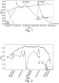
- Figure 1 depicts an exemplary embodiment of a normalized difference vegetation index, NDVI, over time, in form of different dates, from remote sensor data DR, in particular satellite measurements, and local sensor data DL and highlights the differences particularly for a first image 1, a second image 2, a third image 3, a fourth image 4 and a fifth image 5 strongly diverging from local sensor data, which is a sign of atmospheric distortions such as clouds.
- NDVI normalized difference vegetation index
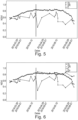
- Figure 2 depicts an exemplary embodiment of another NDVI over time from remote sensor data DR and local sensor data DL.
- the remote sensor data DR in particular deviate from the local sensor data DL in a first data point S1, a second data point S2, a third data point S3, a fourth data point D4 and a fifth data point S5.
- This again is a sign of atmospheric distortion such as clouds.
- Figure 3 depicts an exemplary embodiment of the remote sensor data DR and the local sensor data DL of figure 2 .
- the remote sensor data DR have a lower NDVI as the local sensor data DL, as the remote sensor data DR usually are determined by a satellite and distortions like atmospheric distortions have a higher impact on the remote sensor data DR than on the local sensor data DL. Consequently, the remote sensor data DR introduce a systemic underestimation of the real condition. This systemic underestimation difference in NDVI is overcome by correcting the remote sensor data, in this case current remote sensor data, to corrected current remote sensor data DRC based on the local sensor data DL and the remote sensor data DR.
- a correction model or prediction model determines the corrected remote sensor data DRC.
- the systemic underestimation difference of the local sensor data DL and the remote sensor data DR is determined and added to the remote sensor data DR to determine the corrected remote sensor data DRC.
- the values of the remote sensor data DR are increased by the determined systemic underestimation difference in NDVI.
- the local sensor data DL have an NDVI that is 0.1 higher than the remote sensor data DR. Consequently, each data point of the remote sensor data DR is increased by 0.1 to arrive at the corrected remote sensor data DRC.
- the remote sensor data DR are shifted up by 0.1.
- the systemic underestimation difference can alternatively be a predetermined value, for example from former test cycles.
- the corrected remote sensor data DRC indicate a corrected version of the remote sensor data DR.
- Figure 4 depicts an exemplary embodiment of the remote sensor data DR and the local sensor data DL of figure 3 .
- the correction model is configured for detecting outliers in the remote sensor data DR.
- a first data point S1, a second data point S2, a third data point S3, a fourth data point D4 and a fifth data point S5 deviate heavily from the corresponding local sensor data DL.
- the correction model compares the measurement values or in other words the NDVI values, of the remote sensor data DR and the local sensor data DL in each point in time and determines outliers if the difference of the remote sensor data DR and the local sensor data DL exceed a threshold. This threshold can be predetermined.
- the threshold can be dynamically adjusted by the correction model. Consequently, the determined outliers are not considered anymore, as they most likely correspond to unreasonable images.
- the correction model determines corrected remote sensor data with corrections DRCC, wherein the outliers of the remote sensor data DR are replaced by the correction model by corrected data points based on the corrected remote sensor data DRC and the local sensor data DL.
- the correction model takes the NDVI of the last non-rejected image from the satellite to determine the corrected remote sensor data with corrections DRCC.
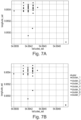
- Figures 5 and 6 depict an exemplary embodiment of further local sensor data DL and remote sensor data DR over time.
- the correction model predicts predicted sensor data DP based on the local sensor data DL after the cut off as well as the local sensor data DL and the remote sensor data DR before the cut off. Consequently, the correction model can fill out gaps for remote sensor data that are missing.
- Figure 7A shows an exemplary embodiment of location data from non-stationary local sensor.
- the measurement error in the locations of the sensor device are highlighted via the reported observations of the locations of the device that vary.
- the unique location of the sensor devices has to be found via e.g. single-linkage hierarchical clustering algorithm.
- clusters points are merged with minimal distance and a stop is introduced at a specified maximal distance.
- Figure 7B shows the clustered location data from non-stationary local sensor.
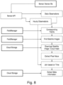
- Figure 8 shows an exemplary embodiment of a flow chart for sensor fusion.
- To find corresponding satellite data for the local sensor data hourly daily data for all available times / dates are extracted, in particular via a sensor application programming interface, sensor API. Based on daily data corresponding sensor device IDs from remote sensor data, in particular satellite data, for each observation are identified. Given the sensor device IDs corresponding data is retrieved from a field manager to find satellite data, or in other words satellite images, matching the date of the observation.
- the field manager comprises a field related database, in which the local sensor data is stored, as well as a decision support system for finding the relevant satellite data.
- the local data is stored in a cloud storage.
- a download of the surrounding pixels of the image for the location of the local sensor device is conducted.
- the download is conducted from a cloud storage, in which the satellite data is stored.
- the cropped satellite images for visual analysis may be stored and correct pixel values in relation to the local sensor data are identified. Based on the time of the satellite image and the local observations are joined. Lastly meta information of the satellite image (i.e. angle of the satellite) may be extracted.
- the methods disclosed herein provide field zone management solution combining in-field local sensor data from e.g. non-stationary local sensor, with satellite-based biomass and crop health indices.
- Using local sensor data leads to more accurate zone spray and allows for increased biomass, crop health maps and variable rate prescription map availability.
- Crop optimization platforms may include all the way from data collection and generation, through agronomic modelling, deriving insights to recommending action. With such platforms a grower knows when, where and how much to apply (e.g. fungicides). Certain further functionalities may include on in field variability in application or spray maps, and further instructions on e.g. the tank mix and the optimal treatment window for variable rate application. This may be particularly useful for fungicides. Monitoring functionalities may enable growers to inspect and compare plant growth and health across time and fields - daily and from every on the planet using our web and mobile solutions.
- Local sensors may by smart in the sense of having multiple sensor elements, highly-moveable, easy-to-install loT devices with sensor elements such as spectrometers or acoustic distrometers that is solar powered. Due to their design and manufacturing they may be virtually maintenance free.
- crop optimization platform By combining crop optimization platform with an in-field local sensor (e.g. non-stationary) the full automation and scalability potential of such platform yet backing up precise biomass, crop health analytic maps and variable rate application maps with the ground truth data may be exploited.
- an in-field local sensor e.g. non-stationary
- Trials support that this reduces biases e.g. in satellite-derived biomass and crop health indices. Additionally, through smartly combing satellite with local sensor data issues in satellite image availability can be overcome.
- seamless 1-click solution may be included in the platform. This provides convenience of having a one-stop-shop solution for inspecting how crops grow and taking actions based on the platform supported by in-field data from the local sensor.
Landscapes
- Engineering & Computer Science (AREA)
- Physics & Mathematics (AREA)
- Life Sciences & Earth Sciences (AREA)
- General Physics & Mathematics (AREA)
- Theoretical Computer Science (AREA)
- Health & Medical Sciences (AREA)
- General Health & Medical Sciences (AREA)
- Data Mining & Analysis (AREA)
- Chemical & Material Sciences (AREA)
- General Engineering & Computer Science (AREA)
- Artificial Intelligence (AREA)
- Evolutionary Computation (AREA)
- Analytical Chemistry (AREA)
- Pathology (AREA)
- Spectroscopy & Molecular Physics (AREA)
- Biochemistry (AREA)
- Immunology (AREA)
- Software Systems (AREA)
- Computing Systems (AREA)
- Computational Linguistics (AREA)
- Biomedical Technology (AREA)
- Mathematical Physics (AREA)
- Mechanical Engineering (AREA)
- Soil Sciences (AREA)
- Environmental Sciences (AREA)
- Molecular Biology (AREA)
- Biophysics (AREA)
- Botany (AREA)
- Wood Science & Technology (AREA)
- Food Science & Technology (AREA)
- Medicinal Chemistry (AREA)
- Evolutionary Biology (AREA)
- Computer Vision & Pattern Recognition (AREA)
- Bioinformatics & Computational Biology (AREA)
- Bioinformatics & Cheminformatics (AREA)
- Management, Administration, Business Operations System, And Electronic Commerce (AREA)
- Image Analysis (AREA)
- Image Processing (AREA)
- Arrangements For Transmission Of Measured Signals (AREA)
Claims (15)
- Verfahren zum Korrigieren von Fernsensordaten eines landwirtschaftlichen Feldes, wobei das Verfahren die folgenden Schritte umfasst:Empfangen von Fernsensordaten (DR) für das landwirtschaftliche Feld von einem Fernsensor, wobei die Fernsensordaten (DR) zumindest einen Fernmesswert umfassen, der zumindest einer Position entspricht, die von dem Fernsensor zu zumindest einem Zeitpunkt in der Vergangenheit des Erhaltens des Fernmesswertes gemessen wurde;Empfangen von lokalen Sensordaten (DL) für das landwirtschaftliche Feld von zumindest einem lokalen Sensor, wobei die lokalen Sensordaten (DL) zumindest einen lokalen Messwert umfassen, der zumindest einer Position des zumindest einen lokalen Sensors entspricht und zumindest einem Zeitpunkt des Erhaltens des lokalen Messwertes entspricht, der mit der Position und dem Zeitpunkt in der Vergangenheit des Erhaltens des Fernmesswertes korreliert;Bestimmen eines Korrekturmodells basierend auf den zuvor empfangenen lokalen Sensordaten (DL) und den zuvor empfangenen Fernsensordaten (DR); undBestimmen von korrigierten aktuellen Fernsensordaten (DRP, DRPR) durch Anwenden des Korrekturmodells auf aktuelle Fernsensordaten.
- Verfahren nach Anspruch 1, wobei der lokale Sensor nicht stationär ist.
- Verfahren nach einem der vorhergehenden Ansprüche, wobei
der Fernmesswert und/oder der lokale Messwert einem Hyperspektralindex oder einem Biomasseindex zugeordnet ist. - Verfahren nach einem der vorhergehenden Ansprüche, das die Schritte umfasst, nachdem die Fernsensordaten und die lokalen Sensordaten empfangen worden sind:Bestimmen des Fernmesswertes, der der Position des zumindest einen lokalen Sensors entspricht; undBestimmen einer Differenz zwischen dem Fernmesswert, der der Position des zumindest einen lokalen Sensors entspricht, und dem lokalen Messwert des zumindest einen lokalen Sensors für eine Mehrzahl von Zeitpunkten;wobei das Bestimmen des Korrekturmodells ferner auf der bestimmten Differenz basiert.
- Verfahren nach einem der vorhergehenden Ansprüche, wobeidie Fernsensordaten zumindest ein Fernbild umfassen, das auf dem zumindest einen Fernmesswert basiert, wobeidas Bestimmen des Fernmesswertes, der der Position des lokalen Sensors entspricht, den folgenden Schritt umfasst:Extrahieren eines Pixels aus dem Fernbild, das der Position des lokalen Sensors am nächsten ist, oder Extrahieren eines Mittels von Pixeln innerhalb eines vordefinierten Abstands zu dem Pixel, das der Position des lokalen Sensors am nächsten ist;Bestimmen des Fernmesswertes basierend auf dem extrahierten Pixel,wobei das Bestimmen des Korrekturmodells auch auf dem extrahierten Pixel basiert, auf dem der Fernmesswert basiert.
- Verfahren nach einem der Ansprüche 4 oder 5, wobei das Bestimmen einer Differenz zwischen dem Fernmesswert die folgenden Schritte umfasst:Empfangen lokaler Zeitreihendaten der lokalen Sensordaten (DL) von dem zumindest einen lokalen Sensor, wobei die lokalen Zeitreihendaten eine Mehrzahl von Positionsdaten einer Mehrzahl von Zeitpunkten umfassen, die der Position entsprechen, wo der zumindest eine lokale Sensor sich zu einem bestimmten Zeitpunkt befindet;Bestimmen eines Clusters lokaler Sensordaten basierend auf einem maximalen Abstand zwischen den jeweiligen Positionen der lokalen Sensoren über die Zeit;Bestimmen einer geclusterten Position des zumindest einen lokalen Sensors basierend auf dem bestimmten Cluster; undBestimmen der Differenz zwischen dem Fernmesswert, der der geclusterten Position des zumindest einen lokalen Sensors entspricht, und dem lokalen Messwert des zumindest einen lokalen Sensors für eine Mehrzahl von Zeitpunkten;wobei das Bestimmen des Korrekturmodells ferner auf der bestimmten Differenz basiert.
- Verfahren nach Anspruch 6, wobei
die geclusterte Position durch Bestimmen eines Zentrums des Clusters bestimmt wird. - Verfahren nach einem der vorhergehenden Ansprüche, wobei das Verfahren die folgenden Schritte umfasst:wenn die empfangenen Fernzeitreihendaten zumindest eine Lücke umfassen, in der Fernsensordaten (DR) zu einem erwarteten Zeitpunkt in der Zeitreihe der Fernzeitreihendaten (DR) fehlen; dannEmpfangen von lokalen Sensordaten (DL) für den Zeitpunkt der Lücke; undBestimmen von vorausgesagten Fernsensordaten (DP) für den Zeitpunkt der Lücke basierend auf den empfangenen lokalen Sensordaten (DL).
- Verfahren nach Anspruch 8, wobei das Bestimmen der vorhergesagten Fernsensordaten (DP) umfasst:Empfangen von Fernsensordaten (DR) eines Zeitpunkts unmittelbar vor der Lücke; undBestimmen der vorhergesagten Fernsensordaten (DP) basierend auf den empfangenen Fernsensordaten (DR) des Zeitpunkts unmittelbar vor der Lücke.
- Verfahren nach einem der vorhergehenden Ansprüche, wobei das Korrekturmodell eine Projektionsfunktion umfasst, die auf historischen Datensätzen von Fernsensordaten und lokalen Sensordaten basiert, wobei die vorhergesagten Fernsensordaten basierend auf der Projektionsfunktion bestimmt werden.
- Verarbeitungsvorrichtung, die ausgelegt ist zum Empfangen von Fernsensordaten (DR) für das landwirtschaftliche Feld von einem Fernsensor, wobei die Fernsensordaten (DR) zumindest einen Fernmesswert umfassen, der zumindest einer Position entspricht, die von dem Fernsensor zu zumindest einem Zeitpunkt in der Vergangenheit des Erhaltens des Fernmesswertes gemessen wurde;Empfangen von lokalen Sensordaten (DL) für das landwirtschaftliche Feld von zumindest einem lokalen Sensor, wobei die lokalen Sensordaten (DL) zumindest einen lokalen Messwert umfassen, der zumindest einer Position des zumindest einen lokalen Sensors entspricht und zumindest einem Zeitpunkt des Erhaltens des lokalen Messwertes entspricht, der mit der Position und dem Zeitpunkt in der Vergangenheit des Erhaltens des Fernmesswertes korreliert;Bestimmen eines Korrekturmodells basierend auf den zuvor empfangenen lokalen Sensordaten (DL) und den zuvor empfangenen Fernsensordaten (DR); undBestimmen von korrigierten aktuellen Fernsensordaten (DRP, DRPR) durch Anwenden des Korrekturmodells auf aktuelle Fernsensordaten.
- System zum Korrigieren von Fernsensordaten eines landwirtschaftlichen Feldes, das umfassteinen Fernsensor, der dazu ausgelegt ist Fernsensordaten (DR) für das landwirtschaftliche Feld von einem Fernsensor bereitzustellen, wobei die Fernsensordaten (DR) zumindest einen Fernmesswert umfassen, der zumindest einer Position entspricht, die von dem Fernsensor zu zumindest einem Zeitpunkt in der Vergangenheit des Erhaltens des Fernmesswertes gemessen wurde;einen lokalen Sensor, der dazu ausgelegt ist lokale Sensordaten (DL) für das landwirtschaftliche Feld von zumindest einem lokalen Sensor bereitzustellen, wobei die lokalen Sensordaten (DL) zumindest einen lokalen Messwert umfassen, der zumindest einer Position des zumindest einen lokalen Sensors entspricht und zumindest einem Zeitpunkt des Erhaltens des lokalen Messwertes entspricht, der mit der Position und dem Zeitpunkt in der Vergangenheit des Erhaltens des Fernmesswertes korreliert; undeine Verarbeitungsvorrichtung nach Anspruch 11.
- Computerprogramm, das computerlesbare Anweisungen umfasst, die, wenn sie bei einer Verarbeitungsvorrichtung geladen und ausgeführt werden, die Verfahren nach einem der Ansprüche 1 bis 10 durchführen.
- Computerlesbares nichtflüchtiges Speichermedium, das zum Speichern eines Computerprogramms nach Anspruch 13 ausgelegt ist.
- Verwenden von Fernsensordaten für das landwirtschaftliche Feld und von lokalen Sensordaten für das landwirtschaftliche Feld in einem Verfahren nach einem der Ansprüche 1 bis 10.
Applications Claiming Priority (3)
| Application Number | Priority Date | Filing Date | Title |
|---|---|---|---|
| EP19183266 | 2019-06-28 | ||
| EP19183430 | 2019-06-28 | ||
| PCT/EP2020/068088 WO2020260626A1 (en) | 2019-06-28 | 2020-06-26 | Sensor fusion |
Publications (2)
| Publication Number | Publication Date |
|---|---|
| EP3989698A1 EP3989698A1 (de) | 2022-05-04 |
| EP3989698B1 true EP3989698B1 (de) | 2024-12-11 |
Family
ID=71401755
Family Applications (1)
| Application Number | Title | Priority Date | Filing Date |
|---|---|---|---|
| EP20735335.0A Active EP3989698B1 (de) | 2019-06-28 | 2020-06-26 | Sensorfusion |
Country Status (8)
| Country | Link |
|---|---|
| US (1) | US20220253991A1 (de) |
| EP (1) | EP3989698B1 (de) |
| JP (1) | JP7707085B2 (de) |
| CN (1) | CN114026609A (de) |
| BR (1) | BR112021025393A2 (de) |
| CA (1) | CA3144030A1 (de) |
| ES (1) | ES3014252T3 (de) |
| WO (1) | WO2020260626A1 (de) |
Families Citing this family (2)
| Publication number | Priority date | Publication date | Assignee | Title |
|---|---|---|---|---|
| US20240169721A1 (en) * | 2021-03-31 | 2024-05-23 | Basf Agro Trademarks Gmbh | Computer-implemented method for providing corrected plant-related index data |
| WO2024096750A1 (en) * | 2022-11-01 | 2024-05-10 | Carbonco Limited | Methods and system for vegetation data acquisition and application |
Citations (10)
| Publication number | Priority date | Publication date | Assignee | Title |
|---|---|---|---|---|
| US20080063270A1 (en) | 2004-06-25 | 2008-03-13 | Digitalglobe, Inc. | Method and Apparatus for Determining a Location Associated With an Image |
| US20080234935A1 (en) | 2007-03-23 | 2008-09-25 | Qualcomm Incorporated | MULTI-SENSOR DATA COLLECTION and/or PROCESSING |
| US20090150000A1 (en) | 2007-12-07 | 2009-06-11 | Mark Stelford | System and method of managing substances in a plant root zone |
| US20120101634A1 (en) | 2010-10-25 | 2012-04-26 | Lindores Robert J | Crop treatment compatibility |
| US20130191017A1 (en) | 2009-11-16 | 2013-07-25 | Trimble Navigation Limited | Method and system for augmenting a guidance system with a path sensor |
| WO2016076289A1 (ja) | 2014-11-13 | 2016-05-19 | ヤンマー株式会社 | 農用作業車 |
| US20180070527A1 (en) | 2016-09-09 | 2018-03-15 | Cibo Technologies, Inc. | Systems for learning farmable zones, and related methods and apparatus |
| EP3299996A1 (de) | 2016-09-27 | 2018-03-28 | CLAAS Selbstfahrende Erntemaschinen GmbH | Landwirtschaftliche arbeitsmaschinen mit bildverarbeitungssystem |
| US20190050948A1 (en) | 2017-08-08 | 2019-02-14 | Indigo Ag, Inc. | Machine learning in agricultural planting, growing, and harvesting contexts |
| WO2019121097A1 (en) | 2017-12-21 | 2019-06-27 | Basf Se | Apparatus for determining agricultural relevant information |
Family Cites Families (6)
| Publication number | Priority date | Publication date | Assignee | Title |
|---|---|---|---|---|
| US8060269B2 (en) * | 2008-04-16 | 2011-11-15 | Cnh America Llc | Swath line creation including slope compensation for an automatic guidance system of a work vehicle |
| US10922383B2 (en) * | 2012-04-13 | 2021-02-16 | Adidas Ag | Athletic activity monitoring methods and systems |
| US9396528B2 (en) * | 2013-03-15 | 2016-07-19 | Digitalglobe, Inc. | Atmospheric compensation in satellite imagery |
| US9489576B2 (en) * | 2014-03-26 | 2016-11-08 | F12 Solutions, LLC. | Crop stand analysis |
| US9131644B2 (en) * | 2014-08-19 | 2015-09-15 | Iteris, Inc. | Continual crop development profiling using dynamical extended range weather forecasting with routine remotely-sensed validation imagery |
| JP6594529B2 (ja) * | 2016-04-27 | 2019-10-23 | 株式会社日立製作所 | 情報処理装置及び方法 |
-
2020
- 2020-06-26 EP EP20735335.0A patent/EP3989698B1/de active Active
- 2020-06-26 BR BR112021025393A patent/BR112021025393A2/pt unknown
- 2020-06-26 WO PCT/EP2020/068088 patent/WO2020260626A1/en not_active Ceased
- 2020-06-26 CA CA3144030A patent/CA3144030A1/en active Pending
- 2020-06-26 CN CN202080047198.2A patent/CN114026609A/zh active Pending
- 2020-06-26 US US17/621,885 patent/US20220253991A1/en active Pending
- 2020-06-26 JP JP2021577249A patent/JP7707085B2/ja active Active
- 2020-06-26 ES ES20735335T patent/ES3014252T3/es active Active
Patent Citations (11)
| Publication number | Priority date | Publication date | Assignee | Title |
|---|---|---|---|---|
| US20080063270A1 (en) | 2004-06-25 | 2008-03-13 | Digitalglobe, Inc. | Method and Apparatus for Determining a Location Associated With an Image |
| US20080234935A1 (en) | 2007-03-23 | 2008-09-25 | Qualcomm Incorporated | MULTI-SENSOR DATA COLLECTION and/or PROCESSING |
| US20090150000A1 (en) | 2007-12-07 | 2009-06-11 | Mark Stelford | System and method of managing substances in a plant root zone |
| US20130191017A1 (en) | 2009-11-16 | 2013-07-25 | Trimble Navigation Limited | Method and system for augmenting a guidance system with a path sensor |
| US20120101634A1 (en) | 2010-10-25 | 2012-04-26 | Lindores Robert J | Crop treatment compatibility |
| WO2016076289A1 (ja) | 2014-11-13 | 2016-05-19 | ヤンマー株式会社 | 農用作業車 |
| EP3219184A1 (de) | 2014-11-13 | 2017-09-20 | Yanmar Co., Ltd. | Landwirtschaftliches arbeitsfahrzeug |
| US20180070527A1 (en) | 2016-09-09 | 2018-03-15 | Cibo Technologies, Inc. | Systems for learning farmable zones, and related methods and apparatus |
| EP3299996A1 (de) | 2016-09-27 | 2018-03-28 | CLAAS Selbstfahrende Erntemaschinen GmbH | Landwirtschaftliche arbeitsmaschinen mit bildverarbeitungssystem |
| US20190050948A1 (en) | 2017-08-08 | 2019-02-14 | Indigo Ag, Inc. | Machine learning in agricultural planting, growing, and harvesting contexts |
| WO2019121097A1 (en) | 2017-12-21 | 2019-06-27 | Basf Se | Apparatus for determining agricultural relevant information |
Non-Patent Citations (2)
| Title |
|---|
| HUANG YANBO, CHEN ZHONG-XIN, YU TAO, HUANG XIANG-ZHI, GU XING-FA: "Agricultural remote sensing big data: Management and applications", JOURNAL OF INTEGRATIVE AGRICULTURE, ELSEVIER, AMSTERDAM, NL, vol. 17, no. 9, 1 September 2018 (2018-09-01), AMSTERDAM, NL, pages 1915 - 1931, XP093316402, ISSN: 2095-3119, DOI: 10.1016/S2095-3119(17)61859-8 |
| PREY LUKAS; SCHMIDHALTER URS: "Simulation of satellite reflectance data using high-frequency ground based hyperspectral canopy measurements for in-season estimation of grain yield and grain nitrogen status in winter wheat", ISPRS JOURNAL OF PHOTOGRAMMETRY AND REMOTE SENSING, AMSTERDAM [U.A.] : ELSEVIER, AMSTERDAM, NL, vol. 149, 1 January 1900 (1900-01-01), AMSTERDAM, NL , pages 176 - 187, XP085616016, ISSN: 0924-2716, DOI: 10.1016/j.isprsjprs.2019.01.023 |
Also Published As
| Publication number | Publication date |
|---|---|
| JP7707085B2 (ja) | 2025-07-14 |
| ES3014252T3 (en) | 2025-04-21 |
| EP3989698A1 (de) | 2022-05-04 |
| WO2020260626A1 (en) | 2020-12-30 |
| US20220253991A1 (en) | 2022-08-11 |
| JP2022538597A (ja) | 2022-09-05 |
| CN114026609A (zh) | 2022-02-08 |
| CA3144030A1 (en) | 2020-12-30 |
| BR112021025393A2 (pt) | 2022-02-01 |
Similar Documents
| Publication | Publication Date | Title |
|---|---|---|
| US12444189B2 (en) | Methods and systems for classifying and benchmarking irrigation performance | |
| US11672212B2 (en) | Customized land surface modeling for irrigation decision support for targeted transport of nitrogen and other nutrients to a crop root zone in a soil system | |
| US20250245532A1 (en) | Using Optical Remote Sensors And Machine Learning Models To Predict Agronomic Field Property Data | |
| US20210209705A1 (en) | System and Method for Managing and Operating an Agricultural-Origin-Product Manufacturing Supply Chain | |
| US10241098B2 (en) | Continual crop development profiling using dynamical extended range weather forecasting with routine remotely-sensed validation imagery | |
| EP4245126B1 (de) | Verfahren zur kartierung von zeitlicher und räumlicher nachhaltigkeit eines anbausystems | |
| US20150254800A1 (en) | Nitrogen status determination in growing crops | |
| An-Vo et al. | Value of seasonal forecasting for sugarcane farm irrigation planning | |
| US20220309595A1 (en) | System and Method for Managing and Operating an Agricultural-Origin-Product Manufacturing Supply Chain | |
| WO2021053118A1 (en) | A decision support system and method for agriculture | |
| EP3989698B1 (de) | Sensorfusion | |
| Fita et al. | Improving harvester yield maps postprocessing leveraging remote sensing data in rice crop | |
| CN112036313A (zh) | 烟草种植面积检测方法、装置、设备及可读存储介质 | |
| Singla et al. | Spatiotemporal analysis of LANDSAT Data for Crop Yield Prediction. | |
| CN115526713A (zh) | 一种农户贷款的授信额度确定方法及装置 | |
| EP4395526B1 (de) | Verfahren und system zur bereitstellung einer ortsspezifischen düngemittelempfehlung | |
| Pagano et al. | Internet of things and artificial intelligence for sustainable agriculture: a use case in citrus orchards | |
| Warner et al. | Agricultural impacts of the 2015/2016 drought in Ethiopia using high-resolution data fusion methodologies | |
| Lagasio et al. | Integrating Advanced Sensor Technologies for Enhanced Agricultural Weather Forecasts and Irrigation Advisories: The MAGDA Project Approach | |
| Habyarimana et al. | Yield Prediction in Sorghum (Sorghum bicolor (L.) Moench) and Cultivated Potato (Solanum tuberosum L.) | |
| Juliet et al. | Intelligent Crop Yield Prediction Using IoT and Optimized Deep Learning for Precision Agriculture | |
| Kataev et al. | Determination of Plant Phenological Cycle from RGB Images |
Legal Events
| Date | Code | Title | Description |
|---|---|---|---|
| STAA | Information on the status of an ep patent application or granted ep patent |
Free format text: STATUS: UNKNOWN |
|
| STAA | Information on the status of an ep patent application or granted ep patent |
Free format text: STATUS: THE INTERNATIONAL PUBLICATION HAS BEEN MADE |
|
| PUAI | Public reference made under article 153(3) epc to a published international application that has entered the european phase |
Free format text: ORIGINAL CODE: 0009012 |
|
| STAA | Information on the status of an ep patent application or granted ep patent |
Free format text: STATUS: REQUEST FOR EXAMINATION WAS MADE |
|
| 17P | Request for examination filed |
Effective date: 20220128 |
|
| AK | Designated contracting states |
Kind code of ref document: A1 Designated state(s): AL AT BE BG CH CY CZ DE DK EE ES FI FR GB GR HR HU IE IS IT LI LT LU LV MC MK MT NL NO PL PT RO RS SE SI SK SM TR |
|
| DAV | Request for validation of the european patent (deleted) | ||
| DAX | Request for extension of the european patent (deleted) | ||
| GRAP | Despatch of communication of intention to grant a patent |
Free format text: ORIGINAL CODE: EPIDOSNIGR1 |
|
| STAA | Information on the status of an ep patent application or granted ep patent |
Free format text: STATUS: GRANT OF PATENT IS INTENDED |
|
| RIC1 | Information provided on ipc code assigned before grant |
Ipc: A01M 7/00 20060101ALN20240129BHEP Ipc: A01B 79/00 20060101ALI20240129BHEP Ipc: A01B 69/04 20060101AFI20240129BHEP |
|
| INTG | Intention to grant announced |
Effective date: 20240212 |
|
| GRAJ | Information related to disapproval of communication of intention to grant by the applicant or resumption of examination proceedings by the epo deleted |
Free format text: ORIGINAL CODE: EPIDOSDIGR1 |
|
| STAA | Information on the status of an ep patent application or granted ep patent |
Free format text: STATUS: REQUEST FOR EXAMINATION WAS MADE |
|
| GRAP | Despatch of communication of intention to grant a patent |
Free format text: ORIGINAL CODE: EPIDOSNIGR1 |
|
| STAA | Information on the status of an ep patent application or granted ep patent |
Free format text: STATUS: GRANT OF PATENT IS INTENDED |
|
| INTC | Intention to grant announced (deleted) | ||
| RIC1 | Information provided on ipc code assigned before grant |
Ipc: A01M 7/00 20060101ALN20240613BHEP Ipc: A01B 79/00 20060101ALI20240613BHEP Ipc: A01B 69/04 20060101AFI20240613BHEP |
|
| INTG | Intention to grant announced |
Effective date: 20240702 |
|
| GRAS | Grant fee paid |
Free format text: ORIGINAL CODE: EPIDOSNIGR3 |
|
| GRAA | (expected) grant |
Free format text: ORIGINAL CODE: 0009210 |
|
| STAA | Information on the status of an ep patent application or granted ep patent |
Free format text: STATUS: THE PATENT HAS BEEN GRANTED |
|
| AK | Designated contracting states |
Kind code of ref document: B1 Designated state(s): AL AT BE BG CH CY CZ DE DK EE ES FI FR GB GR HR HU IE IS IT LI LT LU LV MC MK MT NL NO PL PT RO RS SE SI SK SM TR |
|
| REG | Reference to a national code |
Ref country code: GB Ref legal event code: FG4D |
|
| REG | Reference to a national code |
Ref country code: CH Ref legal event code: EP |
|
| REG | Reference to a national code |
Ref country code: IE Ref legal event code: FG4D |
|
| REG | Reference to a national code |
Ref country code: DE Ref legal event code: R096 Ref document number: 602020042946 Country of ref document: DE |
|
| REG | Reference to a national code |
Ref country code: LT Ref legal event code: MG9D |
|
| PG25 | Lapsed in a contracting state [announced via postgrant information from national office to epo] |
Ref country code: HR Free format text: LAPSE BECAUSE OF FAILURE TO SUBMIT A TRANSLATION OF THE DESCRIPTION OR TO PAY THE FEE WITHIN THE PRESCRIBED TIME-LIMIT Effective date: 20241211 |
|
| PG25 | Lapsed in a contracting state [announced via postgrant information from national office to epo] |
Ref country code: FI Free format text: LAPSE BECAUSE OF FAILURE TO SUBMIT A TRANSLATION OF THE DESCRIPTION OR TO PAY THE FEE WITHIN THE PRESCRIBED TIME-LIMIT Effective date: 20241211 |
|
| PG25 | Lapsed in a contracting state [announced via postgrant information from national office to epo] |
Ref country code: BG Free format text: LAPSE BECAUSE OF FAILURE TO SUBMIT A TRANSLATION OF THE DESCRIPTION OR TO PAY THE FEE WITHIN THE PRESCRIBED TIME-LIMIT Effective date: 20241211 |
|
| REG | Reference to a national code |
Ref country code: NL Ref legal event code: MP Effective date: 20241211 |
|
| REG | Reference to a national code |
Ref country code: ES Ref legal event code: FG2A Ref document number: 3014252 Country of ref document: ES Kind code of ref document: T3 Effective date: 20250421 |
|
| PG25 | Lapsed in a contracting state [announced via postgrant information from national office to epo] |
Ref country code: NO Free format text: LAPSE BECAUSE OF FAILURE TO SUBMIT A TRANSLATION OF THE DESCRIPTION OR TO PAY THE FEE WITHIN THE PRESCRIBED TIME-LIMIT Effective date: 20250311 |
|
| PG25 | Lapsed in a contracting state [announced via postgrant information from national office to epo] |
Ref country code: GR Free format text: LAPSE BECAUSE OF FAILURE TO SUBMIT A TRANSLATION OF THE DESCRIPTION OR TO PAY THE FEE WITHIN THE PRESCRIBED TIME-LIMIT Effective date: 20250312 Ref country code: LV Free format text: LAPSE BECAUSE OF FAILURE TO SUBMIT A TRANSLATION OF THE DESCRIPTION OR TO PAY THE FEE WITHIN THE PRESCRIBED TIME-LIMIT Effective date: 20241211 |
|
| PG25 | Lapsed in a contracting state [announced via postgrant information from national office to epo] |
Ref country code: RS Free format text: LAPSE BECAUSE OF FAILURE TO SUBMIT A TRANSLATION OF THE DESCRIPTION OR TO PAY THE FEE WITHIN THE PRESCRIBED TIME-LIMIT Effective date: 20250311 |
|
| PG25 | Lapsed in a contracting state [announced via postgrant information from national office to epo] |
Ref country code: NL Free format text: LAPSE BECAUSE OF FAILURE TO SUBMIT A TRANSLATION OF THE DESCRIPTION OR TO PAY THE FEE WITHIN THE PRESCRIBED TIME-LIMIT Effective date: 20241211 |
|
| REG | Reference to a national code |
Ref country code: AT Ref legal event code: MK05 Ref document number: 1749550 Country of ref document: AT Kind code of ref document: T Effective date: 20241211 |
|
| PG25 | Lapsed in a contracting state [announced via postgrant information from national office to epo] |
Ref country code: SM Free format text: LAPSE BECAUSE OF FAILURE TO SUBMIT A TRANSLATION OF THE DESCRIPTION OR TO PAY THE FEE WITHIN THE PRESCRIBED TIME-LIMIT Effective date: 20241211 |
|
| PG25 | Lapsed in a contracting state [announced via postgrant information from national office to epo] |
Ref country code: PL Free format text: LAPSE BECAUSE OF FAILURE TO SUBMIT A TRANSLATION OF THE DESCRIPTION OR TO PAY THE FEE WITHIN THE PRESCRIBED TIME-LIMIT Effective date: 20241211 |
|
| PGFP | Annual fee paid to national office [announced via postgrant information from national office to epo] |
Ref country code: DE Payment date: 20250626 Year of fee payment: 6 |
|
| PGFP | Annual fee paid to national office [announced via postgrant information from national office to epo] |
Ref country code: GB Payment date: 20250617 Year of fee payment: 6 |
|
| PG25 | Lapsed in a contracting state [announced via postgrant information from national office to epo] |
Ref country code: IS Free format text: LAPSE BECAUSE OF FAILURE TO SUBMIT A TRANSLATION OF THE DESCRIPTION OR TO PAY THE FEE WITHIN THE PRESCRIBED TIME-LIMIT Effective date: 20250411 |
|
| PG25 | Lapsed in a contracting state [announced via postgrant information from national office to epo] |
Ref country code: PT Free format text: LAPSE BECAUSE OF FAILURE TO SUBMIT A TRANSLATION OF THE DESCRIPTION OR TO PAY THE FEE WITHIN THE PRESCRIBED TIME-LIMIT Effective date: 20250411 |
|
| PG25 | Lapsed in a contracting state [announced via postgrant information from national office to epo] |
Ref country code: EE Free format text: LAPSE BECAUSE OF FAILURE TO SUBMIT A TRANSLATION OF THE DESCRIPTION OR TO PAY THE FEE WITHIN THE PRESCRIBED TIME-LIMIT Effective date: 20241211 |
|
| PGFP | Annual fee paid to national office [announced via postgrant information from national office to epo] |
Ref country code: FR Payment date: 20250624 Year of fee payment: 6 |
|
| PG25 | Lapsed in a contracting state [announced via postgrant information from national office to epo] |
Ref country code: AT Free format text: LAPSE BECAUSE OF FAILURE TO SUBMIT A TRANSLATION OF THE DESCRIPTION OR TO PAY THE FEE WITHIN THE PRESCRIBED TIME-LIMIT Effective date: 20241211 Ref country code: RO Free format text: LAPSE BECAUSE OF FAILURE TO SUBMIT A TRANSLATION OF THE DESCRIPTION OR TO PAY THE FEE WITHIN THE PRESCRIBED TIME-LIMIT Effective date: 20241211 |
|
| PG25 | Lapsed in a contracting state [announced via postgrant information from national office to epo] |
Ref country code: SK Free format text: LAPSE BECAUSE OF FAILURE TO SUBMIT A TRANSLATION OF THE DESCRIPTION OR TO PAY THE FEE WITHIN THE PRESCRIBED TIME-LIMIT Effective date: 20241211 |
|
| PG25 | Lapsed in a contracting state [announced via postgrant information from national office to epo] |
Ref country code: CZ Free format text: LAPSE BECAUSE OF FAILURE TO SUBMIT A TRANSLATION OF THE DESCRIPTION OR TO PAY THE FEE WITHIN THE PRESCRIBED TIME-LIMIT Effective date: 20241211 |
|
| RAP4 | Party data changed (patent owner data changed or rights of a patent transferred) |
Owner name: BASF AGRICULTURAL SOLUTIONS DEUTSCHLAND GMBH |
|
| RAP2 | Party data changed (patent owner data changed or rights of a patent transferred) |
Owner name: BASF DIGITAL FARMING GMBH |
|
| PG25 | Lapsed in a contracting state [announced via postgrant information from national office to epo] |
Ref country code: SE Free format text: LAPSE BECAUSE OF FAILURE TO SUBMIT A TRANSLATION OF THE DESCRIPTION OR TO PAY THE FEE WITHIN THE PRESCRIBED TIME-LIMIT Effective date: 20241211 |
|
| REG | Reference to a national code |
Ref country code: DE Ref legal event code: R026 Ref document number: 602020042946 Country of ref document: DE |
|
| PLBI | Opposition filed |
Free format text: ORIGINAL CODE: 0009260 |
|
| PLAB | Opposition data, opponent's data or that of the opponent's representative modified |
Free format text: ORIGINAL CODE: 0009299OPPO |
|
| PLAX | Notice of opposition and request to file observation + time limit sent |
Free format text: ORIGINAL CODE: EPIDOSNOBS2 |
|
| PGFP | Annual fee paid to national office [announced via postgrant information from national office to epo] |
Ref country code: ES Payment date: 20250710 Year of fee payment: 6 |
|
| PG25 | Lapsed in a contracting state [announced via postgrant information from national office to epo] |
Ref country code: DK Free format text: LAPSE BECAUSE OF FAILURE TO SUBMIT A TRANSLATION OF THE DESCRIPTION OR TO PAY THE FEE WITHIN THE PRESCRIBED TIME-LIMIT Effective date: 20241211 |
|
| 26 | Opposition filed |
Opponent name: YARA INTERNATIONAL ASA Effective date: 20250911 |
|
| PGFP | Annual fee paid to national office [announced via postgrant information from national office to epo] |
Ref country code: IT Payment date: 20250623 Year of fee payment: 6 |
|
| R26 | Opposition filed (corrected) |
Opponent name: YARA INTERNATIONAL ASA Effective date: 20250911 |