EP3989602B1 - Verzerrungskompensation für ein knochenverankertes hörgerät - Google Patents
Verzerrungskompensation für ein knochenverankertes hörgerät Download PDFInfo
- Publication number
- EP3989602B1 EP3989602B1 EP21201181.1A EP21201181A EP3989602B1 EP 3989602 B1 EP3989602 B1 EP 3989602B1 EP 21201181 A EP21201181 A EP 21201181A EP 3989602 B1 EP3989602 B1 EP 3989602B1
- Authority
- EP
- European Patent Office
- Prior art keywords
- electromagnetic vibrator
- signal
- hearing device
- distortion
- bone
- Prior art date
- Legal status (The legal status is an assumption and is not a legal conclusion. Google has not performed a legal analysis and makes no representation as to the accuracy of the status listed.)
- Active
Links
Images




Classifications
-
- H—ELECTRICITY
- H04—ELECTRIC COMMUNICATION TECHNIQUE
- H04R—LOUDSPEAKERS, MICROPHONES, GRAMOPHONE PICK-UPS OR LIKE ACOUSTIC ELECTROMECHANICAL TRANSDUCERS; ELECTRIC HEARING AIDS; PUBLIC ADDRESS SYSTEMS
- H04R25/00—Electric hearing aids
- H04R25/50—Customised settings for obtaining desired overall acoustical characteristics
-
- H—ELECTRICITY
- H04—ELECTRIC COMMUNICATION TECHNIQUE
- H04R—LOUDSPEAKERS, MICROPHONES, GRAMOPHONE PICK-UPS OR LIKE ACOUSTIC ELECTROMECHANICAL TRANSDUCERS; ELECTRIC HEARING AIDS; PUBLIC ADDRESS SYSTEMS
- H04R3/00—Circuits for transducers
- H04R3/04—Circuits for transducers for correcting frequency response
- H04R3/08—Circuits for transducers for correcting frequency response of electromagnetic transducers
-
- H—ELECTRICITY
- H04—ELECTRIC COMMUNICATION TECHNIQUE
- H04R—LOUDSPEAKERS, MICROPHONES, GRAMOPHONE PICK-UPS OR LIKE ACOUSTIC ELECTROMECHANICAL TRANSDUCERS; ELECTRIC HEARING AIDS; PUBLIC ADDRESS SYSTEMS
- H04R25/00—Electric hearing aids
- H04R25/45—Prevention of acoustic reaction, i.e. acoustic oscillatory feedback
- H04R25/453—Prevention of acoustic reaction, i.e. acoustic oscillatory feedback electronically
-
- H—ELECTRICITY
- H04—ELECTRIC COMMUNICATION TECHNIQUE
- H04R—LOUDSPEAKERS, MICROPHONES, GRAMOPHONE PICK-UPS OR LIKE ACOUSTIC ELECTROMECHANICAL TRANSDUCERS; ELECTRIC HEARING AIDS; PUBLIC ADDRESS SYSTEMS
- H04R3/00—Circuits for transducers
- H04R3/002—Damping circuit arrangements for transducers, e.g. motional feedback circuits
-
- H—ELECTRICITY
- H04—ELECTRIC COMMUNICATION TECHNIQUE
- H04R—LOUDSPEAKERS, MICROPHONES, GRAMOPHONE PICK-UPS OR LIKE ACOUSTIC ELECTROMECHANICAL TRANSDUCERS; ELECTRIC HEARING AIDS; PUBLIC ADDRESS SYSTEMS
- H04R2225/00—Details of deaf aids covered by H04R25/00, not provided for in any of its subgroups
- H04R2225/41—Detection or adaptation of hearing aid parameters or programs to listening situation, e.g. pub, forest
-
- H—ELECTRICITY
- H04—ELECTRIC COMMUNICATION TECHNIQUE
- H04R—LOUDSPEAKERS, MICROPHONES, GRAMOPHONE PICK-UPS OR LIKE ACOUSTIC ELECTROMECHANICAL TRANSDUCERS; ELECTRIC HEARING AIDS; PUBLIC ADDRESS SYSTEMS
- H04R2225/00—Details of deaf aids covered by H04R25/00, not provided for in any of its subgroups
- H04R2225/67—Implantable hearing aids or parts thereof not covered by H04R25/606
-
- H—ELECTRICITY
- H04—ELECTRIC COMMUNICATION TECHNIQUE
- H04R—LOUDSPEAKERS, MICROPHONES, GRAMOPHONE PICK-UPS OR LIKE ACOUSTIC ELECTROMECHANICAL TRANSDUCERS; ELECTRIC HEARING AIDS; PUBLIC ADDRESS SYSTEMS
- H04R2460/00—Details of hearing devices, i.e. of ear- or headphones covered by H04R1/10 or H04R5/033 but not provided for in any of their subgroups, or of hearing aids covered by H04R25/00 but not provided for in any of its subgroups
- H04R2460/13—Hearing devices using bone conduction transducers
-
- H—ELECTRICITY
- H04—ELECTRIC COMMUNICATION TECHNIQUE
- H04R—LOUDSPEAKERS, MICROPHONES, GRAMOPHONE PICK-UPS OR LIKE ACOUSTIC ELECTROMECHANICAL TRANSDUCERS; ELECTRIC HEARING AIDS; PUBLIC ADDRESS SYSTEMS
- H04R25/00—Electric hearing aids
- H04R25/60—Mounting or interconnection of hearing aid parts, e.g. inside tips, housings or to ossicles
- H04R25/604—Mounting or interconnection of hearing aid parts, e.g. inside tips, housings or to ossicles of acoustic or vibrational transducers
- H04R25/606—Mounting or interconnection of hearing aid parts, e.g. inside tips, housings or to ossicles of acoustic or vibrational transducers acting directly on the eardrum, the ossicles or the skull, e.g. mastoid, tooth, maxillary or mandibular bone, or mechanically stimulating the cochlea, e.g. at the oval window
Definitions
- the present disclosure relates to a bone anchored hearing device and to a signal processing method for a bone anchored hearing device.
- Bone anchored hearing devices typically use a vibrator/transducer technology to vibrate sound into the skull of a patient based on variable reluctance.
- the vibrator includes an anchor and a vibrator mean including a magnet and a coil.
- an implant such as a titanium screw
- an abutment is applied onto the screw.
- the vibrator is arranged onto the abutment via the anchor.
- the vibrator mean causes the anchor to vibrate by transferring a magnetic force to the anchor.
- the anchor moves along a longitudinal direction, applying a vibrational force to the abutment, which in turn transfers the vibration into the skull of the patient.
- the (output) transducer would have a symmetric movement with low distortion.
- the magnetic force between the anchor and the magnet depends on their distance (the magnetic force increases with decreasing distance and decreases with increasing distance).
- This variation of the magnetic force in dependence of the distance leads to an asymmetric behavior of the vibrator, i.e. the magnetic force is not the same throughout the movement of the vibrator.
- the movement does not have a linear relation to an input signal, effectively leading to unwanted distortions in the vibration.
- variable reluctance vibrators as well as other systems with an asymmetrical behavior.
- Document US 2013/208935 describes a network for bone conduction transducers.
- Document CN 105 721 973 describes a bone conduction headset and an audio processing method.
- a bone anchored hearing according to claim 1 is provided.
- a signal processing method for a bone anchored hearing device comprising: providing, by an input transducer, an electric input signal representing sound of a surrounding of a user of the bone anchored hearing device; processing, by a signal processing unit, the electric input signal and providing a processed electric signal; generating, by an electromagnetic vibrator, based on the processed electric signal, a vibration in order to transmit sound through a bone of the user to an ear of the user; and at least in part compensating, by a compensator, a distortion in the vibration of the electromagnetic vibrator, wherein the compensation of the distortion is based on a dependence of a driving force acting on a vibrating component of the electromagnetic vibrator on a displacement of the vibrating component.
- a computer program comprising instructions which, when the program is executed by a computer, cause the computer to carry out (steps of) the method of the second aspect
- Exemplary embodiments of the first and the second aspect may have one or more of the properties described below.
- the electromagnetic vibrator is a part of or is an output transducer configured for receiving an electric input signal and/or providing a mechanical output signal to the bone of the user.
- the electric input signal represents the sound from the surrounding of the user. In other words, physical properties of the sound are represented by the electric input signal.
- the mechanical output signal may correspond to an acoustic signal such as mechanical vibrations reaching the user's inner ear (the vibration).
- the sound transmitted by the electromagnetic vibrator is a sound from a surrounding of the user.
- the electromagnetic vibrator advantageously allows for improving or augmenting the hearing capability of the user.
- At least in part compensating a distortion in the vibration with the compensator is in particular understood as (at least in part) reducing, preventing, and/or avoiding a respective distortion in the vibration, which would otherwise occur in the vibration in the absence of the compensator.
- a compensator may generally be realized by software and/or hardware.
- the compensator may be a software or hardware module.
- the compensator may be implemented in one or more otherwise already present modules of the hearing device, such as a signal processing unit.
- the compensator may be employed to work with signals in the digital domain and/or in analog domain.
- the suggested approach allows to provide an output signal (and thus a signal perceived by the user), which is free of or only has minimal unwanted distortions, even though an electromagnetic vibrator is used, which usually is intrinsically susceptible for such distortions due to the physical working principles of electromagnetic vibrators, which will also be explained in further detail below.
- electromagnetic vibrators it is possible to employ such electromagnetic vibrators without the disadvantage of unwanted distortions, which would otherwise not be possible.
- the compensation can be realized in the electrical domain without the need for complex (and thus error susceptible) mechanical solutions.
- a hearing device may be or include a hearing aid that is adapted to improve or augment the hearing capability of a user by receiving an acoustic signal from a user's surroundings, generating a corresponding audio signal, possibly modifying the audio signal and providing the possibly modified audio signal as an audible signal to at least one of the user's ears.
- Such audible signals may be provided in the form of an acoustic signal transferred as mechanical vibrations to the user's inner ears through bone structure of the user's head and/or through parts of middle ear of the user.
- ⁇ Improving or augmenting the hearing capability of a user' may include compensating for an individual user's specific hearing loss.
- the hearing device may further refer to a device such as a hearable, an earphone or a headset adapted to receive an audio signal electronically, possibly modifying the audio signal and providing the possibly modified audio signals as an audible signal to at least one of the user's ears.
- a device such as a hearable, an earphone or a headset adapted to receive an audio signal electronically, possibly modifying the audio signal and providing the possibly modified audio signals as an audible signal to at least one of the user's ears.
- the hearing device is adapted to be worn in any known way. This may include arranging a unit of the hearing device attached to a fixture implanted into the skull bone such as in bone anchored hearing aids, or arranging a unit of the hearing device as an entirely or partly implanted unit such as in bone anchored hearing aids.
- the hearing device may include i) an input unit such as a microphone for receiving an acoustic signal from a user's surroundings and providing a corresponding input audio signal, and/or ii) a receiving unit for electronically receiving an input audio signal.
- the hearing device further includes a signal processing unit for processing the input audio signal and an output unit for providing an audible signal to the user in dependence on the processed audio signal.
- the input unit may include multiple input microphones, e.g. for providing direction-dependent audio signal processing.
- Such directional microphone system is adapted to (relatively) enhance a target acoustic source among a multitude of acoustic sources in the user's environment and/or to attenuate other sources (e.g. noise).
- the directional system is adapted to detect (such as adaptively detect) from which direction a particular part of the microphone signal originates. This may be achieved by using conventionally known methods.
- the signal processing unit may include an amplifier that is adapted to apply a frequency dependent gain to the input audio signal.
- the signal processing unit may further be adapted to provide other relevant functionality such as compression, noise reduction, etc.
- the output unit may include an output transducer such as a loudspeaker/receiver for providing an air-borne acoustic signal to the ear of the user, a mechanical stimulation applied transcutaneously or percutaneously to the skull bone or a vibrator for providing a structure-borne or liquid-borne acoustic signal.
- an output transducer such as a loudspeaker/receiver for providing an air-borne acoustic signal to the ear of the user, a mechanical stimulation applied transcutaneously or percutaneously to the skull bone or a vibrator for providing a structure-borne or liquid-borne acoustic signal.
- the described hearing device may be part of a hearing system.
- a hearing system refers to a system comprising one or two hearing devices
- a “binaural hearing system” or a bimodal hearing system refers to a system comprising two hearing devices where the devices are adapted to cooperatively provide audible signals to both of the user's ears either by acoustic stimulation only, acoustic and mechanical stimulation, mechanical stimulation only, acoustic and electrical stimulation, mechanical and electrical stimulation or only electrical stimulation.
- the hearing system, the binaural hearing system or the bimodal hearing system may further include one or more auxiliary device(s) that communicates with at least one hearing device, the auxiliary device affecting the operation of the hearing devices and/or benefitting from the functioning of the hearing devices.
- a wired or wireless communication link between the at least one hearing device and the auxiliary device is established that allows for exchanging information (e.g. control and status signals, possibly audio signals) between the at least one hearing device and the auxiliary device.
- auxiliary devices may include at least one of a remote control, a remote microphone, an audio gateway device, a wireless communication device, e.g. a mobile phone (such as a smartphone) or a tablet or another device, e.g. comprising a graphical interface, a public-address system, a car audio system or a music player, or a combination thereof.
- the audio gateway may be adapted to receive a multitude of audio signals such as from an entertainment device like a TV or a music player, a telephone apparatus like a mobile telephone or a computer, e.g. a PC.
- the auxiliary device may further be adapted to (e.g. allow a user to) select and/or combine an appropriate one of the received audio signals (or combination of signals) for transmission to the at least one hearing device.
- the remote control is adapted to control functionality and/or operation of the at least one hearing device.
- the function of the remote control may be implemented in a smartphone or other (e.g. portable) electronic device, the smartphone / electronic device possibly running an application (APP) that controls functionality of the at least one hearing device.
- APP application
- Electronic hardware may include micro-electronic-mechanical systems (MEMS), integrated circuits (e.g. application specific), microprocessors, microcontrollers, digital signal processors (DSPs), field programmable gate arrays (FPGAs), programmable logic devices (PLDs), gated logic, discrete hardware circuits, printed circuit boards (PCB) (e.g. flexible PCBs), and other suitable hardware configured to perform the various functionality described throughout this disclosure, e.g. sensors, e.g. for sensing and/or registering physical properties of the environment, the device, the user, etc.
- MEMS micro-electronic-mechanical systems
- DSPs digital signal processors
- FPGAs field programmable gate arrays
- PLDs programmable logic devices
- gated logic discrete hardware circuits
- PCB printed circuit boards
- PCB printed circuit boards
- Computer program shall be construed broadly to mean instructions, instruction sets, code, code segments, program code, programs, subprograms, software modules, applications, software applications, software packages, routines, subroutines, objects, executables, threads of execution, procedures, functions, etc., whether referred to as software, firmware, middleware, microcode, hardware description language, or otherwise.
- the distortion is one or more of a harmonic distortion in the vibration and/or a distortion due to an asymmetric behavior of the electromagnetic vibrator.
- the asymmetric behavior of the electromagnetic vibrator leads mainly to the harmonic distortion and less to the inharmonic distortion. Thereby, by reducing or eliminating the asymmetric behavior of the electromagnetic vibrator would result in a reduction or elimination of the harmonic and inharmonic distortion.
- harmonic distortion may be understood as the presence of overtones, wherein overtones are whole number multiples of frequencies comprised by the sound
- inharmonic distortion may be understood as a distortion resulting from general intermodulation distortion
- the asymmetric behavior of the electromagnetic vibrator may refer to a dependence of a magnetic force exerted by an electromagnetic component of the electromagnetic vibrator on a vibrating component of the electromagnetic vibrator on a position of the vibrating component with respect to a position of the electromagnetic component.
- the magnetic force depends on the distance between the electromagnetic component and the vibrating component.
- the magnetic force is inversely proportional to the distance squared.
- At least in part compensating harmonic distortions, inharmonic distortions and/or distortions due to the asymmetric behavior of the electromagnetic vibrator advantageously allows for providing an improved user experience when using the bone anchored hearing device.
- the compensator is configured for receiving an uncompensated signal and/or for providing a compensated signal to the electromagnetic vibrator for at least in part compensating the distortion in the vibration of the electromagnetic vibrator.
- the uncompensated signal is an (e.g. processed or unprocessed) electric input signal representing the sound from the surrounding of the user.
- the compensated signal may for instance be directly fed into the electromagnetic vibrator or may be processed further before being fed into the electromagnetic vibrator.
- the uncompensated signal to the electromagnetic vibrator when providing the uncompensated signal to the electromagnetic vibrator, at least some distortion in the vibration will occur. When providing, in an exemplary embodiment, however, the compensated signal to the electromagnetic vibrator, no or at least less distortion will occur.
- No or at least less distortion in the vibration is advantageous as it enables an improved user experience when using the bone anchored hearing device.
- the compensated signal provided to the electromagnetic vibrator comprises one or more of the uncompensated signal and/or a compensation signal.
- the compensated signal is a superposition of the uncompensated signal and the compensation signal.
- the compensated signal may be a convolution of the uncompensated signal and the compensation signal.
- the compensated signal is a modified electric input signal comprising the electric input signal and the compensation signal.
- the compensation signal may in particular be an electric signal.
- the compensation signal is measured and/or saved in a table and/or function, and/or is calculated from physical properties of the electromagnetic vibrator.
- the compensation signal comprises a behavior which is the opposite of the asymmetric behavior of the electromagnetic vibrator.
- the compensation signal may mirror the asymmetrical behavior of the electromagnetic vibrator such that the compensation signal cancels out the asymmetric behavior of the electromagnetic vibrator.
- cancelling out means that when the compensated signal is provided to the electromagnetic vibrator no or at least less distortion in the vibration will occur.
- the bone anchored hearing device is configured to apply a supply voltage to the vibrator based on the uncompensated signal, and by implementing the compensator into the hearing device, the hearing device is configured to apply a supply voltage to the vibrator based on the compensated signal.
- the uncompensated signal is an electric signal representing the sound from the surrounding of the user.
- the compensated signal is an electric input signal representing the sound from the surrounding of the user and a compensation of the distortion in the vibration of the electromagnetic vibrator.
- the hearing device may include a memory that comprises a measure of the distortion as a function of supply voltage applied to the electromagnetic vibrator.
- the measured distortion may include measured magnetic force between the magnet and the anchor as a function of supply voltage applied to the electromagnetic vibrator.
- the measurement may be performed during a fitting scenario of the bone anchored hearing device to the user.
- the compressor receives the uncompensated signal and extracts from the memory the measured distortion as a function of the supply voltage.
- the compressor determines a first supply voltage based on the uncompensated signal and then determines an expected distortion as a function of the first supply voltage by the measured distortion from the memory.
- the compressor is then configured to determine the supply voltage to the vibrator which is determined as being symmetrical or partially symmetrically in relation to the first supply voltage.
- the supply voltage is then transmitted to the electromagnetic vibrator which then cancels out or reduces the distortion of the electromagnetic vibrator which would have occurred if the first supply voltage was provided to the electromagnetic vibrator.
- the compensator is configured to determine the supply voltage without knowing the measured distortion.
- the compensator is configured to determine a supply voltage to the vibrator which is symmetrical or partially symmetrically to the first supply voltage which is determined by the compensator based on the uncompensated signal.
- the magnetic force exerted by the electromagnetic component on the vibrating component does not depend on the distance between the vibrating component and the electromagnetic component anymore.
- the compensator may be arranged on a printed circuit board which is arranged within the bone anchored hearing aid.
- the compensator receives the uncompensated signal via the receiver coil and the measured distortion from the memory. Thereby, the compensator is connected to the receiver coil and the memory.
- Using a compensation signal in order to obtain the compensated signal thus advantageously allows for at least in part compensating the distortion in the vibration leading to an enhanced user experience.
- the compensation signal is comprised by a supply voltage of the electromagnetic vibrator, in particular of a coil of the electromagnetic vibrator.
- the supply voltage mirrors the asymmetrical behavior of the electromagnetic vibrator.
- the supply voltage may depend on the distance between the vibrating component and the electromagnetic component inversely compared to how the magnetic force depends on the distance.
- the compensator may be configured such that when the magnetic force increases or decreases due to a decreasing or increasing distance between the vibrating component and the electromagnetic component, the supply voltage is in turn decreased or increased, respectively.
- a sensor may be provide measuring the distance between the vibrating component and the electromagnetic component e.g. by measuring the displacement of the vibrating component.
- the electromagnetic vibrator is a variable reluctance vibrator.
- the magnetic reluctance may be variable, i.e. the magnetic reluctance may depend on parameters such as a place and/or time of the vibrator.
- Variable magnetic reluctance vibrators allow for generating a vibration by transferring the magnetic force to the vibrating component of the electromagnetic vibrator.
- the electromagnetic vibrator comprises one or more of a magnet and/or a coil for generating vibrations so as to transmit sound through the bone to the ear; an anchor for connecting the electromagnetic vibrator to an abutment or implant; and/or an air gap between the magnet and/or coil and the anchor.
- the magnet and/or coil induce vibrations of the vibrating component by pulling and/or repelling the vibrating component, in particular periodically, by means of magnetic pull and/or magnetic repulsion. Inducing vibrations by means of magnetic pull and/or magnetic repulsion is advantageous in terms of controllability, in particular when controlling the vibrations using the electric input signal.
- the magnet and/or coil have a substantially circular shape.
- the magnet is arranged around the coil. By arranging the magnet around the coil, a particular compact device architecture is achieved.
- the anchor is connected to a housing by means of one or more springs, wherein the housing encloses the magnet and the coil.
- the anchor forms at least part of the housing.
- the air gap has a width of at least 60 ⁇ m.
- the bone anchored hearing device further comprises one or more of an implant for implantation into the bone; an abutment for connection with the implant; a receiving coil for receiving electromagnetic signals; and/or an amplifier for amplifying an electric signal.
- the implant is a screw, in particular a titanium screw, and/or the implant is applied into the skull of the patient, the implant in particular being arranged in between a skin layer of the patient and the skull of the patient.
- An implant, in particular a small but robust implant such as a screw, in particular a titanium screw, is advantageous in terms of user experience as in that case, e.g., a user does not have to carry the hearing device and thus cannot forget the hearing device.
- the abutment comprises a metal and/or is applied onto the implant.
- the abutment allows for transferring the vibration from the anchor through the abutment and to the skull.
- Using a metal is advantageous in terms of vibration properties and robustness of the abutment.
- the input transducer is a microphone.
- the input transducer allows for converting sound, i.e. acoustic waves propagating through a transmission medium, into an electric signal that may be transferred through wires and may be processed e.g. by the signal processing unit.
- the receiving coil is comprised by or forms an antenna.
- the receiving coil and/or antenna are embedded into a carrier medium, e.g. silicone, which advantageously allows for the receiving coil and/or antenna to be formed as a self-contained and robust component.
- the amplifier amplifies the electric input signal, in particular the electric input signal induced by the input transducer.
- Amplifying the electric input signal is advantageous as it provides enhanced acoustic sensitivity.
- the weak signal may be amplified by the amplifier, thereby enabling the signal to be processed e.g. by the signal processing unit.
- the signal processing unit is configured for processing the electric input signal and/or for providing a processed electric signal to the electromagnetic vibrator, wherein the processing comprises modifying the electric input signal in a way such as to provide an electric signal suitable for being fed into the electromagnetic vibrator.
- the signal processing unit is further configured for providing signal compression and/or noise reduction.
- Including the signal processing unit into the bone anchored hearing device is advantageous as it allows for processing, in particular digitally processing, the electric input signal such that e.g. the signal may be compressed, noise may be reduced, and/or distortions may be compensated.
- the compensator is configured for one or more of modifying a driving force acting on a vibrating component of the electromagnetic vibrator; modifying a supply voltage of the electromagnetic vibrator; and/or modifying the supply voltage of the electromagnetic vibrator depending on a displacement of the vibrating component of the electromagnetic vibrator.
- modifying the driving force and/or the supply voltage means at least temporally increasing and/or decreasing the driving force and/or the supply voltage, respectively.
- the displacement of the vibrating component may be understood as a deviation from a resting position of the vibrating component such that a displacement of zero indicates the vibrating component being in its resting position.
- Modifying, in particular depending on the displacement of the vibrating component, the driving force and/or the supply voltage, may allow for at least in part compensating the distortion in the vibration.
- a compensation of the distortion is based on a dependence of a driving force acting on a vibrating component of the electromagnetic vibrator on a displacement of the vibrating component.
- the driving force is inversely proportional to the displacement squared.
- quantity A being inversely proportional to quantity B results in quantity A increasing by factor of 4 when quantity B is halved and/or quantity A decreasing by a factor of 4 when quantity B is doubled.
- the compensation mirrors the asymmetrical behavior of the electromagnetic vibrator such that the compensation signal advantageously cancels out the asymmetric behavior of the electromagnetic vibrator.
- the vibration of the vibrating component is the same as a vibration of a vibrating component of an electromagnetic vibrator with a fully symmetric behavior.
- the compensator being configured for providing such a compensated signal to the electromagnetic vibrator is advantageous as it at least partially reduces unwanted distortions in the vibration.
- the compensating comprises compensating a harmonic distortion in the vibration; compensating an inharmonic distortion in the vibration; and/or compensating a distortion due to an asymmetric behavior of the electromagnetic vibrator.
- the compensating comprises modifying a driving force acting on a vibrating component of the electromagnetic vibrator; modifying a supply voltage of the electromagnetic vibrator; and/or modifying the supply voltage of the electromagnetic vibrator depending on a displacement of the vibrating component of the electromagnetic vibrator.
- FIG. 1 shows a schematic illustration of a cross section of an electromagnetic vibrator 100 comprising a magnet 8 and a coil 7 arranged around a part of the magnet (an example of the electromagnetic component), and an anchor A (an example of a vibrating component) connecting the electromagnetic vibrator 100 to an abutment 30 (an example of, part of, and/or being connected to an implant).
- An air gap is located in between the magnet 8, the coil 7 and the anchor A.
- the anchor A is further connected to a housing by means of one or more springs 40, wherein the housing encloses the magnet 8 and the coil 7.
- the magnet 8 comprises wolfram, in particular the magnet 8 consists of approximately 98% wolfram.
- the magnet 8 and the coil 7 transfer a magnetic force to the anchor A, and the anchor A moves along a longitudinal direction (shown as double arrow) applying a vibrational force to the abutment 30, which in turn transfers the vibrational force to an implant such as a titanium screw, thereby transferring the vibration onto the skull of the patient.
- FIG. 2A shows a cross section of a further transducer in the form of an electromagnetic vibrator 100 having a casing bottom 1, a vibrator plate 2, a vibrator plate ring 3, a vibrator spring 4 and spring ring 21.
- Casing bottom 1 is similar to the anchor shown in FIG. 1 .
- a tungsten frame 5 there is arranged a bobbin 6 and a coil 7.
- a magnet 8 Between the frame 5 and the coil 7 there is arranged a magnet 8.
- Casing bottom 1 receives a vibration from an electromagnetic component comprising magnet 8 and coil 7 and transfers the vibration via the above components onto the skull of the patient.
- the transducer further comprises a casing top 9 and casing lid 10 for closing the transducer.
- a feedthrough 10 for allowing a control signal and/or supply voltage to be provided to the transducer.
- the feedthrough pin 13 may be contacted via a solder 14.
- the transducer may comprise electronic circuits, e.g. on a PCBA 11.
- the PCBA may include a signal processing unit that may include a compensator 400 configured to at least in part compensating a distortion in the vibration of the electromagnetic vibrator 100.
- At places 15, 16 glue may be used for fixation and/or sealing of the respective components.
- the complete electromagnetic vibrator is an implant and the electromagnetic vibrator is arranged between a skin layer and the skull of the patient.
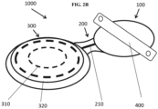
- FIG. 2B shows some components of a bone anchored hearing device 1000 comprising an (output) transducer 100 (an example of an electromagnetic vibrator, such as the one described above), a neck 200, and an antenna 300.
- the antenna 300 comprises a magnet assembly 310 and a receiving coil 320, both being embedded into silicone.
- the neck 200 comprises a reinforcement 210 in order to prevent breakage and/or tearing of the device at the neck.
- the transducer 100 is attached to a fixation band 400, which in turn may be fixed to the skull of the patient.
- the components shown in FIG. 2B may be wholly implantable.
- the compensator 400 may either be arranged within the antenna 300 or within the transducer 100 on a PCB electrically connected to the receiving coil 320.
- FIG. 3 shows a schematic illustration of a simplified electromagnetic vibrator 100 for a bone anchored hearing device comprising an electromagnet A (an example of the electromagnetic component) and an anchor B (an example of the vibrating component).
- Electromagnet A may be induced by the (amplified) electric input signal and, by means of a magnetic force following the electric input signal, i.e. the supply voltage, make anchor B move along a longitudinal direction, the longitudinal direction being indicated by the double arrow.
- the magnetic force between electromagnet A and anchor B is inversely proportional to the distance between A and B squared. I.e., when anchor B moves away from electromagnet A, the magnetic force gets weaker and when anchor B moves closer to electromagnet A, the magnetic force gets stronger.
- the proportionality may be exemplified in that if the distance gets doubled the magnetic force will be four times weaker and if the distance gets halved, the magnetic force will be four times stronger.
- the anchor will move in an asymmetrical way for a symmetrical signal, e.g. a sinusoidal signal.
- a symmetrical signal e.g. a sinusoidal signal.
- the asymmetrical movement leads to a distorted sinusoidal signal that may be measurable and/or hearable by the patient, e.g. when playing loud music.
- the distortion is small.
- the distortion increases, thereby possibly becoming measurable and/or hearable.
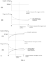
- FIG. 4 shows panels (A)-(D). All quantities shown in FIG. 4 are given in arbitrary units, meaning that a behavior of the quantities may only be interpreted qualitatively.
- Panel (A) shows a supply voltage of an electromagnetic vibrator (solid horizontal line) as a function of a distance between a magnet and an anchor of the electromagnetic vibrator for a constant supply voltage (a constant supply voltage profile).
- Panel (B) shows a magnetic force between the magnet and the anchor (solid line) as a function of the distance for a constant supply voltage as shown in panel (A). As can be seen in panel (B), as the distance increases from 0 to 1, the magnetic force decreases. Ideally, the magnetic force should be the same no matter where the magnet and/or anchor are (dashed horizontal line). The rest position of the anchor and/or the magnet is shown as a vertical, dashed line (panels (A) and (B)).
- Panel (C) shows a supply voltage (solid line) according to an exemplary embodiment as a function of the distance between the magnet and the anchor.
- the supply voltage is not constant as in panel (A), but varies depending on the distance. Specifically, as the distance increases from 0 to 1, the supply voltage increases as well.
- Panel (D) shows the magnetic force (solid grey line) as a function of the distance for a constant supply voltage as shown in panel (A), and the varied supply voltage (solid black line) shown in panel (C).
- the dependence of the supply voltage on the distance is the exact opposite of the dependence of the magnetic force on the distance.
- FIG. 5 shows a block diagram of some components of a bone anchored hearing device comprising a microphone ("MIC1"), a chip including an amplifier, a compensator, an input port for adding the compensation signal and an (electromagnetic) vibrator.
- the input port is connected to the compensator 400 which is also part of the bone anchored hearing device.
- the compensation signal may be applied at several stages along a path of the electric signal. As shown in FIG. 5 , the input port for adding the compensation signal may be located in between the chip including the amplifier and the electromagnetic vibrator.
- the compensation signal includes a supply voltage for the vibrator, and wherein the supply voltage is determined based on the uncompensated signal received from the chip.
- the compensator is connected to a memory which includes a measured distortion as a function of a supply voltage of the vibrator. In this example, the compensator is configured to determine the compensation signal based on the uncompensated signal and the measured distortion.
- FIG. 6A shows the magnetic force as a function of the displacement of the vibrating component for a real motion and for an ideal motion.
- FIG. 6A shows the same relationship which is shown in FIG. 4 , panel (B), whereby here, the x-axis shows the displacement of the vibrating component from its resting position (-30 to +30) instead of the distance between the magnet and the anchor (0 to 1).
- FIG. 6A shows a simulation of the magnetic force in the air gap between the magnet and/or coil and the anchor.
- the solid horizontal line shows the magnetic force of an ideal electromagnetic vibrator, the magnetic force being constant for a whole working range of the electromagnetic vibrator.
- the solid curved line shows a simulation of a movement due to the asymmetrical behavior of the electromagnetic vibrator (real motion).Thereby, when the vibrating component moves away from the electromagnetic component (positive displacement), the magnetic force gets weaker, and when the vibrating component moves closer to the electromagnetic component (negative displacement), the magnetic force gets stronger. A displacement of zero indicates the vibrating component being in its resting position.
- the magnetic field extends beyond the air gap and hence the magnetic field is more homogeneous.
- a deviation of the real motion from the ideal motion therefore is smaller than shown in FIG. 6A .
- the deviation of the magnetic force in an electromagnetic vibrator will be less than or equal to 10 %, in particular less than or equal to 5%.
- even such a relatively small deviation is unwanted as it might also induce measurable and/or hearable distortions.
- FIG. 6B shows the same magnetic forces shown in FIG. 6A , but further includes the compensation signal according to an exemplary embodiment as a function of the displacement of the vibrating component.
- FIG. 6B shows the same relationship which is shown in FIG. 4 , panel (D), whereby the x-axis shows the displacement of the vibrating component from its resting position (-30 to +30) instead of the distance between the magnet and the anchor (0 to 1).
- the compensation signal mirrors the asymmetrical movement of the anchor such that the compensation signal cancels out the asymmetric movement of the anchor, which alone would generate distortions.
- an actual movement of the anchor will be the same as a movement of the anchor in case of a constant magnetic force through the whole movement, i.e. will equal the ideal motion (solid horizontal line).
- a computer program comprising instructions which, when the program is executed by a computer, cause the computer to carry out (steps of) the method described above, in the 'detailed description of embodiments' and in the claims is furthermore provided by the present application.
- the functions may be stored on or encoded as one or more instructions or code on a tangible computer-readable medium.
- the computer readable medium includes computer storage media adapted to store a computer program comprising program codes, which when run on a processing system causes the data processing system to perform at least some (such as a majority or all) of the steps of the method described above, in the and in the claims.
- Such computer-readable media can comprise RAM, ROM, EEPROM, CD-ROM or other optical disk storage, magnetic disk storage or other magnetic storage devices, or any other medium that can be used to carry or store desired program code in the form of instructions or data structures and that can be accessed by a computer.
- Disk and disc includes compact disc (CD), laser disc, optical disc, digital versatile disc (DVD), floppy disk and Blu-ray disc where disks usually reproduce data magnetically, while discs reproduce data optically with lasers. Combinations of the above should also be included within the scope of computer-readable media.
- the computer program can also be transmitted via a transmission medium such as a wired or wireless link or a network, e.g. the Internet, and loaded into a data processing system for being executed at a location different from that of the tangible medium.
- a transmission medium such as a wired or wireless link or a network, e.g. the Internet
- a data processing system comprising a processor adapted to execute the computer program for causing the processor to perform at least some (such as a majority or all) of the steps of the method described above and in the claims is provided.
Landscapes
- Physics & Mathematics (AREA)
- Health & Medical Sciences (AREA)
- General Health & Medical Sciences (AREA)
- Otolaryngology (AREA)
- Engineering & Computer Science (AREA)
- Acoustics & Sound (AREA)
- Signal Processing (AREA)
- Neurosurgery (AREA)
- Electromagnetism (AREA)
- Details Of Audible-Bandwidth Transducers (AREA)
Claims (11)
- Knochenverankertes Hörgerät (100), umfassend:- einen Eingangswandler, der dazu konfiguriert ist, ein elektrisches Eingangssignal bereitzustellen, das Schall einer Umgebung eines Benutzers des knochenverankerten Hörgeräts darstellt;- eine Signalverarbeitungseinheit, die dazu konfiguriert ist, das elektrische Eingangssignal zu verarbeiten und ein verarbeitetes elektrisches Signal bereitzustellen;- einen elektromagnetischen Vibrator (100) zum Erzeugen einer Vibration, um Schall durch einen Knochen eines Benutzers an ein Ohr des Benutzers auf Grundlage des verarbeiteten elektrischen Signals zu übertragen; und- einen Kompensator, der dazu konfiguriert ist, ein Kompensationssignal zum mindestens teilweisen Kompensieren einer Verzerrung in der Vibration des elektromagnetischen Vibrators (100) zu bestimmen, wobei die Kompensation der Verzerrung auf einer Abhängigkeit einer Antriebskraft, die auf eine vibrierende Komponente (A) des elektromagnetischen Vibrators (100) einwirkt, von einer Verschiebung der vibrierenden Komponente (A) basiert.
- Knochenverankertes Hörgerät nach Anspruch 1, wobei die Verzerrung eine Verzerrung aufgrund eines asymmetrischen Verhaltens des elektromagnetischen Vibrators (100) ist.
- Knochenverankertes Hörgerät nach einem der vorhergehenden Ansprüche, wobei der Kompensator dazu konfiguriert ist, ein unkompensiertes Signal zu empfangen und/oder das kompensierte Signal an den elektromagnetischen Vibrator bereitzustellen, um die Verzerrung in der Vibration des elektromagnetischen Vibrators mindestens teilweise zu kompensieren.
- Knochenverankertes Hörgerät nach Anspruch 3, wobei das Kompensationssignal von einer Versorgungsspannung des elektromagnetischen Vibrators, insbesondere einer Spule (7) des elektromagnetischen Vibrators, umfasst ist.
- Knochenverankertes Hörgerät nach einem der vorhergehenden Ansprüche, wobei der elektromagnetische Vibrator (100) ein Vibrator mit variabler Reluktanz ist.
- Knochenverankertes Hörgerät nach einem der vorhergehenden Ansprüche, wobei der elektromagnetische Vibrator eines oder mehrere der Folgenden umfasst:- einen Magneten (8) und/oder eine Spule (7) zum Erzeugen von Vibrationen, um Schall durch den Knochen an das Ohr zu übertragen;- einen Anker (A) zum Verbinden des elektromagnetischen Vibrators mit einem Aufsatz (30) oder Implantat; und/oder- einen Luftspalt zwischen dem Magneten (8) und/oder der Spule (7) und dem Anker (A).
- Knochenverankertes Hörgerät nach einem der vorhergehenden Ansprüche, ferner umfassend eines oder mehrere der Folgenden:- ein Implantat zur Implantation in den Knochen;- einen Aufsatz (A) zur Verbindung mit dem Implantat;- eine Empfangsspule (320) zum Empfangen elektromagnetischer Signale; und/oder- einen Verstärker zum Verstärken eines elektrischen Signals.
- Knochenverankertes Hörgerät nach einem der vorhergehenden Ansprüche, wobei der Kompensator zu einem oder mehreren der Folgenden konfiguriert ist:- Modifizieren einer Versorgungsspannung des elektromagnetischen Vibrators (100); und/oder- Modifizieren der Versorgungsspannung des elektromagnetischen Vibrators (100) in Abhängigkeit von einer durch einen Sensor gemessenen Verschiebung der vibrierenden Komponente (7, 8) des elektromagnetischen Vibrators (100).
- Signalverarbeitungsverfahren für ein knochenverankertes Hörgerät (1000), insbesondere ein knochenverankertes Hörgerät nach einem der Ansprüche 1 bis 8, wobei das Verfahren Folgendes umfasst:- Bereitstellen, durch einen Eingangswandler, eines elektrischen Eingangssignals, das Schall einer Umgebung eines Benutzers des knochenverankerten Hörgeräts darstellt;- Verarbeiten, durch eine Signalverarbeitungseinheit, des elektrischen Eingangssignals und Bereitstellen eines verarbeiteten elektrischen Signals;- Erzeugen, durch einen elektromagnetischen Vibrator (100), einer Vibration auf Grundlage des verarbeiteten elektrischen Signals, um Schall durch einen Knochen des Benutzers an ein Ohr des Benutzers zu übertragen; und- mindestens teilweises Kompensieren, durch einen Kompensator, der ein Kompensationssignal bestimmt, einer Verzerrung in der Vibration des elektromagnetischen Vibrators (100), wobei die Kompensation der Verzerrung auf einer Abhängigkeit einer Antriebskraft, die auf eine vibrierende Komponente (A) des elektromagnetischen Vibrators (100) einwirkt, von einer Verschiebung der vibrierenden Komponente (A) basiert.
- Signalverarbeitungsverfahren nach Anspruch 9, wobei das Kompensieren Folgendes umfasst:
Kompensieren einer Verzerrung aufgrund eines asymmetrischen Verhaltens des elektromagnetischen Vibrators (100). - Signalverarbeitungsverfahren nach Anspruch 9 oder 10, wobei das Kompensieren Folgendes umfasst:- Modifizieren einer Versorgungsspannung des elektromagnetischen Vibrators (100); und/oder- Modifizieren der Versorgungsspannung des elektromagnetischen Vibrators (100) in Abhängigkeit von einer durch einen Sensor gemessenen Verschiebung der vibrierenden Komponente des elektromagnetischen Vibrators (100).
Priority Applications (1)
| Application Number | Priority Date | Filing Date | Title |
|---|---|---|---|
| EP24209706.1A EP4492818A3 (de) | 2020-10-23 | 2021-10-06 | Verzerrungskompensation für knochenverankerte hörvorrichtung |
Applications Claiming Priority (1)
| Application Number | Priority Date | Filing Date | Title |
|---|---|---|---|
| EP20203503 | 2020-10-23 |
Related Child Applications (3)
| Application Number | Title | Priority Date | Filing Date |
|---|---|---|---|
| EP24209706.1A Division EP4492818A3 (de) | 2020-10-23 | 2021-10-06 | Verzerrungskompensation für knochenverankerte hörvorrichtung |
| EP24209706.1A Previously-Filed-Application EP4492818A3 (de) | 2020-10-23 | 2021-10-06 | Verzerrungskompensation für knochenverankerte hörvorrichtung |
| EP24209706.1A Division-Into EP4492818A3 (de) | 2020-10-23 | 2021-10-06 | Verzerrungskompensation für knochenverankerte hörvorrichtung |
Publications (3)
| Publication Number | Publication Date |
|---|---|
| EP3989602A1 EP3989602A1 (de) | 2022-04-27 |
| EP3989602C0 EP3989602C0 (de) | 2024-12-11 |
| EP3989602B1 true EP3989602B1 (de) | 2024-12-11 |
Family
ID=73013352
Family Applications (2)
| Application Number | Title | Priority Date | Filing Date |
|---|---|---|---|
| EP21201181.1A Active EP3989602B1 (de) | 2020-10-23 | 2021-10-06 | Verzerrungskompensation für ein knochenverankertes hörgerät |
| EP24209706.1A Pending EP4492818A3 (de) | 2020-10-23 | 2021-10-06 | Verzerrungskompensation für knochenverankerte hörvorrichtung |
Family Applications After (1)
| Application Number | Title | Priority Date | Filing Date |
|---|---|---|---|
| EP24209706.1A Pending EP4492818A3 (de) | 2020-10-23 | 2021-10-06 | Verzerrungskompensation für knochenverankerte hörvorrichtung |
Country Status (4)
| Country | Link |
|---|---|
| US (1) | US11606652B2 (de) |
| EP (2) | EP3989602B1 (de) |
| CN (1) | CN114501277A (de) |
| AU (1) | AU2021245240A1 (de) |
Family Cites Families (7)
| Publication number | Priority date | Publication date | Assignee | Title |
|---|---|---|---|---|
| JP5191750B2 (ja) * | 2008-01-25 | 2013-05-08 | 川崎重工業株式会社 | 音響装置 |
| SE536254C2 (sv) * | 2010-11-12 | 2013-07-23 | Osseofon Ab | Anpassningsnät till benledningsvibrator |
| US11540066B2 (en) * | 2011-12-23 | 2022-12-27 | Shenzhen Shokz Co., Ltd. | Bone conduction speaker and compound vibration device thereof |
| US9301071B2 (en) * | 2013-03-12 | 2016-03-29 | Quantance, Inc. | Reducing audio distortion in an audio system |
| CN105721973B (zh) * | 2016-01-26 | 2019-04-05 | 王泽玲 | 一种骨传导耳机及其音频处理方法 |
| US11035830B2 (en) * | 2017-06-23 | 2021-06-15 | Cochlear Limited | Electromagnetic transducer with dual flux |
| US11245984B1 (en) * | 2020-07-15 | 2022-02-08 | Facebook Technologies, Llc | Audio system using individualized sound profiles |
-
2021
- 2021-10-06 EP EP21201181.1A patent/EP3989602B1/de active Active
- 2021-10-06 EP EP24209706.1A patent/EP4492818A3/de active Pending
- 2021-10-08 AU AU2021245240A patent/AU2021245240A1/en active Pending
- 2021-10-22 US US17/508,270 patent/US11606652B2/en active Active
- 2021-10-22 CN CN202111233161.1A patent/CN114501277A/zh active Pending
Also Published As
| Publication number | Publication date |
|---|---|
| CN114501277A (zh) | 2022-05-13 |
| AU2021245240A1 (en) | 2022-05-12 |
| EP3989602C0 (de) | 2024-12-11 |
| US11606652B2 (en) | 2023-03-14 |
| EP4492818A3 (de) | 2025-04-02 |
| EP3989602A1 (de) | 2022-04-27 |
| EP4492818A2 (de) | 2025-01-15 |
| US20220132256A1 (en) | 2022-04-28 |
Similar Documents
| Publication | Publication Date | Title |
|---|---|---|
| EP3321933B1 (de) | Lineares resonanzaktuatorsteuergerät | |
| KR20220113969A (ko) | 소리출력장치 | |
| US11109166B2 (en) | Hearing device comprising direct sound compensation | |
| EP2393309B1 (de) | Vorrichtung und Verfahren zur Anwendung eines Schwingungssignals an einen Knochen des menschlichen Schädels | |
| RU2427100C2 (ru) | Плоский громкоговоритель и способ для установки режима колебаний колебательной системы | |
| US7556597B2 (en) | Active vibration attenuation for implantable microphone | |
| US20220210581A1 (en) | Hearing aid comprising a feedback control system | |
| JP7738915B2 (ja) | 聴覚補助装置 | |
| WO2009137360A1 (en) | Fluid cushion support for implantable device | |
| US12302069B2 (en) | Hearing aid including a piezo assembly and an electromagnetic assembly | |
| EP3989602B1 (de) | Verzerrungskompensation für ein knochenverankertes hörgerät | |
| EP3955595B1 (de) | Hörgerät mit sensor zum detektieren einer ausrichtung der hörgerätemikrofone | |
| JPWO2020026944A1 (ja) | 音響出力装置 | |
| US11881201B2 (en) | Control apparatus, loudspeaker apparatus, and audio output method | |
| KR20230131221A (ko) | 보청기 | |
| US10334356B2 (en) | Microphone for a hearing aid | |
| US20250392854A1 (en) | Active echo canceller for a hearing device | |
| US20230117736A1 (en) | Electromagnetic vibrator for generating a vibration in order to transmit sound through a bone of a skull of a user to an ear of the user and a bone anchored hearing device | |
| US12621613B2 (en) | Method of detecting a sudden change in a feedback/echo path of a hearing aid | |
| US20240348997A1 (en) | Bone anchored hearing aid device unit | |
| HK40035679A (en) | Hearing assistance device | |
| CN119922480A (zh) | 扬声器的过大振幅抑制装置 |
Legal Events
| Date | Code | Title | Description |
|---|---|---|---|
| PUAI | Public reference made under article 153(3) epc to a published international application that has entered the european phase |
Free format text: ORIGINAL CODE: 0009012 |
|
| STAA | Information on the status of an ep patent application or granted ep patent |
Free format text: STATUS: THE APPLICATION HAS BEEN PUBLISHED |
|
| AK | Designated contracting states |
Kind code of ref document: A1 Designated state(s): AL AT BE BG CH CY CZ DE DK EE ES FI FR GB GR HR HU IE IS IT LI LT LU LV MC MK MT NL NO PL PT RO RS SE SI SK SM TR |
|
| STAA | Information on the status of an ep patent application or granted ep patent |
Free format text: STATUS: REQUEST FOR EXAMINATION WAS MADE |
|
| 17P | Request for examination filed |
Effective date: 20221027 |
|
| RBV | Designated contracting states (corrected) |
Designated state(s): AL AT BE BG CH CY CZ DE DK EE ES FI FR GB GR HR HU IE IS IT LI LT LU LV MC MK MT NL NO PL PT RO RS SE SI SK SM TR |
|
| GRAP | Despatch of communication of intention to grant a patent |
Free format text: ORIGINAL CODE: EPIDOSNIGR1 |
|
| STAA | Information on the status of an ep patent application or granted ep patent |
Free format text: STATUS: GRANT OF PATENT IS INTENDED |
|
| RIC1 | Information provided on ipc code assigned before grant |
Ipc: H04R 25/00 20060101ALN20240327BHEP Ipc: H04R 3/08 20060101ALI20240327BHEP Ipc: H04R 3/00 20060101AFI20240327BHEP |
|
| RIC1 | Information provided on ipc code assigned before grant |
Ipc: H04R 25/00 20060101ALN20240409BHEP Ipc: H04R 3/08 20060101ALI20240409BHEP Ipc: H04R 3/00 20060101AFI20240409BHEP |
|
| INTG | Intention to grant announced |
Effective date: 20240425 |
|
| GRAJ | Information related to disapproval of communication of intention to grant by the applicant or resumption of examination proceedings by the epo deleted |
Free format text: ORIGINAL CODE: EPIDOSDIGR1 |
|
| STAA | Information on the status of an ep patent application or granted ep patent |
Free format text: STATUS: REQUEST FOR EXAMINATION WAS MADE |
|
| GRAP | Despatch of communication of intention to grant a patent |
Free format text: ORIGINAL CODE: EPIDOSNIGR1 |
|
| STAA | Information on the status of an ep patent application or granted ep patent |
Free format text: STATUS: GRANT OF PATENT IS INTENDED |
|
| INTC | Intention to grant announced (deleted) | ||
| RIC1 | Information provided on ipc code assigned before grant |
Ipc: H04R 25/00 20060101ALN20240612BHEP Ipc: H04R 3/08 20060101ALI20240612BHEP Ipc: H04R 3/00 20060101AFI20240612BHEP |
|
| INTG | Intention to grant announced |
Effective date: 20240704 |
|
| GRAS | Grant fee paid |
Free format text: ORIGINAL CODE: EPIDOSNIGR3 |
|
| GRAA | (expected) grant |
Free format text: ORIGINAL CODE: 0009210 |
|
| STAA | Information on the status of an ep patent application or granted ep patent |
Free format text: STATUS: THE PATENT HAS BEEN GRANTED |
|
| AK | Designated contracting states |
Kind code of ref document: B1 Designated state(s): AL AT BE BG CH CY CZ DE DK EE ES FI FR GB GR HR HU IE IS IT LI LT LU LV MC MK MT NL NO PL PT RO RS SE SI SK SM TR |
|
| REG | Reference to a national code |
Ref country code: GB Ref legal event code: FG4D |
|
| REG | Reference to a national code |
Ref country code: CH Ref legal event code: EP |
|
| REG | Reference to a national code |
Ref country code: IE Ref legal event code: FG4D |
|
| REG | Reference to a national code |
Ref country code: DE Ref legal event code: R096 Ref document number: 602021023182 Country of ref document: DE |
|
| U01 | Request for unitary effect filed |
Effective date: 20241217 |
|
| U07 | Unitary effect registered |
Designated state(s): AT BE BG DE DK EE FI FR IT LT LU LV MT NL PT RO SE SI Effective date: 20250110 |
|
| PG25 | Lapsed in a contracting state [announced via postgrant information from national office to epo] |
Ref country code: HR Free format text: LAPSE BECAUSE OF FAILURE TO SUBMIT A TRANSLATION OF THE DESCRIPTION OR TO PAY THE FEE WITHIN THE PRESCRIBED TIME-LIMIT Effective date: 20241211 |
|
| PG25 | Lapsed in a contracting state [announced via postgrant information from national office to epo] |
Ref country code: ES Free format text: LAPSE BECAUSE OF FAILURE TO SUBMIT A TRANSLATION OF THE DESCRIPTION OR TO PAY THE FEE WITHIN THE PRESCRIBED TIME-LIMIT Effective date: 20241211 |
|
| PG25 | Lapsed in a contracting state [announced via postgrant information from national office to epo] |
Ref country code: NO Free format text: LAPSE BECAUSE OF FAILURE TO SUBMIT A TRANSLATION OF THE DESCRIPTION OR TO PAY THE FEE WITHIN THE PRESCRIBED TIME-LIMIT Effective date: 20250311 |
|
| PG25 | Lapsed in a contracting state [announced via postgrant information from national office to epo] |
Ref country code: GR Free format text: LAPSE BECAUSE OF FAILURE TO SUBMIT A TRANSLATION OF THE DESCRIPTION OR TO PAY THE FEE WITHIN THE PRESCRIBED TIME-LIMIT Effective date: 20250312 |
|
| PG25 | Lapsed in a contracting state [announced via postgrant information from national office to epo] |
Ref country code: RS Free format text: LAPSE BECAUSE OF FAILURE TO SUBMIT A TRANSLATION OF THE DESCRIPTION OR TO PAY THE FEE WITHIN THE PRESCRIBED TIME-LIMIT Effective date: 20250311 |
|
| PG25 | Lapsed in a contracting state [announced via postgrant information from national office to epo] |
Ref country code: SM Free format text: LAPSE BECAUSE OF FAILURE TO SUBMIT A TRANSLATION OF THE DESCRIPTION OR TO PAY THE FEE WITHIN THE PRESCRIBED TIME-LIMIT Effective date: 20241211 |
|
| PG25 | Lapsed in a contracting state [announced via postgrant information from national office to epo] |
Ref country code: PL Free format text: LAPSE BECAUSE OF FAILURE TO SUBMIT A TRANSLATION OF THE DESCRIPTION OR TO PAY THE FEE WITHIN THE PRESCRIBED TIME-LIMIT Effective date: 20241211 |
|
| PG25 | Lapsed in a contracting state [announced via postgrant information from national office to epo] |
Ref country code: IS Free format text: LAPSE BECAUSE OF FAILURE TO SUBMIT A TRANSLATION OF THE DESCRIPTION OR TO PAY THE FEE WITHIN THE PRESCRIBED TIME-LIMIT Effective date: 20250411 |
|
| PG25 | Lapsed in a contracting state [announced via postgrant information from national office to epo] |
Ref country code: SK Free format text: LAPSE BECAUSE OF FAILURE TO SUBMIT A TRANSLATION OF THE DESCRIPTION OR TO PAY THE FEE WITHIN THE PRESCRIBED TIME-LIMIT Effective date: 20241211 |
|
| PG25 | Lapsed in a contracting state [announced via postgrant information from national office to epo] |
Ref country code: CZ Free format text: LAPSE BECAUSE OF FAILURE TO SUBMIT A TRANSLATION OF THE DESCRIPTION OR TO PAY THE FEE WITHIN THE PRESCRIBED TIME-LIMIT Effective date: 20241211 |
|
| PGFP | Annual fee paid to national office [announced via postgrant information from national office to epo] |
Ref country code: GB Payment date: 20250926 Year of fee payment: 5 |
|
| PLBE | No opposition filed within time limit |
Free format text: ORIGINAL CODE: 0009261 |
|
| STAA | Information on the status of an ep patent application or granted ep patent |
Free format text: STATUS: NO OPPOSITION FILED WITHIN TIME LIMIT |
|
| REG | Reference to a national code |
Ref country code: CH Ref legal event code: L10 Free format text: ST27 STATUS EVENT CODE: U-0-0-L10-L00 (AS PROVIDED BY THE NATIONAL OFFICE) Effective date: 20251022 |
|
| REG | Reference to a national code |
Ref country code: CH Ref legal event code: U11 Free format text: ST27 STATUS EVENT CODE: U-0-0-U10-U11 (AS PROVIDED BY THE NATIONAL OFFICE) Effective date: 20251101 |
|
| 26N | No opposition filed |
Effective date: 20250912 |
|
| U20 | Renewal fee for the european patent with unitary effect paid |
Year of fee payment: 5 Effective date: 20251031 |
|
| PGFP | Annual fee paid to national office [announced via postgrant information from national office to epo] |
Ref country code: CH Payment date: 20251101 Year of fee payment: 5 |