EP3989431A1 - Dielectric elastomer transducer - Google Patents
Dielectric elastomer transducer Download PDFInfo
- Publication number
- EP3989431A1 EP3989431A1 EP20831571.3A EP20831571A EP3989431A1 EP 3989431 A1 EP3989431 A1 EP 3989431A1 EP 20831571 A EP20831571 A EP 20831571A EP 3989431 A1 EP3989431 A1 EP 3989431A1
- Authority
- EP
- European Patent Office
- Prior art keywords
- dielectric elastomer
- particle size
- carbon black
- peak
- range
- Prior art date
- Legal status (The legal status is an assumption and is not a legal conclusion. Google has not performed a legal analysis and makes no representation as to the accuracy of the status listed.)
- Withdrawn
Links
- 229920002595 Dielectric elastomer Polymers 0.000 title claims abstract description 35
- 239000002245 particle Substances 0.000 claims abstract description 38
- 239000006229 carbon black Substances 0.000 claims abstract description 30
- 238000002296 dynamic light scattering Methods 0.000 claims abstract description 16
- 239000011230 binding agent Substances 0.000 claims abstract description 4
- 235000019241 carbon black Nutrition 0.000 description 22
- 238000005259 measurement Methods 0.000 description 20
- 239000000463 material Substances 0.000 description 8
- LFQSCWFLJHTTHZ-UHFFFAOYSA-N Ethanol Chemical compound CCO LFQSCWFLJHTTHZ-UHFFFAOYSA-N 0.000 description 6
- KFZMGEQAYNKOFK-UHFFFAOYSA-N Isopropanol Chemical compound CC(C)O KFZMGEQAYNKOFK-UHFFFAOYSA-N 0.000 description 6
- OKTJSMMVPCPJKN-UHFFFAOYSA-N Carbon Chemical compound [C] OKTJSMMVPCPJKN-UHFFFAOYSA-N 0.000 description 5
- 239000011521 glass Substances 0.000 description 4
- 239000000243 solution Substances 0.000 description 4
- 229910052799 carbon Inorganic materials 0.000 description 3
- 230000000052 comparative effect Effects 0.000 description 3
- 239000006185 dispersion Substances 0.000 description 3
- 239000002904 solvent Substances 0.000 description 3
- 239000000126 substance Substances 0.000 description 3
- PPBRXRYQALVLMV-UHFFFAOYSA-N Styrene Chemical compound C=CC1=CC=CC=C1 PPBRXRYQALVLMV-UHFFFAOYSA-N 0.000 description 2
- 239000000945 filler Substances 0.000 description 2
- 238000010248 power generation Methods 0.000 description 2
- 238000002525 ultrasonication Methods 0.000 description 2
- BQCADISMDOOEFD-UHFFFAOYSA-N Silver Chemical compound [Ag] BQCADISMDOOEFD-UHFFFAOYSA-N 0.000 description 1
- 239000002042 Silver nanowire Substances 0.000 description 1
- 229920000800 acrylic rubber Polymers 0.000 description 1
- 239000002041 carbon nanotube Substances 0.000 description 1
- 229910021393 carbon nanotube Inorganic materials 0.000 description 1
- 239000000470 constituent Substances 0.000 description 1
- 230000008602 contraction Effects 0.000 description 1
- 239000012895 dilution Substances 0.000 description 1
- 238000010790 dilution Methods 0.000 description 1
- 239000002270 dispersing agent Substances 0.000 description 1
- 230000005489 elastic deformation Effects 0.000 description 1
- 229920001971 elastomer Polymers 0.000 description 1
- 239000000806 elastomer Substances 0.000 description 1
- 238000002474 experimental method Methods 0.000 description 1
- 230000002349 favourable effect Effects 0.000 description 1
- 239000004519 grease Substances 0.000 description 1
- 238000009499 grossing Methods 0.000 description 1
- 239000011810 insulating material Substances 0.000 description 1
- 238000000034 method Methods 0.000 description 1
- 239000002070 nanowire Substances 0.000 description 1
- 230000002093 peripheral effect Effects 0.000 description 1
- 229920000058 polyacrylate Polymers 0.000 description 1
- 229920000642 polymer Polymers 0.000 description 1
- 239000011347 resin Substances 0.000 description 1
- 229920005989 resin Polymers 0.000 description 1
- 238000000790 scattering method Methods 0.000 description 1
- 229920002379 silicone rubber Polymers 0.000 description 1
Images
Classifications
-
- H—ELECTRICITY
- H02—GENERATION; CONVERSION OR DISTRIBUTION OF ELECTRIC POWER
- H02N—ELECTRIC MACHINES NOT OTHERWISE PROVIDED FOR
- H02N11/00—Generators or motors not provided for elsewhere; Alleged perpetua mobilia obtained by electric or magnetic means
-
- C—CHEMISTRY; METALLURGY
- C09—DYES; PAINTS; POLISHES; NATURAL RESINS; ADHESIVES; COMPOSITIONS NOT OTHERWISE PROVIDED FOR; APPLICATIONS OF MATERIALS NOT OTHERWISE PROVIDED FOR
- C09C—TREATMENT OF INORGANIC MATERIALS, OTHER THAN FIBROUS FILLERS, TO ENHANCE THEIR PIGMENTING OR FILLING PROPERTIES ; PREPARATION OF CARBON BLACK ; PREPARATION OF INORGANIC MATERIALS WHICH ARE NO SINGLE CHEMICAL COMPOUNDS AND WHICH ARE MAINLY USED AS PIGMENTS OR FILLERS
- C09C1/00—Treatment of specific inorganic materials other than fibrous fillers; Preparation of carbon black
- C09C1/44—Carbon
- C09C1/48—Carbon black
-
- B—PERFORMING OPERATIONS; TRANSPORTING
- B06—GENERATING OR TRANSMITTING MECHANICAL VIBRATIONS IN GENERAL
- B06B—METHODS OR APPARATUS FOR GENERATING OR TRANSMITTING MECHANICAL VIBRATIONS OF INFRASONIC, SONIC, OR ULTRASONIC FREQUENCY, e.g. FOR PERFORMING MECHANICAL WORK IN GENERAL
- B06B1/00—Methods or apparatus for generating mechanical vibrations of infrasonic, sonic, or ultrasonic frequency
- B06B1/02—Methods or apparatus for generating mechanical vibrations of infrasonic, sonic, or ultrasonic frequency making use of electrical energy
- B06B1/0292—Electrostatic transducers, e.g. electret-type
-
- H—ELECTRICITY
- H10—SEMICONDUCTOR DEVICES; ELECTRIC SOLID-STATE DEVICES NOT OTHERWISE PROVIDED FOR
- H10N—ELECTRIC SOLID-STATE DEVICES NOT OTHERWISE PROVIDED FOR
- H10N30/00—Piezoelectric or electrostrictive devices
- H10N30/20—Piezoelectric or electrostrictive devices with electrical input and mechanical output, e.g. functioning as actuators or vibrators
- H10N30/206—Piezoelectric or electrostrictive devices with electrical input and mechanical output, e.g. functioning as actuators or vibrators using only longitudinal or thickness displacement, e.g. d33 or d31 type devices
-
- H—ELECTRICITY
- H10—SEMICONDUCTOR DEVICES; ELECTRIC SOLID-STATE DEVICES NOT OTHERWISE PROVIDED FOR
- H10N—ELECTRIC SOLID-STATE DEVICES NOT OTHERWISE PROVIDED FOR
- H10N30/00—Piezoelectric or electrostrictive devices
- H10N30/80—Constructional details
- H10N30/87—Electrodes or interconnections, e.g. leads or terminals
- H10N30/877—Conductive materials
- H10N30/878—Conductive materials the principal material being non-metallic, e.g. oxide or carbon based
-
- C—CHEMISTRY; METALLURGY
- C01—INORGANIC CHEMISTRY
- C01P—INDEXING SCHEME RELATING TO STRUCTURAL AND PHYSICAL ASPECTS OF SOLID INORGANIC COMPOUNDS
- C01P2004/00—Particle morphology
- C01P2004/51—Particles with a specific particle size distribution
- C01P2004/53—Particles with a specific particle size distribution bimodal size distribution
-
- C—CHEMISTRY; METALLURGY
- C01—INORGANIC CHEMISTRY
- C01P—INDEXING SCHEME RELATING TO STRUCTURAL AND PHYSICAL ASPECTS OF SOLID INORGANIC COMPOUNDS
- C01P2006/00—Physical properties of inorganic compounds
- C01P2006/40—Electric properties
Definitions
- the present invention relates to a dielectric elastomer transducer.
- a dielectric elastomer transducer which includes a dielectric elastomer layer sandwiched between a pair of electrode layers, is expected to find a variety of applications such as actuation, power generation and sensing.
- An example of a conventional dielectric elastomer transducer is disclosed in Patent Document 1.
- silver nanowires, carbon nanowires, carbon nanotubes, carbon nanofillers, etc. are recited as the constituent materials of the electrode layers.
- Patent Document 1 JP-A-2017-34923
- Dielectric elastomer transducers are generally used on the premise that the dielectric elastomer layer exhibits a high stretchability.
- the electrode layers need to have enough stretchability to follow the dielectric elastomer layer.
- the electrode layers are the parts to which an electric charge (voltage) is applied, and it is necessary to avoid the electrode layers becoming electrically insulated due to expansion and contraction.
- the present invention has been conceived in view of the circumstances described above and aims to provide a dielectric elastomer transducer that achieves both stretchability and electrical conductivity.
- a dielectric elastomer transducer provided by the present invention includes a dielectric elastomer layer, and a pair of electrode layers sandwiching the dielectric elastomer layer.
- the electrode layers contain a binder and carbon black.
- the carbon black has a particle size distribution as measured by dynamic light scattering in which not less than 95% falls in a range of 0.15 to 8.0 ⁇ m.
- the carbon black has a particle size as measured by laser scattering ranging from 0.4 to 50 ⁇ m.
- the particle size distribution of the carbon black as measured by dynamic light scattering has a first peak that falls in a first range of 0.15 to 1.0 ⁇ m and a second peak that falls in a second range of 1.0 ⁇ m to 8.0 ⁇ m.
- the second peak is higher than the first peak.
- the prevent invention provides a dielectric elastomer transducer that achieves both stretchability and electrical conductivity.
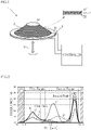
- Fig. 1 shows an example of a dielectric elastomer transducer according to the present invention.
- the illustrated transducer 1 includes a dielectric elastomer element 2, a support 3 and a rod 4.
- the dielectric elastomer element 2 has a dielectric elastomer layer 21 and a pair of electrode layers 22.
- the dielectric elastomer layer 21 needs to be elastically deformable and have a high dielectric strength.
- Preferable examples of such a material for the dielectric elastomer layer 21 include, but not limited to, silicone elastomers, acrylic elastomers and styrene elastomers.
- the dielectric elastomer layer 21 has a circular or annular shape in the illustrated example, but is not limited to this.
- the pair of electrode layers 22, which sandwich the dielectric elastomer layer 21, are subjected to voltage application.
- the electrode layers 22 are made of a material that is electrically conductive and also elastically deformable so as to follow the elastic deformation of the dielectric elastomer layer 21. Examples of such a material include an elastically deformable material mixed with a filler that imparts conductivity. Examples of the elastically deformable material include polymer-based materials and grease materials. In the present embodiment, carbon black having the particle size distribution described later, for example, is used as the filler.
- the electrode layers 22 have a circular or annular shape in the illustrated example, but are not limited to this.
- the support 3 is a support structure that supports the dielectric elastomer element 2 in a desired state.
- the support 3 includes a support disk 30 and a support ring 31.
- the support disk 30 and the support ring 31 are made of an insulating material such as resin.
- the support disk 30 supports the central part of the dielectric elastomer element 2.
- the support ring 31 supports the peripheral part of the dielectric elastomer element 2.
- the rod 4 is a shaft that outputs a driving force when the transducer 1 is used as an actuator and receives an external force when the transducer 1 is used as a power generation device.
- the rod 4 is fixed to the support disk 30 at one end.
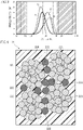
- Fig. 2 shows the particle size distribution of carbon black used for the electrode layers 22, as measured by dynamic light scattering.
- Fig. 3 shows the particle size distribution as measured by laser scattering. Measurements by dynamic light scattering and laser scattering were performed as follows.
- a carbon black dispersion or solution was prepared by dispersing carbon black in CyH as a solvent.
- Example A uses VULCAN XCR72R available from CABOT
- Example B uses Blackpearls 2000 available from CABOT.
- Example A has a nominal particle size of 30 nm and a nominal specific surface area of 254 m 2 /g.
- Example B has a nominal particle size of 15 nm and a nominal specific surface area of 1475 m 2 /g.
- Comparative Example C uses #3030B available from Mitsubishi Chemical Corporation, and Comparative Example D uses TOKABLACK #5500 available from Tokai Carbon Co, Ltd.
- Example C has a nominal particle size of 55 nm and a nominal specific surface area of 29 m 2 /g.
- Example D has a nominal particle size of 25 nm and a nominal specific surface area of 225 m 2 /g.
- not less than 95% falls in the range of 0.15 to 8.0 ⁇ m in the distribution of the particle size D1 as measured by dynamic light scattering.
- Not less than 95% falling in the above-mentioned range means that in the particle size measurement of the objects, the frequency of the measurement results falling in the above-mentioned range is not less than 95%.
- the particle size D2 as measured by laser scattering ranges from 0.4 to 50 ⁇ m.
- the distribution of the particle size D1 as measured by dynamic light scattering has a first peak that falls in a first range of 0.15 to 1.0 ⁇ m and a second peak that falls in a second range of 1.0 to 8.0 ⁇ m.
- the second peak is higher than the first peak.
- Examples C and D each have a peak that falls in the second range but have no peak in the first range.
- Examples A, B and Comparative Examples C and D not less than 95% falls in the range of 0.15 to 8.0 ⁇ m in the distribution of the particle size D1 as measured by dynamic light scattering, and the particle size D2 as measured by laser scattering ranges from 0.4 to 50 ⁇ m. Moreover, the distribution of the particle size D1 as measured by dynamic light scattering has a first peak that falls in a first range of 0.15 to 1.0 ⁇ m and a second peak that falls in a second range of 1.0 to 8.0 ⁇ m. Experiments by the inventors confirmed that Examples A and B having the above features provide a high conductivity and a high elasticity.
- the electrode layers 22 are considered to have an internal structure as shown in Fig. 4 .
- the electrode layers 22 contain carbon blacks 221 and 222 in a binder 220.
- Carbon blacks 221 each are an aggregate, formed by e.g. cohesion, of a plurality of carbon black particles and correspond to the particle size D1 of the second peak in the second range mentioned above.
- Carbon blacks 222 each are a single carbon black particle or an aggregate of a relatively small number of carbon black particles and correspond to the particle size D1 of the first peak in the first range mentioned above.
- the gaps between carbon blacks 221 having a relatively large particle size D1 are filled with carbon blacks 222 having a relatively small particle size D1.
- the second peak in the second range being higher than the first peak in the first range means that carbon blacks 221 are contained in a larger amount than carbon blacks 222. Containing carbon blacks 221, which contribute to fundamental conduction and maintaining elasticity of the electrode layers 22, in a large amount is favorable for improving conductivity and elasticity.
- the dielectric elastomer transducer according to the present invention is not limited to the foregoing embodiments.
- the specific configuration of each part of the dielectric elastomer transducer according to the present invention may be varied in design in many ways.
Landscapes
- Chemical & Material Sciences (AREA)
- Organic Chemistry (AREA)
- Engineering & Computer Science (AREA)
- Mechanical Engineering (AREA)
- Compositions Of Macromolecular Compounds (AREA)
Abstract
Description
- The present invention relates to a dielectric elastomer transducer.
- A dielectric elastomer transducer, which includes a dielectric elastomer layer sandwiched between a pair of electrode layers, is expected to find a variety of applications such as actuation, power generation and sensing. An example of a conventional dielectric elastomer transducer is disclosed in
Patent Document 1. In this document, silver nanowires, carbon nanowires, carbon nanotubes, carbon nanofillers, etc. are recited as the constituent materials of the electrode layers. - Patent Document 1:
JP-A-2017-34923 - Dielectric elastomer transducers are generally used on the premise that the dielectric elastomer layer exhibits a high stretchability. Thus, the electrode layers need to have enough stretchability to follow the dielectric elastomer layer. At the same time, the electrode layers are the parts to which an electric charge (voltage) is applied, and it is necessary to avoid the electrode layers becoming electrically insulated due to expansion and contraction.
- The present invention has been conceived in view of the circumstances described above and aims to provide a dielectric elastomer transducer that achieves both stretchability and electrical conductivity.
- A dielectric elastomer transducer provided by the present invention includes a dielectric elastomer layer, and a pair of electrode layers sandwiching the dielectric elastomer layer. The electrode layers contain a binder and carbon black. The carbon black has a particle size distribution as measured by dynamic light scattering in which not less than 95% falls in a range of 0.15 to 8.0 µm. The carbon black has a particle size as measured by laser scattering ranging from 0.4 to 50 µm. The particle size distribution of the carbon black as measured by dynamic light scattering has a first peak that falls in a first range of 0.15 to 1.0 µm and a second peak that falls in a second range of 1.0 µm to 8.0 µm.
- In a preferred embodiment of the present invention, the second peak is higher than the first peak.
- The prevent invention provides a dielectric elastomer transducer that achieves both stretchability and electrical conductivity.
- Other features and advantages of the present invention will become clearer from the detailed description given below with reference to the accompanying drawings.
-
-
Fig. 1 is a perspective view showing an example of a dielectric elastomer transducer according to the present invention; -
Fig. 2 is a graph showing a particle size distribution measured by dynamic light scattering; -
Fig. 3 is a graph showing a particle size distribution measured by laser scattering; and -
Fig. 4 is a schematic enlarged view of a part of an electrode layer. - Preferred embodiments of the present invention are described below with reference to the accompanying drawings.
-
Fig. 1 shows an example of a dielectric elastomer transducer according to the present invention. The illustratedtransducer 1 includes adielectric elastomer element 2, asupport 3 and arod 4. Thedielectric elastomer element 2 has adielectric elastomer layer 21 and a pair ofelectrode layers 22. Thedielectric elastomer layer 21 needs to be elastically deformable and have a high dielectric strength. Preferable examples of such a material for thedielectric elastomer layer 21 include, but not limited to, silicone elastomers, acrylic elastomers and styrene elastomers. Thedielectric elastomer layer 21 has a circular or annular shape in the illustrated example, but is not limited to this. - The pair of
electrode layers 22, which sandwich thedielectric elastomer layer 21, are subjected to voltage application. Theelectrode layers 22 are made of a material that is electrically conductive and also elastically deformable so as to follow the elastic deformation of thedielectric elastomer layer 21. Examples of such a material include an elastically deformable material mixed with a filler that imparts conductivity. Examples of the elastically deformable material include polymer-based materials and grease materials. In the present embodiment, carbon black having the particle size distribution described later, for example, is used as the filler. Theelectrode layers 22 have a circular or annular shape in the illustrated example, but are not limited to this. - The
support 3 is a support structure that supports thedielectric elastomer element 2 in a desired state. Thesupport 3 includes asupport disk 30 and asupport ring 31. Preferably, thesupport disk 30 and thesupport ring 31 are made of an insulating material such as resin. Thesupport disk 30 supports the central part of thedielectric elastomer element 2. Thesupport ring 31 supports the peripheral part of thedielectric elastomer element 2. - The
rod 4 is a shaft that outputs a driving force when thetransducer 1 is used as an actuator and receives an external force when thetransducer 1 is used as a power generation device. In the illustrated example, therod 4 is fixed to thesupport disk 30 at one end. -
Fig. 2 shows the particle size distribution of carbon black used for theelectrode layers 22, as measured by dynamic light scattering.Fig. 3 shows the particle size distribution as measured by laser scattering. Measurements by dynamic light scattering and laser scattering were performed as follows. - A carbon black dispersion or solution was prepared by dispersing carbon black in CyH as a solvent.
-
- (1-1) 2 ml of dispersion of each selected type of carbon black was collected in a glass vessel, and isopropyl alcohol (IPA: Kanto Chemical, Cica Grade 1) was added to obtain a pre-diluted solution.
- (1-2) The pre-diluted solution in each vessel was stirred with e.g., a magnetic stirrer, and subjected to ultrasonication under the following conditions: the ultrasonic frequency of 39 kHz, the output power of 100 W, and the irradiation time of 3 minutes.
- (1-3) The particle size measurements noted below were performed within 10 minutes after the ultrasonication.
-
- (2-1) For measurements by dynamic light scattering, a measuring device of Zetasizer Nano series available from Malvern was used. The device was appropriately calibrated in advance using size standard particles (LTX3060A, LTX3200A) to reduce measurement errors to the order of 2% or less.
- (2-2) A volume of 1 ml of each pre-diluted solution was put into a 12 mm square glass cell (PSC1115), and the cell was inserted into the device. Each glass cell was closed with a cap.
- (2-3) For the particle type settings, the refractive index was set at 2.0, and the imaginary part was set at 0.850.
- (2-4) For the solvent type settings, 2-Propanol was selected, the refractive index was set at 1.3750, and the viscosity was set at 2.038.
- (2-5) The measurement temperature was set at 25°C.
- (2-6) Each measurement was set to start 60 seconds after the measurement temperature was reached.
- (2-7) The cell type was set to select "glass cuvette".
- (2-8) The detector angle for measurement was set at 173°.
- (2-9) The duration of each measurement was set to select "Automatic".
- (2-10) The number of times to repeat measurement was set at 3.
- (2-11) The "Measurement Position" setting was set to select "Seek for measurement position" to automatically determine an appropriate position.
- (2-12) The model for smoothing the particle size distribution was set to select "General Purpose".
- (2-13) Z-Average was selected to take the average of three measurements as a measurement value.
-
- (3-1) For measurement by laser scattering, Mastersizer 3000 available from Malvern was used as a measurement device.
- (3-2) For the particle type settings, the refractive index was set at 2.0, and the imaginary part was set at 0.850.
- (3-3) For solvent type settings, ethanol was selected, and the refractive index was set at 1.3600.
- (3-4) Ethanol (Kanto Chemical, Cica Grade 1) was used as the dispersant in the measurements.
- (3-5) A prescribed amount of ethanol was charged into a dispersion unit of the device and the unit was circulated in the device for 120 seconds.
- In
Figs. 2 and3 , Example A uses VULCAN XCR72R available from CABOT, and Example B uses Blackpearls 2000 available from CABOT. Example A has a nominal particle size of 30 nm and a nominal specific surface area of 254 m2/g. Example B has a nominal particle size of 15 nm and a nominal specific surface area of 1475 m2/g. Comparative Example C uses #3030B available from Mitsubishi Chemical Corporation, and Comparative Example D uses TOKABLACK #5500 available from Tokai Carbon Co, Ltd. Example C has a nominal particle size of 55 nm and a nominal specific surface area of 29 m2/g. Example D has a nominal particle size of 25 nm and a nominal specific surface area of 225 m2/g. - As shown in
Fig. 2 , in both of Examples A and B, not less than 95% falls in the range of 0.15 to 8.0 µm in the distribution of the particle size D1 as measured by dynamic light scattering. Not less than 95% falling in the above-mentioned range means that in the particle size measurement of the objects, the frequency of the measurement results falling in the above-mentioned range is not less than 95%. Also, as shown inFig. 3 , in both of Examples A and B, the particle size D2 as measured by laser scattering ranges from 0.4 to 50 µm. Moreover, as shown inFig. 2 , in both of Examples A and B, the distribution of the particle size D1 as measured by dynamic light scattering has a first peak that falls in a first range of 0.15 to 1.0 µm and a second peak that falls in a second range of 1.0 to 8.0 µm. In both of Examples A and B, the second peak is higher than the first peak. - In contrast, as shown in
Fig. 2 , Examples C and D each have a peak that falls in the second range but have no peak in the first range. - In Examples A, B and Comparative Examples C and D, not less than 95% falls in the range of 0.15 to 8.0 µm in the distribution of the particle size D1 as measured by dynamic light scattering, and the particle size D2 as measured by laser scattering ranges from 0.4 to 50 µm. Moreover, the distribution of the particle size D1 as measured by dynamic light scattering has a first peak that falls in a first range of 0.15 to 1.0 µm and a second peak that falls in a second range of 1.0 to 8.0 µm. Experiments by the inventors confirmed that Examples A and B having the above features provide a high conductivity and a high elasticity.
- The electrode layers 22 are considered to have an internal structure as shown in
Fig. 4 . The electrode layers 22 containcarbon blacks binder 220.Carbon blacks 221 each are an aggregate, formed by e.g. cohesion, of a plurality of carbon black particles and correspond to the particle size D1 of the second peak in the second range mentioned above.Carbon blacks 222 each are a single carbon black particle or an aggregate of a relatively small number of carbon black particles and correspond to the particle size D1 of the first peak in the first range mentioned above. Conceivably, the gaps betweencarbon blacks 221 having a relatively large particle size D1 are filled withcarbon blacks 222 having a relatively small particle size D1. With such a structure, even when the electrode layers 22 are elastically deformed significantly, conduction betweencarbon blacks 221 is ensured bycarbon blacks 222. Conceivably, this is the reason that a high conductivity and a high elasticity are confirmed for Examples A and B. - The second peak in the second range being higher than the first peak in the first range means that
carbon blacks 221 are contained in a larger amount thancarbon blacks 222. Containingcarbon blacks 221, which contribute to fundamental conduction and maintaining elasticity of the electrode layers 22, in a large amount is favorable for improving conductivity and elasticity. - The dielectric elastomer transducer according to the present invention is not limited to the foregoing embodiments. The specific configuration of each part of the dielectric elastomer transducer according to the present invention may be varied in design in many ways.
Claims (2)
- A dielectric elastomer transducer comprising:a dielectric elastomer layer; anda pair of electrode layers sandwiching the dielectric elastomer layer, whereinthe electrode layers contain a binder and carbon black, the carbon black having a particle size distribution as measured by dynamic light scattering in which not less than 95% falls in a range of 0.15 to 8.0 µm, the carbon black having a particle size as measured by laser scattering ranging from 0.4 to 50 µm, and the particle size distribution of the carbon black as measured by dynamic light scattering having a first peak that falls in a first range of 0.15 to 1.0 µm and a second peak that falls in a second range of 1.0 µm to 8.0 µm.
- The dielectric elastomer transducer according to claim 1, wherein the second peak is higher than the first peak.
Applications Claiming Priority (2)
| Application Number | Priority Date | Filing Date | Title |
|---|---|---|---|
| JP2019116435 | 2019-06-24 | ||
| PCT/JP2020/023695 WO2020262129A1 (en) | 2019-06-24 | 2020-06-17 | Dielectric elastomer transducer |
Publications (2)
| Publication Number | Publication Date |
|---|---|
| EP3989431A1 true EP3989431A1 (en) | 2022-04-27 |
| EP3989431A4 EP3989431A4 (en) | 2023-07-19 |
Family
ID=74061989
Family Applications (1)
| Application Number | Title | Priority Date | Filing Date |
|---|---|---|---|
| EP20831571.3A Withdrawn EP3989431A4 (en) | 2019-06-24 | 2020-06-17 | DIELECTRIC ELASTOMER CONVERTER |
Country Status (5)
| Country | Link |
|---|---|
| US (1) | US11904358B2 (en) |
| EP (1) | EP3989431A4 (en) |
| JP (1) | JPWO2020262129A1 (en) |
| CN (1) | CN114008911A (en) |
| WO (1) | WO2020262129A1 (en) |
Families Citing this family (2)
| Publication number | Priority date | Publication date | Assignee | Title |
|---|---|---|---|---|
| JPWO2020262129A1 (en) * | 2019-06-24 | 2020-12-30 | ||
| CN115734943A (en) * | 2020-07-07 | 2023-03-03 | 千叶正毅 | Electromagnetic wave absorbing material, electromagnetic wave absorbing paint, electronic device, and resin member |
Family Cites Families (20)
| Publication number | Priority date | Publication date | Assignee | Title |
|---|---|---|---|---|
| CN101449210B (en) * | 2006-05-18 | 2011-12-21 | 三菱化学株式会社 | Manufacturing method of electrophotographic photoreceptor and conductive substrate, image forming device, and electrophotographic cartridge |
| EP2019338B1 (en) * | 2006-05-18 | 2013-07-03 | Mitsubishi Chemical Corporation | Electrophotographic photosensitive body, image forming device, and electrophotographic cartridge |
| US7508085B2 (en) * | 2007-02-24 | 2009-03-24 | Phillip Reed Martineau | Flexible member energy conversion device |
| US7804227B2 (en) * | 2007-03-16 | 2010-09-28 | Sri International | Tear resistant electroactive polymer transducers |
| JP2008251833A (en) * | 2007-03-30 | 2008-10-16 | Tokai Rubber Ind Ltd | Actuator and actuator focusing body |
| US20100233545A1 (en) * | 2009-03-16 | 2010-09-16 | Tdk Corporation | Active material, method of manufacturing active material, electrode, and lithium-ion secondary battery |
| EP2284933A1 (en) * | 2009-07-22 | 2011-02-16 | Bayer MaterialScience AG | Method for producing extendable electrodes |
| EP2320488A1 (en) * | 2009-11-07 | 2011-05-11 | Bayer MaterialScience AG | Electromechanical converter with dielectric elastomer |
| CN103444069B (en) * | 2011-10-11 | 2015-12-02 | 住友理工株式会社 | converter |
| CN103563012A (en) * | 2011-10-17 | 2014-02-05 | 东海橡塑工业株式会社 | Dielectric film and converter using it |
| WO2013146254A1 (en) * | 2012-03-29 | 2013-10-03 | 東海ゴム工業株式会社 | Conductive composition and conducting film |
| JP5807112B2 (en) | 2012-03-29 | 2015-11-10 | 住友理工株式会社 | Conductive film |
| US9790928B2 (en) * | 2012-09-21 | 2017-10-17 | Georgia Tech Research Corporation | Triboelectric generators and sensors |
| US8975531B2 (en) * | 2013-01-22 | 2015-03-10 | International Business Machines Corporation | Composite copper wire interconnect structures and methods of forming |
| JP6249852B2 (en) * | 2014-03-27 | 2017-12-20 | 住友理工株式会社 | Dielectric film manufacturing method |
| JP2017034923A (en) | 2015-08-05 | 2017-02-09 | 日立化成株式会社 | Polymer actuator |
| US20180277909A1 (en) * | 2017-03-22 | 2018-09-27 | Kabushiki Kaisha Toshiba | Composite electrolyte, secondary battery, battery pack and vehicle |
| CN109167530B (en) * | 2018-09-20 | 2020-06-05 | 北京中石伟业科技股份有限公司 | Dielectric elastomer driver capable of being driven at low voltage, preparation method thereof and transducer |
| JP7219078B2 (en) * | 2018-12-12 | 2023-02-07 | 株式会社ダイセル | Separator composition, separator, and production method and use thereof |
| JPWO2020262129A1 (en) * | 2019-06-24 | 2020-12-30 |
-
2020
- 2020-06-17 JP JP2021526824A patent/JPWO2020262129A1/ja active Pending
- 2020-06-17 US US17/596,762 patent/US11904358B2/en active Active
- 2020-06-17 CN CN202080044673.0A patent/CN114008911A/en active Pending
- 2020-06-17 WO PCT/JP2020/023695 patent/WO2020262129A1/en not_active Ceased
- 2020-06-17 EP EP20831571.3A patent/EP3989431A4/en not_active Withdrawn
Also Published As
| Publication number | Publication date |
|---|---|
| EP3989431A4 (en) | 2023-07-19 |
| US11904358B2 (en) | 2024-02-20 |
| JPWO2020262129A1 (en) | 2020-12-30 |
| CN114008911A (en) | 2022-02-01 |
| WO2020262129A1 (en) | 2020-12-30 |
| US20220314276A1 (en) | 2022-10-06 |
Similar Documents
| Publication | Publication Date | Title |
|---|---|---|
| Chou et al. | All-in-one filler-elastomer-based high-performance stretchable piezoelectric nanogenerator for kinetic energy harvesting and self-powered motion monitoring | |
| Cavalheiro et al. | Effects of nonuniform temperature distribution on degradation of lithium-ion batteries | |
| CN101887960B (en) | Lithium ion cell polar ear and there is the lithium ion battery of this lug | |
| US12406815B2 (en) | Composite electrode | |
| Pu et al. | Ultrastretchable, transparent triboelectric nanogenerator as electronic skin for biomechanical energy harvesting and tactile sensing | |
| US9269959B2 (en) | Lithium ion battery electrode | |
| US11904358B2 (en) | Dielectric elastomer transducer | |
| Lapčinskis et al. | The adhesion‐enhanced contact electrification and efficiency of triboelectric nanogenerators | |
| US20190221850A1 (en) | Slurry containing dispersed acetylene black, and lithium-ion secondary battery | |
| US20130045413A1 (en) | Current collector and lithium ion battery | |
| AU2007361329A1 (en) | Core-shell type anode active material for lithium secondary battery, method for preparing the same and lithium secondary battery comprising the same | |
| Zhang et al. | Thermal-switching and repeatable self-protective hydrogel polyelectrolytes for energy storage applications of flexible electronics | |
| CN102549691A (en) | Current collectors having textured coating | |
| TW518621B (en) | Electric double layer capacitor with improved activated carbon electrodes | |
| JP2013062505A (en) | Method for preparing electrode active material slurry and electrochemical capacitor comprising electrode using the same | |
| Zhang et al. | All-polymer wearable thermoelectrochemical cells harvesting body heat | |
| Zhang et al. | Flexible strip supercapacitors for future energy storage | |
| Lu et al. | Laser-structured microarray electrodes for durable stretchable lithium-ion battery | |
| US12144261B2 (en) | Dielectric elastomer transducer and method for producing dielectric elastomer transducer | |
| Dang et al. | Flexible Integrated Sensor Array with Long Cyclic Life and High Measuring Accuracy for Real‐Time Monitoring of Internal Temperature and Pressure of Lithium Battery | |
| Mohammadi et al. | Make it flow from solid to liquid: Redox-active electrofluids for intrinsically stretchable batteries | |
| US20230309283A1 (en) | Electromagnetic wave absorbing material, electromagnetic wave absorbing coating material, electronic device and resin component | |
| Johari et al. | Electrochemical studies of composite cellulose acetate-based polymer gel electrolytes for proton batteries | |
| JP2008270349A (en) | Electrode for electric double layer capacitor and method for manufacturing the same | |
| TW201205929A (en) | Lug of lithium ion battery and lithium ion battery using the same |
Legal Events
| Date | Code | Title | Description |
|---|---|---|---|
| STAA | Information on the status of an ep patent application or granted ep patent |
Free format text: STATUS: THE INTERNATIONAL PUBLICATION HAS BEEN MADE |
|
| PUAI | Public reference made under article 153(3) epc to a published international application that has entered the european phase |
Free format text: ORIGINAL CODE: 0009012 |
|
| STAA | Information on the status of an ep patent application or granted ep patent |
Free format text: STATUS: REQUEST FOR EXAMINATION WAS MADE |
|
| 17P | Request for examination filed |
Effective date: 20220120 |
|
| AK | Designated contracting states |
Kind code of ref document: A1 Designated state(s): AL AT BE BG CH CY CZ DE DK EE ES FI FR GB GR HR HU IE IS IT LI LT LU LV MC MK MT NL NO PL PT RO RS SE SI SK SM TR |
|
| DAV | Request for validation of the european patent (deleted) | ||
| DAX | Request for extension of the european patent (deleted) | ||
| RAP3 | Party data changed (applicant data changed or rights of an application transferred) |
Owner name: ZEON CORPORATION Owner name: WAKI, MIKIO Owner name: CHIBA, SEIKI |
|
| A4 | Supplementary search report drawn up and despatched |
Effective date: 20230619 |
|
| RIC1 | Information provided on ipc code assigned before grant |
Ipc: H10N 30/87 20230101ALI20230613BHEP Ipc: H10N 30/20 20230101ALI20230613BHEP Ipc: C09C 1/48 20060101ALI20230613BHEP Ipc: H02N 11/00 20060101AFI20230613BHEP |
|
| STAA | Information on the status of an ep patent application or granted ep patent |
Free format text: STATUS: THE APPLICATION HAS BEEN WITHDRAWN |
|
| 18W | Application withdrawn |
Effective date: 20241128 |