EP3989386B1 - Communication and interaction method and system - Google Patents
Communication and interaction method and system Download PDFInfo
- Publication number
- EP3989386B1 EP3989386B1 EP21203933.3A EP21203933A EP3989386B1 EP 3989386 B1 EP3989386 B1 EP 3989386B1 EP 21203933 A EP21203933 A EP 21203933A EP 3989386 B1 EP3989386 B1 EP 3989386B1
- Authority
- EP
- European Patent Office
- Prior art keywords
- power supply
- communication
- supply unit
- identification information
- unit
- Prior art date
- Legal status (The legal status is an assumption and is not a legal conclusion. Google has not performed a legal analysis and makes no representation as to the accuracy of the status listed.)
- Active
Links
Images



Classifications
-
- H—ELECTRICITY
- H02—GENERATION; CONVERSION OR DISTRIBUTION OF ELECTRIC POWER
- H02J—ELECTRIC POWER NETWORKS; CIRCUIT ARRANGEMENTS OR SYSTEMS FOR SUPPLYING OR DISTRIBUTING ELECTRIC POWER; SYSTEMS FOR STORING ELECTRIC ENERGY
- H02J7/00—Circuit arrangements for charging or discharging batteries or for supplying loads from batteries
- H02J7/40—Circuit arrangements for charging or discharging batteries or for supplying loads from batteries characterised by the exchange of charge or discharge related data
- H02J7/47—Arrangements for checking compatibility or authentication between one component, e.g. a battery or a battery charger, and another component, e.g. a power source
-
- H—ELECTRICITY
- H04—ELECTRIC COMMUNICATION TECHNIQUE
- H04L—TRANSMISSION OF DIGITAL INFORMATION, e.g. TELEGRAPHIC COMMUNICATION
- H04L69/00—Network arrangements, protocols or services independent of the application payload and not provided for in the other groups of this subclass
- H04L69/24—Negotiation of communication capabilities
-
- G—PHYSICS
- G06—COMPUTING OR CALCULATING; COUNTING
- G06F—ELECTRIC DIGITAL DATA PROCESSING
- G06F13/00—Interconnection of, or transfer of information or other signals between, memories, input/output devices or central processing units
- G06F13/38—Information transfer, e.g. on bus
- G06F13/382—Information transfer, e.g. on bus using universal interface adapter
- G06F13/385—Information transfer, e.g. on bus using universal interface adapter for adaptation of a particular data processing system to different peripheral devices
-
- G—PHYSICS
- G06—COMPUTING OR CALCULATING; COUNTING
- G06F—ELECTRIC DIGITAL DATA PROCESSING
- G06F13/00—Interconnection of, or transfer of information or other signals between, memories, input/output devices or central processing units
- G06F13/38—Information transfer, e.g. on bus
- G06F13/42—Bus transfer protocol, e.g. handshake; Synchronisation
- G06F13/4282—Bus transfer protocol, e.g. handshake; Synchronisation on a serial bus, e.g. I2C bus, SPI bus
-
- H—ELECTRICITY
- H02—GENERATION; CONVERSION OR DISTRIBUTION OF ELECTRIC POWER
- H02J—ELECTRIC POWER NETWORKS; CIRCUIT ARRANGEMENTS OR SYSTEMS FOR SUPPLYING OR DISTRIBUTING ELECTRIC POWER; SYSTEMS FOR STORING ELECTRIC ENERGY
- H02J7/00—Circuit arrangements for charging or discharging batteries or for supplying loads from batteries
- H02J7/40—Circuit arrangements for charging or discharging batteries or for supplying loads from batteries characterised by the exchange of charge or discharge related data
- H02J7/42—Circuit arrangements for charging or discharging batteries or for supplying loads from batteries characterised by the exchange of charge or discharge related data with electronic devices having internal batteries, e.g. mobile phones
-
- H—ELECTRICITY
- H04—ELECTRIC COMMUNICATION TECHNIQUE
- H04B—TRANSMISSION
- H04B3/00—Line transmission systems
- H04B3/02—Details
- H04B3/44—Arrangements for feeding power to a repeater along the transmission line
-
- H—ELECTRICITY
- H04—ELECTRIC COMMUNICATION TECHNIQUE
- H04L—TRANSMISSION OF DIGITAL INFORMATION, e.g. TELEGRAPHIC COMMUNICATION
- H04L12/00—Data switching networks
- H04L12/28—Data switching networks characterised by path configuration, e.g. LAN [Local Area Networks] or WAN [Wide Area Networks]
- H04L12/40—Bus networks
-
- H—ELECTRICITY
- H04—ELECTRIC COMMUNICATION TECHNIQUE
- H04L—TRANSMISSION OF DIGITAL INFORMATION, e.g. TELEGRAPHIC COMMUNICATION
- H04L69/00—Network arrangements, protocols or services independent of the application payload and not provided for in the other groups of this subclass
- H04L69/08—Protocols for interworking; Protocol conversion
-
- H—ELECTRICITY
- H04—ELECTRIC COMMUNICATION TECHNIQUE
- H04L—TRANSMISSION OF DIGITAL INFORMATION, e.g. TELEGRAPHIC COMMUNICATION
- H04L69/00—Network arrangements, protocols or services independent of the application payload and not provided for in the other groups of this subclass
- H04L69/18—Multiprotocol handlers, e.g. single devices capable of handling multiple protocols
-
- H—ELECTRICITY
- H04—ELECTRIC COMMUNICATION TECHNIQUE
- H04L—TRANSMISSION OF DIGITAL INFORMATION, e.g. TELEGRAPHIC COMMUNICATION
- H04L69/00—Network arrangements, protocols or services independent of the application payload and not provided for in the other groups of this subclass
- H04L69/22—Parsing or analysis of headers
-
- H—ELECTRICITY
- H04—ELECTRIC COMMUNICATION TECHNIQUE
- H04L—TRANSMISSION OF DIGITAL INFORMATION, e.g. TELEGRAPHIC COMMUNICATION
- H04L69/00—Network arrangements, protocols or services independent of the application payload and not provided for in the other groups of this subclass
- H04L69/26—Special purpose or proprietary protocols or architectures
-
- H—ELECTRICITY
- H04—ELECTRIC COMMUNICATION TECHNIQUE
- H04L—TRANSMISSION OF DIGITAL INFORMATION, e.g. TELEGRAPHIC COMMUNICATION
- H04L12/00—Data switching networks
- H04L12/28—Data switching networks characterised by path configuration, e.g. LAN [Local Area Networks] or WAN [Wide Area Networks]
- H04L12/40—Bus networks
- H04L2012/40208—Bus networks characterized by the use of a particular bus standard
- H04L2012/40215—Controller Area Network CAN
-
- Y—GENERAL TAGGING OF NEW TECHNOLOGICAL DEVELOPMENTS; GENERAL TAGGING OF CROSS-SECTIONAL TECHNOLOGIES SPANNING OVER SEVERAL SECTIONS OF THE IPC; TECHNICAL SUBJECTS COVERED BY FORMER USPC CROSS-REFERENCE ART COLLECTIONS [XRACs] AND DIGESTS
- Y02—TECHNOLOGIES OR APPLICATIONS FOR MITIGATION OR ADAPTATION AGAINST CLIMATE CHANGE
- Y02D—CLIMATE CHANGE MITIGATION TECHNOLOGIES IN INFORMATION AND COMMUNICATION TECHNOLOGIES [ICT], I.E. INFORMATION AND COMMUNICATION TECHNOLOGIES AIMING AT THE REDUCTION OF THEIR OWN ENERGY USE
- Y02D10/00—Energy efficient computing, e.g. low power processors, power management or thermal management
Definitions
- the disclosure relates to a communication and interaction method and a communication and interaction system using the communication and interaction method, and belongs to the technical field of gardening.
- the new battery communication mode is B
- the old battery communication mode is A
- the valid information cannot be interacted, because the communication modes of the new product and the old product are different, and the information of each other cannot be identified.
- the disclosure provides a communication and interaction method and a communication and interaction system using the communication and interaction method.
- a communication module is arranged to use two or more same or different serial communication protocols to establish the communication connection between a power supply unit and an electric unit in the communication and interaction system without changing the communication structure of the power supply unit and the electric unit.
- the disclosure provides a communication and interaction method for communicating and interacting between an electric unit and a power supply unit.
- the method includes: providing a communication module between the power supply unit and the electric unit; the power supply unit sending a first identification information to the electric unit through the communication module; the electric unit parses the first identification information through the communication module; replying, by the electric unit, a second identification information to the power supply unit through the communication module according to the first identification information parsed through the communication module; parsing the second identification information through the communication module (3); and matching, by the communication module, a serial communication protocol and which are applicable to the power supply unit and the electric unit simultaneously through the first identification information and the second identification information and the communication mode at least comprises a structure of a communication line which is capable of being communicatively connected with the power supply unit and the electric unit, such that the communication between the electric unit and the power supply unit is established.
- the first identification information and the second identification information each include at least two groups of identification bytes, and at least one of the two groups of identification bytes carries communication protocol information for the power supply unit and the electric unit.
- the communication module includes a hardware circuit, a connection terminal, and a power supply line and a communication line which are integrated on the hardware circuit.
- the communication line includes one or more of UART, 1-WIRE, CAN, and IIC.
- the first identification information includes a first identification byte carrying a model information of the power supply unit and a second identification byte carrying a serial communication protocol of the power supply unit.
- the second identification information includes a third identification byte carrying a model information of the electric unit and a fourth identification byte carrying a serial communication protocol of the electric unit.
- the communication module parses the first identification information sent through the power supply unit, and determines the serial communication protocol adopted by the power supply unit as an old serial communication protocol according to the first identification byte and the second identification byte.
- the electric unit replies to the power supply unit with the second identification information matched with the first identification information through the communication module according to the first identification information parsed by the communication module.
- the communication line corresponding to the old serial communication protocol on the communication module uses the old serial communication protocol to establish communication between the electric unit and the power supply unit.
- the communication module parses the first identification information sent through the power supply unit, and determines the serial communication protocol adopted by the power supply unit as a new serial communication protocol according to the second identification byte. Then the electric unit replies the second identification information to the power supply unit through the communication module.
- the communication module determines the serial communication protocol adopted by the electric unit as an old serial communication protocol according to the second identification information
- the power supply unit matches the old serial communication protocol and the communication line corresponding to the old serial communication protocol which are applicable to the power supply unit and the electric unit, such that communication between the electric unit and the power supply unit is established.
- the disclosure also provides a communication and interaction system.
- the communication and interaction system includes a power supply unit, an electric unit, and a communication module for communicatively connecting the power supply unit and the electric unit.
- the communication module includes a hardware circuit, a connection terminal, and a power supply line and a communication line which are integrated on the hardware circuit, wherein the communication and interaction system is configured to perform the communication and interaction method.
- the disclosure has the beneficial effects that: the communication module determines the serial communication protocol and the communication mode of the power supply unit and the electric unit. Without changing the communication structures of the power supply unit, the electric unit and the communication module, the communication connection between the power supply unit and the electric unit can be realized by using two different serial communication protocols and communication modes. Meanwhile, the communication and interaction system using the communication and interaction method can be compatible with the power supply unit and the electric unit which are of different generations, and can effectively prolong the use time and application range of the power supply unit and the electric unit.
- the disclosure provides a communication and interaction method for communicating and interacting between the electric unit 2 and the power supply unit 1.
- the communication and interaction method includes:
- the communication and interaction method further includes replying, by the electric unit 2, a second identification information to the power supply unit 1 through the communication module 3 according to the first identification information parsed through the communication module 3, and parsing the second identification information through the communication module3.
- the communication structure in the disclosure refers that the power supply unit 1, the electric unit 2, and the communication module 3 have a serial communication protocol and a communication mode for interaction and communication.
- the communication mode includes, but not be limited to, the structure and number of the communication lines.
- the power supply unit 1 and the electric unit 2 are the power supply appliance and the electric appliance which are arranged relatively.
- the electric unit 2 can be a garden tool powered by the battery pack to work, such as a mower, a snow thrower, a chain saw, or the like.
- the electric unit 2 may be a rechargeable battery pack or a rechargeable garden tool.
- the specific models of the power supply unit 1 and the electric unit 2 in the communication and interaction system 200 can be selected according to actual needs, and is not limited thereto.
- the communication and interaction method of the disclosure is mainly applied to the initial phase of the communication establishment between the power supply unit 1 and the electric unit 2.
- the communication request is initiated by at least one of the power supply unit 1 and the electric unit 2 (in the disclosure, taking the power supply unit 1 which initiates the request as an example), the other (in the disclosure, taking the electric unit 2 as an example) sends the corresponding communication information to reply after receiving the parsed data.
- the power supply unit 1 continues to send the next frame of data, and the communication between the power supply unit 1 and the electric unit 2 is established.
- the communication module 3 is configured to provide a communication interface between the power supply unit 1 and the electric unit 2.
- the communication module 3 includes a hardware circuit, a connection terminal, and a power supply line and a communication line which are integrated on the hardware circuit.
- a plurality of serial communication protocols and communication modes are integrated on the communication module 3, such that the communication module 3 can match and call the serial communication protocol and the communication mode which are applicable to the power supply unit 1 and the electric unit 2 on the basis of the communication structure of the communication module 3 to establish communication between the power supply unit 1 and the electric unit 2.
- the power supply unit 1 sends the first identification information to the electric unit 2 through the communication module 3, and the electric unit 2 obtains the first identification information through the communication module 3 and transmits the second identification information to the power supply unit 1.
- the communication module 3 can also simultaneously or separately parse the first identification information and the second identification information.
- the first identification information and the second identification each includes at least two groups of identification bytes. At least one of the two groups of identification bytes carries a serial communication protocol information of the power supply unit and the electric unit.
- the first identification information includes a first identification byte carrying a model information of the power supply unit 1 and a second identification byte carrying a serial communication protocol information of the power supply unit 1.
- the second identification information includes a third identification byte carrying the model information of the electric unit 2 and a fourth identification byte carrying a serial communication protocol information of the electric unit 2.
- the communication module 3 can also match with the communication mode simultaneously applicable to the power supply unit 1 and the electric unit 2 through the first identification information and the second identification information.
- the communication mode is influenced by the model of the power supply unit 1 and the electric unit 2, and the communication mode at least includes the structure of the communication line of the power supply unit 1 and the electric unit 2.
- the communication module 3 includes a positive electrode (P +) of the power supply, a negative electrode (P-) of the power supply, and a communication line (Data) which are used for connecting the power supply unit 1 with the electric unit 2.
- the communication line is arranged with one as an example, in fact, since there may be a difference between model of the power supply unit 1 and the model of the electric unit 2, the communication mode between the two may be different, namely, the number of communication lines may be arranged to be different. Therefore, the number of communication lines of the power supply unit 1 and the electric unit 2 may be different.
- the communication module 3 may call a communication mode that matches the power supply unit 1 and the electric unit 2 at the same time, and the hardware circuit and the connection terminal of the communication module 3 do not change accordingly.
- a communication mode for establishing a communication channel between the power supply unit 1 and the electric unit 2 includes one or more of UART, 1-Wire, CAN, IIC data bus, and the like.
- the communication module 3 can select a communication line matched with the serial communication protocol as the communication mode between the power supply unit 1 and the electric unit 2 on the basis of parsing and selecting a corresponding serial communication protocol, thereby the communication stability between the power supply unit 1 and the electric unit 2 can be ensured.
- the first identification information includes a first identification byte carrying a model information of the power supply unit 1 and a second identification byte carrying a serial communication protocol of the power supply unit 1
- the second identification information includes a third identification byte carrying a model information of the electric unit 2 and a fourth identification byte carrying the serial communication protocol of the electric unit 2.
- the power supply unit 1 is a previous generation power supply unit adopting an old serial communication mode
- the electric unit 2 is a new generation electric unit adopting a new serial communication mode.
- the communication module 3 is integrated in the electric unit 2 and can receive and parse the first identification information sent by the power supply unit 1 to assist the electrical unit 2 in matching the serial communication protocol and the communication mode which are applicable to the power supply tool 1, without changing the structure of the electric unit 2 and the communication module 3.
- the power supply unit 1 when starting the electric unit 2, the electric unit 2 and the communication module 3 are powered on, the power supply unit 1 is electrically connected to the electric unit 2 through the communication module 3, and the power supply unit 1 is activated. Then the power supply unit 1 sends the first identification information 0x00AA, and the communication module 3 parses whether the second identification byte carried in the first identification information 0x00AA is 0xAA. If the second identification byte is 0xAA, the communication module 3 parses whether the first identification byte carried in the first identification information 0x00AA is 0xCC. And if the second identification byte is not 0xCC, the power supply unit 1 is determined to be the previous generation power supply unit that use the old serial communication protocol.
- the electric unit 2 replies the second identification information 0x00BB matched with the first identification information 0x00AA through the communication module 3 according to the first identification information 0x00AA parsed by the communication module 3, and matches with the old serial communication protocol and the communication line conforming to the previous generation power supply unit via the communication module 3, to further receive the next frame communication data sent by the power supply unit 1 to enter the old serial communication phase to complete the communication establishment between the electric unit 2 and the power supply unit 1.
- the power supply unit 1 is a new generation power supply unit adopting a new serial communication mode
- the electric unit 2 is the previous generation power unit adopting the old serial communication mode.
- the communication module 3 is integrated into the electric unit 2 and can receive and parse the first identification information sent by the power supply unit 1 to assist the power supply unit 1 in matching with the serial communication protocol and the communication mode which are applicable to the electric unit 2, without changing the structure of the electric unit 2 and the communication module 3.
- the electric unit 2 replies the second identification information 0x00BB through the communication module 3 and the communication module 3 parses the second identification information 0x00BB. And the electric unit 2 is determined to be a previous generation electric unit 2 adopting the old serial communication protocol. Furthermore, the communication module 3 can also be used for parsing the first identification byte 0xCC and the third identification byte 0x00 to determine the power supply unit 1 as a new generation power supply unit.
- the communication module 3 matches the old serial communication protocol and the communication line conforming to the previous generation electric unit which are applicable to the power supply unit 1 and the electric unit 2,and further receives the next frame communication data sent by the power supply unit 1, then enters the old serial communication phase to complete the communication establishment between the electric unit 2 and the power supply unit 1.
- the power supply unit 1 is a new generation power supply unit adopting a new serial communication mode
- the electric unit 2 is a new generation electric unit adopting a new serial communication mode.
- the communication module 3 is integrated into the electric unit 2. Under the condition that the structure of the electric unit 2 and the communication module 3 is not changed, the communication module 3 can receive the first identification information sent by the power supply unit 1 and the second identification information sent by the electric unit 2, and can communicatively connect power supply unit 1 with the electric unit 2.
- the power supply unit 1 when starting the electric unit 2, the electric unit 2 and the communication module 3 are powered on, the power supply unit 1 is electrically connected to the electric unit 2 through the communication module 3, and the power supply unit 1 is activated. Then the power supply unit 1 sends the first identification information 0xCCAA via the communication module 3, and the communication module 3 parses whether the second identification byte carried in the first identification information 0xCCAA is 0xAA. If the second identification byte is 0xAA, the communication module 3 parses whether the first identification byte carried in the first identification information 0xCCAA is 0xCC. And if the second identification byte is 0xCC, the power supply unit 1 is determined to be a new generation power supply unit that use a new serial communication protocol.
- the electric unit 2 determines the power supply unit 1 as a new generation power supply unit using a new serial communication protocol according to the first identification information 0xCCAA parsed by the communication module 3; and replies, by the communication module 3, a second identification information 0xDDBB matching with the first identification information 0xCCAA sent by the new generation power supply unit.
- the communication module 3 can determine both the power supply unit 1 and the electric unit 2 as the new tools adopting the new serial communication protocols. At this moment, the communication module 3 uses the new serial communication protocol to communicatively connect the power supply unit 1 with the electric unit 2 to establish communication between the electric unit 2 and the power supply unit 1.
- the power supply unit 1 is the previous generation power supply unit adopting the old serial communication mode
- the electric unit 2 is the previous generation electric unit adopting the old serial communication mode.
- the communication module 3 is integrated into the electric unit 2. Without changing the structure of the electric unit 2 and the communication module 3, the communication module 3 can receive the first identification information sent by the power supply unit 1 and the second identification information sent by the electric unit 2 to communicatively connect the power supply unit 1 with the electric unit 2.
- the power supply unit 1 when starting the electric unit 2, the electric unit 2 and the communication module 3 are powered on, the power supply unit 1 is electrically connected to the electric unit 2 via the communication module 3, and the power supply unit 1 is activated. Then the power supply unit 1 sends the first identification information 0x00AA via the communication module 3, and the communication module 3 parses whether the second identification byte carried in the first identification information 0x00AA is 0xAA. If the second identification byte is 0xAA, the communication module 3 parses the first identification byte 0x00 to determine the power supply unit 1 to be the previous generation power supply unit that uses the old serial communication protocol.
- the electric unit 2 replies the second identification information 0x00BB matching with the first identification information 0x00AA via the communication module 3 according to the first identification information 0x00AA parsed by the communication module 3, to determine the electric unit 2 as the previous generation electric unit adopting the old serial communication protocol. Since the new serial communication protocol used by the power supply unit 1 can be downward compatible with the old serial communication protocol used by the electric unit 2, the communication module 3 matches the old serial communication protocol and the communication line conforming to the previous generation electric unit which are applicable to the power supply unit 1 and the electric unit 2, and further receives the next frame communication data sent by the power supply unit 1, then enters the old serial communication phase to complete the communication establishment between the electric unit 2 and the power supply unit 1.
- the first identification byte carries model information for determining the power supply unit 1 or the electric unit 2 and the second identification byte carries a serial communication protocol and corresponding communication mode information for determining the power supply unit 1 and the electric unit 2.
- the first identification information and the second identification information may each include a plurality of different sets of identification bytes, and each byte may carry different identification information. Namely, the number of identification bytes contained in the first identification information and the second identification information in the disclosure and the information carried by the identification byte may be selected according to actual needs.
- the contents of the embodiments are exemplary only, and should not be limited herein.
- the disclosure also provides a communication and interaction system.
- the communication and interaction system 200 includes a power supply unit 1, an electric unit 2, and a communication module 3 for communicatively connecting the power supply unit 1 with the electric unit 2.
- the communication module 3 includes a hardware circuit, a connection terminal, and a power supply line and a communication line which are integrated on the hardware circuit.
- the communication module can match and call the serial communication protocol applicable to the power supply unit 1 and the electric unit 2 on the basis of the communication structure of the communication module itself. Such that the communication between the electric unit 2 and the power supply unit 1 is established.
- the communication and interaction system of the disclosure can also be used to perform the aforementioned communication and interaction method.
- the power supply unit 1 and the electric unit 2 are a power supply appliance and an electric appliance which are arranged relatively.
- the electric unit 2 can be a garden tool powered by the battery pack to work, such as a mower, a snow thrower, a chain saw, and the like.
- the power supply unit 1 is a charger
- the electric unit 2 may be a rechargeable battery pack or a rechargeable garden tool.
- the specific model of the power supply unit 1 and the electric unit 2 in the communication and interaction system 200 may be selected according to actual needs, but should not be limited herein.
- the communication module 3 is arranged on the electric unit 2 as an example.
- the communication module 3 may also be provided on the power supply unit 1 or present as a separate component. Namely, the specific position and form of the communication module 3 in the disclosure may be selected according to actual needs, but should not be limited herein.
- the communication and interaction method of the disclosure determines the serial communication protocol and communication mode of the power supply unit 1 and the electric unit 2 through the communication module 3.Without changing the structures of the power supply unit 1, the electric unit 2, and the communication module 3, the communication connection between the power supply unit 1 and the electric unit 2 using two different serial communication protocols and communication modes is realized. Meanwhile, the communication and interaction system using the communication and interaction method can ensure the communication compatibility between the power supply unit 1 and the electric unit 2 of different generations, and can effectively improve the working time and the application range of the power supply unit 1 and the electric unit 2.
Landscapes
- Engineering & Computer Science (AREA)
- Computer Networks & Wireless Communication (AREA)
- Signal Processing (AREA)
- Computer Security & Cryptography (AREA)
- Theoretical Computer Science (AREA)
- Power Engineering (AREA)
- General Engineering & Computer Science (AREA)
- General Physics & Mathematics (AREA)
- Physics & Mathematics (AREA)
- Computing Systems (AREA)
- Communication Control (AREA)
- Cable Transmission Systems, Equalization Of Radio And Reduction Of Echo (AREA)
- Power Sources (AREA)
Description
- The disclosure relates to a communication and interaction method and a communication and interaction system using the communication and interaction method, and belongs to the technical field of gardening.
- There is data communication between the battery and the discharging tool, and between the battery and the charger. Due to the limitations of technology, cost and the like, the amount of data capable of being transmitted by the conventional communication mode is small. And the precious resources of the processor can also be seriously occupied during communication. With advances in technology, the user experience needs to be improved, and more and faster data interaction between tool products is needed, but new demands cannot be met due to the defects in the previous generation of communication mode. The new generation of products is then faced with the hard choice of whether to support the old generation products. If a new communication mode is directly adopted, it cannot be compatible with the old products. For example, the new battery communication mode is B, and the old battery communication mode is A, and when the new battery is charged by the old charger or discharged by the matching tool, the valid information cannot be interacted, because the communication modes of the new product and the old product are different, and the information of each other cannot be identified.
-
US 9,240,700 - Therefore, it is necessary to provide a new communication and interaction method to solve problems mentioned above.
- The disclosure provides a communication and interaction method and a communication and interaction system using the communication and interaction method. According to the communication and interaction method, a communication module is arranged to use two or more same or different serial communication protocols to establish the communication connection between a power supply unit and an electric unit in the communication and interaction system without changing the communication structure of the power supply unit and the electric unit.
- The disclosure provides a communication and interaction method for communicating and interacting between an electric unit and a power supply unit. The method includes: providing a communication module between the power supply unit and the electric unit; the power supply unit sending a first identification information to the electric unit through the communication module; the electric unit parses the first identification information through the communication module; replying, by the electric unit, a second identification information to the power supply unit through the communication module according to the first identification information parsed through the communication module; parsing the second identification information through the communication module (3); and matching, by the communication module, a serial communication protocol and which are applicable to the power supply unit and the electric unit simultaneously through the first identification information and the second identification information and the communication mode at least comprises a structure of a communication line which is capable of being communicatively connected with the power supply unit and the electric unit, such that the communication between the electric unit and the power supply unit is established.
- As a further improvement of the disclosure, the first identification information and the second identification information each include at least two groups of identification bytes, and at least one of the two groups of identification bytes carries communication protocol information for the power supply unit and the electric unit.
- As a further improvement of the disclosure, the communication module includes a hardware circuit, a connection terminal, and a power supply line and a communication line which are integrated on the hardware circuit. And the communication line includes one or more of UART, 1-WIRE, CAN, and IIC.
- As a further improvement of the present invention, the first identification information includes a first identification byte carrying a model information of the power supply unit and a second identification byte carrying a serial communication protocol of the power supply unit. And the second identification information includes a third identification byte carrying a model information of the electric unit and a fourth identification byte carrying a serial communication protocol of the electric unit.
- As a further improvement of the disclosure, when the communication module parses the first identification information sent through the power supply unit, and determines the serial communication protocol adopted by the power supply unit as an old serial communication protocol according to the first identification byte and the second identification byte. The electric unit replies to the power supply unit with the second identification information matched with the first identification information through the communication module according to the first identification information parsed by the communication module. And the communication line corresponding to the old serial communication protocol on the communication module uses the old serial communication protocol to establish communication between the electric unit and the power supply unit.
- As a further improvement of the disclosure, the communication module parses the first identification information sent through the power supply unit, and determines the serial communication protocol adopted by the power supply unit as a new serial communication protocol according to the second identification byte. Then the electric unit replies the second identification information to the power supply unit through the communication module. When the communication module determines the serial communication protocol adopted by the electric unit as an old serial communication protocol according to the second identification information, the power supply unit matches the old serial communication protocol and the communication line corresponding to the old serial communication protocol which are applicable to the power supply unit and the electric unit, such that communication between the electric unit and the power supply unit is established.
- As a further improvement of the disclosure, when the communication module parses the first identification information sent by the power supply unit, and determines the serial communication protocol adopted by the power supply unit as an old serial communication protocol or a new serial communication mode according to the first identification byte and the second identification byte, the electric unit replies to the power supply unit with the second identification information through the communication module according to the first identification information parsed through the communication module, then the communication module determines that the electric unit and the power supply unit adopt a same serial communication protocol according to the second identification information, and communication between the electric unit and the power supply unit is established via a communication line corresponding to the serial communication protocol adopted by the power supply unit.
- The disclosure also provides a communication and interaction system. The communication and interaction system includes a power supply unit, an electric unit, and a communication module for communicatively connecting the power supply unit and the electric unit. Wherein the communication module includes a hardware circuit, a connection terminal, and a power supply line and a communication line which are integrated on the hardware circuit, wherein the communication and interaction system is configured to perform the communication and interaction method.
- The disclosure has the beneficial effects that: the communication module determines the serial communication protocol and the communication mode of the power supply unit and the electric unit. Without changing the communication structures of the power supply unit, the electric unit and the communication module, the communication connection between the power supply unit and the electric unit can be realized by using two different serial communication protocols and communication modes. Meanwhile, the communication and interaction system using the communication and interaction method can be compatible with the power supply unit and the electric unit which are of different generations, and can effectively prolong the use time and application range of the power supply unit and the electric unit.
-
-
FIG. 1 is a schematic flow diagram of a communication and interaction method of the disclosure. -
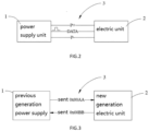
FIG. 2 is a block diagram of a communication and interaction system of the disclosure. -
FIG. 3 is a schematic diagram of a communication between a power supply unit and an electric unit in the embodiment one of the disclosure. -
FIG. 4 is a flow chart of a communication between the power supply unit and the electric unit in the embodiment one of the disclosure. -
FIG. 5 is a schematic diagram of a communication between a power supply unit and an electric unit in the embodiment two of the disclosure. -
FIG. 6 is a flow chart of a communication between the power supply unit and the electric unit in the embodiment two of the disclosure. -
FIG. 7 is a schematic diagram of a communication between a power supply unit and an electric unit in the embodiment three of the disclosure. -
FIG. 8 is a flow chart of a communication between the power supply unit and the electric unit in the embodiment three of the disclosure. -
FIG. 9 is a schematic diagram of a communication between a power supply unit and an electric unit in the embodiment four of the disclosure. -
FIG. 10 is a flow chart of a communication between the power supply unit and the electric unit in the embodiment four of the disclosure. - To make the objects, technical solutions and advantages of the disclosure clearer, the drawings and specific embodiments will be combined to describe the disclosure in detail.
- It should be noted that, to avoid obscuring the disclosure due to unnecessary details, the drawings only show structures and/or processing steps that are closely related to the disclosure, and other details that have little relation to the disclosure are omitted.
- In addition, it should further be noted that the terms 'include', 'including', or any other variation thereof, are intended to cover a non-exclusive inclusion, such that a process, method, article, or device that includes a series of elements not only includes those elements but also includes other elements not expressly listed, or includes inherent elements of the process, method, article, or device.
- Please referring to
FIG. 1 andFIG. 2 ,the disclosure provides a communication and interaction method for communicating and interacting between theelectric unit 2 and thepower supply unit 1. Specifically, the communication and interaction method includes: - providing a
communication module 3 between thepower supply unit 1 and theelectric unit 2; - sending, by the
power supply unit 1, a first identification information to theelectric unit 2 through thecommunication module 3; - parsing, by the
electric unit 2, the first identification information through thecommunication module 3; and - matching and calling, by the
communication module 3, a communication mode and a communication protocol which are simultaneously applicable to thepower supply unit 1 and theelectric unit 2 on the basis of a communication structure of thecommunication module 3, such that the communication between theelectric unit 2 and thepower supply unit 1 is established. - The communication and interaction method further includes replying, by the
electric unit 2, a second identification information to thepower supply unit 1 through thecommunication module 3 according to the first identification information parsed through thecommunication module 3, and parsing the second identification information through the communication module3. - It should be noted that the communication structure in the disclosure refers that the
power supply unit 1, theelectric unit 2, and thecommunication module 3 have a serial communication protocol and a communication mode for interaction and communication. And in the disclosure, the communication mode includes, but not be limited to, the structure and number of the communication lines. - Further, the
power supply unit 1 and theelectric unit 2 are the power supply appliance and the electric appliance which are arranged relatively. In particular, in the field of garden machinery, if thepower supply unit 1 is a battery pack, theelectric unit 2 can be a garden tool powered by the battery pack to work, such as a mower, a snow thrower, a chain saw, or the like. And when thepower supply unit 1 is a charger, theelectric unit 2 may be a rechargeable battery pack or a rechargeable garden tool. Namely, in the disclosure, the specific models of thepower supply unit 1 and theelectric unit 2 in the communication and interaction system 200 can be selected according to actual needs, and is not limited thereto. - In particular, the communication and interaction method of the disclosure is mainly applied to the initial phase of the communication establishment between the
power supply unit 1 and theelectric unit 2. Namely, in the initial phase of the communication establishment, the communication request is initiated by at least one of thepower supply unit 1 and the electric unit 2 (in the disclosure, taking thepower supply unit 1 which initiates the request as an example), the other (in the disclosure, taking theelectric unit 2 as an example) sends the corresponding communication information to reply after receiving the parsed data. Finally thepower supply unit 1 continues to send the next frame of data, and the communication between thepower supply unit 1 and theelectric unit 2 is established. - Further, the
communication module 3 is configured to provide a communication interface between thepower supply unit 1 and theelectric unit 2. And thecommunication module 3 includes a hardware circuit, a connection terminal, and a power supply line and a communication line which are integrated on the hardware circuit. Moreover, a plurality of serial communication protocols and communication modes are integrated on thecommunication module 3, such that thecommunication module 3 can match and call the serial communication protocol and the communication mode which are applicable to thepower supply unit 1 and theelectric unit 2 on the basis of the communication structure of thecommunication module 3 to establish communication between thepower supply unit 1 and theelectric unit 2. - Specifically, the
power supply unit 1 sends the first identification information to theelectric unit 2 through thecommunication module 3, and theelectric unit 2 obtains the first identification information through thecommunication module 3 and transmits the second identification information to thepower supply unit 1. Wherein thecommunication module 3 can also simultaneously or separately parse the first identification information and the second identification information. And in the disclosure the first identification information and the second identification each includes at least two groups of identification bytes. At least one of the two groups of identification bytes carries a serial communication protocol information of the power supply unit and the electric unit. - In one embodiment of the disclosure, the first identification information includes a first identification byte carrying a model information of the
power supply unit 1 and a second identification byte carrying a serial communication protocol information of thepower supply unit 1. And the second identification information includes a third identification byte carrying the model information of theelectric unit 2 and a fourth identification byte carrying a serial communication protocol information of theelectric unit 2. Thus, the information content carried by the first identification information and the second identification information can be simplified, in the mean time, it is convenient for thecommunication module 3 to identify and match the models and the serial communication protocols of thepower supply unit 1 and theelectric unit 2, and the accuracy and stability of the information identification of thecommunication module 3 can be ensured. - Further, the
communication module 3 can also match with the communication mode simultaneously applicable to thepower supply unit 1 and theelectric unit 2 through the first identification information and the second identification information. In the disclosure, the communication mode is influenced by the model of thepower supply unit 1 and theelectric unit 2, and the communication mode at least includes the structure of the communication line of thepower supply unit 1 and theelectric unit 2. - In a preferable embodiment of the disclosure, the
communication module 3 includes a positive electrode (P +) of the power supply, a negative electrode (P-) of the power supply, and a communication line (Data) which are used for connecting thepower supply unit 1 with theelectric unit 2. Wherein, the communication line is arranged with one as an example, in fact, since there may be a difference between model of thepower supply unit 1 and the model of theelectric unit 2, the communication mode between the two may be different, namely, the number of communication lines may be arranged to be different. Therefore, the number of communication lines of thepower supply unit 1 and theelectric unit 2 may be different. When there is a difference in the number of communication lines between thepower supply unit 1 and theelectric unit 2, thecommunication module 3 may call a communication mode that matches thepower supply unit 1 and theelectric unit 2 at the same time, and the hardware circuit and the connection terminal of thecommunication module 3 do not change accordingly. - Preferably, a communication mode for establishing a communication channel between the
power supply unit 1 and theelectric unit 2 includes one or more of UART, 1-Wire, CAN, IIC data bus, and the like. In the disclosure, thecommunication module 3 can select a communication line matched with the serial communication protocol as the communication mode between thepower supply unit 1 and theelectric unit 2 on the basis of parsing and selecting a corresponding serial communication protocol, thereby the communication stability between thepower supply unit 1 and theelectric unit 2 can be ensured. - In the following description, the example is that the first identification information includes a first identification byte carrying a model information of the
power supply unit 1 and a second identification byte carrying a serial communication protocol of thepower supply unit 1, and the second identification information includes a third identification byte carrying a model information of theelectric unit 2 and a fourth identification byte carrying the serial communication protocol of theelectric unit 2. And the communication and interaction method of the disclosure will be described in detail with reference to specific embodiments. - Referring to
FIG.3 andFIG.4 , in the present embodiment, thepower supply unit 1 is a previous generation power supply unit adopting an old serial communication mode, and theelectric unit 2 is a new generation electric unit adopting a new serial communication mode. - Further, the
communication module 3 is integrated in theelectric unit 2 and can receive and parse the first identification information sent by thepower supply unit 1 to assist theelectrical unit 2 in matching the serial communication protocol and the communication mode which are applicable to thepower supply tool 1, without changing the structure of theelectric unit 2 and thecommunication module 3. - In the present embodiment, when starting the
electric unit 2, theelectric unit 2 and thecommunication module 3 are powered on, thepower supply unit 1 is electrically connected to theelectric unit 2 through thecommunication module 3, and thepower supply unit 1 is activated. Then thepower supply unit 1 sends the first identification information 0x00AA, and thecommunication module 3 parses whether the second identification byte carried in the first identification information 0x00AA is 0xAA. If the second identification byte is 0xAA, thecommunication module 3 parses whether the first identification byte carried in the first identification information 0x00AA is 0xCC. And if the second identification byte is not 0xCC, thepower supply unit 1 is determined to be the previous generation power supply unit that use the old serial communication protocol. - Further, the
electric unit 2 replies the second identification information 0x00BB matched with the first identification information 0x00AA through thecommunication module 3 according to the first identification information 0x00AA parsed by thecommunication module 3, and matches with the old serial communication protocol and the communication line conforming to the previous generation power supply unit via thecommunication module 3, to further receive the next frame communication data sent by thepower supply unit 1 to enter the old serial communication phase to complete the communication establishment between theelectric unit 2 and thepower supply unit 1. - Referring to
FIG. 5 andFIG. 6 , in the present embodiment, thepower supply unit 1 is a new generation power supply unit adopting a new serial communication mode, and theelectric unit 2 is the previous generation power unit adopting the old serial communication mode. - Further, the
communication module 3 is integrated into theelectric unit 2 and can receive and parse the first identification information sent by thepower supply unit 1 to assist thepower supply unit 1 in matching with the serial communication protocol and the communication mode which are applicable to theelectric unit 2, without changing the structure of theelectric unit 2 and thecommunication module 3. - In the present embodiment, when starting the
electric unit 2, theelectric unit 2 and thecommunication module 3 are powered on, thepower supply unit 1 is electrically connected to theelectric unit 2 through thecommunication module 3, and thepower supply unit 1 is activated. Then thepower supply unit 1 sends the first identification information 0xCCAA, and thecommunication module 3 parses whether the second identification byte carried in the first identification information 0x00AA is 0xAA. If the second identification byte is 0xAA, thepower supply unit 1 is determined to adopt a new serial communication protocol. - The
electric unit 2 replies the second identification information 0x00BB through thecommunication module 3 and thecommunication module 3 parses the second identification information 0x00BB. And theelectric unit 2 is determined to be a previous generationelectric unit 2 adopting the old serial communication protocol. Furthermore, thecommunication module 3 can also be used for parsing the first identification byte 0xCC and the third identification byte 0x00 to determine thepower supply unit 1 as a new generation power supply unit. Since theelectric unit 2 is the previous generation electric unit and the new serial communication protocol used by thepower supply unit 1 can be downward compatible with the old serial communication protocol used by theelectric unit 2, thecommunication module 3 matches the old serial communication protocol and the communication line conforming to the previous generation electric unit which are applicable to thepower supply unit 1 and theelectric unit 2,and further receives the next frame communication data sent by thepower supply unit 1, then enters the old serial communication phase to complete the communication establishment between theelectric unit 2 and thepower supply unit 1. - Referring to
FIG. 7 andFIG.8 , in the present embodiment, thepower supply unit 1 is a new generation power supply unit adopting a new serial communication mode, and theelectric unit 2 is a new generation electric unit adopting a new serial communication mode. - Further, the
communication module 3 is integrated into theelectric unit 2. Under the condition that the structure of theelectric unit 2 and thecommunication module 3 is not changed, thecommunication module 3 can receive the first identification information sent by thepower supply unit 1 and the second identification information sent by theelectric unit 2, and can communicatively connectpower supply unit 1 with theelectric unit 2. - In particular, in this embodiment, when starting the
electric unit 2, theelectric unit 2 and thecommunication module 3 are powered on, thepower supply unit 1 is electrically connected to theelectric unit 2 through thecommunication module 3, and thepower supply unit 1 is activated. Then thepower supply unit 1 sends the first identification information 0xCCAA via thecommunication module 3, and thecommunication module 3 parses whether the second identification byte carried in the first identification information 0xCCAA is 0xAA. If the second identification byte is 0xAA, thecommunication module 3 parses whether the first identification byte carried in the first identification information 0xCCAA is 0xCC. And if the second identification byte is 0xCC, thepower supply unit 1 is determined to be a new generation power supply unit that use a new serial communication protocol. - Further, the
electric unit 2 determines thepower supply unit 1 as a new generation power supply unit using a new serial communication protocol according to the first identification information 0xCCAA parsed by thecommunication module 3; and replies, by thecommunication module 3, a second identification information 0xDDBB matching with the first identification information 0xCCAA sent by the new generation power supply unit. Thecommunication module 3 can determine both thepower supply unit 1 and theelectric unit 2 as the new tools adopting the new serial communication protocols. At this moment, thecommunication module 3 uses the new serial communication protocol to communicatively connect thepower supply unit 1 with theelectric unit 2 to establish communication between theelectric unit 2 and thepower supply unit 1. - Referring to
FIG.9 andFIG. 10 , in the present embodiment, thepower supply unit 1 is the previous generation power supply unit adopting the old serial communication mode, and theelectric unit 2 is the previous generation electric unit adopting the old serial communication mode. - Further, the
communication module 3 is integrated into theelectric unit 2. Without changing the structure of theelectric unit 2 and thecommunication module 3, thecommunication module 3 can receive the first identification information sent by thepower supply unit 1 and the second identification information sent by theelectric unit 2 to communicatively connect thepower supply unit 1 with theelectric unit 2. - Specifically, in the present embodiment, when starting the
electric unit 2, theelectric unit 2 and thecommunication module 3 are powered on, thepower supply unit 1 is electrically connected to theelectric unit 2 via thecommunication module 3, and thepower supply unit 1 is activated. Then thepower supply unit 1 sends the first identification information 0x00AA via thecommunication module 3, and thecommunication module 3 parses whether the second identification byte carried in the first identification information 0x00AA is 0xAA. If the second identification byte is 0xAA, thecommunication module 3 parses the first identification byte 0x00 to determine thepower supply unit 1 to be the previous generation power supply unit that uses the old serial communication protocol. - The
electric unit 2 replies the second identification information 0x00BB matching with the first identification information 0x00AA via thecommunication module 3 according to the first identification information 0x00AA parsed by thecommunication module 3, to determine theelectric unit 2 as the previous generation electric unit adopting the old serial communication protocol. Since the new serial communication protocol used by thepower supply unit 1 can be downward compatible with the old serial communication protocol used by theelectric unit 2, thecommunication module 3 matches the old serial communication protocol and the communication line conforming to the previous generation electric unit which are applicable to thepower supply unit 1 and theelectric unit 2, and further receives the next frame communication data sent by thepower supply unit 1, then enters the old serial communication phase to complete the communication establishment between theelectric unit 2 and thepower supply unit 1. - It should be noted that, in an embodiment of the disclosure, it is taken as an example that only two sets of identifying bytes are present in the first identification information and the second identification information, the first identification byte carries model information for determining the
power supply unit 1 or theelectric unit 2 and the second identification byte carries a serial communication protocol and corresponding communication mode information for determining thepower supply unit 1 and theelectric unit 2. In other embodiments of the disclosure, the first identification information and the second identification information may each include a plurality of different sets of identification bytes, and each byte may carry different identification information. Namely, the number of identification bytes contained in the first identification information and the second identification information in the disclosure and the information carried by the identification byte may be selected according to actual needs. The contents of the embodiments are exemplary only, and should not be limited herein. - Referring to
FIG.2 , the disclosure also provides a communication and interaction system. The communication and interaction system 200 includes apower supply unit 1, anelectric unit 2, and acommunication module 3 for communicatively connecting thepower supply unit 1 with theelectric unit 2. And in the disclosure, thecommunication module 3 includes a hardware circuit, a connection terminal, and a power supply line and a communication line which are integrated on the hardware circuit. And the communication module can match and call the serial communication protocol applicable to thepower supply unit 1 and theelectric unit 2 on the basis of the communication structure of the communication module itself. Such that the communication between theelectric unit 2 and thepower supply unit 1 is established. The communication and interaction system of the disclosure can also be used to perform the aforementioned communication and interaction method. - It should be noted that, in the disclosure, the
power supply unit 1 and theelectric unit 2 are a power supply appliance and an electric appliance which are arranged relatively. Specifically, in the field of garden machinery, if thepower supply unit 1 is a battery pack, theelectric unit 2 can be a garden tool powered by the battery pack to work, such as a mower, a snow thrower, a chain saw, and the like. When thepower supply unit 1 is a charger, theelectric unit 2 may be a rechargeable battery pack or a rechargeable garden tool. Namely, in the disclosure, the specific model of thepower supply unit 1 and theelectric unit 2 in the communication and interaction system 200 may be selected according to actual needs, but should not be limited herein. - Further, in the embodiment of the disclosure, the
communication module 3 is arranged on theelectric unit 2 as an example. In fact, in other embodiments of the disclosure, thecommunication module 3 may also be provided on thepower supply unit 1 or present as a separate component. Namely, the specific position and form of thecommunication module 3 in the disclosure may be selected according to actual needs, but should not be limited herein. - In summary, the communication and interaction method of the disclosure determines the serial communication protocol and communication mode of the
power supply unit 1 and theelectric unit 2 through the communication module 3.Without changing the structures of thepower supply unit 1, theelectric unit 2, and thecommunication module 3, the communication connection between thepower supply unit 1 and theelectric unit 2 using two different serial communication protocols and communication modes is realized. Meanwhile, the communication and interaction system using the communication and interaction method can ensure the communication compatibility between thepower supply unit 1 and theelectric unit 2 of different generations, and can effectively improve the working time and the application range of thepower supply unit 1 and theelectric unit 2. - The above embodiments is only used to illustrate the technical proposal of the disclosure, but not limited thereto. Although the disclosure has been described in detail with reference to preferable embodiments, it will be understood by those skilled in the field, and can be modified or replaced with equivalents as long as they fall within the scope of the appended claims.
Claims (8)
- A communication and interaction method for communicating and interacting between an electric unit (2) and a power supply unit (1), comprising:providing a communication module (3) between the power supply unit (1) and the electric unit (2);sending, by the power supply unit (1), a first identification information to the electric unit (2) through the communication module (3);parsing, by the electric unit (2), the first identification information through the communication module (3); characterized byreplying, by the electric unit (2), a second identification information to the power supply unit (1) through the communication module (3) according to the first identification information parsed through the communication module (3);parsing the second identification information through the communication module (3); andmatching, by the communication module (3), a serial communication protocol and a communication mode which are applicable to the power supply unit (1) and the electric unit (2) simultaneously through the first identification information and the second identification information and the communication mode at least comprises a structure of a communication line which is capable of being communicatively connected with the power supply unit (1) and the electric unit (2), such that communication between the electric unit (2) and the power supply unit (1) is established.
- The communication and interaction method of claim 1, wherein
the first identification information and the second identification information each comprise at least two groups of identification bytes, and at least one of the two groups of identification bytes carries communication protocol information for the power supply unit (1) and the electric unit (2). - The communication and interaction method according to any one of claims 1 to 2, wherein
the communication module (3) comprises a hardware circuit, a connection terminal, and a power supply line and a communication line which are integrated on the hardware circuit; and the communication line comprises one or more of UART, 1-WIRE, CAN, and IIC. - The communication and interaction method according to any one of claims 1 to 3, whereinthe first identification information comprisesa first identification byte, carrying a model information of the power supply unit (1), anda second identification byte, carrying a serial communication protocol of the power supply unit (1); andthe second identification information comprisesa third identification byte, carrying a model information of the electric unit (2), anda fourth identification byte, carrying a serial communication protocol of the electric unit (2).
- The communication and interaction method of claim 4, wherein
when the communication module (3) parses the first identification information sent through the power supply unit (1), and determines the serial communication protocol adopted by the power supply unit (1) as an old serial communication protocol according to the first identification byte and the second identification byte, the electric unit (2) replies to the power supply unit(1) with the second identification information matched with the first identification information through the communication module (3) according to the first identification information parsed by the communication module (3), and the communication line corresponding to the old serial communication protocol on the communication module (3) uses the old serial communication protocol to establish communication between the electric unit(2) and the power supply unit (1). - The communication and interaction method of claim 4, wherein
the communication module (3) parses the first identification information sent through the power supply unit (1), and determines the serial communication protocol adopted by the power supply unit (1) as a new serial communication protocol according to the second identification byte, then the electric unit (2) replies the second identification information to the power supply unit (1) through the communication module (3), when the communication module (3) determines the serial communication protocol adopted by the electric unit (2) as an old serial communication protocol according to the second identification information, the power supply unit (1) matches the old serial communication protocol and the communication line corresponding to the old serial communication protocol which are applicable to the power supply unit (1) and the electric unit (2), such that communication between the electric unit (2) and the power supply unit (1) is established. - The communication and interaction method of claim 4, wherein
when the communication module (3) parses the first identification information sent by the power supply unit (1), and determines the serial communication protocol adopted by the power supply unit (1) as an old serial communication protocol or a new serial communication mode according to the first identification byte and the second identification byte, the electric unit (2) replies to the power supply unit (1) with the second identification information through the communication module (3) according to the first identification information parsed through the communication module (3), then the communication module (3) determines that the electric unit (2) and the power supply unit (1) adopt a same serial communication protocol according to the second identification information, and communication between the electric unit (2) and the power supply unit (1) is established via a communication line corresponding to the serial communication protocol adopted by the power supply unit (1). - A communication and interaction system, comprising:a power supply unit (1),an electric unit (2), anda communication module (3) for communicatively connecting the power supply unit (1) and the electric unit (2); the communication module (3) comprising:a hardware circuit,a connection terminal,a power supply line, anda communication line, the power supply line and the communication line being integrated on the hardware circuit; wherein the communication and interaction system is configured to perform the method according to any one of claims 1 to 7.
Applications Claiming Priority (1)
| Application Number | Priority Date | Filing Date | Title |
|---|---|---|---|
| CN202011139062.2A CN112291219B (en) | 2020-10-22 | 2020-10-22 | Communication interaction method and system |
Publications (3)
| Publication Number | Publication Date |
|---|---|
| EP3989386A1 EP3989386A1 (en) | 2022-04-27 |
| EP3989386B1 true EP3989386B1 (en) | 2024-07-17 |
| EP3989386C0 EP3989386C0 (en) | 2024-07-17 |
Family
ID=74423617
Family Applications (1)
| Application Number | Title | Priority Date | Filing Date |
|---|---|---|---|
| EP21203933.3A Active EP3989386B1 (en) | 2020-10-22 | 2021-10-21 | Communication and interaction method and system |
Country Status (4)
| Country | Link |
|---|---|
| US (1) | US11996905B2 (en) |
| EP (1) | EP3989386B1 (en) |
| CN (2) | CN112291219B (en) |
| AU (1) | AU2021254663A1 (en) |
Families Citing this family (4)
| Publication number | Priority date | Publication date | Assignee | Title |
|---|---|---|---|---|
| US8727197B2 (en) | 2007-03-15 | 2014-05-20 | Ethicon Endo-Surgery, Inc. | Staple cartridge cavity configuration with cooperative surgical staple |
| DK3223013T3 (en) | 2009-07-02 | 2019-04-15 | Sloan Kettering Inst Cancer Res | FLUORESCING SILICA-BASED NANOPARTICLES |
| CN111682615A (en) * | 2020-06-18 | 2020-09-18 | 格力博(江苏)股份有限公司 | Charging control circuit, charging device and charging system |
| CN121180049A (en) * | 2025-11-17 | 2025-12-23 | 唐泽制动器(天津)有限公司 | A method and system for charging electric vehicles based on multiple communication methods |
Citations (1)
| Publication number | Priority date | Publication date | Assignee | Title |
|---|---|---|---|---|
| US20130214737A1 (en) * | 2012-02-20 | 2013-08-22 | Eaton Corporation | Data transmission device and method between charger and electric vehicle |
Family Cites Families (17)
| Publication number | Priority date | Publication date | Assignee | Title |
|---|---|---|---|---|
| US20100070659A1 (en) * | 2008-09-17 | 2010-03-18 | Kenneth Ma | Method and system for operating and/or charging a battery powered usb device based on a usb port type |
| CN201681422U (en) * | 2010-05-25 | 2010-12-22 | 李元熙 | Equipment power-extracting management system based on RFID and CAN bus technology |
| US8954762B2 (en) * | 2010-06-08 | 2015-02-10 | International Business Machines Corporation | Peer to peer power management |
| US20130076299A1 (en) * | 2011-09-23 | 2013-03-28 | Wu Chin Chao | Charging device capable of automatically distributing charging current |
| KR101813125B1 (en) * | 2011-11-18 | 2017-12-29 | 삼성전자주식회사 | Wireless power transmission system, method for power control of in wireless power transmission system using detecting parameter |
| US9240700B2 (en) * | 2012-09-07 | 2016-01-19 | Apple Inc. | Cascading power for accessories |
| CN104303388B (en) * | 2013-03-29 | 2018-01-05 | 松下知识产权经营株式会社 | Battery pack, electric equipment, communication control method |
| KR101437375B1 (en) * | 2013-09-26 | 2014-11-04 | 주식회사 피엠그로우 | Apparatus and method for changing charge protocol of electric vehicle |
| CN206217652U (en) * | 2016-10-10 | 2017-06-06 | 宝沃汽车(中国)有限公司 | A kind of electric motorcar charging station and charging system of electric powercar |
| CN106740196B (en) * | 2016-12-12 | 2019-08-09 | 国网北京市电力公司 | Charging method and device for DC charging equipment |
| DE102017204727A1 (en) * | 2017-03-21 | 2018-09-27 | Robert Bosch Gmbh | A method for establishing a communication link, vehicle communication device and charging station communication device |
| CN107425998B (en) * | 2017-04-13 | 2020-03-20 | 杭州申昊科技股份有限公司 | Communication link guarantee method based on industrial WIFI |
| CN109660483A (en) * | 2017-10-10 | 2019-04-19 | 深圳市美好创亿医疗科技有限公司 | Embedded hardware communication protocol and communication system |
| CN110460557B (en) * | 2018-05-07 | 2021-02-19 | 北汽福田汽车股份有限公司 | Charging management method and device for electric vehicle, battery management system and electric vehicle |
| CN108833436B (en) * | 2018-07-03 | 2021-07-16 | 一重集团(黑龙江)专项装备科技有限公司 | Communication control method for realizing equipment communication interconnection |
| CN110473307B (en) * | 2019-07-02 | 2024-05-31 | 福建星云电子股份有限公司 | Intelligent battery pairing repair method and system |
| CN110816359A (en) * | 2019-11-20 | 2020-02-21 | 上海度普新能源科技有限公司 | Charging control method and device, battery management system and electric vehicle |
-
2020
- 2020-10-22 CN CN202011139062.2A patent/CN112291219B/en active Active
- 2020-10-22 CN CN202310566510.4A patent/CN116527795B/en active Active
-
2021
- 2021-10-18 US US17/504,459 patent/US11996905B2/en active Active
- 2021-10-21 EP EP21203933.3A patent/EP3989386B1/en active Active
- 2021-10-22 AU AU2021254663A patent/AU2021254663A1/en active Pending
Patent Citations (1)
| Publication number | Priority date | Publication date | Assignee | Title |
|---|---|---|---|---|
| US20130214737A1 (en) * | 2012-02-20 | 2013-08-22 | Eaton Corporation | Data transmission device and method between charger and electric vehicle |
Also Published As
| Publication number | Publication date |
|---|---|
| EP3989386A1 (en) | 2022-04-27 |
| AU2021254663A1 (en) | 2022-05-12 |
| CN112291219A (en) | 2021-01-29 |
| CN116527795A (en) | 2023-08-01 |
| CN116527795B (en) | 2025-10-24 |
| CN112291219B (en) | 2023-06-13 |
| EP3989386C0 (en) | 2024-07-17 |
| US11996905B2 (en) | 2024-05-28 |
| US20220131570A1 (en) | 2022-04-28 |
Similar Documents
| Publication | Publication Date | Title |
|---|---|---|
| EP3989386B1 (en) | Communication and interaction method and system | |
| EP2892214B1 (en) | Mobile terminal, master data communication device, and mobile terminal charging system and method | |
| CN107005062B (en) | Charging method, mobile terminal and charging device | |
| CN112776649B (en) | Charging method for electric vehicle, charging pile, battery management system and medium | |
| CN105429245A (en) | Charging control method and charging control device | |
| CN110492575B (en) | Quick charging system and method for handheld device and handheld device | |
| CN109618318A (en) | A kind of matching method and TWS earphone of TWS earphone | |
| US9705663B2 (en) | Communication system having synchronized units and synchronization method for units | |
| CN107516919B (en) | A charging method and charger | |
| EP2755109B1 (en) | Charging an electrical device via a data interface | |
| CN110166994A (en) | A kind of data time sharing transmissions mutually use method, system, mobile terminal and storage medium | |
| CN109950433B (en) | Communication method suitable for battery pack and battery pack | |
| CN113212225B (en) | Vehicle charging method and device and charger | |
| CN205239183U (en) | Charging cable | |
| CN110226257B (en) | Method and system for managing battery pack | |
| CN216530587U (en) | Power supply connector for supplying power to master equipment and slave equipment | |
| US11325499B2 (en) | Multi-battery system for an electric vehicle | |
| CN211296223U (en) | Power supply adapter | |
| CN112259811A (en) | Simple battery management framework and method | |
| CN112653213A (en) | Charging control method and device | |
| CN208571630U (en) | A kind of multifunctional charger | |
| CN105644382B (en) | Charging cable | |
| CN218482322U (en) | Battery pack based on total positive and total negative communication and communication equipment | |
| CN210348466U (en) | Battery management system firmware off-line upgrading device and electronic product | |
| CN206517545U (en) | Multiple signal acquisition converters |
Legal Events
| Date | Code | Title | Description |
|---|---|---|---|
| PUAI | Public reference made under article 153(3) epc to a published international application that has entered the european phase |
Free format text: ORIGINAL CODE: 0009012 |
|
| STAA | Information on the status of an ep patent application or granted ep patent |
Free format text: STATUS: THE APPLICATION HAS BEEN PUBLISHED |
|
| AK | Designated contracting states |
Kind code of ref document: A1 Designated state(s): AL AT BE BG CH CY CZ DE DK EE ES FI FR GB GR HR HU IE IS IT LI LT LU LV MC MK MT NL NO PL PT RO RS SE SI SK SM TR |
|
| STAA | Information on the status of an ep patent application or granted ep patent |
Free format text: STATUS: REQUEST FOR EXAMINATION WAS MADE |
|
| 17P | Request for examination filed |
Effective date: 20221010 |
|
| RBV | Designated contracting states (corrected) |
Designated state(s): AL AT BE BG CH CY CZ DE DK EE ES FI FR GB GR HR HU IE IS IT LI LT LU LV MC MK MT NL NO PL PT RO RS SE SI SK SM TR |
|
| GRAP | Despatch of communication of intention to grant a patent |
Free format text: ORIGINAL CODE: EPIDOSNIGR1 |
|
| STAA | Information on the status of an ep patent application or granted ep patent |
Free format text: STATUS: GRANT OF PATENT IS INTENDED |
|
| RIC1 | Information provided on ipc code assigned before grant |
Ipc: H02J 7/00 20060101AFI20240318BHEP |
|
| INTG | Intention to grant announced |
Effective date: 20240417 |
|
| GRAS | Grant fee paid |
Free format text: ORIGINAL CODE: EPIDOSNIGR3 |
|
| GRAA | (expected) grant |
Free format text: ORIGINAL CODE: 0009210 |
|
| STAA | Information on the status of an ep patent application or granted ep patent |
Free format text: STATUS: THE PATENT HAS BEEN GRANTED |
|
| AK | Designated contracting states |
Kind code of ref document: B1 Designated state(s): AL AT BE BG CH CY CZ DE DK EE ES FI FR GB GR HR HU IE IS IT LI LT LU LV MC MK MT NL NO PL PT RO RS SE SI SK SM TR |
|
| REG | Reference to a national code |
Ref country code: CH Ref legal event code: EP |
|
| REG | Reference to a national code |
Ref country code: DE Ref legal event code: R096 Ref document number: 602021015746 Country of ref document: DE |
|
| REG | Reference to a national code |
Ref country code: IE Ref legal event code: FG4D |
|
| U01 | Request for unitary effect filed |
Effective date: 20240717 |
|
| U07 | Unitary effect registered |
Designated state(s): AT BE BG DE DK EE FI FR IT LT LU LV MT NL PT SE SI Effective date: 20240725 |
|
| U20 | Renewal fee for the european patent with unitary effect paid |
Year of fee payment: 4 Effective date: 20241028 |
|
| PG25 | Lapsed in a contracting state [announced via postgrant information from national office to epo] |
Ref country code: NO Free format text: LAPSE BECAUSE OF FAILURE TO SUBMIT A TRANSLATION OF THE DESCRIPTION OR TO PAY THE FEE WITHIN THE PRESCRIBED TIME-LIMIT Effective date: 20241017 |
|
| PG25 | Lapsed in a contracting state [announced via postgrant information from national office to epo] |
Ref country code: GR Free format text: LAPSE BECAUSE OF FAILURE TO SUBMIT A TRANSLATION OF THE DESCRIPTION OR TO PAY THE FEE WITHIN THE PRESCRIBED TIME-LIMIT Effective date: 20241018 Ref country code: PL Free format text: LAPSE BECAUSE OF FAILURE TO SUBMIT A TRANSLATION OF THE DESCRIPTION OR TO PAY THE FEE WITHIN THE PRESCRIBED TIME-LIMIT Effective date: 20240717 |
|
| PG25 | Lapsed in a contracting state [announced via postgrant information from national office to epo] |
Ref country code: IS Free format text: LAPSE BECAUSE OF FAILURE TO SUBMIT A TRANSLATION OF THE DESCRIPTION OR TO PAY THE FEE WITHIN THE PRESCRIBED TIME-LIMIT Effective date: 20241117 |
|
| PG25 | Lapsed in a contracting state [announced via postgrant information from national office to epo] |
Ref country code: HR Free format text: LAPSE BECAUSE OF FAILURE TO SUBMIT A TRANSLATION OF THE DESCRIPTION OR TO PAY THE FEE WITHIN THE PRESCRIBED TIME-LIMIT Effective date: 20240717 |
|
| PG25 | Lapsed in a contracting state [announced via postgrant information from national office to epo] |
Ref country code: ES Free format text: LAPSE BECAUSE OF FAILURE TO SUBMIT A TRANSLATION OF THE DESCRIPTION OR TO PAY THE FEE WITHIN THE PRESCRIBED TIME-LIMIT Effective date: 20240717 Ref country code: RS Free format text: LAPSE BECAUSE OF FAILURE TO SUBMIT A TRANSLATION OF THE DESCRIPTION OR TO PAY THE FEE WITHIN THE PRESCRIBED TIME-LIMIT Effective date: 20241017 |
|
| PG25 | Lapsed in a contracting state [announced via postgrant information from national office to epo] |
Ref country code: RS Free format text: LAPSE BECAUSE OF FAILURE TO SUBMIT A TRANSLATION OF THE DESCRIPTION OR TO PAY THE FEE WITHIN THE PRESCRIBED TIME-LIMIT Effective date: 20241017 Ref country code: PL Free format text: LAPSE BECAUSE OF FAILURE TO SUBMIT A TRANSLATION OF THE DESCRIPTION OR TO PAY THE FEE WITHIN THE PRESCRIBED TIME-LIMIT Effective date: 20240717 Ref country code: NO Free format text: LAPSE BECAUSE OF FAILURE TO SUBMIT A TRANSLATION OF THE DESCRIPTION OR TO PAY THE FEE WITHIN THE PRESCRIBED TIME-LIMIT Effective date: 20241017 Ref country code: IS Free format text: LAPSE BECAUSE OF FAILURE TO SUBMIT A TRANSLATION OF THE DESCRIPTION OR TO PAY THE FEE WITHIN THE PRESCRIBED TIME-LIMIT Effective date: 20241117 Ref country code: HR Free format text: LAPSE BECAUSE OF FAILURE TO SUBMIT A TRANSLATION OF THE DESCRIPTION OR TO PAY THE FEE WITHIN THE PRESCRIBED TIME-LIMIT Effective date: 20240717 Ref country code: GR Free format text: LAPSE BECAUSE OF FAILURE TO SUBMIT A TRANSLATION OF THE DESCRIPTION OR TO PAY THE FEE WITHIN THE PRESCRIBED TIME-LIMIT Effective date: 20241018 Ref country code: ES Free format text: LAPSE BECAUSE OF FAILURE TO SUBMIT A TRANSLATION OF THE DESCRIPTION OR TO PAY THE FEE WITHIN THE PRESCRIBED TIME-LIMIT Effective date: 20240717 |
|
| PG25 | Lapsed in a contracting state [announced via postgrant information from national office to epo] |
Ref country code: SM Free format text: LAPSE BECAUSE OF FAILURE TO SUBMIT A TRANSLATION OF THE DESCRIPTION OR TO PAY THE FEE WITHIN THE PRESCRIBED TIME-LIMIT Effective date: 20240717 |
|
| PG25 | Lapsed in a contracting state [announced via postgrant information from national office to epo] |
Ref country code: CZ Free format text: LAPSE BECAUSE OF FAILURE TO SUBMIT A TRANSLATION OF THE DESCRIPTION OR TO PAY THE FEE WITHIN THE PRESCRIBED TIME-LIMIT Effective date: 20240717 |
|
| PG25 | Lapsed in a contracting state [announced via postgrant information from national office to epo] |
Ref country code: SK Free format text: LAPSE BECAUSE OF FAILURE TO SUBMIT A TRANSLATION OF THE DESCRIPTION OR TO PAY THE FEE WITHIN THE PRESCRIBED TIME-LIMIT Effective date: 20240717 |
|
| PLBE | No opposition filed within time limit |
Free format text: ORIGINAL CODE: 0009261 |
|
| STAA | Information on the status of an ep patent application or granted ep patent |
Free format text: STATUS: NO OPPOSITION FILED WITHIN TIME LIMIT |
|
| REG | Reference to a national code |
Ref country code: CH Ref legal event code: PL |
|
| 26N | No opposition filed |
Effective date: 20250422 |
|
| PG25 | Lapsed in a contracting state [announced via postgrant information from national office to epo] |
Ref country code: MC Free format text: LAPSE BECAUSE OF FAILURE TO SUBMIT A TRANSLATION OF THE DESCRIPTION OR TO PAY THE FEE WITHIN THE PRESCRIBED TIME-LIMIT Effective date: 20240717 |
|
| PG25 | Lapsed in a contracting state [announced via postgrant information from national office to epo] |
Ref country code: CH Free format text: LAPSE BECAUSE OF NON-PAYMENT OF DUE FEES Effective date: 20241031 |
|
| PG25 | Lapsed in a contracting state [announced via postgrant information from national office to epo] |
Ref country code: IE Free format text: LAPSE BECAUSE OF NON-PAYMENT OF DUE FEES Effective date: 20241021 |
|
| PG25 | Lapsed in a contracting state [announced via postgrant information from national office to epo] |
Ref country code: RO Free format text: LAPSE BECAUSE OF FAILURE TO SUBMIT A TRANSLATION OF THE DESCRIPTION OR TO PAY THE FEE WITHIN THE PRESCRIBED TIME-LIMIT Effective date: 20240717 |
|
| U20 | Renewal fee for the european patent with unitary effect paid |
Year of fee payment: 5 Effective date: 20251027 |
|
| PGFP | Annual fee paid to national office [announced via postgrant information from national office to epo] |
Ref country code: GB Payment date: 20251024 Year of fee payment: 5 |
|
| PG25 | Lapsed in a contracting state [announced via postgrant information from national office to epo] |
Ref country code: CY Free format text: LAPSE BECAUSE OF FAILURE TO SUBMIT A TRANSLATION OF THE DESCRIPTION OR TO PAY THE FEE WITHIN THE PRESCRIBED TIME-LIMIT; INVALID AB INITIO Effective date: 20211021 |
|
| PG25 | Lapsed in a contracting state [announced via postgrant information from national office to epo] |
Ref country code: HU Free format text: LAPSE BECAUSE OF FAILURE TO SUBMIT A TRANSLATION OF THE DESCRIPTION OR TO PAY THE FEE WITHIN THE PRESCRIBED TIME-LIMIT; INVALID AB INITIO Effective date: 20211021 |