EP3989352A1 - Secondary battery, battery module, and device using battery as power source - Google Patents
Secondary battery, battery module, and device using battery as power source Download PDFInfo
- Publication number
- EP3989352A1 EP3989352A1 EP20913277.8A EP20913277A EP3989352A1 EP 3989352 A1 EP3989352 A1 EP 3989352A1 EP 20913277 A EP20913277 A EP 20913277A EP 3989352 A1 EP3989352 A1 EP 3989352A1
- Authority
- EP
- European Patent Office
- Prior art keywords
- insulator
- secondary battery
- main body
- connection portion
- overlayer
- Prior art date
- Legal status (The legal status is an assumption and is not a legal conclusion. Google has not performed a legal analysis and makes no representation as to the accuracy of the status listed.)
- Granted
Links
Images






Classifications
-
- H—ELECTRICITY
- H01—ELECTRIC ELEMENTS
- H01M—PROCESSES OR MEANS, e.g. BATTERIES, FOR THE DIRECT CONVERSION OF CHEMICAL ENERGY INTO ELECTRICAL ENERGY
- H01M50/00—Constructional details or processes of manufacture of the non-active parts of electrochemical cells other than fuel cells, e.g. hybrid cells
- H01M50/50—Current conducting connections for cells or batteries
- H01M50/531—Electrode connections inside a battery casing
- H01M50/533—Electrode connections inside a battery casing characterised by the shape of the leads or tabs
-
- H—ELECTRICITY
- H01—ELECTRIC ELEMENTS
- H01M—PROCESSES OR MEANS, e.g. BATTERIES, FOR THE DIRECT CONVERSION OF CHEMICAL ENERGY INTO ELECTRICAL ENERGY
- H01M10/00—Secondary cells; Manufacture thereof
- H01M10/04—Construction or manufacture in general
- H01M10/0431—Cells with wound or folded electrodes
-
- H—ELECTRICITY
- H01—ELECTRIC ELEMENTS
- H01M—PROCESSES OR MEANS, e.g. BATTERIES, FOR THE DIRECT CONVERSION OF CHEMICAL ENERGY INTO ELECTRICAL ENERGY
- H01M10/00—Secondary cells; Manufacture thereof
- H01M10/05—Accumulators with non-aqueous electrolyte
- H01M10/052—Li-accumulators
- H01M10/0525—Rocking-chair batteries, i.e. batteries with lithium insertion or intercalation in both electrodes; Lithium-ion batteries
-
- H—ELECTRICITY
- H01—ELECTRIC ELEMENTS
- H01M—PROCESSES OR MEANS, e.g. BATTERIES, FOR THE DIRECT CONVERSION OF CHEMICAL ENERGY INTO ELECTRICAL ENERGY
- H01M10/00—Secondary cells; Manufacture thereof
- H01M10/05—Accumulators with non-aqueous electrolyte
- H01M10/058—Construction or manufacture
- H01M10/0587—Construction or manufacture of accumulators having only wound construction elements, i.e. wound positive electrodes, wound negative electrodes and wound separators
-
- H—ELECTRICITY
- H01—ELECTRIC ELEMENTS
- H01M—PROCESSES OR MEANS, e.g. BATTERIES, FOR THE DIRECT CONVERSION OF CHEMICAL ENERGY INTO ELECTRICAL ENERGY
- H01M50/00—Constructional details or processes of manufacture of the non-active parts of electrochemical cells other than fuel cells, e.g. hybrid cells
- H01M50/10—Primary casings; Jackets or wrappings
- H01M50/147—Lids or covers
-
- H—ELECTRICITY
- H01—ELECTRIC ELEMENTS
- H01M—PROCESSES OR MEANS, e.g. BATTERIES, FOR THE DIRECT CONVERSION OF CHEMICAL ENERGY INTO ELECTRICAL ENERGY
- H01M50/00—Constructional details or processes of manufacture of the non-active parts of electrochemical cells other than fuel cells, e.g. hybrid cells
- H01M50/10—Primary casings; Jackets or wrappings
- H01M50/147—Lids or covers
- H01M50/148—Lids or covers characterised by their shape
- H01M50/15—Lids or covers characterised by their shape for prismatic or rectangular cells
-
- H—ELECTRICITY
- H01—ELECTRIC ELEMENTS
- H01M—PROCESSES OR MEANS, e.g. BATTERIES, FOR THE DIRECT CONVERSION OF CHEMICAL ENERGY INTO ELECTRICAL ENERGY
- H01M50/00—Constructional details or processes of manufacture of the non-active parts of electrochemical cells other than fuel cells, e.g. hybrid cells
- H01M50/10—Primary casings; Jackets or wrappings
- H01M50/172—Arrangements of electric connectors penetrating the casing
-
- H—ELECTRICITY
- H01—ELECTRIC ELEMENTS
- H01M—PROCESSES OR MEANS, e.g. BATTERIES, FOR THE DIRECT CONVERSION OF CHEMICAL ENERGY INTO ELECTRICAL ENERGY
- H01M50/00—Constructional details or processes of manufacture of the non-active parts of electrochemical cells other than fuel cells, e.g. hybrid cells
- H01M50/20—Mountings; Secondary casings or frames; Racks, modules or packs; Suspension devices; Shock absorbers; Transport or carrying devices; Holders
- H01M50/204—Racks, modules or packs for multiple batteries or multiple cells
- H01M50/207—Racks, modules or packs for multiple batteries or multiple cells characterised by their shape
- H01M50/209—Racks, modules or packs for multiple batteries or multiple cells characterised by their shape adapted for prismatic or rectangular cells
-
- H—ELECTRICITY
- H01—ELECTRIC ELEMENTS
- H01M—PROCESSES OR MEANS, e.g. BATTERIES, FOR THE DIRECT CONVERSION OF CHEMICAL ENERGY INTO ELECTRICAL ENERGY
- H01M50/00—Constructional details or processes of manufacture of the non-active parts of electrochemical cells other than fuel cells, e.g. hybrid cells
- H01M50/50—Current conducting connections for cells or batteries
- H01M50/528—Fixed electrical connections, i.e. not intended for disconnection
-
- H—ELECTRICITY
- H01—ELECTRIC ELEMENTS
- H01M—PROCESSES OR MEANS, e.g. BATTERIES, FOR THE DIRECT CONVERSION OF CHEMICAL ENERGY INTO ELECTRICAL ENERGY
- H01M50/00—Constructional details or processes of manufacture of the non-active parts of electrochemical cells other than fuel cells, e.g. hybrid cells
- H01M50/50—Current conducting connections for cells or batteries
- H01M50/531—Electrode connections inside a battery casing
- H01M50/534—Electrode connections inside a battery casing characterised by the material of the leads or tabs
-
- H—ELECTRICITY
- H01—ELECTRIC ELEMENTS
- H01M—PROCESSES OR MEANS, e.g. BATTERIES, FOR THE DIRECT CONVERSION OF CHEMICAL ENERGY INTO ELECTRICAL ENERGY
- H01M50/00—Constructional details or processes of manufacture of the non-active parts of electrochemical cells other than fuel cells, e.g. hybrid cells
- H01M50/50—Current conducting connections for cells or batteries
- H01M50/531—Electrode connections inside a battery casing
- H01M50/536—Electrode connections inside a battery casing characterised by the method of fixing the leads to the electrodes, e.g. by welding
-
- H—ELECTRICITY
- H01—ELECTRIC ELEMENTS
- H01M—PROCESSES OR MEANS, e.g. BATTERIES, FOR THE DIRECT CONVERSION OF CHEMICAL ENERGY INTO ELECTRICAL ENERGY
- H01M50/00—Constructional details or processes of manufacture of the non-active parts of electrochemical cells other than fuel cells, e.g. hybrid cells
- H01M50/50—Current conducting connections for cells or batteries
- H01M50/531—Electrode connections inside a battery casing
- H01M50/538—Connection of several leads or tabs of wound or folded electrode stacks
-
- H—ELECTRICITY
- H01—ELECTRIC ELEMENTS
- H01M—PROCESSES OR MEANS, e.g. BATTERIES, FOR THE DIRECT CONVERSION OF CHEMICAL ENERGY INTO ELECTRICAL ENERGY
- H01M50/00—Constructional details or processes of manufacture of the non-active parts of electrochemical cells other than fuel cells, e.g. hybrid cells
- H01M50/50—Current conducting connections for cells or batteries
- H01M50/572—Means for preventing undesired use or discharge
- H01M50/584—Means for preventing undesired use or discharge for preventing incorrect connections inside or outside the batteries
- H01M50/59—Means for preventing undesired use or discharge for preventing incorrect connections inside or outside the batteries characterised by the protection means
- H01M50/593—Spacers; Insulating plates
-
- H—ELECTRICITY
- H01—ELECTRIC ELEMENTS
- H01M—PROCESSES OR MEANS, e.g. BATTERIES, FOR THE DIRECT CONVERSION OF CHEMICAL ENERGY INTO ELECTRICAL ENERGY
- H01M2220/00—Batteries for particular applications
- H01M2220/20—Batteries in motive systems, e.g. vehicle, ship, plane
-
- Y—GENERAL TAGGING OF NEW TECHNOLOGICAL DEVELOPMENTS; GENERAL TAGGING OF CROSS-SECTIONAL TECHNOLOGIES SPANNING OVER SEVERAL SECTIONS OF THE IPC; TECHNICAL SUBJECTS COVERED BY FORMER USPC CROSS-REFERENCE ART COLLECTIONS [XRACs] AND DIGESTS
- Y02—TECHNOLOGIES OR APPLICATIONS FOR MITIGATION OR ADAPTATION AGAINST CLIMATE CHANGE
- Y02E—REDUCTION OF GREENHOUSE GAS [GHG] EMISSIONS, RELATED TO ENERGY GENERATION, TRANSMISSION OR DISTRIBUTION
- Y02E60/00—Enabling technologies; Technologies with a potential or indirect contribution to GHG emissions mitigation
- Y02E60/10—Energy storage using batteries
Definitions
- Embodiments of this application relate to the field of batteries, and in particular, to a secondary battery, a battery module, and a device using a battery as a power supply.
- a secondary battery such as a lithium-ion battery is widely used in electronic devices such as a mobile phone and a notebook computer by virtue of a high energy density and environmental friendliness.
- electronic devices such as a mobile phone and a notebook computer by virtue of a high energy density and environmental friendliness.
- the application of lithium-ion batteries has been rapidly expanded to hybrid electric vehicles, ships, and energy storage systems.
- a secondary battery mainly includes a housing and an electrode assembly disposed in the housing.
- the housing contains electrode terminals, and the electrode assembly contains tabs.
- the tabs are electrically connected to the electrode terminals.
- the tabs need to be bent to occupy a smaller space.
- an objective of this application is to provide a secondary battery, a battery module, and a device using a battery as a power supply to make tabs occupy a smaller space and reduce the risk of rupturing the tabs.
- the secondary battery includes: a cap plate; electrode terminals, disposed on the cap plate; an electrode assembly, including a main body and tabs extending from the main body, where each of the tabs includes a connection portion and a bend portion, the connection portion is electrically connected to one of the electrode terminals, and the bend portion is bent against the connection portion and is connected between the connection portion and the main body; and a first insulation member, disposed at a side that is of the connection portion and that is away from the cap plate.
- the first insulation member includes a first insulator connected to the connection portion, a second insulator connected to the main body, and a third insulator connected between the first insulator and the second insulator. At least a part of the bend portion is not fixed to the first insulation member.
- a tab is bent into a connection portion and bend portion to make the tab occupy a smaller space.
- the first insulator can fix the connection portion, disperse a stress transmitted to the connection portion, and reduce the risk of rupturing the connection portion.
- the second insulator can avoid inserting the end that is of the connection portion and that is away from the bend portion into the main body, and reduce the short-circuit risk. At least a part of the bend portion is not fixed to the first insulation member. Therefore, the part that is of the bend portion and that is not fixed to the first insulation member can release the stress during the bending of the tab, thereby reducing the risk of fracturing the bend portion.
- the third insulator includes a first part and a second part.
- the first part is connected between the first insulator and the second part.
- the first part is fixed to the bend portion, and the second part covers a part of the bend portion and is not fixed to the bend portion.
- the third insulator connects the first insulator and the second insulator together to improve the connection strength between the first insulator and the second insulator on the electrode assembly, and reduce the peel-off risk.
- the third insulator includes an inner piece and an outer piece fixed to the inner piece.
- the inner piece is disposed between the outer piece and the bend portion, and the inner piece is not fixed to the bend portion.
- Both the inner piece and the outer piece are single-sided adhesive tape.
- the inner piece and the outer piece are directly bonded together.
- a surface that is of the inner piece and that is away from the outer piece is smooth and non-adhesive, so that the inner piece is not fixed to the bend portion.
- the first insulator is bonded to the connection portion.
- the outer piece is bonded to the inner piece.
- the second insulator is bonded to the main body.
- Both the first insulator and the second insulator are single-sided adhesive tape.
- the first insulator, the outer piece, and the second insulator are different parts of one piece of single-sided adhesive tape.
- the inner piece is another piece of single-sided adhesive tape of a smaller size. In this application, two pieces of single-sided adhesive tape of different sizes are bonded together to form a first insulation member that is adhesive in a specific region.
- the second insulator extends beyond the connection portion.
- the second insulator extends beyond the connection portion.
- the second insulator can separate the connection portion from the main body, so that the end that is of the connection portion and that is away from the bend portion is prevented from being inserted into the main body, and the short-circuit risk is reduced.
- the first insulation member further includes a fourth insulator.
- the fourth insulator is connected to an end of the second insulator, the end being away from the third insulator. In the thickness direction of the main body, the fourth insulator is connected to the outside of the main body.
- the fourth insulator disposed can increase the connection strength between the entire first insulation member and the electrode assembly, and reduce the risk of peeling off the first insulation member from the electrode assembly under the immersion of the electrolytic solution.
- the secondary battery further includes current collection members.
- Each of the current collection members is configured to connect the electrode terminal and the tab.
- the current collection member is welded to the connection portion to form a weld region.
- the first insulator covers the weld region from a side of the weld region, the side being oriented toward the main body.
- the first insulator covers the weld region from a side of the weld region, the side being oriented toward the main body.
- the region of the current collection member, to which the connection portion is welded, can be connected with an unwelded region by the first insulator, so as to reduce the risk of fracturing the connection portion in a process of bending the tab.
- the secondary battery further includes a second insulation member, and the second insulation member covers the weld region from a side of the weld region, the side being oriented toward the cap plate.
- the second insulation member is bonded to a surface that is of the weld region and that is oriented toward the cap plate, so as to fix the metal particles on the surface of the weld region.
- the second insulation member includes a first overlayer and a second overlayer.
- the first overlayer covers the weld region from a side of the weld region, the side being oriented toward the cap plate.
- the second overlayer is connected to the first overlayer and is bent against the first overlayer.
- the second overlayer is located at a side that is of the bend portion and that is away from the third insulator, and is connected to the bend portion.
- the bend portion can be separated from the housing, thereby preventing the bend portion from being scratched by the housing, and ensuring the current-carrying capacity of the bend portion.
- the second insulation member further includes a third overlayer.
- the third overlayer extends from an end that is of the second overlayer and that is away from the first overlayer.
- the third overlayer is connected to the main body.
- the third overlayer disposed can increase the connection strength between the entire second insulation member and the electrode assembly, and reduce the risk of peeling off the second insulation member from the electrode assembly under the immersion of the electrolytic solution. In some embodiments, the third overlayer can further reduce the risks such as scratch of the main body by the housing.
- the secondary battery further includes a prop member.
- the prop member includes a first prop board, a second prop board, and a third prop board.
- the first prop board is disposed at a side of the first insulator away from the cap plate.
- the second prop board is located between the first prop board and the second insulator.
- the third prop board is connected between the first prop board and the second prop board. Along a direction in which the bend portion points to the third insulator, the second insulator extends beyond the second prop board.
- the prop member is formed by bending a sheet material. Under the action of an inherent elastic force, the first prop board can prop the connection portion from a lower side. In this way, the end that is of the connection portion and that is away from the bend portion is prevented from being bent downward and inserted into the main body.
- the third prop board can support shaping of the bend portion of the tab, thereby reducing the risk of inserting the bend portion into the main body.
- the battery module includes the secondary battery described above.
- the secondary battery is plural in number.
- This application further provides a device using a battery as a power supply.
- the battery is the secondary battery described above.
- the tab is bent into a connection portion and a bend portion to make the tab occupy a smaller space.
- the first insulator can fix the connection portion, disperse a stress transmitted to the connection portion, and reduce the risk of rupturing the connection portion.
- the second insulator can separate the connection portion from the main body, so that the end that is of the connection portion and that is away from the bend portion is prevented from being inserted into the main body, and the short-circuit risk is reduced. At least a part of the bend portion is not fixed to the first insulation member.
- the part that is of the bend portion and that is not fixed to the first insulation member can release the stress during the bending of the tab, thereby reducing a tensile force exerted by the first insulation member on the bend portion and reducing the risk of fracturing the bend portion.
- connection may be a fixed connection, or a detachable connection, or an integrated connection, or an electrical connection or signal connection; or may be a direct connection or an indirect connection implemented through an intermediate medium.
- connection may be a fixed connection, a detachable connection, or an integrated connection, and may be a direct connection or an indirect connection implemented through an intermediary.
- Embodiments of this application provide a device using a battery as a power supply.
- the battery is a secondary battery that is cyclically rechargeable and dischargeable. Generally, there are a plurality of secondary batteries in the device arranged in groups.
- the device may be a ship, a vehicle, or the like.
- the vehicle is an new energy vehicle, and may be a battery electric vehicle, or a hybrid electric vehicle, or a range-extended electric vehicle.
- a drive motor is disposed in a chassis of the vehicle.
- the drive motor is electrically connected to a secondary battery.
- the secondary battery provides electrical energy to the drive motor.
- the drive motor is connected to wheels on the chassis of the vehicle through a transmission mechanism to drive the vehicle to move.
- the secondary battery is a lithium-ion battery.
- the battery module includes a plurality of secondary batteries 1000.
- the plurality of secondary batteries 1000 are arranged in sequence.
- the battery module further includes a prop frame and a plurality of busbars.
- the prop frame accommodates and fixes the plurality of secondary batteries 1000.
- the plurality of busbars electrically connect the plurality of secondary batteries 1000 in series, in parallel, or in both series and parallel.
- a secondary battery that is cyclically rechargeable and dischargeable.
- a secondary battery according to some embodiments includes a cap plate 1, an electrode assembly 2, electrode terminals 4, and a housing 8.
- the electrode assembly 2 is a core member for the secondary battery to implement functions of charging and discharging.
- the electrode assembly 2 includes a first electrode plate 23, a second electrode plate 24, and a separator 25.
- the separator 25 separates the first electrode plate 23 from the second electrode plate 24.
- the electrode assembly 2 may be a jelly-roll structure. Specifically, referring to FIG. 6 , there are one first electrode plate 23 and one second electrode plate 24, and the first electrode plate 23 and the second electrode plate 24 are strap-shaped structures. The first electrode plate 23, the separator 25, and the second electrode plate 24 are sequentially stacked and wound for at least two coils to form the electrode assembly 2. The electrode assembly 2 is flat.
- the electrode assembly 2 may be a stacked structure. Specifically, a plurality of first electrode plates 23 are disposed, and a plurality of second electrode plates 24 are disposed. The plurality of first electrode plates 23 and the plurality of second electrode plates 24 are alternately stacked. The separator 25 separates the first electrode plate 23 from the second electrode plate 24.
- the first electrode plate 23 includes a first current collector and a first active material layer coated on a surface of the first current collector.
- the first current collector is a metal foil such as an aluminum foil.
- the first active material layer includes a ternary material, lithium manganate, or lithium iron phosphate.
- the first current collector includes a first coating region and a first blank region. A surface of the first coating region is coated with the first active material layer. No surface of the first blank region is coated with the first active material layer.
- a jelly-roll electrode assembly 2 there are a plurality of first blank regions of the first electrode plate 23 that are stacked.
- the second electrode plate 24 includes a second current collector and a second active material layer coated on a surface of the second current collector.
- the second current collector is a metal foil such as a copper foil.
- the second active material layer contains graphite or silicon.
- the second current collector includes a second coating region and a second blank region. A surface of the second coating region is coated with the second active material layer. No surface of the second blank region is coated with the second active material layer.
- a jelly-roll electrode assembly 2 there are a plurality of second blank regions of the second electrode plate 24 that are stacked.
- the electrode assembly 2 includes a main body 21 and tabs 22 extending from the main body 21.
- the main body 21 includes a first coating region, a first active material layer, a separator 13, a second coating region, and a second active material layer.
- the two tabs 22 are a first tab and a second tab.
- the first tab includes the plurality of first blank regions that are stacked, and the second tab includes the plurality of second blank regions that are stacked.
- a secondary battery there are a plurality of electrode assemblies 2.
- the plurality of electrode assemblies 2 are stacked in a thickness direction Y of the secondary battery. In some alternative embodiments, there may be one electrode assembly 2.
- the housing 8 is in a hexahedral shape or other shape.
- the housing 8 forms an accommodation cavity interiorly to accommodate the electrode assembly 2 and an electrolytic solution.
- An opening is formed at one end of the housing 8 along a height direction Z.
- the electrode assembly 2 can be placed into the accommodation cavity of the housing 8 through the opening.
- the housing 8 may be made of a conductive metal material.
- the housing 8 is made of aluminum or an aluminum alloy.
- the cap plate 1 is connected to the housing 8 and covers the opening of the housing 8.
- the electrode terminals 4 are disposed on the cap plate 1.
- the electrode terminals 4 are mounted to the cap plate 1 by using a fastener.
- the electrode terminals 4 protrude above the cap plate 1 for ease of connecting to the busbar.
- the two electrode terminals 4 are electrically connected to the first tab and the second tab respectively.
- Two electrode lead-out holes are disposed in the cap plate 1.
- the two electrode lead-out holes run through the cap plate 1 along a thickness direction of the cap plate 1.
- the two electrode terminals 4 cover the two electrode lead-out holes respectively.
- the secondary battery further includes current collection members 5.
- Each of the current collection members 5 is configured to connect the electrode terminal 4 and the tab 22.
- the current collection member 5 includes a first current collection portion 51 and a second current collection portion 52.
- the first current collection portion 51 is connected to the electrode terminal 4, and the second current collection portion 52 is connected to the tab 22.
- the second collection portion 52 is in a flat plate shape.
- the first current collection portion 51 protrudes beyond the second collection portion 52 toward the cap plate 1.
- the first current collection portion 51 extends into the electrode lead-out hole and is welded to the electrode terminal 4.
- a secondary battery according to some embodiments further includes a rupture disk 9.
- a via hole is disposed on the cap plate 1.
- the rupture disk 9 is disposed on the cap plate 1 and seals the via hole.
- the rupture disk 9 can cover the via hole and separate internal space of the secondary battery from the outside, so as to prevent an electrolytic solution in the housing 8 from leaking through the via hole.
- An injection hole 11 is disposed on the cap plate 1.
- an electrolytic solution is injected into the housing 8 through the injection hole 11.
- a sealing strip is welded onto the cap plate 1 to seal the injection hole 11.
- the tab 22 is bent to make the tab 22 occupy a smaller space.
- the bent tab (22) includes a connection portion 221 and a bend portion 222.
- the connection portion 221 is electrically connected to an electrode terminal 4.
- the bend portion 222 is bent against the connection portion 221 and is connected between the connection portion 221 and the main body 21.
- the connection portion 221 is approximately parallel to a thickness direction of the main body 21.
- the connection portion 221 and the bend portion 222 each include a plurality of metal foil layers.
- connection portion 221 may be directly connected to the electrode terminal 4 or may be connected to the electrode terminal 4 by the current collection member 5.
- the following describes the secondary battery with reference to some embodiments in which a connection portion 221 is connected to a current collection member 5.
- the tab 22 When the tab 22 is bent, stress concentration occurs at a joint between the tab 22 and the current collection member 5. Because the tab 22 includes a plurality of metal foil layers, the tab 22 is prone to rupture at the joint between the tab 22 and the current collection member 5 to impair a current-carrying capacity of the tab 22. In severe circumstances, an innermost metal foil layer of the connection portion 221 (that is, a metal foil layer closest to the main body 21) may break off thoroughly. The broken metal foil layer cannot be fixed, and is prone to be inserted into the main body 21, thereby causing a short-circuit risk.
- the secondary battery further includes a first insulation member 3.
- the first insulation member 3 is disposed at a side of the connection portion 221 away from the cap plate 1.
- the first insulation member 3 includes a first insulator 31 connected to the connection portion 221.
- the connection portion 221 is configured to connect to the current collection member 5. Therefore, when the tab 22 is bent, the connection portion 221 is at high risk of rupturing.
- the first insulator 31 can fix the connection portion 221, disperse a stress transmitted to the connection portion 221, and reduce the risk of rupturing the connection portion 221. In some embodiments, even if the innermost metal foil layer of the connection portion 221 is thoroughly broken off, the first insulator 31 can still connect the broken metal foils together to avoid inserting into the main body 21, thereby reducing the short-circuit risk.
- the first insulation member 3 further includes a second insulator 32 connected to the main body 21.
- the second insulator 32 is disposed between the connection portion 221 and the main body 21.
- the second insulator 32 is connected to a first surface 211 of the main body 21, the first surface being oriented toward the cap plate 1.
- both ends of the separator 25 extend beyond the first active material layer and the second active material layer along a height direction Z.
- an end that is of the separator 25 and that is close to the cap plate 1 approximately forms a surface.
- the surface is the first surface 211 of the main body 21. Because the first surface 211 is formed by the end of the separator 25, some gaps exist on the first surface 211.
- the tab 22 is formed by stacking a plurality of blank regions, and the plurality of blank regions are usually of the same size.
- ends that are of the plurality of blank regions and that are away from the main body 21 are jagged and untidy.
- the ends that are of the plurality of blank regions and that are away from the main body 21 are usually not directly fixed to the current collection member 5. In other words, the ends that are of the connection portion 221 and that are away from the bend portion 222 are not directly fixed to the current collection member 5.
- connection portion 221 and the main body 21 are relatively small.
- the end that is of the connection portion 221 and that is away from the bend portion 222 is prone to be bent and inserted into the main body 21 through the gap on the first surface 211, thereby causing a short-circuit risk.
- the second insulator 32 can separate the connection portion 221 from the main body 21, so that the end that is of the connection portion 221 and that is away from the bend portion 222 is prevented from being inserted into the main body 21, and the short-circuit risk is reduced.
- the electrolytic solution causes an impact onto the first surface 211 of the main body 21.
- the first surface 211 is formed by the end that is of the separator 25 and that is close to the cap plate 1. Therefore, when the separator 25 is impacted by the electrolytic solution, the separator 25 may bend inward, so that the separator 25 is unable to completely separate the first electrode plate 23 from the second electrode plate 24, thereby causing a short-circuit risk.
- the first electrode plate 23 and the second electrode plate 24 may also be wrinkled and deformed, thereby affecting the performance of the electrode assembly 2.
- a projection of the injection hole 11 on the first surface 211 is at least partly covered by the second insulator 32. In some embodiments, a projection of the injection hole 11 on the first surface 211 is fully covered by the second insulator 32.
- the second insulator 32 separates the first surface 211 from the injection hole 11 to prevent the electrolytic solution from directly impacting the first surface 211, and reduce the deformation of the separator 25 and the electrode plate.
- the first insulation member 3 further includes a third insulator 33 connected between the first insulator 31 and the second insulator 32.
- the third insulator 33 connects the first insulator 31 and the second insulator 32 together to improve the connection strength between the first insulator 31 and the second insulator 32 on the electrode assembly 2, and reduce the peel-off risk.
- the first insulator 31 and the second insulator 32 are disposed discretely, the first insulator 31 and the second insulator 32 need to be connected to the electrode assembly 2 through two processes respectively. By disposing the third insulator 33, one process is enough to connect the first insulation member 3 to the electrode assembly 2, thereby improving assembling efficiency.
- At least a part of the bend portion 222 is not fixed to the first insulation member 3. In other words, at least a part of the surface that is of the bend portion 222 and that is oriented toward the first insulation member 3 is not fixed to the first insulation member 3. Further, at least a part of the surface that is of the bend portion 222 and that is oriented toward the first insulation member 3 is covered by the third insulator 33 and not fixed to the third insulator 33.
- the bend portion 222 is wholly fixed to the first insulation member 3 (for example, fixed to the third insulator 33), then when the tab 22 is bent, the first insulation member 3 will pull the innermost metal foil layer of the bend portion 222, and the innermost metal foil layer of the bend portion 222 is at risk of fracturing.
- at least a part of the bend portion 222 is not fixed to the first insulation member 3. Therefore, the part that is of the bend portion 222 and that is not fixed to the first insulation member 3 can release the stress during the bending of the tab 22, thereby reducing a tensile force exerted by the first insulation member 3 on the bend portion 222 and reducing the risk of fracturing the bend portion 222.
- the third insulator 33 includes a first part 331 and a second part 332.
- the first part 331 is connected between the first insulator 31 and the second part 332.
- the first part 331 is fixed to the bend portion 222, and the second part 332 covers a part of the bend portion 222 and is not fixed to the bend portion 222.
- the first part 331 is closer to the joint between the connection portion 221 and the current collection member 5 than the second part 332. Therefore, in some embodiments, the first part 331 is connected to the bend portion 222, so as to reduce the risk of fracturing the connection portion 221.
- the first insulator 31 and the first part 331 can connect the broken metal foils together, thereby avoiding being inserted into the main body 21.
- At least a part of the first part 331 is arc-shaped.
- the tab 22 may be bent along the first part 331.
- the third insulator 33 includes an inner piece 333 and an outer piece 334 fixed to the inner piece 333.
- the inner piece 333 is disposed between the outer piece 334 and bend portion 222.
- the inner piece 333 is not fixed to the bend portion 222.
- Both the inner piece 333 and the outer piece 334 are single-sided adhesive tape.
- the inner piece 333 and the outer piece 334 are directly bonded together.
- a surface that is of the inner piece 333 and that is away from the outer piece 334 is smooth and non-adhesive, so that the inner piece 333 is not fixed to the bend portion 222.
- the size of the outer piece 334 is larger than the size of the inner piece 333.
- the inner piece 333 covers just a part of the outer piece 334.
- a part that is of the outer piece 334 and that extends beyond the inner piece 333 is directly bonded onto the bend portion 222.
- a part that is of the outer piece 334 and that overlaps the inner piece 333 combines with the inner piece 333 to form the second part 332 that is not fixed to the bend portion 222.
- the part that is of the outer piece 334 and that extends beyond the inner piece 333 forms the first part 331 that is fixed to the bend portion 222.
- the third insulator 33 may be not fixed to the bend portion 222 at all.
- the size of the outer piece 334 is equal to the size of the inner piece 333, and the outer piece 334 completely overlaps the inner piece 333.
- the first insulator 31 is bonded to the connection portion 221, and the second insulator 32 is bonded to the main body 21. Both the first insulator 31 and the second insulator 32 are single-sided adhesive tape.
- the first insulator 31, the outer piece 334, and the second insulator 32 are integrated into a whole.
- the first insulator 31, the outer piece 334, and the second insulator 32 are different parts of one piece of single-sided adhesive tape.
- the inner piece 333 is another piece of single-sided adhesive tape of a smaller size. In this embodiment of this application, two pieces of single-sided adhesive tape of different sizes are bonded together to form a first insulation member 3 that is adhesive in a specific region.
- the second insulator 32 extends beyond the connection portion 221 along a direction in which the bend portion 222 points to the third insulator 33.
- a projection of the end that is of the connection portion 221 and that is away from the bend portion 222 at least partly overlaps a projection of the second insulator 32.
- the second insulator 32 can separate the connection portion 221 from the main body 21, so that the end that is of the connection portion 221 and that is away from the bend portion 222 is prevented from being inserted into the main body 21, and the short-circuit risk is reduced.
- the first insulation member 3 further includes a fourth insulator 34.
- the fourth insulator 34 is connected to an end of the second insulator 32, the end being away from the third insulator 33. In a thickness direction of the main body 21, the fourth insulator 34 is connected to the outside of the main body 21.
- the main body 21 contains a second surface 212 and a third surface 213.
- the second surface 212 and the third surface 213 are disposed opposite to each other along the thickness direction of the main body 21.
- the second surface 212 is located at a side that is of the bend portion 222 and that is close to the third insulator 33.
- the third surface 213 is located at a side of the bend portion 222, the side being away from the third insulator 33.
- the fourth insulator 34 is bonded to the second surface 212.
- the fourth insulator 34 and the third insulator 33 are integrated into a whole.
- the fourth insulator 34 disposed can increase the connection strength between the entire first insulation member 3 and the electrode assembly 2, and reduce the risk of peeling off the first insulation member 3 from the electrode assembly 2 under the immersion of the electrolytic solution.
- the current collection member 5 is welded to the connection portion 221 to form a weld region W.
- a plurality of metal foil layers of the connection portion 221 are connected to the current collection member 5 by welding.
- each metal foil layer is of relatively low strength, and is at risk of fracturing when being under a force.
- the first insulator 31 covers the weld region W from a side of the weld region W, the side being oriented toward the main body 21.
- the region of the current collection member 5, to which the connection portion 221 is welded can be connected with an unwelded region by the first insulator 31, so as to reduce the risk of fracturing the connection portion 221 in a process of bending the tab 22.
- some metal particles may remain on the surface of the weld region W.
- the metal particles falling into the main body 21 may cause a short-circuit risk.
- the first insulator 31 can fix the metal particles onto the weld region W to prevent the metal particles from falling, and reduce the short-circuit risk.
- connection portion 221 is located at a side of the second current collection portion 52 away from the cap plate 1.
- the connection portion 221 is welded to the second current collection portion 52 to form the weld region W.
- the secondary battery further includes a second insulation member 6.
- the second insulation member 6 covers the weld region W from a side of the weld region W, the side being oriented toward the cap plate 1.
- the second insulation member 6 is bonded to a surface that is of the weld region W and that is oriented toward the cap plate 1, so as to fix the metal particles on the surface of the weld region W.
- the second insulation member 6 includes a first overlayer 61 and a second overlayer 62.
- the first overlayer 61 covers the weld region W from a side of the weld region W, the side being oriented toward the cap plate 1.
- the second overlayer 62 is connected to the first overlayer 61 and is bent against the first overlayer 61.
- the first overlayer 61 is bonded to a surface of the welding region W, the surface being oriented toward the cap plate 1.
- the second overlayer 62 is located at a side of the bend portion 222 away from the third insulator 33, and is connected to the bend portion 222.
- the bend portion 222 can be separated from the housing 8, thereby preventing the bend portion 222 from being scratched by the housing 8, and ensuring the current-carrying capacity of the bend portion 222.
- the second insulation member 6 further includes a third overlayer 63.
- the third overlayer 63 extends from an end that is of the second overlayer 62 and that is away from the first overlayer 61.
- the third overlayer 63 is connected to the main body 21.
- the third overlayer 63 is bonded to a third surface 213 of the main body 21.
- the third overlayer 63 disposed can increase the connection strength between the entire second insulation member 6 and the electrode assembly 2, and reduce the risk of peeling off the second insulation member 6 from the electrode assembly 2 under the immersion of the electrolytic solution. In some embodiments, the third overlayer 63 can reduce the risks such as scratch of the main body 21 by the housing 8.
- the second insulation member 6 is single-sided adhesive tape.
- the first overlayer 61, the second overlayer 62, and the third overlayer 63 are integrated into a whole.
- the secondary battery further includes a prop member 7.
- the prop member 7 includes a first prop board 71, a second prop board 72, and a third prop board 73.
- the first prop board 71 is disposed at a side of the first insulator 31 away from the cap plate 1.
- the second prop board 72 is located between the first prop board 71 and the second insulator 32.
- the third prop board 73 is connected between the first prop board 71 and the second prop board 72.
- the prop member 7 is formed by bending a sheet material. Under the action of an inherent elastic force, the first prop board 71 can prop the connection portion 221 from a lower side. In this way, the end that is of the connection portion 221 and that is away from the bend portion 222 is prevented from being bent downward and inserted into the main body 21.
- the material of the prop member 7 is PET.
- the prop member 7 is bonded to the first insulation member 3.
- the third prop board 73 fits snugly with and is bonded to the third insulator 33.
- the third prop board 73 can support shaping of the bend portion 222 of the tab 22, thereby reducing the risk of inserting the bend portion 222 into the main body 21.
- the end that is of the second prop board 72 and that is away from the third prop board 73 exerts a force on the first surface 211. That is, the end of the third prop board 73 is prone to be inserted into the main body 21 to cause a short-circuit risk.
- the second insulator 32 extends beyond the second prop board 72. The second insulator 32 can separate the second prop board 72 from the main body 21, thereby preventing the end of the third prop board 73 from being inserted into the main body 21.
Landscapes
- Chemical & Material Sciences (AREA)
- Chemical Kinetics & Catalysis (AREA)
- Electrochemistry (AREA)
- General Chemical & Material Sciences (AREA)
- Engineering & Computer Science (AREA)
- Manufacturing & Machinery (AREA)
- Materials Engineering (AREA)
- Connection Of Batteries Or Terminals (AREA)
- Battery Mounting, Suspending (AREA)
Abstract
Description
- This application claims priority to
Chinese Patent Application No. 202010054531.4, filed on January 17, 2020 - Embodiments of this application relate to the field of batteries, and in particular, to a secondary battery, a battery module, and a device using a battery as a power supply.
- A secondary battery such as a lithium-ion battery is widely used in electronic devices such as a mobile phone and a notebook computer by virtue of a high energy density and environmental friendliness. In recent years, in order to cope with environmental issues, gasoline price issues, and energy storage issues, the application of lithium-ion batteries has been rapidly expanded to hybrid electric vehicles, ships, and energy storage systems.
- Currently, a secondary battery mainly includes a housing and an electrode assembly disposed in the housing. The housing contains electrode terminals, and the electrode assembly contains tabs. The tabs are electrically connected to the electrode terminals. In order to increase an energy density of the secondary battery, the tabs need to be bent to occupy a smaller space.
- In view of the problems in the background technologies, an objective of this application is to provide a secondary battery, a battery module, and a device using a battery as a power supply to make tabs occupy a smaller space and reduce the risk of rupturing the tabs.
- To achieve the foregoing objective, this application provides a secondary battery. The secondary battery includes: a cap plate; electrode terminals, disposed on the cap plate; an electrode assembly, including a main body and tabs extending from the main body, where each of the tabs includes a connection portion and a bend portion, the connection portion is electrically connected to one of the electrode terminals, and the bend portion is bent against the connection portion and is connected between the connection portion and the main body; and a first insulation member, disposed at a side that is of the connection portion and that is away from the cap plate. The first insulation member includes a first insulator connected to the connection portion, a second insulator connected to the main body, and a third insulator connected between the first insulator and the second insulator. At least a part of the bend portion is not fixed to the first insulation member.
- In this application, a tab is bent into a connection portion and bend portion to make the tab occupy a smaller space. The first insulator can fix the connection portion, disperse a stress transmitted to the connection portion, and reduce the risk of rupturing the connection portion. The second insulator can avoid inserting the end that is of the connection portion and that is away from the bend portion into the main body, and reduce the short-circuit risk. At least a part of the bend portion is not fixed to the first insulation member. Therefore, the part that is of the bend portion and that is not fixed to the first insulation member can release the stress during the bending of the tab, thereby reducing the risk of fracturing the bend portion.
- In a secondary battery according to some embodiments, the third insulator includes a first part and a second part. The first part is connected between the first insulator and the second part. The first part is fixed to the bend portion, and the second part covers a part of the bend portion and is not fixed to the bend portion.
- The third insulator connects the first insulator and the second insulator together to improve the connection strength between the first insulator and the second insulator on the electrode assembly, and reduce the peel-off risk.
- In a secondary battery according to some embodiments, the third insulator includes an inner piece and an outer piece fixed to the inner piece. The inner piece is disposed between the outer piece and the bend portion, and the inner piece is not fixed to the bend portion.
- Both the inner piece and the outer piece are single-sided adhesive tape. The inner piece and the outer piece are directly bonded together. A surface that is of the inner piece and that is away from the outer piece is smooth and non-adhesive, so that the inner piece is not fixed to the bend portion.
- In a secondary battery according to some embodiments, the first insulator is bonded to the connection portion. The outer piece is bonded to the inner piece. The second insulator is bonded to the main body.
- Both the first insulator and the second insulator are single-sided adhesive tape. The first insulator, the outer piece, and the second insulator are different parts of one piece of single-sided adhesive tape. The inner piece is another piece of single-sided adhesive tape of a smaller size. In this application, two pieces of single-sided adhesive tape of different sizes are bonded together to form a first insulation member that is adhesive in a specific region.
- In a secondary battery according to some embodiments, along a direction in which the bend portion points to the third insulator, the second insulator extends beyond the connection portion.
- Along a direction in which the bend portion points to the third insulator, the second insulator extends beyond the connection portion. In this case, the second insulator can separate the connection portion from the main body, so that the end that is of the connection portion and that is away from the bend portion is prevented from being inserted into the main body, and the short-circuit risk is reduced.
- In a secondary battery according to some embodiments, the first insulation member further includes a fourth insulator. The fourth insulator is connected to an end of the second insulator, the end being away from the third insulator. In the thickness direction of the main body, the fourth insulator is connected to the outside of the main body.
- The fourth insulator disposed can increase the connection strength between the entire first insulation member and the electrode assembly, and reduce the risk of peeling off the first insulation member from the electrode assembly under the immersion of the electrolytic solution.
- In a secondary battery according to some embodiments, the secondary battery further includes current collection members. Each of the current collection members is configured to connect the electrode terminal and the tab. The current collection member is welded to the connection portion to form a weld region. The first insulator covers the weld region from a side of the weld region, the side being oriented toward the main body.
- In this application, the first insulator covers the weld region from a side of the weld region, the side being oriented toward the main body. The region of the current collection member, to which the connection portion is welded, can be connected with an unwelded region by the first insulator, so as to reduce the risk of fracturing the connection portion in a process of bending the tab.
- In a secondary battery according to some embodiments, the secondary battery further includes a second insulation member, and the second insulation member covers the weld region from a side of the weld region, the side being oriented toward the cap plate.
- The second insulation member is bonded to a surface that is of the weld region and that is oriented toward the cap plate, so as to fix the metal particles on the surface of the weld region.
- In a secondary battery according to some embodiments, the second insulation member includes a first overlayer and a second overlayer. The first overlayer covers the weld region from a side of the weld region, the side being oriented toward the cap plate. The second overlayer is connected to the first overlayer and is bent against the first overlayer. The second overlayer is located at a side that is of the bend portion and that is away from the third insulator, and is connected to the bend portion.
- With the second overlayer disposed, the bend portion can be separated from the housing, thereby preventing the bend portion from being scratched by the housing, and ensuring the current-carrying capacity of the bend portion.
- In a secondary battery according to some embodiments, the second insulation member further includes a third overlayer. The third overlayer extends from an end that is of the second overlayer and that is away from the first overlayer. The third overlayer is connected to the main body.
- The third overlayer disposed can increase the connection strength between the entire second insulation member and the electrode assembly, and reduce the risk of peeling off the second insulation member from the electrode assembly under the immersion of the electrolytic solution. In some embodiments, the third overlayer can further reduce the risks such as scratch of the main body by the housing.
- In a secondary battery according to some embodiments, the secondary battery further includes a prop member. The prop member includes a first prop board, a second prop board, and a third prop board. The first prop board is disposed at a side of the first insulator away from the cap plate. The second prop board is located between the first prop board and the second insulator. The third prop board is connected between the first prop board and the second prop board. Along a direction in which the bend portion points to the third insulator, the second insulator extends beyond the second prop board.
- The prop member is formed by bending a sheet material. Under the action of an inherent elastic force, the first prop board can prop the connection portion from a lower side. In this way, the end that is of the connection portion and that is away from the bend portion is prevented from being bent downward and inserted into the main body. When the tab is bent, the third prop board can support shaping of the bend portion of the tab, thereby reducing the risk of inserting the bend portion into the main body.
- This application further provides a battery module. The battery module includes the secondary battery described above. The secondary battery is plural in number.
- This application further provides a device using a battery as a power supply. The battery is the secondary battery described above.
- In the secondary battery, the battery module, and the device using a battery as a power supply described above, the tab is bent into a connection portion and a bend portion to make the tab occupy a smaller space. The first insulator can fix the connection portion, disperse a stress transmitted to the connection portion, and reduce the risk of rupturing the connection portion. The second insulator can separate the connection portion from the main body, so that the end that is of the connection portion and that is away from the bend portion is prevented from being inserted into the main body, and the short-circuit risk is reduced. At least a part of the bend portion is not fixed to the first insulation member. Therefore, the part that is of the bend portion and that is not fixed to the first insulation member can release the stress during the bending of the tab, thereby reducing a tensile force exerted by the first insulation member on the bend portion and reducing the risk of fracturing the bend portion.
- To describe the technical solutions in the embodiments of this application more clearly, the following outlines the drawings used in the embodiments of this application. Evidently, the drawings outlined below are merely a part of embodiments of this application. A person of ordinary skill in the art may derive other drawings from the outlined drawings without making any creative efforts.
-
FIG. 1 is a schematic diagram of a device using a battery as a power supply according to some embodiments of this application; -
FIG. 2 is a schematic diagram of a battery module according to some embodiments of this application; -
FIG. 3 is a schematic diagram of a secondary battery to some embodiments of this application; -
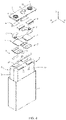
FIG. 4 is an exploded view of the secondary battery shown inFIG. 3 ; -
FIG. 5 is a schematic diagram of an electrode assembly according to some embodiments of this application; -
FIG. 6 is a sectional view of the electrode assembly shown inFIG. 5 ; -
FIG. 7 is a sectional view of the secondary battery shown inFIG. 3 ; -
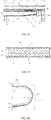
FIG. 8 is a local detailed view of a part indicated by a box A shown inFIG. 7 ; -
FIG. 9 is a local detailed view of a part indicated by a box B shown inFIG. 8 ; -
FIG. 10 is a local detailed view of a part indicated by a box C shown inFIG. 8 ; -
FIG. 11 is a local detailed view of a part indicated by a box D shown inFIG. 8 ; -
FIG. 12 is a local detailed view of a part indicated by a box E shown inFIG. 8 ; -
FIG. 13 is a local detailed view of a part indicated by a box F shown inFIG. 8 ; -
FIG. 14 is a schematic diagram of a first insulation member according to some embodiments of this application; -
FIG. 15 is an exploded view of the first insulation member shown inFIG. 14 ; -
FIG. 16 is a schematic diagram of a current collection member according to some embodiments of this application; -
FIG. 17 is a schematic diagram of a second insulation member according to some embodiments of this application; -
FIG. 18 is a schematic diagram of a prop member according to some embodiments of this application; and -
FIG. 19 is a schematic diagram of a secondary battery in an assembling process according to some embodiments of this application. - The drawings are not drawn to scale.
-
- 1: Cap plate;
- 11. Injection hole;
- 2. Electrode assembly;
- 21. Main body;
- 211. First surface
- 212. Second surface
- 213. Third surface;
- 22: Tab;
- 221. Connection portion;
- 222. Bend portion;
- 23. First electrode plate;
- 24. Second electrode plate;
- 25. Separator;
- 3. First insulation member;
- 31. First insulator;
- 32. Second insulator;
- 33. Third insulator;
- 331. First part;
- 332. Second part;
- 333. Inner piece;
- 334. Outer piece;
- 34. Fourth insulator;
- 4. Electrode terminal;
- 5. Current collection member;
- 51. First current collection portion;
- 52. Second current collection portion;
- 6. Second insulation member;
- 61. First overlayer;
- 62. Second overlayer;
- 63. Third overlayer;
- 7. Prop member;
- 71. First prop board;
- 72. Second prop board;
- 73. Third prop board;
- 8. Housing;
- 9. Rupture disk;
- 1000. Secondary battery;
- W. Weld region;
- X. Length direction;
- Y. Thickness direction; and
- Z. Height direction.
- To make the objectives, technical solutions, and advantages of this application clearer, the following describes this application in further detail with reference to accompanying drawings and embodiments. Understandably, the specific embodiments described herein are merely intended to explain this application, but are not intended to limit this application.
- In the context of this application, unless otherwise expressly specified, the terms such as "first", "second", "third", and "fourth" are for the sole purpose of description rather than indicating or implying any order of preference; the term "a plurality of" means two or more (including two); unless otherwise expressly specified, the term "connect" needs to be understood in a broad sense. For example, a "connection" may be a fixed connection, or a detachable connection, or an integrated connection, or an electrical connection or signal connection; or may be a direct connection or an indirect connection implemented through an intermediate medium. A person of ordinary skill in the art understands the specific meanings of the terms in this application according to the context.
- Understandably, in the context of this application, directional terms such as "on", "above", "under", and "below" described in the embodiments of this application are described from a perspective shown in the drawings, and are not to be understood as a limitation on the embodiments of this application. The following describes this application in further detail with reference to specific embodiments and accompanying drawings.
- The directional terms appearing in the following description indicate the directions shown in the drawings, but are not intended to limit specific structures in this application. In the context of this application, unless otherwise expressly specified, the terms "mount", "concatenate", and "connect" are understood in a broad sense. For example, a "connection" may be a fixed connection, a detachable connection, or an integrated connection, and may be a direct connection or an indirect connection implemented through an intermediary. A person of ordinary skill in the art can understand the specific meanings of the terms in this application according to specific situations.
- Embodiments of this application provide a device using a battery as a power supply. The battery is a secondary battery that is cyclically rechargeable and dischargeable. Generally, there are a plurality of secondary batteries in the device arranged in groups. Referring to
FIG. 1 , in some embodiments, the device may be a ship, a vehicle, or the like. The vehicle is an new energy vehicle, and may be a battery electric vehicle, or a hybrid electric vehicle, or a range-extended electric vehicle. A drive motor is disposed in a chassis of the vehicle. The drive motor is electrically connected to a secondary battery. The secondary battery provides electrical energy to the drive motor. The drive motor is connected to wheels on the chassis of the vehicle through a transmission mechanism to drive the vehicle to move. In some embodiments, the secondary battery is a lithium-ion battery. - An embodiment of this application further provides a battery module. In some embodiments, referring to
FIG. 2 , the battery module includes a plurality ofsecondary batteries 1000. The plurality ofsecondary batteries 1000 are arranged in sequence. In some embodiments, the battery module further includes a prop frame and a plurality of busbars. The prop frame accommodates and fixes the plurality ofsecondary batteries 1000. The plurality of busbars electrically connect the plurality ofsecondary batteries 1000 in series, in parallel, or in both series and parallel. - An embodiment of this application further provides a secondary battery that is cyclically rechargeable and dischargeable. Referring to
FIG. 3 andFIG. 4 , a secondary battery according to some embodiments includes a cap plate 1, anelectrode assembly 2, electrode terminals 4, and a housing 8. - The
electrode assembly 2 is a core member for the secondary battery to implement functions of charging and discharging. Referring toFIG. 6 , theelectrode assembly 2 includes afirst electrode plate 23, asecond electrode plate 24, and aseparator 25. Theseparator 25 separates thefirst electrode plate 23 from thesecond electrode plate 24. - In some embodiments, the
electrode assembly 2 may be a jelly-roll structure. Specifically, referring toFIG. 6 , there are onefirst electrode plate 23 and onesecond electrode plate 24, and thefirst electrode plate 23 and thesecond electrode plate 24 are strap-shaped structures. Thefirst electrode plate 23, theseparator 25, and thesecond electrode plate 24 are sequentially stacked and wound for at least two coils to form theelectrode assembly 2. Theelectrode assembly 2 is flat. - In some alternative embodiments, the
electrode assembly 2 may be a stacked structure. Specifically, a plurality offirst electrode plates 23 are disposed, and a plurality ofsecond electrode plates 24 are disposed. The plurality offirst electrode plates 23 and the plurality ofsecond electrode plates 24 are alternately stacked. Theseparator 25 separates thefirst electrode plate 23 from thesecond electrode plate 24. - The
first electrode plate 23 includes a first current collector and a first active material layer coated on a surface of the first current collector. The first current collector is a metal foil such as an aluminum foil. The first active material layer includes a ternary material, lithium manganate, or lithium iron phosphate. The first current collector includes a first coating region and a first blank region. A surface of the first coating region is coated with the first active material layer. No surface of the first blank region is coated with the first active material layer. In a jelly-roll electrode assembly 2, there are a plurality of first blank regions of thefirst electrode plate 23 that are stacked. - The
second electrode plate 24 includes a second current collector and a second active material layer coated on a surface of the second current collector. The second current collector is a metal foil such as a copper foil. The second active material layer contains graphite or silicon. The second current collector includes a second coating region and a second blank region. A surface of the second coating region is coated with the second active material layer. No surface of the second blank region is coated with the second active material layer. In a jelly-roll electrode assembly 2, there are a plurality of second blank regions of thesecond electrode plate 24 that are stacked. - Referring to
FIG. 5 , as seen from the appearance of theelectrode assembly 2, theelectrode assembly 2 includes amain body 21 andtabs 22 extending from themain body 21. There are twotabs 22. Specifically, themain body 21 includes a first coating region, a first active material layer, a separator 13, a second coating region, and a second active material layer. The twotabs 22 are a first tab and a second tab. The first tab includes the plurality of first blank regions that are stacked, and the second tab includes the plurality of second blank regions that are stacked. - In a secondary battery according to some embodiments, there are a plurality of
electrode assemblies 2. The plurality ofelectrode assemblies 2 are stacked in a thickness direction Y of the secondary battery. In some alternative embodiments, there may be oneelectrode assembly 2. - Referring to
FIG. 3 andFIG. 4 , the housing 8 is in a hexahedral shape or other shape. The housing 8 forms an accommodation cavity interiorly to accommodate theelectrode assembly 2 and an electrolytic solution. An opening is formed at one end of the housing 8 along a height direction Z. Theelectrode assembly 2 can be placed into the accommodation cavity of the housing 8 through the opening. The housing 8 may be made of a conductive metal material. In some embodiments, the housing 8 is made of aluminum or an aluminum alloy. - The cap plate 1 is connected to the housing 8 and covers the opening of the housing 8. The electrode terminals 4 are disposed on the cap plate 1. In some embodiments, the electrode terminals 4 are mounted to the cap plate 1 by using a fastener. The electrode terminals 4 protrude above the cap plate 1 for ease of connecting to the busbar.
- There are two electrode terminals 4. The two electrode terminals 4 are electrically connected to the first tab and the second tab respectively.
- Two electrode lead-out holes are disposed in the cap plate 1. The two electrode lead-out holes run through the cap plate 1 along a thickness direction of the cap plate 1. The two electrode terminals 4 cover the two electrode lead-out holes respectively. By disposing the electrode lead-out holes, it is convenient to implement the electrical connection between the tabs and the electrode terminals.
- In some embodiments, the secondary battery further includes
current collection members 5. Each of thecurrent collection members 5 is configured to connect the electrode terminal 4 and thetab 22. Referring toFIG. 4 andFIG. 16 , thecurrent collection member 5 includes a firstcurrent collection portion 51 and a secondcurrent collection portion 52. The firstcurrent collection portion 51 is connected to the electrode terminal 4, and the secondcurrent collection portion 52 is connected to thetab 22. Thesecond collection portion 52 is in a flat plate shape. The firstcurrent collection portion 51 protrudes beyond thesecond collection portion 52 toward the cap plate 1. The firstcurrent collection portion 51 extends into the electrode lead-out hole and is welded to the electrode terminal 4. - In a process of using the secondary battery, if the secondary battery is abused such as nail-penetrated, the
electrode assembly 2 will be short-circuited and generate a large amount of gas. The gas accumulates in the housing 8 and is prone to cause an explosion. Therefore, to improve safety performance of the secondary battery, a secondary battery according to some embodiments further includes a rupture disk 9. - A via hole is disposed on the cap plate 1. The rupture disk 9 is disposed on the cap plate 1 and seals the via hole. The rupture disk 9 can cover the via hole and separate internal space of the secondary battery from the outside, so as to prevent an electrolytic solution in the housing 8 from leaking through the via hole.
- When the
electrode assembly 2 is short-circuited, gas is released. As the gas increases, gas pressure inside the secondary battery increases gradually. The rupture disk 9 deforms under the action of the air pressure. When the air pressure inside the secondary battery reaches a given value, the rupture disk 9 breaks off at a fragile region. High-pressure gas bursts open the rupture disk 9 and is expelled out of the secondary battery, thereby achieving the purpose of pressure relief and reducing the risk of explosion. - An
injection hole 11 is disposed on the cap plate 1. In a process of forming a battery, an electrolytic solution is injected into the housing 8 through theinjection hole 11. After the injection process is completed, a sealing strip is welded onto the cap plate 1 to seal theinjection hole 11. - In this embodiment of this application, the
tab 22 is bent to make thetab 22 occupy a smaller space. Referring toFIG. 5 andFIG. 8 , in some embodiments, the bent tab (22) includes aconnection portion 221 and abend portion 222. Theconnection portion 221 is electrically connected to an electrode terminal 4. Thebend portion 222 is bent against theconnection portion 221 and is connected between theconnection portion 221 and themain body 21. Theconnection portion 221 is approximately parallel to a thickness direction of themain body 21. Theconnection portion 221 and thebend portion 222 each include a plurality of metal foil layers. - The
connection portion 221 may be directly connected to the electrode terminal 4 or may be connected to the electrode terminal 4 by thecurrent collection member 5. For ease of understanding the secondary battery according to this embodiment of this application, the following describes the secondary battery with reference to some embodiments in which aconnection portion 221 is connected to acurrent collection member 5. - When the
tab 22 is bent, stress concentration occurs at a joint between thetab 22 and thecurrent collection member 5. Because thetab 22 includes a plurality of metal foil layers, thetab 22 is prone to rupture at the joint between thetab 22 and thecurrent collection member 5 to impair a current-carrying capacity of thetab 22. In severe circumstances, an innermost metal foil layer of the connection portion 221 (that is, a metal foil layer closest to the main body 21) may break off thoroughly. The broken metal foil layer cannot be fixed, and is prone to be inserted into themain body 21, thereby causing a short-circuit risk. - The secondary battery according to some embodiments further includes a
first insulation member 3. Thefirst insulation member 3 is disposed at a side of theconnection portion 221 away from the cap plate 1. Thefirst insulation member 3 includes afirst insulator 31 connected to theconnection portion 221. Theconnection portion 221 is configured to connect to thecurrent collection member 5. Therefore, when thetab 22 is bent, theconnection portion 221 is at high risk of rupturing. Thefirst insulator 31 can fix theconnection portion 221, disperse a stress transmitted to theconnection portion 221, and reduce the risk of rupturing theconnection portion 221. In some embodiments, even if the innermost metal foil layer of theconnection portion 221 is thoroughly broken off, thefirst insulator 31 can still connect the broken metal foils together to avoid inserting into themain body 21, thereby reducing the short-circuit risk. - The
first insulation member 3 further includes asecond insulator 32 connected to themain body 21. Thesecond insulator 32 is disposed between theconnection portion 221 and themain body 21. In some embodiments, thesecond insulator 32 is connected to afirst surface 211 of themain body 21, the first surface being oriented toward the cap plate 1. - Referring to
FIG. 5 and FIG. 6 , in order to completely separate the first active material layer from the second active material layer, both ends of theseparator 25 extend beyond the first active material layer and the second active material layer along a height direction Z. After theseparator 25 is wound into shape, an end that is of theseparator 25 and that is close to the cap plate 1 approximately forms a surface. The surface is thefirst surface 211 of themain body 21. Because thefirst surface 211 is formed by the end of theseparator 25, some gaps exist on thefirst surface 211. - The
tab 22 is formed by stacking a plurality of blank regions, and the plurality of blank regions are usually of the same size. When a plurality of blank regions are stacked together, ends that are of the plurality of blank regions and that are away from themain body 21 are jagged and untidy. To ensure high connection strength between thetab 22 and thecurrent collection member 5, the ends that are of the plurality of blank regions and that are away from themain body 21 are usually not directly fixed to thecurrent collection member 5. In other words, the ends that are of theconnection portion 221 and that are away from thebend portion 222 are not directly fixed to thecurrent collection member 5. - In order to make the
tab 22 occupy a smaller space, the spacing between theconnection portion 221 and themain body 21 is relatively small. The end that is of theconnection portion 221 and that is away from thebend portion 222 is prone to be bent and inserted into themain body 21 through the gap on thefirst surface 211, thereby causing a short-circuit risk. In this embodiment of this application, thesecond insulator 32 can separate theconnection portion 221 from themain body 21, so that the end that is of theconnection portion 221 and that is away from thebend portion 222 is prevented from being inserted into themain body 21, and the short-circuit risk is reduced. - In some embodiments, in an electrolyte injection process, the electrolytic solution causes an impact onto the
first surface 211 of themain body 21. Thefirst surface 211 is formed by the end that is of theseparator 25 and that is close to the cap plate 1. Therefore, when theseparator 25 is impacted by the electrolytic solution, theseparator 25 may bend inward, so that theseparator 25 is unable to completely separate thefirst electrode plate 23 from thesecond electrode plate 24, thereby causing a short-circuit risk. When impacted by the electrolytic solution, thefirst electrode plate 23 and thesecond electrode plate 24 may also be wrinkled and deformed, thereby affecting the performance of theelectrode assembly 2. - In a secondary battery according to some embodiments, a projection of the
injection hole 11 on thefirst surface 211 is at least partly covered by thesecond insulator 32. In some embodiments, a projection of theinjection hole 11 on thefirst surface 211 is fully covered by thesecond insulator 32. Thesecond insulator 32 separates thefirst surface 211 from theinjection hole 11 to prevent the electrolytic solution from directly impacting thefirst surface 211, and reduce the deformation of theseparator 25 and the electrode plate. - The
first insulation member 3 further includes athird insulator 33 connected between thefirst insulator 31 and thesecond insulator 32. Thethird insulator 33 connects thefirst insulator 31 and thesecond insulator 32 together to improve the connection strength between thefirst insulator 31 and thesecond insulator 32 on theelectrode assembly 2, and reduce the peel-off risk. In some embodiments, if thefirst insulator 31 and thesecond insulator 32 are disposed discretely, thefirst insulator 31 and thesecond insulator 32 need to be connected to theelectrode assembly 2 through two processes respectively. By disposing thethird insulator 33, one process is enough to connect thefirst insulation member 3 to theelectrode assembly 2, thereby improving assembling efficiency. - At least a part of the
bend portion 222 is not fixed to thefirst insulation member 3. In other words, at least a part of the surface that is of thebend portion 222 and that is oriented toward thefirst insulation member 3 is not fixed to thefirst insulation member 3. Further, at least a part of the surface that is of thebend portion 222 and that is oriented toward thefirst insulation member 3 is covered by thethird insulator 33 and not fixed to thethird insulator 33. - If the
bend portion 222 is wholly fixed to the first insulation member 3 (for example, fixed to the third insulator 33), then when thetab 22 is bent, thefirst insulation member 3 will pull the innermost metal foil layer of thebend portion 222, and the innermost metal foil layer of thebend portion 222 is at risk of fracturing. However, in this embodiment of this application, at least a part of thebend portion 222 is not fixed to thefirst insulation member 3. Therefore, the part that is of thebend portion 222 and that is not fixed to thefirst insulation member 3 can release the stress during the bending of thetab 22, thereby reducing a tensile force exerted by thefirst insulation member 3 on thebend portion 222 and reducing the risk of fracturing thebend portion 222. - In a secondary battery according to some embodiments, referring to
FIG. 10 ,FIG. 11 ,FIG. 14, and FIG. 15 , thethird insulator 33 includes afirst part 331 and asecond part 332. Thefirst part 331 is connected between thefirst insulator 31 and thesecond part 332. Thefirst part 331 is fixed to thebend portion 222, and thesecond part 332 covers a part of thebend portion 222 and is not fixed to thebend portion 222. Thefirst part 331 is closer to the joint between theconnection portion 221 and thecurrent collection member 5 than thesecond part 332. Therefore, in some embodiments, thefirst part 331 is connected to thebend portion 222, so as to reduce the risk of fracturing theconnection portion 221. In some embodiments, even if the innermost metal foil layer of theconnection portion 221 is completely broken off, thefirst insulator 31 and thefirst part 331 can connect the broken metal foils together, thereby avoiding being inserted into themain body 21. - In some embodiments, at least a part of the
first part 331 is arc-shaped. Thetab 22 may be bent along thefirst part 331. - In a secondary battery according to some embodiments, referring to
FIG. 14 and FIG. 15 , thethird insulator 33 includes aninner piece 333 and anouter piece 334 fixed to theinner piece 333. Theinner piece 333 is disposed between theouter piece 334 andbend portion 222. Theinner piece 333 is not fixed to thebend portion 222. Both theinner piece 333 and theouter piece 334 are single-sided adhesive tape. Theinner piece 333 and theouter piece 334 are directly bonded together. A surface that is of theinner piece 333 and that is away from theouter piece 334 is smooth and non-adhesive, so that theinner piece 333 is not fixed to thebend portion 222. - In a secondary battery according to some embodiments, referring to
FIG. 14 and FIG. 15 , the size of theouter piece 334 is larger than the size of theinner piece 333. In other words, theinner piece 333 covers just a part of theouter piece 334. A part that is of theouter piece 334 and that extends beyond theinner piece 333 is directly bonded onto thebend portion 222. Specifically, a part that is of theouter piece 334 and that overlaps theinner piece 333 combines with theinner piece 333 to form thesecond part 332 that is not fixed to thebend portion 222. The part that is of theouter piece 334 and that extends beyond theinner piece 333 forms thefirst part 331 that is fixed to thebend portion 222. - In a secondary battery according to some embodiments, the
third insulator 33 may be not fixed to thebend portion 222 at all. In this case, the size of theouter piece 334 is equal to the size of theinner piece 333, and theouter piece 334 completely overlaps theinner piece 333. - In a secondary battery according to some embodiments, the
first insulator 31 is bonded to theconnection portion 221, and thesecond insulator 32 is bonded to themain body 21. Both thefirst insulator 31 and thesecond insulator 32 are single-sided adhesive tape. - In a secondary battery according to some embodiments, the
first insulator 31, theouter piece 334, and thesecond insulator 32 are integrated into a whole. Thefirst insulator 31, theouter piece 334, and thesecond insulator 32 are different parts of one piece of single-sided adhesive tape. Theinner piece 333 is another piece of single-sided adhesive tape of a smaller size. In this embodiment of this application, two pieces of single-sided adhesive tape of different sizes are bonded together to form afirst insulation member 3 that is adhesive in a specific region. - In a secondary battery according to some embodiments, referring to
FIG. 8 , thesecond insulator 32 extends beyond theconnection portion 221 along a direction in which thebend portion 222 points to thethird insulator 33. In this case, on thefirst surface 211, a projection of the end that is of theconnection portion 221 and that is away from thebend portion 222 at least partly overlaps a projection of thesecond insulator 32. Thesecond insulator 32 can separate theconnection portion 221 from themain body 21, so that the end that is of theconnection portion 221 and that is away from thebend portion 222 is prevented from being inserted into themain body 21, and the short-circuit risk is reduced. - In a secondary battery according to some embodiments, referring to
FIG. 12 , thefirst insulation member 3 further includes afourth insulator 34. Thefourth insulator 34 is connected to an end of thesecond insulator 32, the end being away from thethird insulator 33. In a thickness direction of themain body 21, thefourth insulator 34 is connected to the outside of themain body 21. Themain body 21 contains asecond surface 212 and athird surface 213. Thesecond surface 212 and thethird surface 213 are disposed opposite to each other along the thickness direction of themain body 21. Thesecond surface 212 is located at a side that is of thebend portion 222 and that is close to thethird insulator 33. Thethird surface 213 is located at a side of thebend portion 222, the side being away from thethird insulator 33. In some embodiments, thefourth insulator 34 is bonded to thesecond surface 212. Thefourth insulator 34 and thethird insulator 33 are integrated into a whole. - The
fourth insulator 34 disposed can increase the connection strength between the entirefirst insulation member 3 and theelectrode assembly 2, and reduce the risk of peeling off thefirst insulation member 3 from theelectrode assembly 2 under the immersion of the electrolytic solution. - In a secondary battery according to some embodiments, referring to
FIG. 8 and FIG. 9 , thecurrent collection member 5 is welded to theconnection portion 221 to form a weld region W. A plurality of metal foil layers of theconnection portion 221 are connected to thecurrent collection member 5 by welding. At an edge of the weld region W, each metal foil layer is of relatively low strength, and is at risk of fracturing when being under a force. In this embodiment of this application, thefirst insulator 31 covers the weld region W from a side of the weld region W, the side being oriented toward themain body 21. The region of thecurrent collection member 5, to which theconnection portion 221 is welded, can be connected with an unwelded region by thefirst insulator 31, so as to reduce the risk of fracturing theconnection portion 221 in a process of bending thetab 22. - In some embodiments, after the weld region W is formed, some metal particles may remain on the surface of the weld region W. The metal particles falling into the
main body 21 may cause a short-circuit risk. Thefirst insulator 31 can fix the metal particles onto the weld region W to prevent the metal particles from falling, and reduce the short-circuit risk. - The
connection portion 221 is located at a side of the secondcurrent collection portion 52 away from the cap plate 1. Theconnection portion 221 is welded to the secondcurrent collection portion 52 to form the weld region W. - In a secondary battery according to some embodiments, referring to
FIG. 8 andFIG. 13 , the secondary battery further includes a second insulation member 6. The second insulation member 6 covers the weld region W from a side of the weld region W, the side being oriented toward the cap plate 1. The second insulation member 6 is bonded to a surface that is of the weld region W and that is oriented toward the cap plate 1, so as to fix the metal particles on the surface of the weld region W. - The second insulation member 6 includes a
first overlayer 61 and asecond overlayer 62. Thefirst overlayer 61 covers the weld region W from a side of the weld region W, the side being oriented toward the cap plate 1. Thesecond overlayer 62 is connected to thefirst overlayer 61 and is bent against thefirst overlayer 61. Thefirst overlayer 61 is bonded to a surface of the welding region W, the surface being oriented toward the cap plate 1. Thesecond overlayer 62 is located at a side of thebend portion 222 away from thethird insulator 33, and is connected to thebend portion 222. - In a process of placing the
electrode assembly 2 into the housing 8, there is a risk that an edge of the housing 8 contacts thebend portion 222 due to process errors. With thesecond overlayer 62 disposed, thebend portion 222 can be separated from the housing 8, thereby preventing thebend portion 222 from being scratched by the housing 8, and ensuring the current-carrying capacity of thebend portion 222. - The second insulation member 6 further includes a
third overlayer 63. Thethird overlayer 63 extends from an end that is of thesecond overlayer 62 and that is away from thefirst overlayer 61. Thethird overlayer 63 is connected to themain body 21. In some embodiments, thethird overlayer 63 is bonded to athird surface 213 of themain body 21. - The
third overlayer 63 disposed can increase the connection strength between the entire second insulation member 6 and theelectrode assembly 2, and reduce the risk of peeling off the second insulation member 6 from theelectrode assembly 2 under the immersion of the electrolytic solution. In some embodiments, thethird overlayer 63 can reduce the risks such as scratch of themain body 21 by the housing 8. - In some embodiments, referring to
FIG. 17 , the second insulation member 6 is single-sided adhesive tape. Thefirst overlayer 61, thesecond overlayer 62, and thethird overlayer 63 are integrated into a whole. - In a secondary battery according to some embodiments, referring to
FIG. 4 ,FIG. 8 , andFIG. 18 , the secondary battery further includes aprop member 7. Theprop member 7 includes afirst prop board 71, asecond prop board 72, and athird prop board 73. Thefirst prop board 71 is disposed at a side of thefirst insulator 31 away from the cap plate 1. Thesecond prop board 72 is located between thefirst prop board 71 and thesecond insulator 32. Thethird prop board 73 is connected between thefirst prop board 71 and thesecond prop board 72. Theprop member 7 is formed by bending a sheet material. Under the action of an inherent elastic force, thefirst prop board 71 can prop theconnection portion 221 from a lower side. In this way, the end that is of theconnection portion 221 and that is away from thebend portion 222 is prevented from being bent downward and inserted into themain body 21. The material of theprop member 7 is PET. - In some embodiments, the
prop member 7 is bonded to thefirst insulation member 3. Referring toFIG. 10 andFIG 11 , thethird prop board 73 fits snugly with and is bonded to thethird insulator 33. When thetab 22 is bent, thethird prop board 73 can support shaping of thebend portion 222 of thetab 22, thereby reducing the risk of inserting thebend portion 222 into themain body 21. - Under the action of an inherent elastic force of the
prop member 7, the end that is of thesecond prop board 72 and that is away from thethird prop board 73 exerts a force on thefirst surface 211. That is, the end of thethird prop board 73 is prone to be inserted into themain body 21 to cause a short-circuit risk. In this embodiment of this application, referring toFIG. 12 , along a direction in which thebend portion 222 points to thethird insulator 33, thesecond insulator 32 extends beyond thesecond prop board 72. Thesecond insulator 32 can separate thesecond prop board 72 from themain body 21, thereby preventing the end of thethird prop board 73 from being inserted into themain body 21. - Although this application has been described with reference to optional embodiments, various improvements may be made to the embodiments without departing from the scope of this application, and the components therein may be replaced with equivalents. Particularly, to the extent that no structural conflict exists, various technical features mentioned in various embodiments can be combined in any manner. This application is not limited to the specific embodiments disclosed herein, but includes all technical solutions falling within the scope of the claims.
Claims (13)
- A secondary battery, comprising:a cap plate (1);electrode terminals (4), disposed on the cap plate (1);an electrode assembly (2), comprising a main body (21) and tabs (22) extending from the main body (21), wherein each of the tabs (22) comprises a connection portion (221) and a bend portion (222), the connection portion (221) is electrically connected to one of the electrode terminals (4), and the bend portion (222) is bent against the connection portion (221) and is connected between the connection portion (221) and the main body (21); anda first insulation member (3), disposed at a side that is of the connection portion (221) and that is away from the cap plate (1), wherein the first insulation member (3) comprises a first insulator (31) connected to the connection portion (221), a second insulator (32) connected to the main body (21), and a third insulator (33) connected between the first insulator (31) and the second insulator (32), and at least a part of the bend portion (222) is not fixed to the first insulation member (3).
- The secondary battery according to claim 1, whereinthe third insulator (33) comprises a first part (331) and a second part (332), and the first part (331) is connected between the first insulator (31) and the second part (332); andthe first part (331) is fixed to the bend portion (222), and the second part (332) covers a part of the bend portion (222) and is not fixed to the bend portion (222).
- The secondary battery according to claim 1 or 2, wherein
the third insulator (33) comprises an inner piece (333) and an outer piece (334) fixed to the inner piece (333), the inner piece (333) is disposed between the outer piece (334) and the bend portion (222), and the inner piece (333) is not fixed to the bend portion (222). - The secondary battery according to claim 3, wherein the first insulator (31) is bonded to the connection portion (221), the outer piece (334) is bonded to the inner piece (333), and the second insulator (32) is bonded to the main body (21).
- The secondary battery according to any one of claims 1 to 4, wherein
along a direction in which the bend portion (222) points to the third insulator (33), the second insulator (32) extends beyond the connection portion (221). - The secondary battery according to claim 5, whereinthe first insulation member (3) further comprises a fourth insulator (34), and the fourth insulator (34) is connected to an end of the second insulator (32), the end being away from the third insulator (33); andin a thickness direction of the main body (21), the fourth insulator (34) is connected to the outside of the main body (21).
- The secondary battery according to any one of claims 1 to 6, whereinthe secondary battery further comprises current collection members (5), and each of the current collection members (5) is configured to connect the electrode terminal (4) and the tab (22); andthe current collection member (5) is welded to the connection portion (221) to form a weld region (W), and the first insulator (31) covers the weld region (W) from a side of the weld region (W), the side being oriented toward the main body (21).
- The secondary battery according to claim 7, wherein
the secondary battery further comprises a second insulation member (6), and the second insulation member (6) covers the weld region (W) from a side of the weld region (W), the side being oriented toward the cap plate (1). - The secondary battery according to claim 8, whereinthe second insulation member (6) comprises a first overlayer (61) and a second overlayer (62), the first overlayer (61) covers the weld region (W) from a side of the weld region (W), the side being oriented toward the cap plate (1); and the second overlayer (62) is connected to the first overlayer (61) and is bent against the first overlayer (61); andthe second overlayer (62) is located at a side of the bend portion (222) away from the third insulator (33), and is connected to the bend portion (222).
- The secondary battery according to claim 9, wherein
the second insulation member (6) further comprises a third overlayer (63), the third overlayer (63) extends from an end that is of the second overlayer (62) and that is away from the first overlayer (61), and the third overlayer (63) is connected to the main body (21). - The secondary battery according to any one of claims 1 to 10, whereinthe secondary battery further comprises a prop member (7), the prop member (7) comprises a first prop board (71), a second prop board (72), and a third prop board (73), the first prop board (71) is disposed at a side of the first insulator (31) away from the cap plate (1), the second prop board (72) is located between the first prop board (71) and the second insulator (32), and the third prop board (73) is connected between the first prop board (71) and the second prop board (72); andalong a direction in which the bend portion (222) points to the third insulator (33), the second insulator (32) extends beyond the second prop board (72).
- A battery module, comprising the secondary battery according to any one of claims 1 to 11, wherein the secondary battery is plural in number.
- A device using a battery as a power supply, wherein the battery is the secondary battery according to any one of claims 1 to 11.
Applications Claiming Priority (2)
| Application Number | Priority Date | Filing Date | Title |
|---|---|---|---|
| CN202010054531.4A CN112332039B (en) | 2020-01-17 | 2020-01-17 | Secondary battery, battery module, and device using battery as power source |
| PCT/CN2020/139185 WO2021143481A1 (en) | 2020-01-17 | 2020-12-24 | Secondary battery, battery module, and device using battery as power source |
Publications (4)
| Publication Number | Publication Date |
|---|---|
| EP3989352A1 true EP3989352A1 (en) | 2022-04-27 |
| EP3989352A4 EP3989352A4 (en) | 2023-01-25 |
| EP3989352B1 EP3989352B1 (en) | 2024-08-21 |
| EP3989352B8 EP3989352B8 (en) | 2024-10-16 |
Family
ID=74302840
Family Applications (1)
| Application Number | Title | Priority Date | Filing Date |
|---|---|---|---|
| EP20913277.8A Active EP3989352B8 (en) | 2020-01-17 | 2020-12-24 | Secondary battery, battery module, and device using battery as power supply |
Country Status (9)
| Country | Link |
|---|---|
| US (2) | US12463297B2 (en) |
| EP (1) | EP3989352B8 (en) |
| JP (1) | JP7587579B2 (en) |
| KR (1) | KR102848263B1 (en) |
| CN (1) | CN112332039B (en) |
| ES (1) | ES2994847T3 (en) |
| FI (1) | FI3989352T3 (en) |
| HU (1) | HUE068821T2 (en) |
| WO (1) | WO2021143481A1 (en) |
Cited By (2)
| Publication number | Priority date | Publication date | Assignee | Title |
|---|---|---|---|---|
| EP4369465A1 (en) * | 2022-11-11 | 2024-05-15 | Shenzhen Hithium Energy Storage Technology Co., Ltd. | Energy storage device and electronic device |
| EP4579929A4 (en) * | 2022-10-27 | 2025-12-24 | Contemporary Amperex Technology Hong Kong Ltd | BATTERY CELL, BATTERY AND ELECTRICAL DEVICE |
Families Citing this family (15)
| Publication number | Priority date | Publication date | Assignee | Title |
|---|---|---|---|---|
| CN112332039B (en) | 2020-01-17 | 2021-10-22 | 宁德时代新能源科技股份有限公司 | Secondary battery, battery module, and device using battery as power source |
| CN113853709B (en) * | 2020-07-30 | 2023-06-20 | 东莞新能安科技有限公司 | Electrochemical devices and electronic devices |
| WO2022226971A1 (en) * | 2021-04-30 | 2022-11-03 | 宁德时代新能源科技股份有限公司 | Battery cell, fabrication method and fabrication system therefor, battery, and electrical apparatus |
| CN215266598U (en) * | 2021-07-30 | 2021-12-21 | 宁德时代新能源科技股份有限公司 | Battery cells, batteries and electrical devices |
| WO2023050162A1 (en) | 2021-09-29 | 2023-04-06 | 宁德时代新能源科技股份有限公司 | Battery cell, battery, electric device, and method and device for manufacturing battery cell |
| CN216354646U (en) * | 2021-11-30 | 2022-04-19 | 宁德时代新能源科技股份有限公司 | Power battery |
| CN115172998A (en) * | 2022-07-26 | 2022-10-11 | 上海兰钧新能源科技有限公司 | Secondary battery and method for manufacturing secondary battery |
| CN223898544U (en) * | 2022-09-13 | 2026-02-10 | 宁德时代新能源科技股份有限公司 | Battery cells, batteries and electrical devices |
| WO2024148468A1 (en) * | 2023-01-09 | 2024-07-18 | 宁德时代新能源科技股份有限公司 | Battery cell, battery and electric device |
| CN119627375A (en) * | 2023-09-12 | 2025-03-14 | 宁德时代新能源科技股份有限公司 | Battery cells, batteries and electrical devices |
| CN221239756U (en) * | 2023-09-28 | 2024-06-28 | 宁德时代新能源科技股份有限公司 | Battery cell, battery and electricity utilization device |
| CN222015634U (en) * | 2023-09-28 | 2024-11-15 | 宁德时代新能源科技股份有限公司 | Battery cells, batteries and electrical devices |
| CN118431682B (en) * | 2024-07-04 | 2024-10-08 | 江苏正力新能电池技术股份有限公司 | Battery connecting piece, battery, electric equipment and tab welding method |
| WO2026043279A1 (en) * | 2024-08-21 | 2026-02-26 | 주식회사 엘지에너지솔루션 | Secondary battery, and battery module, battery pack, and transportation means comprising same |
| CN119419458A (en) * | 2025-01-07 | 2025-02-11 | 宁德时代新能源科技股份有限公司 | Electric device, battery device, battery cell and manufacturing method thereof |
Family Cites Families (28)
| Publication number | Priority date | Publication date | Assignee | Title |
|---|---|---|---|---|
| JPH04147517A (en) | 1990-10-09 | 1992-05-21 | Fujikura Ltd | Shielded tape electric wire |
| JPH10154505A (en) * | 1996-11-22 | 1998-06-09 | Matsushita Electric Ind Co Ltd | Cylindrical sealed battery |
| US6632538B1 (en) | 1998-02-05 | 2003-10-14 | Dai Nippon Printing Co., Ltd. | Sheet for cell and cell device |
| JP4780598B2 (en) * | 2004-09-29 | 2011-09-28 | 日立マクセルエナジー株式会社 | Sealed prismatic battery |
| US20080289171A1 (en) | 2007-05-22 | 2008-11-27 | Jason Cheng | Method for assembling a stacked plate electrochemical device |
| US8592079B2 (en) * | 2011-07-28 | 2013-11-26 | Samsung Sdi Co., Ltd. | Rechargeable battery |
| US9634299B2 (en) * | 2011-09-06 | 2017-04-25 | Samsung Sdi Co., Ltd. | Rechargeable battery |
| JP2014112492A (en) * | 2012-12-05 | 2014-06-19 | Toyota Industries Corp | Power storage device |
| KR101342696B1 (en) | 2012-12-07 | 2013-12-17 | 한화케미칼 주식회사 | Lithium ion battery and fabrication method thereof |
| US9660249B2 (en) | 2013-10-01 | 2017-05-23 | Samsung Sdi Co., Ltd. | Rechargeable battery having a fuse |
| JP6079592B2 (en) * | 2013-12-02 | 2017-02-15 | 株式会社豊田自動織機 | Power storage device |
| KR102284569B1 (en) * | 2014-10-07 | 2021-08-03 | 삼성에스디아이 주식회사 | Rechargeable battery and method of manufacturing the same |
| KR102273643B1 (en) * | 2014-10-07 | 2021-07-07 | 삼성에스디아이 주식회사 | Rechargeable battery |
| CN205248346U (en) * | 2015-12-30 | 2016-05-18 | 安徽贵博新能科技有限公司 | Laminate polymer battery standard module box structure |
| CN205609629U (en) * | 2016-04-28 | 2016-09-28 | 宁德时代新能源科技股份有限公司 | Energy memory encapsulates subassembly |
| KR102264700B1 (en) * | 2016-07-25 | 2021-06-11 | 삼성에스디아이 주식회사 | Rechargeable battery |
| KR102260826B1 (en) * | 2016-09-06 | 2021-06-03 | 삼성에스디아이 주식회사 | Rechargeable battery |
| CN206250261U (en) | 2016-12-02 | 2017-06-13 | 宁德时代新能源科技股份有限公司 | Secondary cell |
| CN206432317U (en) * | 2017-02-17 | 2017-08-22 | 宁德时代新能源科技股份有限公司 | Battery core and battery |
| CN109698385B (en) * | 2017-10-20 | 2024-06-18 | 宁德时代新能源科技股份有限公司 | Secondary battery |
| CN111785904B (en) | 2018-01-12 | 2021-08-17 | 宁德时代新能源科技股份有限公司 | Secondary batteries and automobiles |
| JP2019145271A (en) * | 2018-02-19 | 2019-08-29 | 株式会社豊田自動織機 | Power storage device and manufacturing method of power storage device |
| CN208189697U (en) | 2018-03-23 | 2018-12-04 | 比亚迪股份有限公司 | Single battery, battery modules, power battery and electric car |
| CN209561523U (en) * | 2018-12-28 | 2019-10-29 | 蜂巢能源科技有限公司 | Multilayer structure of power battery connecting sheet and power cover |
| CN209786120U (en) * | 2019-05-31 | 2019-12-13 | 宁德时代新能源科技股份有限公司 | Secondary batteries and battery modules |
| CN209766569U (en) * | 2019-06-19 | 2019-12-10 | 宁德时代新能源科技股份有限公司 | secondary battery and battery module |
| CN210467893U (en) | 2019-08-07 | 2020-05-05 | 江苏时代新能源科技有限公司 | Secondary battery and battery pack |
| CN112332039B (en) | 2020-01-17 | 2021-10-22 | 宁德时代新能源科技股份有限公司 | Secondary battery, battery module, and device using battery as power source |
-
2020
- 2020-01-17 CN CN202010054531.4A patent/CN112332039B/en active Active
- 2020-12-24 FI FIEP20913277.8T patent/FI3989352T3/en active
- 2020-12-24 KR KR1020227016530A patent/KR102848263B1/en active Active
- 2020-12-24 WO PCT/CN2020/139185 patent/WO2021143481A1/en not_active Ceased
- 2020-12-24 JP JP2022528650A patent/JP7587579B2/en active Active
- 2020-12-24 HU HUE20913277A patent/HUE068821T2/en unknown
- 2020-12-24 EP EP20913277.8A patent/EP3989352B8/en active Active
- 2020-12-24 ES ES20913277T patent/ES2994847T3/en active Active
-
2022
- 2022-03-24 US US17/702,908 patent/US12463297B2/en active Active
-
2025
- 2025-08-07 US US19/294,111 patent/US20250364704A1/en active Pending
Cited By (2)
| Publication number | Priority date | Publication date | Assignee | Title |
|---|---|---|---|---|
| EP4579929A4 (en) * | 2022-10-27 | 2025-12-24 | Contemporary Amperex Technology Hong Kong Ltd | BATTERY CELL, BATTERY AND ELECTRICAL DEVICE |
| EP4369465A1 (en) * | 2022-11-11 | 2024-05-15 | Shenzhen Hithium Energy Storage Technology Co., Ltd. | Energy storage device and electronic device |
Also Published As
| Publication number | Publication date |
|---|---|
| US20250364704A1 (en) | 2025-11-27 |
| KR20220084357A (en) | 2022-06-21 |
| WO2021143481A1 (en) | 2021-07-22 |
| US20220216574A1 (en) | 2022-07-07 |
| EP3989352B1 (en) | 2024-08-21 |
| CN112332039A (en) | 2021-02-05 |
| JP2023502115A (en) | 2023-01-20 |
| FI3989352T3 (en) | 2024-11-11 |
| US12463297B2 (en) | 2025-11-04 |
| ES2994847T3 (en) | 2025-02-03 |
| EP3989352A4 (en) | 2023-01-25 |
| JP7587579B2 (en) | 2024-11-20 |
| EP3989352B8 (en) | 2024-10-16 |
| HUE068821T2 (en) | 2025-01-28 |
| CN112332039B (en) | 2021-10-22 |
| KR102848263B1 (en) | 2025-08-20 |
Similar Documents
| Publication | Publication Date | Title |
|---|---|---|
| US12463297B2 (en) | Secondary battery, battery module, and device using battery as power supply | |
| US12347890B2 (en) | Secondary battery, battery module, and device using secondary battery as power supply | |
| US20230123940A1 (en) | Battery cell, battery and power consuming device | |
| US11489236B2 (en) | Rechargeable battery | |
| US20240322351A1 (en) | Battery cell, battery and electrical apparatus | |
| CN217158290U (en) | Electrode assembly, battery cell, battery and power consumption device | |
| EP4310977A1 (en) | Electrode sheet and preparation method therefor, battery, and electronic device | |
| US20240154263A1 (en) | Electrode assembly and traction battery | |
| WO2023185288A1 (en) | Battery | |
| US11929510B2 (en) | Secondary battery and manufacturing method thereof, battery module, and apparatus | |
| US20230318151A1 (en) | Battery | |
| US20230261334A1 (en) | Battery cell, battery, electric device, and manufacturing method and device of battery cell | |
| CN212517274U (en) | Battery and device using battery | |
| EP4089800A1 (en) | Battery cell and manufacturing method and system therefor, battery, and electric device | |
| US12315960B2 (en) | Current collecting member and manufacturing method thereof, secondary battery and manufacturing method thereof, battery module, and apparatus | |
| CN213150965U (en) | Batteries and devices using batteries | |
| CN213636220U (en) | Batteries and Electronic Devices | |
| CN211376679U (en) | Secondary battery, top cover assembly for secondary battery, battery module and device using secondary battery as power supply | |
| KR20050121905A (en) | Secondary battery and electrodes assembly using the same | |
| CN223871463U (en) | Battery monomer, battery device and power utilization device | |
| CN223993366U (en) | Battery cell, battery and electricity utilization device | |
| EP4693710A1 (en) | Housing assembly, battery cell, battery, and electrical apparatus |
Legal Events
| Date | Code | Title | Description |
|---|---|---|---|
| STAA | Information on the status of an ep patent application or granted ep patent |
Free format text: STATUS: THE INTERNATIONAL PUBLICATION HAS BEEN MADE |
|
| PUAI | Public reference made under article 153(3) epc to a published international application that has entered the european phase |
Free format text: ORIGINAL CODE: 0009012 |
|
| STAA | Information on the status of an ep patent application or granted ep patent |
Free format text: STATUS: REQUEST FOR EXAMINATION WAS MADE |
|
| 17P | Request for examination filed |
Effective date: 20220119 |
|
| AK | Designated contracting states |
Kind code of ref document: A1 Designated state(s): AL AT BE BG CH CY CZ DE DK EE ES FI FR GB GR HR HU IE IS IT LI LT LU LV MC MK MT NL NO PL PT RO RS SE SI SK SM TR |
|
| RAP3 | Party data changed (applicant data changed or rights of an application transferred) |
Owner name: CONTEMPORARY AMPEREX TECHNOLOGY CO., LIMITED |
|
| A4 | Supplementary search report drawn up and despatched |
Effective date: 20221222 |
|
| RIC1 | Information provided on ipc code assigned before grant |
Ipc: H01M 50/593 20210101ALI20221216BHEP Ipc: H01M 50/536 20210101ALI20221216BHEP Ipc: H01M 50/534 20210101ALI20221216BHEP Ipc: H01M 50/209 20210101ALI20221216BHEP Ipc: H01M 10/0587 20100101ALI20221216BHEP Ipc: H01M 50/15 20210101ALI20221216BHEP Ipc: H01M 50/533 20210101AFI20221216BHEP |
|
| DAV | Request for validation of the european patent (deleted) | ||
| DAX | Request for extension of the european patent (deleted) | ||
| STAA | Information on the status of an ep patent application or granted ep patent |
Free format text: STATUS: EXAMINATION IS IN PROGRESS |
|
| 17Q | First examination report despatched |
Effective date: 20230904 |
|
| GRAP | Despatch of communication of intention to grant a patent |
Free format text: ORIGINAL CODE: EPIDOSNIGR1 |
|
| STAA | Information on the status of an ep patent application or granted ep patent |
Free format text: STATUS: GRANT OF PATENT IS INTENDED |
|
| INTG | Intention to grant announced |
Effective date: 20240313 |
|
| GRAS | Grant fee paid |
Free format text: ORIGINAL CODE: EPIDOSNIGR3 |
|
| GRAA | (expected) grant |
Free format text: ORIGINAL CODE: 0009210 |
|
| STAA | Information on the status of an ep patent application or granted ep patent |
Free format text: STATUS: THE PATENT HAS BEEN GRANTED |
|
| AK | Designated contracting states |
Kind code of ref document: B1 Designated state(s): AL AT BE BG CH CY CZ DE DK EE ES FI FR GB GR HR HU IE IS IT LI LT LU LV MC MK MT NL NO PL PT RO RS SE SI SK SM TR |
|
| RAP3 | Party data changed (applicant data changed or rights of an application transferred) |
Owner name: CONTEMPORARY AMPEREX TECHNOLOGY CO., LIMITED |
|
| REG | Reference to a national code |
Ref country code: GB Ref legal event code: FG4D |
|
| REG | Reference to a national code |
Ref country code: CH Ref legal event code: EP |
|
| REG | Reference to a national code |
Ref country code: DE Ref legal event code: R096 Ref document number: 602020036452 Country of ref document: DE |
|
| REG | Reference to a national code |
Ref country code: IE Ref legal event code: FG4D |
|
| REG | Reference to a national code |
Ref country code: DE Ref legal event code: R081 Ref document number: 602020036452 Country of ref document: DE Owner name: CONTEMPORARY AMPEREX TECHNOLOGY (HONG KONG) LI, HK Free format text: FORMER OWNER: CONTEMPORARY AMPEREX TECHNOLOGY CO., LIMITED, NINGDE CITY, FUJIAN, CN |
|
| REG | Reference to a national code |
Ref country code: CH Ref legal event code: PK Free format text: BERICHTIGUNG B8 |
|
| RAP2 | Party data changed (patent owner data changed or rights of a patent transferred) |
Owner name: CONTEMPORARY AMPEREX TECHNOLOGY(HONG KONG) LIMITED |
|
| REG | Reference to a national code |
Ref country code: FI Ref legal event code: FGE |
|
| P01 | Opt-out of the competence of the unified patent court (upc) registered |
Free format text: CASE NUMBER: APP_53009/2024 Effective date: 20240923 |
|
| REG | Reference to a national code |
Ref country code: NL Ref legal event code: FP |
|
| REG | Reference to a national code |
Ref country code: SE Ref legal event code: TRGR |
|
| REG | Reference to a national code |
Ref country code: LT Ref legal event code: MG9D |
|
| PG25 | Lapsed in a contracting state [announced via postgrant information from national office to epo] |
Ref country code: NO Free format text: LAPSE BECAUSE OF FAILURE TO SUBMIT A TRANSLATION OF THE DESCRIPTION OR TO PAY THE FEE WITHIN THE PRESCRIBED TIME-LIMIT Effective date: 20241121 |
|
| PG25 | Lapsed in a contracting state [announced via postgrant information from national office to epo] |
Ref country code: PT Free format text: LAPSE BECAUSE OF FAILURE TO SUBMIT A TRANSLATION OF THE DESCRIPTION OR TO PAY THE FEE WITHIN THE PRESCRIBED TIME-LIMIT Effective date: 20241223 Ref country code: GR Free format text: LAPSE BECAUSE OF FAILURE TO SUBMIT A TRANSLATION OF THE DESCRIPTION OR TO PAY THE FEE WITHIN THE PRESCRIBED TIME-LIMIT Effective date: 20241122 Ref country code: PL Free format text: LAPSE BECAUSE OF FAILURE TO SUBMIT A TRANSLATION OF THE DESCRIPTION OR TO PAY THE FEE WITHIN THE PRESCRIBED TIME-LIMIT Effective date: 20240821 |
|
| PG25 | Lapsed in a contracting state [announced via postgrant information from national office to epo] |
Ref country code: BG Free format text: LAPSE BECAUSE OF FAILURE TO SUBMIT A TRANSLATION OF THE DESCRIPTION OR TO PAY THE FEE WITHIN THE PRESCRIBED TIME-LIMIT Effective date: 20240821 |
|
| PG25 | Lapsed in a contracting state [announced via postgrant information from national office to epo] |
Ref country code: LV Free format text: LAPSE BECAUSE OF FAILURE TO SUBMIT A TRANSLATION OF THE DESCRIPTION OR TO PAY THE FEE WITHIN THE PRESCRIBED TIME-LIMIT Effective date: 20240821 |
|
| PG25 | Lapsed in a contracting state [announced via postgrant information from national office to epo] |
Ref country code: IS Free format text: LAPSE BECAUSE OF FAILURE TO SUBMIT A TRANSLATION OF THE DESCRIPTION OR TO PAY THE FEE WITHIN THE PRESCRIBED TIME-LIMIT Effective date: 20241221 |
|
| PG25 | Lapsed in a contracting state [announced via postgrant information from national office to epo] |
Ref country code: HR Free format text: LAPSE BECAUSE OF FAILURE TO SUBMIT A TRANSLATION OF THE DESCRIPTION OR TO PAY THE FEE WITHIN THE PRESCRIBED TIME-LIMIT Effective date: 20240821 |
|
| PG25 | Lapsed in a contracting state [announced via postgrant information from national office to epo] |
Ref country code: RS Free format text: LAPSE BECAUSE OF FAILURE TO SUBMIT A TRANSLATION OF THE DESCRIPTION OR TO PAY THE FEE WITHIN THE PRESCRIBED TIME-LIMIT Effective date: 20241121 |
|
| REG | Reference to a national code |
Ref country code: HU Ref legal event code: AG4A Ref document number: E068821 Country of ref document: HU |
|
| PG25 | Lapsed in a contracting state [announced via postgrant information from national office to epo] |
Ref country code: RS Free format text: LAPSE BECAUSE OF FAILURE TO SUBMIT A TRANSLATION OF THE DESCRIPTION OR TO PAY THE FEE WITHIN THE PRESCRIBED TIME-LIMIT Effective date: 20241121 Ref country code: PT Free format text: LAPSE BECAUSE OF FAILURE TO SUBMIT A TRANSLATION OF THE DESCRIPTION OR TO PAY THE FEE WITHIN THE PRESCRIBED TIME-LIMIT Effective date: 20241223 Ref country code: PL Free format text: LAPSE BECAUSE OF FAILURE TO SUBMIT A TRANSLATION OF THE DESCRIPTION OR TO PAY THE FEE WITHIN THE PRESCRIBED TIME-LIMIT Effective date: 20240821 Ref country code: NO Free format text: LAPSE BECAUSE OF FAILURE TO SUBMIT A TRANSLATION OF THE DESCRIPTION OR TO PAY THE FEE WITHIN THE PRESCRIBED TIME-LIMIT Effective date: 20241121 Ref country code: LV Free format text: LAPSE BECAUSE OF FAILURE TO SUBMIT A TRANSLATION OF THE DESCRIPTION OR TO PAY THE FEE WITHIN THE PRESCRIBED TIME-LIMIT Effective date: 20240821 Ref country code: IS Free format text: LAPSE BECAUSE OF FAILURE TO SUBMIT A TRANSLATION OF THE DESCRIPTION OR TO PAY THE FEE WITHIN THE PRESCRIBED TIME-LIMIT Effective date: 20241221 Ref country code: HR Free format text: LAPSE BECAUSE OF FAILURE TO SUBMIT A TRANSLATION OF THE DESCRIPTION OR TO PAY THE FEE WITHIN THE PRESCRIBED TIME-LIMIT Effective date: 20240821 Ref country code: GR Free format text: LAPSE BECAUSE OF FAILURE TO SUBMIT A TRANSLATION OF THE DESCRIPTION OR TO PAY THE FEE WITHIN THE PRESCRIBED TIME-LIMIT Effective date: 20241122 Ref country code: BG Free format text: LAPSE BECAUSE OF FAILURE TO SUBMIT A TRANSLATION OF THE DESCRIPTION OR TO PAY THE FEE WITHIN THE PRESCRIBED TIME-LIMIT Effective date: 20240821 |
|
| REG | Reference to a national code |
Ref country code: ES Ref legal event code: FG2A Ref document number: 2994847 Country of ref document: ES Kind code of ref document: T3 Effective date: 20250203 |
|
| PG25 | Lapsed in a contracting state [announced via postgrant information from national office to epo] |
Ref country code: SM Free format text: LAPSE BECAUSE OF FAILURE TO SUBMIT A TRANSLATION OF THE DESCRIPTION OR TO PAY THE FEE WITHIN THE PRESCRIBED TIME-LIMIT Effective date: 20240821 Ref country code: DK Free format text: LAPSE BECAUSE OF FAILURE TO SUBMIT A TRANSLATION OF THE DESCRIPTION OR TO PAY THE FEE WITHIN THE PRESCRIBED TIME-LIMIT Effective date: 20240821 Ref country code: RO Free format text: LAPSE BECAUSE OF FAILURE TO SUBMIT A TRANSLATION OF THE DESCRIPTION OR TO PAY THE FEE WITHIN THE PRESCRIBED TIME-LIMIT Effective date: 20240821 |
|
| PG25 | Lapsed in a contracting state [announced via postgrant information from national office to epo] |
Ref country code: CZ Free format text: LAPSE BECAUSE OF FAILURE TO SUBMIT A TRANSLATION OF THE DESCRIPTION OR TO PAY THE FEE WITHIN THE PRESCRIBED TIME-LIMIT Effective date: 20240821 |
|
| PG25 | Lapsed in a contracting state [announced via postgrant information from national office to epo] |
Ref country code: SK Free format text: LAPSE BECAUSE OF FAILURE TO SUBMIT A TRANSLATION OF THE DESCRIPTION OR TO PAY THE FEE WITHIN THE PRESCRIBED TIME-LIMIT Effective date: 20240821 |
|
| REG | Reference to a national code |
Ref country code: DE Ref legal event code: R026 Ref document number: 602020036452 Country of ref document: DE |
|
| PLBI | Opposition filed |
Free format text: ORIGINAL CODE: 0009260 |
|
| 26 | Opposition filed |
Opponent name: BECKER, EBERHARD Effective date: 20250521 |
|
| PLAB | Opposition data, opponent's data or that of the opponent's representative modified |
Free format text: ORIGINAL CODE: 0009299OPPO |
|
| PLAX | Notice of opposition and request to file observation + time limit sent |
Free format text: ORIGINAL CODE: EPIDOSNOBS2 |
|
| PG25 | Lapsed in a contracting state [announced via postgrant information from national office to epo] |
Ref country code: MC Free format text: LAPSE BECAUSE OF FAILURE TO SUBMIT A TRANSLATION OF THE DESCRIPTION OR TO PAY THE FEE WITHIN THE PRESCRIBED TIME-LIMIT Effective date: 20240821 |
|
| R26 | Opposition filed (corrected) |
Opponent name: BECKER, EBERHARD Effective date: 20250521 |
|
| REG | Reference to a national code |
Ref country code: CH Ref legal event code: PL |
|
| PG25 | Lapsed in a contracting state [announced via postgrant information from national office to epo] |
Ref country code: LU Free format text: LAPSE BECAUSE OF NON-PAYMENT OF DUE FEES Effective date: 20241224 |
|
| PG25 | Lapsed in a contracting state [announced via postgrant information from national office to epo] |
Ref country code: CH Free format text: LAPSE BECAUSE OF NON-PAYMENT OF DUE FEES Effective date: 20241231 |
|
| PG25 | Lapsed in a contracting state [announced via postgrant information from national office to epo] |
Ref country code: IE Free format text: LAPSE BECAUSE OF NON-PAYMENT OF DUE FEES Effective date: 20241224 |
|
| PLBB | Reply of patent proprietor to notice(s) of opposition received |
Free format text: ORIGINAL CODE: EPIDOSNOBS3 |
|
| PGFP | Annual fee paid to national office [announced via postgrant information from national office to epo] |
Ref country code: DE Payment date: 20251212 Year of fee payment: 6 |
|
| PGFP | Annual fee paid to national office [announced via postgrant information from national office to epo] |
Ref country code: GB Payment date: 20251211 Year of fee payment: 6 |
|
| PGFP | Annual fee paid to national office [announced via postgrant information from national office to epo] |
Ref country code: AT Payment date: 20251212 Year of fee payment: 6 |
|
| PGFP | Annual fee paid to national office [announced via postgrant information from national office to epo] |
Ref country code: IT Payment date: 20251212 Year of fee payment: 6 Ref country code: FI Payment date: 20251212 Year of fee payment: 6 |
|
| PGFP | Annual fee paid to national office [announced via postgrant information from national office to epo] |
Ref country code: HU Payment date: 20251209 Year of fee payment: 6 Ref country code: NL Payment date: 20251217 Year of fee payment: 6 Ref country code: FR Payment date: 20251212 Year of fee payment: 6 |
|
| PGFP | Annual fee paid to national office [announced via postgrant information from national office to epo] |
Ref country code: BE Payment date: 20251211 Year of fee payment: 6 |
|
| PGFP | Annual fee paid to national office [announced via postgrant information from national office to epo] |
Ref country code: SE Payment date: 20251211 Year of fee payment: 6 |
|
| PGFP | Annual fee paid to national office [announced via postgrant information from national office to epo] |
Ref country code: ES Payment date: 20260105 Year of fee payment: 6 |