EP3989339A1 - Power storage system - Google Patents
Power storage system Download PDFInfo
- Publication number
- EP3989339A1 EP3989339A1 EP21753457.7A EP21753457A EP3989339A1 EP 3989339 A1 EP3989339 A1 EP 3989339A1 EP 21753457 A EP21753457 A EP 21753457A EP 3989339 A1 EP3989339 A1 EP 3989339A1
- Authority
- EP
- European Patent Office
- Prior art keywords
- fire extinguishing
- extinguishing agent
- heat exchanger
- storage system
- outside heat
- Prior art date
- Legal status (The legal status is an assumption and is not a legal conclusion. Google has not performed a legal analysis and makes no representation as to the accuracy of the status listed.)
- Granted
Links
Images


Classifications
-
- F—MECHANICAL ENGINEERING; LIGHTING; HEATING; WEAPONS; BLASTING
- F28—HEAT EXCHANGE IN GENERAL
- F28D—HEAT-EXCHANGE APPARATUS, NOT PROVIDED FOR IN ANOTHER SUBCLASS, IN WHICH THE HEAT-EXCHANGE MEDIA DO NOT COME INTO DIRECT CONTACT
- F28D1/00—Heat-exchange apparatus having stationary conduit assemblies for one heat-exchange medium only, the media being in contact with different sides of the conduit wall, in which the other heat-exchange medium is a large body of fluid, e.g. domestic or motor car radiators
- F28D1/02—Heat-exchange apparatus having stationary conduit assemblies for one heat-exchange medium only, the media being in contact with different sides of the conduit wall, in which the other heat-exchange medium is a large body of fluid, e.g. domestic or motor car radiators with heat-exchange conduits immersed in the body of fluid
- F28D1/04—Heat-exchange apparatus having stationary conduit assemblies for one heat-exchange medium only, the media being in contact with different sides of the conduit wall, in which the other heat-exchange medium is a large body of fluid, e.g. domestic or motor car radiators with heat-exchange conduits immersed in the body of fluid with tubular conduits
- F28D1/047—Heat-exchange apparatus having stationary conduit assemblies for one heat-exchange medium only, the media being in contact with different sides of the conduit wall, in which the other heat-exchange medium is a large body of fluid, e.g. domestic or motor car radiators with heat-exchange conduits immersed in the body of fluid with tubular conduits the conduits being bent, e.g. in a serpentine or zig-zag
- F28D1/0472—Heat-exchange apparatus having stationary conduit assemblies for one heat-exchange medium only, the media being in contact with different sides of the conduit wall, in which the other heat-exchange medium is a large body of fluid, e.g. domestic or motor car radiators with heat-exchange conduits immersed in the body of fluid with tubular conduits the conduits being bent, e.g. in a serpentine or zig-zag the conduits being helically or spirally coiled
-
- H—ELECTRICITY
- H01—ELECTRIC ELEMENTS
- H01M—PROCESSES OR MEANS, e.g. BATTERIES, FOR THE DIRECT CONVERSION OF CHEMICAL ENERGY INTO ELECTRICAL ENERGY
- H01M10/00—Secondary cells; Manufacture thereof
- H01M10/60—Heating or cooling; Temperature control
- H01M10/66—Heat-exchange relationships between the cells and other systems, e.g. central heating systems or fuel cells
- H01M10/663—Heat-exchange relationships between the cells and other systems, e.g. central heating systems or fuel cells the system being an air-conditioner or an engine
-
- A—HUMAN NECESSITIES
- A62—LIFE-SAVING; FIRE-FIGHTING
- A62C—FIRE-FIGHTING
- A62C3/00—Fire prevention, containment or extinguishing specially adapted for particular objects or places
- A62C3/16—Fire prevention, containment or extinguishing specially adapted for particular objects or places in electrical installations, e.g. cableways
-
- A—HUMAN NECESSITIES
- A62—LIFE-SAVING; FIRE-FIGHTING
- A62C—FIRE-FIGHTING
- A62C35/00—Permanently-installed equipment
- A62C35/02—Permanently-installed equipment with containers for delivering the extinguishing substance
- A62C35/11—Permanently-installed equipment with containers for delivering the extinguishing substance controlled by a signal from the danger zone
- A62C35/13—Permanently-installed equipment with containers for delivering the extinguishing substance controlled by a signal from the danger zone with a finite supply of extinguishing material
-
- A—HUMAN NECESSITIES
- A62—LIFE-SAVING; FIRE-FIGHTING
- A62C—FIRE-FIGHTING
- A62C35/00—Permanently-installed equipment
- A62C35/58—Pipe-line systems
- A62C35/68—Details, e.g. of pipes or valve systems
-
- A—HUMAN NECESSITIES
- A62—LIFE-SAVING; FIRE-FIGHTING
- A62C—FIRE-FIGHTING
- A62C37/00—Control of fire-fighting equipment
- A62C37/04—Control of fire-fighting equipment with electrically-controlled release
-
- A—HUMAN NECESSITIES
- A62—LIFE-SAVING; FIRE-FIGHTING
- A62C—FIRE-FIGHTING
- A62C37/00—Control of fire-fighting equipment
- A62C37/36—Control of fire-fighting equipment an actuating signal being generated by a sensor separate from an outlet device
- A62C37/38—Control of fire-fighting equipment an actuating signal being generated by a sensor separate from an outlet device by both sensor and actuator, e.g. valve, being in the danger zone
- A62C37/40—Control of fire-fighting equipment an actuating signal being generated by a sensor separate from an outlet device by both sensor and actuator, e.g. valve, being in the danger zone with electric connection between sensor and actuator
-
- A—HUMAN NECESSITIES
- A62—LIFE-SAVING; FIRE-FIGHTING
- A62C—FIRE-FIGHTING
- A62C37/00—Control of fire-fighting equipment
- A62C37/36—Control of fire-fighting equipment an actuating signal being generated by a sensor separate from an outlet device
- A62C37/46—Construction of the actuator
-
- A—HUMAN NECESSITIES
- A62—LIFE-SAVING; FIRE-FIGHTING
- A62C—FIRE-FIGHTING
- A62C99/00—Subject matter not provided for in other groups of this subclass
- A62C99/0009—Methods of extinguishing or preventing the spread of fire by cooling down or suffocating the flames
-
- F—MECHANICAL ENGINEERING; LIGHTING; HEATING; WEAPONS; BLASTING
- F24—HEATING; RANGES; VENTILATING
- F24F—AIR-CONDITIONING; AIR-HUMIDIFICATION; VENTILATION; USE OF AIR CURRENTS FOR SCREENING
- F24F1/00—Room units for air-conditioning, e.g. separate or self-contained units or units receiving primary air from a central station
- F24F1/06—Separate outdoor units, e.g. outdoor unit to be linked to a separate room comprising a compressor and a heat exchanger
- F24F1/46—Component arrangements in separate outdoor units
-
- F—MECHANICAL ENGINEERING; LIGHTING; HEATING; WEAPONS; BLASTING
- F24—HEATING; RANGES; VENTILATING
- F24F—AIR-CONDITIONING; AIR-HUMIDIFICATION; VENTILATION; USE OF AIR CURRENTS FOR SCREENING
- F24F11/00—Control or safety arrangements
- F24F11/30—Control or safety arrangements for purposes related to the operation of the system, e.g. for safety or monitoring
- F24F11/32—Responding to malfunctions or emergencies
- F24F11/33—Responding to malfunctions or emergencies to fire, excessive heat or smoke
-
- F—MECHANICAL ENGINEERING; LIGHTING; HEATING; WEAPONS; BLASTING
- F28—HEAT EXCHANGE IN GENERAL
- F28D—HEAT-EXCHANGE APPARATUS, NOT PROVIDED FOR IN ANOTHER SUBCLASS, IN WHICH THE HEAT-EXCHANGE MEDIA DO NOT COME INTO DIRECT CONTACT
- F28D1/00—Heat-exchange apparatus having stationary conduit assemblies for one heat-exchange medium only, the media being in contact with different sides of the conduit wall, in which the other heat-exchange medium is a large body of fluid, e.g. domestic or motor car radiators
- F28D1/02—Heat-exchange apparatus having stationary conduit assemblies for one heat-exchange medium only, the media being in contact with different sides of the conduit wall, in which the other heat-exchange medium is a large body of fluid, e.g. domestic or motor car radiators with heat-exchange conduits immersed in the body of fluid
- F28D1/04—Heat-exchange apparatus having stationary conduit assemblies for one heat-exchange medium only, the media being in contact with different sides of the conduit wall, in which the other heat-exchange medium is a large body of fluid, e.g. domestic or motor car radiators with heat-exchange conduits immersed in the body of fluid with tubular conduits
- F28D1/047—Heat-exchange apparatus having stationary conduit assemblies for one heat-exchange medium only, the media being in contact with different sides of the conduit wall, in which the other heat-exchange medium is a large body of fluid, e.g. domestic or motor car radiators with heat-exchange conduits immersed in the body of fluid with tubular conduits the conduits being bent, e.g. in a serpentine or zig-zag
- F28D1/0477—Heat-exchange apparatus having stationary conduit assemblies for one heat-exchange medium only, the media being in contact with different sides of the conduit wall, in which the other heat-exchange medium is a large body of fluid, e.g. domestic or motor car radiators with heat-exchange conduits immersed in the body of fluid with tubular conduits the conduits being bent, e.g. in a serpentine or zig-zag the conduits being bent in a serpentine or zig-zag
-
- F—MECHANICAL ENGINEERING; LIGHTING; HEATING; WEAPONS; BLASTING
- F28—HEAT EXCHANGE IN GENERAL
- F28D—HEAT-EXCHANGE APPARATUS, NOT PROVIDED FOR IN ANOTHER SUBCLASS, IN WHICH THE HEAT-EXCHANGE MEDIA DO NOT COME INTO DIRECT CONTACT
- F28D3/00—Heat-exchange apparatus having stationary conduit assemblies for one heat-exchange medium only, the media being in contact with different sides of the conduit wall, in which the other heat-exchange medium flows in a continuous film, or trickles freely, over the conduits
- F28D3/02—Heat-exchange apparatus having stationary conduit assemblies for one heat-exchange medium only, the media being in contact with different sides of the conduit wall, in which the other heat-exchange medium flows in a continuous film, or trickles freely, over the conduits with tubular conduits
-
- F—MECHANICAL ENGINEERING; LIGHTING; HEATING; WEAPONS; BLASTING
- F28—HEAT EXCHANGE IN GENERAL
- F28D—HEAT-EXCHANGE APPARATUS, NOT PROVIDED FOR IN ANOTHER SUBCLASS, IN WHICH THE HEAT-EXCHANGE MEDIA DO NOT COME INTO DIRECT CONTACT
- F28D3/00—Heat-exchange apparatus having stationary conduit assemblies for one heat-exchange medium only, the media being in contact with different sides of the conduit wall, in which the other heat-exchange medium flows in a continuous film, or trickles freely, over the conduits
- F28D3/04—Distributing arrangements
-
- F—MECHANICAL ENGINEERING; LIGHTING; HEATING; WEAPONS; BLASTING
- F28—HEAT EXCHANGE IN GENERAL
- F28F—DETAILS OF HEAT-EXCHANGE AND HEAT-TRANSFER APPARATUS, OF GENERAL APPLICATION
- F28F1/00—Tubular elements; Assemblies of tubular elements
- F28F1/10—Tubular elements and assemblies thereof with means for increasing heat-transfer area, e.g. with fins, with projections, with recesses
- F28F1/12—Tubular elements and assemblies thereof with means for increasing heat-transfer area, e.g. with fins, with projections, with recesses the means being only outside the tubular element
- F28F1/14—Tubular elements and assemblies thereof with means for increasing heat-transfer area, e.g. with fins, with projections, with recesses the means being only outside the tubular element and extending longitudinally
- F28F1/16—Tubular elements and assemblies thereof with means for increasing heat-transfer area, e.g. with fins, with projections, with recesses the means being only outside the tubular element and extending longitudinally the means being integral with the element, e.g. formed by extrusion
- F28F1/18—Tubular elements and assemblies thereof with means for increasing heat-transfer area, e.g. with fins, with projections, with recesses the means being only outside the tubular element and extending longitudinally the means being integral with the element, e.g. formed by extrusion the element being built-up from finned sections
-
- F—MECHANICAL ENGINEERING; LIGHTING; HEATING; WEAPONS; BLASTING
- F28—HEAT EXCHANGE IN GENERAL
- F28F—DETAILS OF HEAT-EXCHANGE AND HEAT-TRANSFER APPARATUS, OF GENERAL APPLICATION
- F28F13/00—Arrangements for modifying heat-transfer, e.g. increasing, decreasing
-
- H—ELECTRICITY
- H01—ELECTRIC ELEMENTS
- H01M—PROCESSES OR MEANS, e.g. BATTERIES, FOR THE DIRECT CONVERSION OF CHEMICAL ENERGY INTO ELECTRICAL ENERGY
- H01M10/00—Secondary cells; Manufacture thereof
- H01M10/42—Methods or arrangements for servicing or maintenance of secondary cells or secondary half-cells
- H01M10/48—Accumulators combined with arrangements for measuring, testing or indicating the condition of cells, e.g. the level or density of the electrolyte
- H01M10/486—Accumulators combined with arrangements for measuring, testing or indicating the condition of cells, e.g. the level or density of the electrolyte for measuring temperature
-
- H—ELECTRICITY
- H01—ELECTRIC ELEMENTS
- H01M—PROCESSES OR MEANS, e.g. BATTERIES, FOR THE DIRECT CONVERSION OF CHEMICAL ENERGY INTO ELECTRICAL ENERGY
- H01M10/00—Secondary cells; Manufacture thereof
- H01M10/60—Heating or cooling; Temperature control
- H01M10/61—Types of temperature control
- H01M10/613—Cooling or keeping cold
-
- H—ELECTRICITY
- H01—ELECTRIC ELEMENTS
- H01M—PROCESSES OR MEANS, e.g. BATTERIES, FOR THE DIRECT CONVERSION OF CHEMICAL ENERGY INTO ELECTRICAL ENERGY
- H01M10/00—Secondary cells; Manufacture thereof
- H01M10/60—Heating or cooling; Temperature control
- H01M10/62—Heating or cooling; Temperature control specially adapted for specific applications
- H01M10/627—Stationary installations, e.g. power plant buffering or backup power supplies
-
- H—ELECTRICITY
- H05—ELECTRIC TECHNIQUES NOT OTHERWISE PROVIDED FOR
- H05K—PRINTED CIRCUITS; CASINGS OR CONSTRUCTIONAL DETAILS OF ELECTRIC APPARATUS; MANUFACTURE OF ASSEMBLAGES OF ELECTRICAL COMPONENTS
- H05K7/00—Constructional details common to different types of electric apparatus
- H05K7/20—Modifications to facilitate cooling, ventilating, or heating
- H05K7/2029—Modifications to facilitate cooling, ventilating, or heating using a liquid coolant with phase change in electronic enclosures
- H05K7/20318—Condensers
-
- F—MECHANICAL ENGINEERING; LIGHTING; HEATING; WEAPONS; BLASTING
- F28—HEAT EXCHANGE IN GENERAL
- F28F—DETAILS OF HEAT-EXCHANGE AND HEAT-TRANSFER APPARATUS, OF GENERAL APPLICATION
- F28F1/00—Tubular elements; Assemblies of tubular elements
- F28F1/10—Tubular elements and assemblies thereof with means for increasing heat-transfer area, e.g. with fins, with projections, with recesses
- F28F1/12—Tubular elements and assemblies thereof with means for increasing heat-transfer area, e.g. with fins, with projections, with recesses the means being only outside the tubular element
- F28F1/14—Tubular elements and assemblies thereof with means for increasing heat-transfer area, e.g. with fins, with projections, with recesses the means being only outside the tubular element and extending longitudinally
- F28F1/16—Tubular elements and assemblies thereof with means for increasing heat-transfer area, e.g. with fins, with projections, with recesses the means being only outside the tubular element and extending longitudinally the means being integral with the element, e.g. formed by extrusion
-
- F—MECHANICAL ENGINEERING; LIGHTING; HEATING; WEAPONS; BLASTING
- F28—HEAT EXCHANGE IN GENERAL
- F28F—DETAILS OF HEAT-EXCHANGE AND HEAT-TRANSFER APPARATUS, OF GENERAL APPLICATION
- F28F1/00—Tubular elements; Assemblies of tubular elements
- F28F1/10—Tubular elements and assemblies thereof with means for increasing heat-transfer area, e.g. with fins, with projections, with recesses
- F28F1/12—Tubular elements and assemblies thereof with means for increasing heat-transfer area, e.g. with fins, with projections, with recesses the means being only outside the tubular element
- F28F1/24—Tubular elements and assemblies thereof with means for increasing heat-transfer area, e.g. with fins, with projections, with recesses the means being only outside the tubular element and extending transversely
-
- F—MECHANICAL ENGINEERING; LIGHTING; HEATING; WEAPONS; BLASTING
- F28—HEAT EXCHANGE IN GENERAL
- F28F—DETAILS OF HEAT-EXCHANGE AND HEAT-TRANSFER APPARATUS, OF GENERAL APPLICATION
- F28F17/00—Removing ice or water from heat-exchange apparatus
-
- F—MECHANICAL ENGINEERING; LIGHTING; HEATING; WEAPONS; BLASTING
- F28—HEAT EXCHANGE IN GENERAL
- F28F—DETAILS OF HEAT-EXCHANGE AND HEAT-TRANSFER APPARATUS, OF GENERAL APPLICATION
- F28F19/00—Preventing the formation of deposits or corrosion, e.g. by using filters or scrapers
- F28F19/006—Preventing deposits of ice
-
- H—ELECTRICITY
- H01—ELECTRIC ELEMENTS
- H01M—PROCESSES OR MEANS, e.g. BATTERIES, FOR THE DIRECT CONVERSION OF CHEMICAL ENERGY INTO ELECTRICAL ENERGY
- H01M2200/00—Safety devices for primary or secondary batteries
- H01M2200/10—Temperature sensitive devices
-
- H—ELECTRICITY
- H01—ELECTRIC ELEMENTS
- H01M—PROCESSES OR MEANS, e.g. BATTERIES, FOR THE DIRECT CONVERSION OF CHEMICAL ENERGY INTO ELECTRICAL ENERGY
- H01M2220/00—Batteries for particular applications
- H01M2220/10—Batteries in stationary systems, e.g. emergency power source in plant
-
- Y—GENERAL TAGGING OF NEW TECHNOLOGICAL DEVELOPMENTS; GENERAL TAGGING OF CROSS-SECTIONAL TECHNOLOGIES SPANNING OVER SEVERAL SECTIONS OF THE IPC; TECHNICAL SUBJECTS COVERED BY FORMER USPC CROSS-REFERENCE ART COLLECTIONS [XRACs] AND DIGESTS
- Y02—TECHNOLOGIES OR APPLICATIONS FOR MITIGATION OR ADAPTATION AGAINST CLIMATE CHANGE
- Y02E—REDUCTION OF GREENHOUSE GAS [GHG] EMISSIONS, RELATED TO ENERGY GENERATION, TRANSMISSION OR DISTRIBUTION
- Y02E60/00—Enabling technologies; Technologies with a potential or indirect contribution to GHG emissions mitigation
- Y02E60/10—Energy storage using batteries
Definitions
- the present disclosure relates to an energy storage system, and more particularly, to an energy storage system which increases the heat exchange efficiency of an outside heat exchanger and is easy to maintain and manage an air conditioner.
- a lithium secondary battery primarily uses a lithium-based oxide and a carbon material for a positive electrode active material and a negative electrode active material respectively. Additionally, the lithium secondary battery includes an electrode assembly including a positive electrode plate and a negative electrode plate respectively coated with the positive electrode active material and the negative electrode active material and a separator interposed between the positive electrode plate and the negative electrode plate, and a packaging or a battery case in which the electrode assembly is received together with an electrolyte solution in an airtight manner.
- secondary batteries are being widely used in not only small devices such as portable electronic products but also medium- and large-scale devices such as vehicles and energy storage systems (ESSs).
- ESSs vehicles and energy storage systems
- many secondary batteries are electrically connected to increase the capacity and output.
- medium- and large-scale devices use pouch-type secondary batteries since they are easy to stack.
- an energy storage system including a plurality of battery racks including a plurality of battery packs including a plurality of secondary batteries, a container configured to store the plurality of battery racks therein, and an air conditioner for cooling the plurality of battery racks.
- the outdoor air temperature is 40°C or higher, and the small outside heat exchanger (condenser) cannot be effectively cooled, and thus they are replaced with a large outside heat exchanger.
- frost may form in the heat exchanger mounted in the outside unit, so it is necessary to remove the frost by stopping the internal heating of the container for a while and operating the cooling cycle of the air conditioner in the reverse direction. As a consequence, the heating of the container is stopped for a while, and the plurality of battery packs in the container may be overcooled.
- the present disclosure is designed to solve the above-described problem, and therefore the present disclosure is directed to providing an energy storage system which increases the heat exchange efficiency of an outside heat exchanger and is easy to maintain and manage an air conditioner.
- an energy storage system includes at least one battery rack, each battery rack including at least two battery modules, a container in which the at least one battery rack is received, an air conditioner including an outside heat exchanger configured to cool a heat exchanger medium having a temperature rise in the container and a circulation path configured to allow the heat exchanger medium to circulate between the container and the outside heat exchanger, a fire extinguishing unit including a fire extinguishing agent tank in which a fire extinguishing agent is stored inside and configured to detect a temperature of the at least one battery module that is equal to or higher than a predetermined temperature or smoke that is generated in the at least one battery module and feed the fire extinguishing agent to the battery module, and an air conditioner management unit configured to spray the fire extinguishing agent in the fire extinguishing agent tank onto an outer surface of the outside heat exchanger.
- the air conditioner management unit may further include a feed header having a plurality of nozzles arranged at a predetermined distance to uniformly spray the fire extinguishing agent onto the outer surface of the outside heat exchanger
- the outside heat exchanger may include a spiral pipe having ribs or a tube having a plurality of fins to allow the heat exchanger medium to move along an internal space, the rib extending linearly along the pipe outwardly from the outer surface.
- the air conditioner management unit may further include a collection plate configured to collect the fire extinguishing agent sprayed onto the outside heat exchanger, a return pipe configured to connect an outlet of the collection plate to an inlet of the fire extinguishing agent tank, and a return pump configured to transfer the fire extinguishing agent collected in the collection plate to the fire extinguishing agent tank through the return pipe.
- a collection plate configured to collect the fire extinguishing agent sprayed onto the outside heat exchanger
- a return pipe configured to connect an outlet of the collection plate to an inlet of the fire extinguishing agent tank
- a return pump configured to transfer the fire extinguishing agent collected in the collection plate to the fire extinguishing agent tank through the return pipe.
- the air conditioner management unit may further include a filter disposed in the return pipe to remove contaminants in the collected fire extinguishing agent.
- the air conditioner management unit may further include a feed pipe configured to connect an outlet of the fire extinguishing agent tank to an inlet of the feed header, a feed pump configured to feed the fire extinguishing agent to the feed header through the feed pipe, an active valve configured to open and close the feed pipe, and a control unit configured to control the operation of the active valve and the feed pump.
- the air conditioner management unit may further include a first temperature sensor configured to measure a temperature of the outside heat exchanger, a second temperature sensor configured to measure a temperature of the fire extinguishing agent in the fire extinguishing agent tank, and a heater configured to heat the fire extinguishing agent in the fire extinguishing agent tank.
- control unit may be configured to open the active valve to operate the feed pump when the temperature of the outside heat exchanger is equal to or higher than a predetermined temperature or is equal to or lower than the predetermined temperature.
- control unit may be configured to operate the heater to increase the temperature of the fire extinguishing agent in the fire extinguishing agent tank when the temperature of the fire extinguishing agent in the fire extinguishing agent tank is equal to or lower than a predetermined temperature.
- the fire extinguishing agent tank may further include an antifreeze that is mixed with the fire extinguishing agent.
- the air conditioner management unit may further include an auxiliary tank configured to store the fire extinguishing agent and replenish the fire extinguishing agent when an amount of the fire extinguishing agent in the fire extinguishing agent tank is equal to or lower than a predetermined amount.
- the energy storage system of the present disclosure includes the air conditioner management unit configured to spray the fire extinguishing agent in the fire extinguishing agent tank onto the outer surface of the outside heat exchanger, thereby increasing the heat exchange efficiency of the outside heat exchanger using the enthalpy of vaporization or heat exchange of the fire extinguishing agent sprayed onto the outside heat exchanger. Accordingly, it is possible to apply a small outside heat exchanger, thereby increasing the cost competitiveness of the energy storage system.
- the air conditioner management unit includes the feed header having the plurality of nozzles arranged at a predetermined distance to uniformly spray the fire extinguishing agent onto the outer surface of the outside heat exchanger
- the outside heat exchanger includes the spiral pipe configured to allow the heat exchanger medium to move along the internal space and having the linearly extended rib on the outer surface, so that the fire extinguishing agent fed from the feed header to the outside heat exchanger does not vanish immediately and moves down along the spiral pipe by the gravitational force, thereby effectively increasing the heat exchange rate between the fire extinguishing agent and the spiral pipe. Accordingly, it is possible to maximize the heat exchange (cooling) efficiency of the outside heat exchanger by the air conditioner management unit. Further, it is possible to effectively melt and remove frost formed on the outside heat exchanger in winter time.
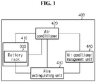
- FIG. 1 is a schematic conceptual diagram showing the elements of an energy storage system according to an embodiment of the present disclosure.
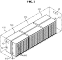
- FIG. 2 is a schematic perspective view of a battery rack and a container according to an embodiment of the present disclosure.
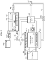
- FIG. 3 is a schematic conceptual diagram showing some elements of the energy storage system according to an embodiment of the present disclosure.
- the energy storage system 400 of the present disclosure includes at least one battery rack 300, a container 410, an air conditioner 420, a fire extinguishing unit 430 and an air conditioner management unit 440.
- the battery rack 300 may include at least two battery modules 200.
- the plurality of battery modules 200 may be arranged in a direction.
- the battery module 200 may include at least one cell assembly (100 in FIG. 4 ).
- the cell assembly 100 may have a plurality of secondary batteries 110 arranged in a direction.
- the secondary battery 110 may be a pouch-type secondary battery 110.
- the cell assembly 100 may include a plurality of pouch-type secondary batteries 110 stacked side by side in the front-rear direction.
- one cell assembly 100 may include 21 pouch-type secondary batteries 110.
- the pouch-type secondary battery 110 may include an electrode assembly (not shown), an electrolyte solution (not shown) and a pouch 116.
- a positive electrode lead 111 and a negative electrode lead 112 may be formed at the left and right ends with respect to the center of the secondary battery 110. That is, the positive electrode lead 111 may be provided at one end (the right end) with the respect to the center of the secondary battery 110. Additionally, the negative electrode lead 112 may be provided at the other end (the left end) with respect to the center of the secondary battery 110.
- the battery module 200 according to the present disclosure is not limited to the pouch-type secondary battery 110 as described above and various types of secondary batteries known at the time of filing the patent application may be employed.
- the container 410 may have an internal space for receiving the at least one battery rack 300.
- the container 410 may have outer walls that form the exterior of the energy storage system 400.
- the container 410 may be a common type of container 410 commonly used to store a product. The details of the container 410 are omitted herein.
- the container 410 may be in the shape of a hollow rectangular box.
- the container 410 has a feeding port K3 at the upper part of each of the front wall and the rear wall to feed the heat exchanger medium.
- the container 410 has a suction port K2 in each of the front wall and the rear wall to suck and discharge the temperature increased heat exchanger medium.
- the air conditioner 420 may include an outside heat exchanger 422 configured to cool a heat exchanger medium in the container 410 when the temperature of the heat exchanger medium rises.
- the outside heat exchanger 422 may function to increase the temperature of the heat exchanger medium.
- the outside heat exchanger 422 may include a high thermal conductivity metal (copper, aluminum, or the like).
- the heat exchanger medium may be, for example, a coolant for industrial use or air.
- the air conditioner 420 may include a circulation path 424 configured to allow the heat exchanger medium to circulate between the container 410 and the outside heat exchanger 422. That is, the circulation path 424 may include an outlet pipe 424b configured to feed the heat exchanger medium cooled in the outside heat exchanger 422 to the container 410 by a fan 427, and an inlet pipe 424a configured to transfer the temperature increased heat exchanger medium in the container 410 to the outside heat exchanger 422.
- the air conditioner 420 may include the fan 427 configured to transfer the heat exchanger medium.
- the fan 427 may be configured to suck the temperature increased heat exchanger medium in the container 410 and transfer it to the outside heat exchanger 422, or feed the heat exchanger medium subjected to heat exchange in the outside heat exchanger 422 into the container 410.
- the fire extinguishing unit 430 may be configured to detect the temperature of the at least one battery module 200 that is equal to or higher than a predetermined temperature or smoke that is generated in the at least one battery module 200 and feed the fire extinguishing agent 433 to the battery module 200.
- the predetermined temperature may be 200°C or more.
- the fire extinguishing unit 430 may include a fire extinguishing agent tank 432 in which a fire extinguishing agent 433 is stored.
- the fire extinguishing agent tank 432 may store the fire extinguishing agent 433 therein.
- the fire extinguishing agent 433 may be an enrichment solution of an inorganic salt such as potassium carbonate, a chemical foam, an air foam, carbon dioxide or water.
- the fire extinguishing agent tank 432 may have compressed gas to spray the fire extinguishing agent 433 or move the fire extinguishing agent 433 along the pipe with the optimal pressure.
- the fire extinguishing agent tank 432 may store the fire extinguishing agent 433 therein.
- the fire extinguishing agent 433 may be, for example, water.
- the fire extinguishing agent tank 432 may have compressed gas to spray the fire extinguishing agent 433 or move the fire extinguishing agent 433 along the pipe with the optimal pressure.
- the air conditioner management unit 440 may be configured to spray the fire extinguishing agent 433 in the fire extinguishing agent tank 432 onto the outer surface of the outside heat exchanger 422.
- the air conditioner management unit 440 may uniformly spray the fire extinguishing agent 433 in the fire extinguishing agent tank 432 onto a cooling part in which heat exchange of the heat exchanger medium of the outside heat exchanger 422 takes place.
- the present disclosure includes the air conditioner management unit 440 configured to spray the fire extinguishing agent 433 in the fire extinguishing agent tank 432 onto the outer surface of the outside heat exchanger 422, thereby increasing the heat exchange efficiency of the outside heat exchanger 422 using the enthalpy of vaporization of the fire extinguishing agent 433 sprayed onto the outside heat exchanger 422. Accordingly, it is possible to apply a small outside heat exchanger 422, thereby increasing the cost competitiveness of the energy storage system.
- frost when frost is formed on the outside heat exchanger 422 in winter time, the frost may be removed by spraying the fire extinguishing agent 433. That is, when frost is formed on the outside heat exchanger 422, the conventional art has removed the frost by operating the cooling cycle of the outside heat exchanger 422 in the contrary direction, and to this end, it was inevitable to stop heating the container 410. In contrast, the present disclosure may remove frost on the outside heat exchanger 422 using the fire extinguishing agent 433 of the fire extinguishing unit without stopping heating the container 410 in winter time, thereby avoiding overcooling the battery rack 300.
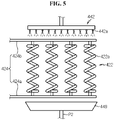
- FIG. 5 is a schematic diagram of a feed header, the outside heat exchanger and a collection plate of the energy storage system according to an embodiment of the present disclosure.
- FIG. 6 is a schematic side view of the feed header of the energy storage system according to an embodiment of the present disclosure.
- FIG. 7 is a schematic cross-sectional view of a spiral pipe of the outside heat exchanger of FIG. 5 .
- the air conditioner management unit 440 may include the feed header 442.
- the feed header 442 may have a plurality of nozzles 442a arranged at a predetermined distance to uniformly spray the fire extinguishing agent 433 onto the outer surface of the outside heat exchanger 422.
- the pair of nozzles 442a may be arranged at the predetermined distance along the lengthwise direction of the feed header 442 below the feed header 442.
- the outside heat exchanger 422 may include the spiral pipe 422a that vertically extends.
- the spiral pipe 422a may be configured to allow the heat exchanger medium to move along the internal space.
- the spiral pipe 422a may have ribs R1 on the outer surface, and the rib R1 may extend linearly along the pipe.
- the rib R1 may extend outwardly.
- the spiral pipe 422a may be configured to allow the fire extinguishing agent 433 fed from the feed header 442 to move down along the space between the ribs R1.
- the air conditioner management unit 440 includes the feed header 442 having the plurality of nozzles 442a arranged at the predetermined distance to uniformly spray the fire extinguishing agent 433 onto the outer surface of the outside heat exchanger 422, and the outside heat exchanger 422 includes the spiral pipe 422a configured to allow the heat exchanger medium to move along the internal space and having, on the outer surface, the ribs R1 linearly extending along the pipe, so the fire extinguishing agent 433 fed from the feed header 442 to the outside heat exchanger 422 does not vanish immediately and moves down along the spiral pipe 422a by the gravitational force, thereby effectively increasing the heat exchange rate between the fire extinguishing agent 433 and the spiral pipe 422a. Accordingly, it is possible to maximize the heat exchange (cooling) efficiency of the outside heat exchanger 422 by the air conditioner management unit 440. Further, it is possible to effectively melt and remove frost formed on the outside heat exchanger 422 in winter time.
- FIG. 8 is a schematic diagram of an outside heat exchanger of the energy storage system according to another embodiment of the present disclosure.
- the outside heat exchanger 422A of the energy storage system may include a tube 422b having a plurality of fins 422b1 instead of the spiral pipe.
- the tube 422b may have one end connected to an outlet pipe 424b configured to feed the cooled heat exchanger medium to the container 410, and the other end connected to an inlet pipe 424a configured to transfer the temperature increased heat exchanger medium in the container 410 to the outside heat exchanger 422A.
- the present disclosure sprays the fire extinguishing agent from the nozzles 442a of the feed header 442 to the plurality of fins 422b 1 and the tube 422b of the outside heat exchanger 422A for the heat exchange between the fire extinguishing agent and the heat exchanger medium, thereby maximizing the cooling efficiency of the heat exchanger.
- the air conditioner management unit 440 may further include a feed pipe P1, a feed pump 446, an active valve 447 and a control unit 448.
- the feed pipe P1 may be configured to connect the outlet of the fire extinguishing agent tank 432 to the inlet of the feed header 442.
- the feed pump 446 may create pressure to feed the fire extinguishing agent 433 to the feed header 442 through the feed pipe P1.
- the active valve 447 may be configured to open and close the feed pipe P1 in response to a signal from the control unit 448.
- the control unit 448 may be configured to control the operation of the active valve 447 and the feed pump 446.
- the active valve 447 may be, for example, a control valve, an electric valve, a solenoid valve or a pneumatic valve.
- the air conditioner management unit 440 may further include a collection plate 449, a return pipe P2, a return valve 447b and a return pump 445.
- the collection plate 449 may be configured to collect the fire extinguishing agent 433 sprayed onto the outside heat exchanger 422.
- the collection plate 449 may be in the form of a bowl having a sufficient size to cover the bottom of the outside heat exchanger 422.
- the return pipe P2 may be a pipe configured to connect the outlet of the collection plate 449 to the inlet of the fire extinguishing agent tank 432.
- the return pipe P2 may provide a movement passage along which the fire extinguishing agent 433 collected in the collection plate 449 moves to the fire extinguishing agent tank 432.
- the return valve 447b may be controlled by the control unit 448 to open or close the return pipe P2.
- the return pump 445 may create pressure to the return pipe P2 to transfer the fire extinguishing agent 433 collected in the collection plate 449 to the fire extinguishing agent tank 432 through the return pipe P2.
- the air conditioner management unit 440 may further include a first temperature sensor S1, a second temperature sensor S2 and a heater 443.
- the first temperature sensor S1 may be configured to measure the temperature of the outside heat exchanger 422.
- the first temperature sensor S1 may be configured to transmit measured temperature information to the control unit 448 using a signal cable.
- the second temperature sensor S2 may be configured to measure the temperature of the fire extinguishing agent 433 in the fire extinguishing agent tank 432.
- the second temperature sensor S2 may be configured to transmit the measured temperature information to the control unit 448 using a signal cable.
- the heater 443 may be configured to heat the fire extinguishing agent 433 in the fire extinguishing agent tank 432. The heater 443 may be powered on/off in response to the signal from the control unit 448.
- the present disclosure further includes the first temperature sensor S1, the second temperature sensor S2 and the heater 443 configured to heat the fire extinguishing agent 433 in the fire extinguishing agent tank 432, so when frost is formed on the outside heat exchanger 422 in winter time, the fire extinguishing agent 433 heated by the heater 443 may be sprayed onto the outside heat exchanger 422. Accordingly, it is possible to remove frost on the outside heat exchanger 422 rapidly.
- the control unit 448 may be configured to open the active valve 447 to operate the feed pump 446. That is, in case that the cooling efficiency above the cooling capacity of the outside heat exchanger 422 is required in summer time, when the temperature of the outside heat exchanger 422 from the first temperature sensor S1 is equal to or higher than the predetermined temperature (40°C), the control unit 448 may open the active valve 447 to operate the feed pump 446 to feed the fire extinguishing agent 433 in the fire extinguishing agent tank 432 to the feed header 442.
- the control unit 448 may open the active valve 447 to operate the feed pump 446 to feed the fire extinguishing agent 433 in the fire extinguishing agent tank 432 to the feed header 442.
- the temperature of the fire extinguishing agent 433 may be increased to about 50°C or higher by the heater 443.
- control unit 448 may be configured to operate the heater 443 to increase the temperature of the fire extinguishing agent 433 in the fire extinguishing agent tank 432.
- the control unit 448 may operate the heater 443 to increase the temperature of the fire extinguishing agent 433 in the fire extinguishing agent tank 432.
- control unit 448 may be configured to operate the heater 443 to increase the temperature of the fire extinguishing agent 433 in the fire extinguishing agent tank 432 when the temperature of the fire extinguishing agent 433 in the fire extinguishing agent tank 432 is equal to or lower than the predetermined temperature, thereby effectively removing frost on the outside heat exchanger 422 in winter time. Further, it is possible to prevent the fire extinguishing agent 433 in the fire extinguishing agent tank 432 from freezing, thereby preventing the failed feeding of the fire extinguishing agent 433 in the event of fires.
- the fire extinguishing agent tank 432 may further include an antifreeze (not shown) that is mixed with the fire extinguishing agent 433.
- the antifreeze may be configured to prevent the fire extinguishing agent 433 from freezing and preserve it in a liquid state at low temperatures.
- the antifreeze may include ethylene glycol or propylene glycol.
- the air conditioner management unit 440 may include a filter 441 disposed in the return pipe P2.
- the filter 441 may be connected to the return pipe P2.
- the filter 441 may be configured to remove contaminants in the collected fire extinguishing agent 433.
- the filter 441 may be configured to remove the contaminants having the size of 10 ⁇ m or more.
- the filter 441 may be configured to filter out the contaminants in the fire extinguishing agent 433 passing through the return pipe P2.
- the air conditioner management unit 440 further includes the filter 441 disposed in the return pipe P2 and configured to remove contaminants in the collected fire extinguishing agent 433, so the contaminants introduced in the process of spraying the fire extinguishing agent 433 onto the outside heat exchanger 422 are removed, thereby avoiding the clogged return pipe P2 or feed pipe P1 due to the contaminants. Accordingly, it is possible to effectively increase the durability of the energy storage system 400.
- the air conditioner management unit 440 may further include an auxiliary tank 432b.
- the auxiliary tank 432b may store an extra fire extinguishing agent 433.
- the auxiliary tank 432b may be configured to replenish the fire extinguishing agent 433.
- the fire extinguishing agent tank 432 may include a measurement sensor (not shown) to measure the water level of the fire extinguishing agent 433.
- the control unit 448 may receive water level information of the fire extinguishing agent 433 in the fire extinguishing agent tank 432 through the measurement sensor.
- the control unit 448 may open an auxiliary valve 432b1 to feed the extra fire extinguishing agent 433 from the auxiliary tank 432b to the fire extinguishing agent tank 432.
- the auxiliary tank 432b and the fire extinguishing agent tank 432 may be connected with an auxiliary pipe 432b2.
- the auxiliary pipe 432b2 may be configured to transfer the extra fire extinguishing agent 433 in the auxiliary tank 432b to the fire extinguishing agent tank 432.
- the battery rack 300 may further include other element such as a Battery Management System (BMS) inside or outside of a rack case 310.
- BMS Battery Management System
- the rack case 310 may be configured to receive the plurality of battery modules 200 in a vertical stack shape.
- the battery module 200 may be mounted in the rack case 310 with the lower surface placed in parallel to the horizon.
- the horizontal direction refers to a direction parallel to the ground when the battery module 200 is placed on the ground, and may be referred to as at least one direction on a plane perpendicular to the vertical direction.
- the rack case 310 may have at least one open side through which the battery module 200 is inserted into the internal space.
- the rack case 310 may be configured to close the open side.
- the energy storage system 400 may include at least two battery racks 300.
- the at least two battery racks 300 may be arranged in a direction.
- the energy storage system 400 may include three battery racks 300 arranged in a direction.
- the energy storage system 400 may include a separate central control unit (not shown) to control the charge and discharge of the three battery racks 300.
- Air conditioner management unit 442 Feed header 442a: Nozzle 422a, 422b: Spiral pipe, Tube R1: Rib PI: Feed pipe 446: Feed pump 447: Active valve 448: Control unit 449: Collection plate P2: Return pipe 445: Return pump S1, S2: First temperature sensor, Second temperature sensor 443: Heater 441: Filter 432b: Auxiliary tank 300: Battery rack 310: Rack case 200: Battery module 100: Cell assembly 110: Secondary battery
Landscapes
- Engineering & Computer Science (AREA)
- Chemical & Material Sciences (AREA)
- General Chemical & Material Sciences (AREA)
- Electrochemistry (AREA)
- Chemical Kinetics & Catalysis (AREA)
- Manufacturing & Machinery (AREA)
- Physics & Mathematics (AREA)
- Mechanical Engineering (AREA)
- General Engineering & Computer Science (AREA)
- Health & Medical Sciences (AREA)
- Emergency Management (AREA)
- Thermal Sciences (AREA)
- Public Health (AREA)
- Business, Economics & Management (AREA)
- Microelectronics & Electronic Packaging (AREA)
- Combustion & Propulsion (AREA)
- Geometry (AREA)
- Fire-Extinguishing By Fire Departments, And Fire-Extinguishing Equipment And Control Thereof (AREA)
- Secondary Cells (AREA)
- Battery Mounting, Suspending (AREA)
- Other Air-Conditioning Systems (AREA)
Abstract
Description
- The present disclosure relates to an energy storage system, and more particularly, to an energy storage system which increases the heat exchange efficiency of an outside heat exchanger and is easy to maintain and manage an air conditioner.
- The present application claims the benefit of
Korean Patent Application No. 10-2020-0018535 filed on February 14, 2020 - Currently, commercially available secondary batteries include nickel-cadmium batteries, nickel-hydrogen batteries, nickel-zinc batteries, lithium secondary batteries and the like, and among them, lithium secondary batteries have little or no memory effect, and thus they are gaining more attention than nickel-based secondary batteries for their advantages that recharging can be done whenever it is convenient, the self-discharge rate is very low and the energy density is high.
- A lithium secondary battery primarily uses a lithium-based oxide and a carbon material for a positive electrode active material and a negative electrode active material respectively. Additionally, the lithium secondary battery includes an electrode assembly including a positive electrode plate and a negative electrode plate respectively coated with the positive electrode active material and the negative electrode active material and a separator interposed between the positive electrode plate and the negative electrode plate, and a packaging or a battery case in which the electrode assembly is received together with an electrolyte solution in an airtight manner.
- Recently, secondary batteries are being widely used in not only small devices such as portable electronic products but also medium- and large-scale devices such as vehicles and energy storage systems (ESSs). For use in medium- and large-scale devices, many secondary batteries are electrically connected to increase the capacity and output. In particular, medium- and large-scale devices use pouch-type secondary batteries since they are easy to stack.
- More recently, with the use as a source of energy and the growing need for high capacity structures, there is an increasing demand for an energy storage system including a plurality of battery racks including a plurality of battery packs including a plurality of secondary batteries, a container configured to store the plurality of battery racks therein, and an air conditioner for cooling the plurality of battery racks.
- Additionally, in the case of the existing air conditioner of the energy storage system, when the outdoor air temperature is very high in summer time, a heat exchanger (a condenser) of the air conditioner installed outside is not effectively cooled, causing a failure or shutdown (stop) of the air conditioner.
- Further, in tropical regions or deserts, the outdoor air temperature is 40°C or higher, and the small outside heat exchanger (condenser) cannot be effectively cooled, and thus they are replaced with a large outside heat exchanger.
- Additionally, in winter time, it is necessary to heat the container in which the battery racks are received inside to prevent the battery packs from being frozen. However, in winter time, frost may form in the heat exchanger mounted in the outside unit, so it is necessary to remove the frost by stopping the internal heating of the container for a while and operating the cooling cycle of the air conditioner in the reverse direction. As a consequence, the heating of the container is stopped for a while, and the plurality of battery packs in the container may be overcooled.
- The present disclosure is designed to solve the above-described problem, and therefore the present disclosure is directed to providing an energy storage system which increases the heat exchange efficiency of an outside heat exchanger and is easy to maintain and manage an air conditioner.
- These and other objects and advantages of the present disclosure may be understood by the following description, and will be apparent from the embodiments of the present disclosure. In addition, it will be readily appreciated that the objects and advantages of the present disclosure may be realized by means and combinations thereof.
- To achieve the above-described object, an energy storage system according to the present disclosure includes at least one battery rack, each battery rack including at least two battery modules, a container in which the at least one battery rack is received, an air conditioner including an outside heat exchanger configured to cool a heat exchanger medium having a temperature rise in the container and a circulation path configured to allow the heat exchanger medium to circulate between the container and the outside heat exchanger, a fire extinguishing unit including a fire extinguishing agent tank in which a fire extinguishing agent is stored inside and configured to detect a temperature of the at least one battery module that is equal to or higher than a predetermined temperature or smoke that is generated in the at least one battery module and feed the fire extinguishing agent to the battery module, and an air conditioner management unit configured to spray the fire extinguishing agent in the fire extinguishing agent tank onto an outer surface of the outside heat exchanger.
- Additionally, the air conditioner management unit may further include a feed header having a plurality of nozzles arranged at a predetermined distance to uniformly spray the fire extinguishing agent onto the outer surface of the outside heat exchanger, and the outside heat exchanger may include a spiral pipe having ribs or a tube having a plurality of fins to allow the heat exchanger medium to move along an internal space, the rib extending linearly along the pipe outwardly from the outer surface.
- Further, the air conditioner management unit may further include a collection plate configured to collect the fire extinguishing agent sprayed onto the outside heat exchanger, a return pipe configured to connect an outlet of the collection plate to an inlet of the fire extinguishing agent tank, and a return pump configured to transfer the fire extinguishing agent collected in the collection plate to the fire extinguishing agent tank through the return pipe.
- Additionally, the air conditioner management unit may further include a filter disposed in the return pipe to remove contaminants in the collected fire extinguishing agent.
- Further, the air conditioner management unit may further include a feed pipe configured to connect an outlet of the fire extinguishing agent tank to an inlet of the feed header, a feed pump configured to feed the fire extinguishing agent to the feed header through the feed pipe, an active valve configured to open and close the feed pipe, and a control unit configured to control the operation of the active valve and the feed pump.
- Additionally, the air conditioner management unit may further include a first temperature sensor configured to measure a temperature of the outside heat exchanger, a second temperature sensor configured to measure a temperature of the fire extinguishing agent in the fire extinguishing agent tank, and a heater configured to heat the fire extinguishing agent in the fire extinguishing agent tank.
- Additionally, the control unit may be configured to open the active valve to operate the feed pump when the temperature of the outside heat exchanger is equal to or higher than a predetermined temperature or is equal to or lower than the predetermined temperature.
- Further, the control unit may be configured to operate the heater to increase the temperature of the fire extinguishing agent in the fire extinguishing agent tank when the temperature of the fire extinguishing agent in the fire extinguishing agent tank is equal to or lower than a predetermined temperature.
- Additionally, the fire extinguishing agent tank may further include an antifreeze that is mixed with the fire extinguishing agent.
- Further, the air conditioner management unit may further include an auxiliary tank configured to store the fire extinguishing agent and replenish the fire extinguishing agent when an amount of the fire extinguishing agent in the fire extinguishing agent tank is equal to or lower than a predetermined amount.
- According to an aspect of the present disclosure, the energy storage system of the present disclosure includes the air conditioner management unit configured to spray the fire extinguishing agent in the fire extinguishing agent tank onto the outer surface of the outside heat exchanger, thereby increasing the heat exchange efficiency of the outside heat exchanger using the enthalpy of vaporization or heat exchange of the fire extinguishing agent sprayed onto the outside heat exchanger. Accordingly, it is possible to apply a small outside heat exchanger, thereby increasing the cost competitiveness of the energy storage system.
- Additionally, according to an aspect of the present disclosure, the air conditioner management unit includes the feed header having the plurality of nozzles arranged at a predetermined distance to uniformly spray the fire extinguishing agent onto the outer surface of the outside heat exchanger, and the outside heat exchanger includes the spiral pipe configured to allow the heat exchanger medium to move along the internal space and having the linearly extended rib on the outer surface, so that the fire extinguishing agent fed from the feed header to the outside heat exchanger does not vanish immediately and moves down along the spiral pipe by the gravitational force, thereby effectively increasing the heat exchange rate between the fire extinguishing agent and the spiral pipe. Accordingly, it is possible to maximize the heat exchange (cooling) efficiency of the outside heat exchanger by the air conditioner management unit. Further, it is possible to effectively melt and remove frost formed on the outside heat exchanger in winter time.
- The accompanying drawings illustrate preferred embodiments of the present disclosure, and together with the following detailed description, serve to provide a further understanding of the technical spirit of the present disclosure. However, the present disclosure is not to be construed as being limited to the drawings.
-
FIG. 1 is a schematic conceptual diagram showing the elements of an energy storage system according to an embodiment of the present disclosure. -
FIG. 2 is a schematic perspective view of a battery rack and a container according to an embodiment of the present disclosure. -
FIG. 3 is a schematic conceptual diagram showing some elements of an energy storage system according to an embodiment of the present disclosure. -
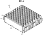
FIG. 4 is a schematic perspective view of a cell assembly of an energy storage system according to an embodiment of the present disclosure. -
FIG. 5 is a schematic diagram of a feed header, an outside heat exchanger and a collection plate of an energy storage system according to an embodiment of the present disclosure. -
FIG. 6 is a schematic side view of a feed header of an energy storage system according to an embodiment of the present disclosure. -
FIG. 7 is a schematic cross-sectional view of a spiral pipe of an outside heat exchanger ofFIG. 5 . -
FIG. 8 is a schematic diagram of an outside heat exchanger of an energy storage system according to another embodiment of the present disclosure. - Hereinafter, the preferred embodiments of the present disclosure will be described in detail with reference to the accompanying drawings. Prior to the description, it should be understood that the terms or words used in the specification and the appended claims should not be construed as being limited to general and dictionary meanings, but rather interpreted based on the meanings and concepts corresponding to the technical aspects of the present disclosure on the basis of the principle that the inventor is allowed to define the terms appropriately for the best explanation.
- Therefore, the embodiments described herein and illustrations shown in the drawings are just a most preferred embodiment of the present disclosure, but not intended to fully describe the technical aspects of the present disclosure, so it should be understood that a variety of other equivalents and modifications could have been made thereto at the time that the application was filed.
-
FIG. 1 is a schematic conceptual diagram showing the elements of an energy storage system according to an embodiment of the present disclosure.FIG. 2 is a schematic perspective view of a battery rack and a container according to an embodiment of the present disclosure.FIG. 3 is a schematic conceptual diagram showing some elements of the energy storage system according to an embodiment of the present disclosure. - Referring to
FIGS. 1 to 3 , theenergy storage system 400 of the present disclosure includes at least onebattery rack 300, acontainer 410, anair conditioner 420, afire extinguishing unit 430 and an airconditioner management unit 440. - Here, the
battery rack 300 may include at least twobattery modules 200. The plurality ofbattery modules 200 may be arranged in a direction. In this instance, thebattery module 200 may include at least one cell assembly (100 inFIG. 4 ). Thecell assembly 100 may have a plurality ofsecondary batteries 110 arranged in a direction. - Additionally, the
secondary battery 110 may be a pouch-typesecondary battery 110. For example, as shown inFIG. 4 , thecell assembly 100 may include a plurality of pouch-typesecondary batteries 110 stacked side by side in the front-rear direction. For example, as shown inFIG. 4 , onecell assembly 100 may include 21 pouch-typesecondary batteries 110. - In particular, the pouch-type
secondary battery 110 may include an electrode assembly (not shown), an electrolyte solution (not shown) and apouch 116. - Further, a
positive electrode lead 111 and anegative electrode lead 112 may be formed at the left and right ends with respect to the center of thesecondary battery 110. That is, thepositive electrode lead 111 may be provided at one end (the right end) with the respect to the center of thesecondary battery 110. Additionally, thenegative electrode lead 112 may be provided at the other end (the left end) with respect to the center of thesecondary battery 110. - However, the
battery module 200 according to the present disclosure is not limited to the pouch-typesecondary battery 110 as described above and various types of secondary batteries known at the time of filing the patent application may be employed. - Meanwhile, the
container 410 may have an internal space for receiving the at least onebattery rack 300. Thecontainer 410 may have outer walls that form the exterior of theenergy storage system 400. For example, thecontainer 410 may be a common type ofcontainer 410 commonly used to store a product. The details of thecontainer 410 are omitted herein. - For example, as shown in
FIG. 2 , thecontainer 410 may be in the shape of a hollow rectangular box. Thecontainer 410 has a feeding port K3 at the upper part of each of the front wall and the rear wall to feed the heat exchanger medium. Additionally, thecontainer 410 has a suction port K2 in each of the front wall and the rear wall to suck and discharge the temperature increased heat exchanger medium. - Further, the
air conditioner 420 may include anoutside heat exchanger 422 configured to cool a heat exchanger medium in thecontainer 410 when the temperature of the heat exchanger medium rises. In addition to the cooling function, theoutside heat exchanger 422 may function to increase the temperature of the heat exchanger medium. For example, theoutside heat exchanger 422 may include a high thermal conductivity metal (copper, aluminum, or the like). Here, the heat exchanger medium may be, for example, a coolant for industrial use or air. - Additionally, the
air conditioner 420 may include acirculation path 424 configured to allow the heat exchanger medium to circulate between thecontainer 410 and theoutside heat exchanger 422. That is, thecirculation path 424 may include anoutlet pipe 424b configured to feed the heat exchanger medium cooled in theoutside heat exchanger 422 to thecontainer 410 by afan 427, and aninlet pipe 424a configured to transfer the temperature increased heat exchanger medium in thecontainer 410 to theoutside heat exchanger 422. - Further, the
air conditioner 420 may include thefan 427 configured to transfer the heat exchanger medium. Thefan 427 may be configured to suck the temperature increased heat exchanger medium in thecontainer 410 and transfer it to theoutside heat exchanger 422, or feed the heat exchanger medium subjected to heat exchange in theoutside heat exchanger 422 into thecontainer 410. - Meanwhile, the
fire extinguishing unit 430 may be configured to detect the temperature of the at least onebattery module 200 that is equal to or higher than a predetermined temperature or smoke that is generated in the at least onebattery module 200 and feed thefire extinguishing agent 433 to thebattery module 200. For example, the predetermined temperature may be 200°C or more. - Additionally, the
fire extinguishing unit 430 may include a fire extinguishingagent tank 432 in which afire extinguishing agent 433 is stored. The fire extinguishingagent tank 432 may store thefire extinguishing agent 433 therein. For example, thefire extinguishing agent 433 may be an enrichment solution of an inorganic salt such as potassium carbonate, a chemical foam, an air foam, carbon dioxide or water. Additionally, the fire extinguishingagent tank 432 may have compressed gas to spray thefire extinguishing agent 433 or move thefire extinguishing agent 433 along the pipe with the optimal pressure. - Further, the fire extinguishing
agent tank 432 may store thefire extinguishing agent 433 therein. For example, thefire extinguishing agent 433 may be, for example, water. Additionally, the fire extinguishingagent tank 432 may have compressed gas to spray thefire extinguishing agent 433 or move thefire extinguishing agent 433 along the pipe with the optimal pressure. - Meanwhile, the air
conditioner management unit 440 may be configured to spray thefire extinguishing agent 433 in the fire extinguishingagent tank 432 onto the outer surface of theoutside heat exchanger 422. The airconditioner management unit 440 may uniformly spray thefire extinguishing agent 433 in the fire extinguishingagent tank 432 onto a cooling part in which heat exchange of the heat exchanger medium of theoutside heat exchanger 422 takes place. - According to this configuration of the present disclosure, the present disclosure includes the air
conditioner management unit 440 configured to spray thefire extinguishing agent 433 in the fire extinguishingagent tank 432 onto the outer surface of theoutside heat exchanger 422, thereby increasing the heat exchange efficiency of theoutside heat exchanger 422 using the enthalpy of vaporization of thefire extinguishing agent 433 sprayed onto theoutside heat exchanger 422. Accordingly, it is possible to apply a smalloutside heat exchanger 422, thereby increasing the cost competitiveness of the energy storage system. - Further, when frost is formed on the
outside heat exchanger 422 in winter time, the frost may be removed by spraying thefire extinguishing agent 433. That is, when frost is formed on theoutside heat exchanger 422, the conventional art has removed the frost by operating the cooling cycle of theoutside heat exchanger 422 in the contrary direction, and to this end, it was inevitable to stop heating thecontainer 410. In contrast, the present disclosure may remove frost on theoutside heat exchanger 422 using thefire extinguishing agent 433 of the fire extinguishing unit without stopping heating thecontainer 410 in winter time, thereby avoiding overcooling thebattery rack 300. -
FIG. 5 is a schematic diagram of a feed header, the outside heat exchanger and a collection plate of the energy storage system according to an embodiment of the present disclosure.FIG. 6 is a schematic side view of the feed header of the energy storage system according to an embodiment of the present disclosure. Additionally,FIG. 7 is a schematic cross-sectional view of a spiral pipe of the outside heat exchanger ofFIG. 5 . - Referring to
FIGS. 5 to 7 together withFIG. 3 , the airconditioner management unit 440 may include thefeed header 442. Thefeed header 442 may have a plurality ofnozzles 442a arranged at a predetermined distance to uniformly spray thefire extinguishing agent 433 onto the outer surface of theoutside heat exchanger 422. For example, as shown inFIG. 6 , the pair ofnozzles 442a may be arranged at the predetermined distance along the lengthwise direction of thefeed header 442 below thefeed header 442. - Additionally, the
outside heat exchanger 422 may include thespiral pipe 422a that vertically extends. Thespiral pipe 422a may be configured to allow the heat exchanger medium to move along the internal space. For example, as shown inFIG. 7 , thespiral pipe 422a may have ribs R1 on the outer surface, and the rib R1 may extend linearly along the pipe. The rib R1 may extend outwardly. Thespiral pipe 422a may be configured to allow thefire extinguishing agent 433 fed from thefeed header 442 to move down along the space between the ribs R1. - According to this configuration of the present disclosure, the air
conditioner management unit 440 includes thefeed header 442 having the plurality ofnozzles 442a arranged at the predetermined distance to uniformly spray thefire extinguishing agent 433 onto the outer surface of theoutside heat exchanger 422, and theoutside heat exchanger 422 includes thespiral pipe 422a configured to allow the heat exchanger medium to move along the internal space and having, on the outer surface, the ribs R1 linearly extending along the pipe, so thefire extinguishing agent 433 fed from thefeed header 442 to theoutside heat exchanger 422 does not vanish immediately and moves down along thespiral pipe 422a by the gravitational force, thereby effectively increasing the heat exchange rate between thefire extinguishing agent 433 and thespiral pipe 422a. Accordingly, it is possible to maximize the heat exchange (cooling) efficiency of theoutside heat exchanger 422 by the airconditioner management unit 440. Further, it is possible to effectively melt and remove frost formed on theoutside heat exchanger 422 in winter time. -
FIG. 8 is a schematic diagram of an outside heat exchanger of the energy storage system according to another embodiment of the present disclosure. - Referring to
FIG. 8 , when compared with theoutside heat exchanger 422 ofFIG. 5 , theoutside heat exchanger 422A of the energy storage system according to another embodiment of the present disclosure may include atube 422b having a plurality of fins 422b1 instead of the spiral pipe. - In detail, the
tube 422b may have one end connected to anoutlet pipe 424b configured to feed the cooled heat exchanger medium to thecontainer 410, and the other end connected to aninlet pipe 424a configured to transfer the temperature increased heat exchanger medium in thecontainer 410 to theoutside heat exchanger 422A. - According to this configuration of the present disclosure, the present disclosure sprays the fire extinguishing agent from the
nozzles 442a of thefeed header 442 to the plurality offins 422b 1 and thetube 422b of theoutside heat exchanger 422A for the heat exchange between the fire extinguishing agent and the heat exchanger medium, thereby maximizing the cooling efficiency of the heat exchanger. - Referring back to
FIG. 3 , the airconditioner management unit 440 may further include a feed pipe P1, afeed pump 446, anactive valve 447 and acontrol unit 448. The feed pipe P1 may be configured to connect the outlet of the fire extinguishingagent tank 432 to the inlet of thefeed header 442. Thefeed pump 446 may create pressure to feed thefire extinguishing agent 433 to thefeed header 442 through the feed pipe P1. Theactive valve 447 may be configured to open and close the feed pipe P1 in response to a signal from thecontrol unit 448. Thecontrol unit 448 may be configured to control the operation of theactive valve 447 and thefeed pump 446. Theactive valve 447 may be, for example, a control valve, an electric valve, a solenoid valve or a pneumatic valve. - Additionally, the air
conditioner management unit 440 may further include acollection plate 449, a return pipe P2, areturn valve 447b and areturn pump 445. Thecollection plate 449 may be configured to collect thefire extinguishing agent 433 sprayed onto theoutside heat exchanger 422. Thecollection plate 449 may be in the form of a bowl having a sufficient size to cover the bottom of theoutside heat exchanger 422. - Further, the return pipe P2 may be a pipe configured to connect the outlet of the
collection plate 449 to the inlet of the fire extinguishingagent tank 432. The return pipe P2 may provide a movement passage along which thefire extinguishing agent 433 collected in thecollection plate 449 moves to the fire extinguishingagent tank 432. Thereturn valve 447b may be controlled by thecontrol unit 448 to open or close the return pipe P2. Thereturn pump 445 may create pressure to the return pipe P2 to transfer thefire extinguishing agent 433 collected in thecollection plate 449 to the fire extinguishingagent tank 432 through the return pipe P2. - Additionally, the air
conditioner management unit 440 may further include a first temperature sensor S1, a second temperature sensor S2 and aheater 443. In detail, the first temperature sensor S1 may be configured to measure the temperature of theoutside heat exchanger 422. The first temperature sensor S1 may be configured to transmit measured temperature information to thecontrol unit 448 using a signal cable. The second temperature sensor S2 may be configured to measure the temperature of thefire extinguishing agent 433 in the fire extinguishingagent tank 432. - Further, the second temperature sensor S2 may be configured to transmit the measured temperature information to the
control unit 448 using a signal cable. Theheater 443 may be configured to heat thefire extinguishing agent 433 in the fire extinguishingagent tank 432. Theheater 443 may be powered on/off in response to the signal from thecontrol unit 448. - According to this configuration of the present disclosure, the present disclosure further includes the first temperature sensor S1, the second temperature sensor S2 and the
heater 443 configured to heat thefire extinguishing agent 433 in the fire extinguishingagent tank 432, so when frost is formed on theoutside heat exchanger 422 in winter time, thefire extinguishing agent 433 heated by theheater 443 may be sprayed onto theoutside heat exchanger 422. Accordingly, it is possible to remove frost on theoutside heat exchanger 422 rapidly. - When the temperature of the
outside heat exchanger 422 is equal to or higher than a predetermined temperature, thecontrol unit 448 may be configured to open theactive valve 447 to operate thefeed pump 446. That is, in case that the cooling efficiency above the cooling capacity of theoutside heat exchanger 422 is required in summer time, when the temperature of theoutside heat exchanger 422 from the first temperature sensor S1 is equal to or higher than the predetermined temperature (40°C), thecontrol unit 448 may open theactive valve 447 to operate thefeed pump 446 to feed thefire extinguishing agent 433 in the fire extinguishingagent tank 432 to thefeed header 442. - To the contrary, when the temperature of the
outside heat exchanger 422 is equal to or lower than the predetermined temperature (-10°C), thecontrol unit 448 may open theactive valve 447 to operate thefeed pump 446 to feed thefire extinguishing agent 433 in the fire extinguishingagent tank 432 to thefeed header 442. In this instance, the temperature of thefire extinguishing agent 433 may be increased to about 50°C or higher by theheater 443. - Additionally, when the temperature of the
fire extinguishing agent 433 in the fire extinguishingagent tank 432 is equal to or lower than the predetermined temperature, thecontrol unit 448 may be configured to operate theheater 443 to increase the temperature of thefire extinguishing agent 433 in the fire extinguishingagent tank 432. That is, in case that the energy storage system is installed in winter time or microthermal climate zone, when the temperature of thefire extinguishing agent 433 in the fire extinguishingagent tank 432 received from the second temperature sensor S2 is equal to or lower than the predetermined temperature (for example, 0°C), thecontrol unit 448 may operate theheater 443 to increase the temperature of thefire extinguishing agent 433 in the fire extinguishingagent tank 432. - According to this configuration of the present disclosure, the present disclosure, the
control unit 448 may be configured to operate theheater 443 to increase the temperature of thefire extinguishing agent 433 in the fire extinguishingagent tank 432 when the temperature of thefire extinguishing agent 433 in the fire extinguishingagent tank 432 is equal to or lower than the predetermined temperature, thereby effectively removing frost on theoutside heat exchanger 422 in winter time. Further, it is possible to prevent thefire extinguishing agent 433 in the fire extinguishingagent tank 432 from freezing, thereby preventing the failed feeding of thefire extinguishing agent 433 in the event of fires. - Further, the fire extinguishing
agent tank 432 may further include an antifreeze (not shown) that is mixed with thefire extinguishing agent 433. The antifreeze may be configured to prevent thefire extinguishing agent 433 from freezing and preserve it in a liquid state at low temperatures. For example, the antifreeze may include ethylene glycol or propylene glycol. - Additionally, the air
conditioner management unit 440 may include afilter 441 disposed in the return pipe P2. Thefilter 441 may be connected to the return pipe P2. Thefilter 441 may be configured to remove contaminants in the collectedfire extinguishing agent 433. Thefilter 441 may be configured to remove the contaminants having the size of 10µm or more. Thefilter 441 may be configured to filter out the contaminants in thefire extinguishing agent 433 passing through the return pipe P2. - According to this configuration of the present disclosure, the air
conditioner management unit 440 further includes thefilter 441 disposed in the return pipe P2 and configured to remove contaminants in the collectedfire extinguishing agent 433, so the contaminants introduced in the process of spraying thefire extinguishing agent 433 onto theoutside heat exchanger 422 are removed, thereby avoiding the clogged return pipe P2 or feed pipe P1 due to the contaminants. Accordingly, it is possible to effectively increase the durability of theenergy storage system 400. - Referring back to
FIG. 3 , the airconditioner management unit 440 may further include anauxiliary tank 432b. Theauxiliary tank 432b may store an extrafire extinguishing agent 433. When the amount of thefire extinguishing agent 433 in the fire extinguishingagent tank 432 is equal to or lower than a predetermined amount, theauxiliary tank 432b may be configured to replenish thefire extinguishing agent 433. - Further, the fire extinguishing
agent tank 432 may include a measurement sensor (not shown) to measure the water level of thefire extinguishing agent 433. Thecontrol unit 448 may receive water level information of thefire extinguishing agent 433 in the fire extinguishingagent tank 432 through the measurement sensor. When the water level of thefire extinguishing agent 433 in the fire extinguishingagent tank 432 is equal to or lower than a predetermined water level, thecontrol unit 448 may open an auxiliary valve 432b1 to feed the extrafire extinguishing agent 433 from theauxiliary tank 432b to the fire extinguishingagent tank 432. Theauxiliary tank 432b and the fire extinguishingagent tank 432 may be connected with an auxiliary pipe 432b2. The auxiliary pipe 432b2 may be configured to transfer the extrafire extinguishing agent 433 in theauxiliary tank 432b to the fire extinguishingagent tank 432. - Referring back to
FIG. 2 , thebattery rack 300 may further include other element such as a Battery Management System (BMS) inside or outside of arack case 310. - Additionally, the
rack case 310 may be configured to receive the plurality ofbattery modules 200 in a vertical stack shape. Thebattery module 200 may be mounted in therack case 310 with the lower surface placed in parallel to the horizon. - Here, the horizontal direction refers to a direction parallel to the ground when the
battery module 200 is placed on the ground, and may be referred to as at least one direction on a plane perpendicular to the vertical direction. - Further, the
rack case 310 may have at least one open side through which thebattery module 200 is inserted into the internal space. Therack case 310 may be configured to close the open side. - Meanwhile, the
energy storage system 400 according to an embodiment of the present disclosure may include at least two battery racks 300. The at least twobattery racks 300 may be arranged in a direction. For example, as shown inFIG. 2 , theenergy storage system 400 may include threebattery racks 300 arranged in a direction. Additionally, theenergy storage system 400 may include a separate central control unit (not shown) to control the charge and discharge of the threebattery racks 300. - The terms indicating directions as used herein such as upper, lower, left, right, front and rear are used for convenience of description only, and it is obvious to those skilled in the art that the term may change depending on the position of the stated element or an observer.
- While the present disclosure has been hereinabove described with regard to a limited number of embodiments and drawings, the present disclosure is not limited thereto and it is obvious to those skilled in the art that various modifications and changes may be made thereto within the technical aspects of the present disclosure and the equivalent scope of the appended claims.
-
400: Energy storage system 410: Container 420: Air conditioner 422: Outside heat exchanger 424: Circulation path 430: Fire extinguishing unit 432: Fire extinguishing agent tank 433: Fire extinguishing agent 440: Air conditioner management unit 442: Feed header 442a: Nozzle 422a, 422b: Spiral pipe, Tube R1: Rib PI: Feed pipe 446: Feed pump 447: Active valve 448: Control unit 449: Collection plate P2: Return pipe 445: Return pump S1, S2: First temperature sensor, Second temperature sensor 443: Heater 441: Filter 432b: Auxiliary tank 300: Battery rack 310: Rack case 200: Battery module 100: Cell assembly 110: Secondary battery
Claims (10)
- An energy storage system, comprising:at least one battery rack, each battery rack including at least two battery modules;a container in which the at least one battery rack is received;an air conditioner including an outside heat exchanger configured to cool a heat exchanger medium having a temperature rise in the container, and a circulation path configured to allow the heat exchanger medium to circulate between the container and the outside heat exchanger;a fire extinguishing unit including a fire extinguishing agent tank in which a fire extinguishing agent is stored inside, and configured to detect a temperature of the at least one battery module that is equal to or higher than a predetermined temperature or smoke that is generated in the at least one battery module and feed the fire extinguishing agent to the battery module; andan air conditioner management unit configured to spray the fire extinguishing agent in the fire extinguishing agent tank onto an outer surface of the outside heat exchanger.
- The energy storage system according to claim 1, wherein the air conditioner management unit includes a feed header having a plurality of nozzles arranged at a predetermined distance to uniformly spray the fire extinguishing agent onto the outer surface of the outside heat exchanger, and
the outside heat exchanger includes a spiral pipe having ribs or a tube having a plurality of fins to allow the heat exchanger medium to move along an internal space, the rib extending linearly along the pipe outwardly from the outer surface. - The energy storage system according to claim 2, wherein the air conditioner management unit further includes:a collection plate configured to collect the fire extinguishing agent sprayed onto the outside heat exchanger;a return pipe configured to connect an outlet of the collection plate to an inlet of the fire extinguishing agent tank; anda return pump configured to transfer the fire extinguishing agent collected in the collection plate to the fire extinguishing agent tank through the return pipe.
- The energy storage system according to claim 3, wherein the air conditioner management unit further includes a filter disposed in the return pipe to remove contaminants in the collected fire extinguishing agent.
- The energy storage system according to claim 2, wherein the air conditioner management unit further includes:a feed pipe configured to connect an outlet of the fire extinguishing agent tank to an inlet of the feed header;a feed pump configured to feed the fire extinguishing agent to the feed header through the feed pipe;an active valve configured to open and close the feed pipe; anda control unit configured to control the operation of the active valve and the feed pump.
- The energy storage system according to claim 5, wherein the air conditioner management unit further includes:a first temperature sensor configured to measure a temperature of the outside heat exchanger;a second temperature sensor configured to measure a temperature of the fire extinguishing agent in the fire extinguishing agent tank; anda heater configured to heat the fire extinguishing agent in the fire extinguishing agent tank.
- The energy storage system according to claim 6, wherein the control unit is configured to open the active valve to operate the feed pump when the temperature of the outside heat exchanger is equal to or higher than a predetermined temperature or is equal to or lower than the predetermined temperature.
- The energy storage system according to claim 7, wherein the control unit is configured to operate the heater to increase the temperature of the fire extinguishing agent in the fire extinguishing agent tank when the temperature of the fire extinguishing agent in the fire extinguishing agent tank is equal to or lower than a predetermined temperature.
- The energy storage system according to claim 1, wherein the fire extinguishing agent tank further includes an antifreeze that is mixed with the fire extinguishing agent.
- The energy storage system according to claim 1, wherein the air conditioner management unit further includes an auxiliary tank configured to store the fire extinguishing agent and replenish the fire extinguishing agent when an amount of the fire extinguishing agent in the fire extinguishing agent tank is equal to or lower than a predetermined amount.
Applications Claiming Priority (2)
| Application Number | Priority Date | Filing Date | Title |
|---|---|---|---|
| KR1020200018535A KR102742697B1 (en) | 2020-02-14 | 2020-02-14 | Energy Storage System |
| PCT/KR2021/095009 WO2021162538A1 (en) | 2020-02-14 | 2021-01-20 | Power storage system |
Publications (3)
| Publication Number | Publication Date |
|---|---|
| EP3989339A1 true EP3989339A1 (en) | 2022-04-27 |
| EP3989339A4 EP3989339A4 (en) | 2022-10-12 |
| EP3989339B1 EP3989339B1 (en) | 2023-11-15 |
Family
ID=77292777
Family Applications (1)
| Application Number | Title | Priority Date | Filing Date |
|---|---|---|---|
| EP21753457.7A Active EP3989339B1 (en) | 2020-02-14 | 2021-01-20 | Energy storage system |
Country Status (9)
| Country | Link |
|---|---|
| US (1) | US12334531B2 (en) |
| EP (1) | EP3989339B1 (en) |
| JP (1) | JP7258218B2 (en) |
| KR (1) | KR102742697B1 (en) |
| CN (1) | CN114342157B (en) |
| ES (1) | ES2963684T3 (en) |
| HU (1) | HUE064195T2 (en) |
| PL (1) | PL3989339T3 (en) |
| WO (1) | WO2021162538A1 (en) |
Cited By (1)
| Publication number | Priority date | Publication date | Assignee | Title |
|---|---|---|---|---|
| CN115957464A (en) * | 2022-12-21 | 2023-04-14 | 中国矿业大学 | Lithium battery cooling and fire extinguishing system and method for energy storage power station |
Families Citing this family (14)
| Publication number | Priority date | Publication date | Assignee | Title |
|---|---|---|---|---|
| KR102289709B1 (en) * | 2020-10-19 | 2021-08-13 | 퍼스트 유한회사 | Fire extinguishing system of battery loading of electric propulsion ship |
| US12199259B1 (en) | 2021-07-14 | 2025-01-14 | Nier Engineering, LLC | Housing as added outer layers with medium circulation |
| KR102679229B1 (en) * | 2022-01-19 | 2024-06-26 | 주식회사 엘지에너지솔루션 | Apparatus and method for fire monitoring |
| KR102452775B1 (en) * | 2022-02-28 | 2022-10-11 | (주)안국엔지니어링 | Fire Suppression System for Battery with Function of Cool Down Fire Extinguishing Agent |
| KR102426579B1 (en) * | 2022-02-28 | 2022-08-01 | (주)에코프로머티리얼즈 | Discharge system of medium-large wasted battery |
| KR102450852B1 (en) * | 2022-04-29 | 2022-10-07 | (주)에코프로머티리얼즈 | Shredding system for eco-friendly recycling of wasted battery |
| US20250030141A1 (en) * | 2022-05-02 | 2025-01-23 | Lg Energy Solution, Ltd. | Energy storage system |
| KR102512096B1 (en) * | 2022-09-02 | 2023-03-20 | 에스아이에스 주식회사 | Dismantling system of spent lithium ion battery pack |
| CN115663308B (en) * | 2022-10-31 | 2023-09-01 | 徐州百事利电动车业有限公司 | Fire alarm method and device for storage battery |
| US20240162560A1 (en) * | 2022-11-15 | 2024-05-16 | Enphase Energy, Inc. | Storage system configured for use with an energy management system |
| CN116907027A (en) * | 2023-06-02 | 2023-10-20 | 江西浩金欧博环境科技有限公司 | Heat exchanger protection device using environment-friendly refrigerant, air conditioning unit and fire extinguishing method of air conditioning unit |
| CN116387694A (en) * | 2023-06-02 | 2023-07-04 | 深圳市首航新能源股份有限公司 | Temperature control system |
| CN117599370A (en) * | 2023-10-24 | 2024-02-27 | 北京美力马消防设备有限公司 | Energy storage battery fire protection system |
| CN117913447B (en) * | 2023-12-07 | 2024-11-29 | 南京普瑞泰格安全设备工程有限公司 | An explosion-proof battery for a portable test bench |
Family Cites Families (26)
| Publication number | Priority date | Publication date | Assignee | Title |
|---|---|---|---|---|
| JPH0316520Y2 (en) | 1987-05-13 | 1991-04-09 | ||
| KR20030043033A (en) | 2001-11-26 | 2003-06-02 | 주식회사 엘지이아이 | Cooling apparatus and method of heat exchanger for split air conditioner |
| KR200321073Y1 (en) | 2003-04-08 | 2003-07-22 | 표안설 | Air conditioning system |
| JP4436223B2 (en) | 2004-10-07 | 2010-03-24 | 三菱重工業株式会社 | Air conditioner and operation method thereof |
| KR100778435B1 (en) * | 2005-07-05 | 2007-11-21 | 삼성에스디아이 주식회사 | Battery module fire extinguishing system |
| KR200398404Y1 (en) | 2005-07-06 | 2005-10-12 | 주식회사 에이알 | Water Spray Device on the Air Cooling Type Condenser |
| KR200445599Y1 (en) | 2009-05-20 | 2009-08-19 | 정민수 | Fusiform outdoor condenser |
| KR20120109152A (en) | 2011-03-28 | 2012-10-08 | 엘지전자 주식회사 | Outdoor unit for an air conditioner and a control method the same |
| CN202737006U (en) * | 2012-08-15 | 2013-02-13 | 北京汽车新能源汽车有限公司 | Air conditioner battery box for electric vehicle |
| JP6297922B2 (en) * | 2014-05-23 | 2018-03-20 | 株式会社デンソー | Battery pack |
| KR101652975B1 (en) * | 2014-08-28 | 2016-09-12 | (주)오렌지파워 | An energy storage system |
| JP2016067642A (en) * | 2014-09-30 | 2016-05-09 | 三菱重工業株式会社 | Electrical storage device firefighting equipment, electrical storage device and electrical storage device firefighting method |
| JP2017147128A (en) * | 2016-02-17 | 2017-08-24 | 三菱重工業株式会社 | Battery module and battery system |
| CN106816668A (en) | 2017-03-22 | 2017-06-09 | 北京航盛新能科技有限公司 | A kind of electrokinetic cell thermal runaway cooling fire extinguishing liquid cooling apparatus, monitoring system and method |
| CN207407546U (en) * | 2017-08-15 | 2018-05-25 | 聊城大学 | A kind of air-conditioning incubator |
| JP2019043385A (en) * | 2017-09-04 | 2019-03-22 | 株式会社デンソー | Water spray cooler |
| JP6930357B2 (en) | 2017-10-13 | 2021-09-01 | 株式会社デンソー | Battery cooling system |
| US20200400354A1 (en) | 2018-04-11 | 2020-12-24 | Mitsubishi Electric Corporation | Air-conditioning apparatus |
| KR102050803B1 (en) * | 2019-03-14 | 2019-12-04 | 주식회사 창성에이스산업 | Automatic Fire Extinguishing System To prevent Fire Sensing and Explosion Of Energy Storage Device |
| CN110165110A (en) | 2019-05-08 | 2019-08-23 | 国网电力科学研究院武汉南瑞有限责任公司 | Lithium battery energy storage battery container and its fire prevention partition method with fire prevention isolation features |
| KR102021072B1 (en) | 2019-05-15 | 2019-11-05 | 주식회사 아산정밀 | Fire protection system for energy storage system |
| CN110360769B (en) | 2019-08-06 | 2023-11-07 | 浙江英特科技股份有限公司 | Heat pump system with phase-change energy tower and heat exchange method thereof |
| CN110578766A (en) | 2019-09-11 | 2019-12-17 | 华南理工大学 | An electromagnetic active vibration absorber |
| CN110576766B (en) * | 2019-09-12 | 2021-02-19 | 北京经纬恒润科技股份有限公司 | Vehicle heat exchange system |
| CN110701731A (en) * | 2019-11-14 | 2020-01-17 | 宁波奥克斯电气股份有限公司 | Air conditioner defrosting system, air conditioner defrosting method and air conditioner |
| KR102156625B1 (en) | 2020-02-11 | 2020-09-17 | 삼성디스플레이 주식회사 | Display module |
-
2020
- 2020-02-14 KR KR1020200018535A patent/KR102742697B1/en active Active
-
2021
- 2021-01-20 CN CN202180005116.2A patent/CN114342157B/en active Active
- 2021-01-20 WO PCT/KR2021/095009 patent/WO2021162538A1/en not_active Ceased
- 2021-01-20 ES ES21753457T patent/ES2963684T3/en active Active
- 2021-01-20 JP JP2022505498A patent/JP7258218B2/en active Active
- 2021-01-20 EP EP21753457.7A patent/EP3989339B1/en active Active
- 2021-01-20 PL PL21753457.7T patent/PL3989339T3/en unknown
- 2021-01-20 US US17/767,163 patent/US12334531B2/en active Active
- 2021-01-20 HU HUE21753457A patent/HUE064195T2/en unknown
Cited By (1)
| Publication number | Priority date | Publication date | Assignee | Title |
|---|---|---|---|---|
| CN115957464A (en) * | 2022-12-21 | 2023-04-14 | 中国矿业大学 | Lithium battery cooling and fire extinguishing system and method for energy storage power station |
Also Published As
| Publication number | Publication date |
|---|---|
| PL3989339T3 (en) | 2024-02-26 |
| JP7258218B2 (en) | 2023-04-14 |
| KR102742697B1 (en) | 2024-12-13 |
| US12334531B2 (en) | 2025-06-17 |
| HUE064195T2 (en) | 2024-02-28 |
| CN114342157A (en) | 2022-04-12 |
| US20220367944A1 (en) | 2022-11-17 |
| WO2021162538A1 (en) | 2021-08-19 |
| EP3989339A4 (en) | 2022-10-12 |
| JP2022542179A (en) | 2022-09-29 |
| KR20210104217A (en) | 2021-08-25 |
| EP3989339B1 (en) | 2023-11-15 |
| CN114342157B (en) | 2024-10-01 |
| ES2963684T3 (en) | 2024-04-01 |
Similar Documents
| Publication | Publication Date | Title |
|---|---|---|
| EP3989339B1 (en) | Energy storage system | |
| KR101778666B1 (en) | Energy Storage Apparatus of Combined Cooling Manner | |
| EP4024581B1 (en) | Battery rack and energy storage system comprising the same | |
| US9461344B2 (en) | Battery pack container and apparatus for cooling power storage battery pack using the same | |
| CN107431157B (en) | battery module | |
| CN107408650B (en) | Cell cover for secondary battery and battery module including the same | |
| US20080248379A1 (en) | Battery unit | |
| CN101621142A (en) | Cooling frame of cylindrical battery module and cylindrical battery packet | |
| KR20120076752A (en) | Battery pack that inset and outlet are vertical structure | |
| KR101515114B1 (en) | Battery Pack Using Perfluorinated Solution as Coolant | |
| KR102529969B1 (en) | Electric energy storage module with improved cooling efficiency | |
| CN119275407A (en) | Cold Plate | |
| EP4685081A1 (en) | Container module | |
| CN223712831U (en) | Thermal management system, energy storage device and electric equipment | |
| AU2021231265B2 (en) | Battery rack and energy storage system comprising the same | |
| KR101658974B1 (en) | Pack housing and battery pack including the same | |
| KR101593121B1 (en) | Battery module and battery pack including the same | |
| CN218241983U (en) | A battery pack and battery energy storage system | |
| US20250332961A1 (en) | Vehicle | |
| CN220106656U (en) | Energy storage container and energy storage equipment | |
| CN221262519U (en) | Battery, power utilization device and energy storage device | |
| KR101338248B1 (en) | Battery Pack Comprising Cooling System | |
| CN121335819A (en) | Energy storage system | |
| CN120435792A (en) | Container Module | |
| KR20160121941A (en) | Battery module and battery pack including the same |
Legal Events
| Date | Code | Title | Description |
|---|---|---|---|
| STAA | Information on the status of an ep patent application or granted ep patent |
Free format text: STATUS: THE INTERNATIONAL PUBLICATION HAS BEEN MADE |
|
| PUAI | Public reference made under article 153(3) epc to a published international application that has entered the european phase |
Free format text: ORIGINAL CODE: 0009012 |
|
| STAA | Information on the status of an ep patent application or granted ep patent |
Free format text: STATUS: REQUEST FOR EXAMINATION WAS MADE |
|
| 17P | Request for examination filed |
Effective date: 20220121 |
|
| AK | Designated contracting states |
Kind code of ref document: A1 Designated state(s): AL AT BE BG CH CY CZ DE DK EE ES FI FR GB GR HR HU IE IS IT LI LT LU LV MC MK MT NL NO PL PT RO RS SE SI SK SM TR |
|
| A4 | Supplementary search report drawn up and despatched |
Effective date: 20220912 |
|
| RIC1 | Information provided on ipc code assigned before grant |
Ipc: F28F 1/18 20060101ALI20220906BHEP Ipc: F28D 1/047 20060101ALI20220906BHEP Ipc: A62C 35/68 20060101ALI20220906BHEP Ipc: A62C 37/46 20060101ALI20220906BHEP Ipc: A62C 37/40 20060101ALI20220906BHEP Ipc: A62C 3/16 20060101ALI20220906BHEP Ipc: H01M 10/613 20140101ALI20220906BHEP Ipc: H01M 10/627 20140101ALI20220906BHEP Ipc: F28F 13/00 20060101ALI20220906BHEP Ipc: H01M 10/663 20140101AFI20220906BHEP |
|
| DAV | Request for validation of the european patent (deleted) | ||
| DAX | Request for extension of the european patent (deleted) | ||
| GRAP | Despatch of communication of intention to grant a patent |
Free format text: ORIGINAL CODE: EPIDOSNIGR1 |
|
| STAA | Information on the status of an ep patent application or granted ep patent |
Free format text: STATUS: GRANT OF PATENT IS INTENDED |
|
| INTG | Intention to grant announced |
Effective date: 20230719 |
|
| P01 | Opt-out of the competence of the unified patent court (upc) registered |
Effective date: 20230801 |
|
| GRAS | Grant fee paid |
Free format text: ORIGINAL CODE: EPIDOSNIGR3 |
|
| GRAA | (expected) grant |
Free format text: ORIGINAL CODE: 0009210 |
|
| STAA | Information on the status of an ep patent application or granted ep patent |
Free format text: STATUS: THE PATENT HAS BEEN GRANTED |
|
| AK | Designated contracting states |
Kind code of ref document: B1 Designated state(s): AL AT BE BG CH CY CZ DE DK EE ES FI FR GB GR HR HU IE IS IT LI LT LU LV MC MK MT NL NO PL PT RO RS SE SI SK SM TR |
|
| REG | Reference to a national code |
Ref country code: CH Ref legal event code: EP Ref country code: GB Ref legal event code: FG4D |
|
| REG | Reference to a national code |
Ref country code: DE Ref legal event code: R096 Ref document number: 602021006898 Country of ref document: DE |
|
| REG | Reference to a national code |
Ref country code: IE Ref legal event code: FG4D |
|
| REG | Reference to a national code |
Ref country code: SE Ref legal event code: TRGR |
|
| REG | Reference to a national code |
Ref country code: HU Ref legal event code: AG4A Ref document number: E064195 Country of ref document: HU |
|
| REG | Reference to a national code |
Ref country code: LT Ref legal event code: MG9D |
|
| REG | Reference to a national code |
Ref country code: NL Ref legal event code: MP Effective date: 20231115 |
|
| REG | Reference to a national code |
Ref country code: ES Ref legal event code: FG2A Ref document number: 2963684 Country of ref document: ES Kind code of ref document: T3 Effective date: 20240401 |
|
| PG25 | Lapsed in a contracting state [announced via postgrant information from national office to epo] |
Ref country code: GR Free format text: LAPSE BECAUSE OF FAILURE TO SUBMIT A TRANSLATION OF THE DESCRIPTION OR TO PAY THE FEE WITHIN THE PRESCRIBED TIME-LIMIT Effective date: 20240216 |
|
| PG25 | Lapsed in a contracting state [announced via postgrant information from national office to epo] |
Ref country code: IS Free format text: LAPSE BECAUSE OF FAILURE TO SUBMIT A TRANSLATION OF THE DESCRIPTION OR TO PAY THE FEE WITHIN THE PRESCRIBED TIME-LIMIT Effective date: 20240315 |
|
| PG25 | Lapsed in a contracting state [announced via postgrant information from national office to epo] |
Ref country code: LT Free format text: LAPSE BECAUSE OF FAILURE TO SUBMIT A TRANSLATION OF THE DESCRIPTION OR TO PAY THE FEE WITHIN THE PRESCRIBED TIME-LIMIT Effective date: 20231115 |
|
| REG | Reference to a national code |
Ref country code: AT Ref legal event code: MK05 Ref document number: 1632619 Country of ref document: AT Kind code of ref document: T Effective date: 20231115 |
|
| PG25 | Lapsed in a contracting state [announced via postgrant information from national office to epo] |
Ref country code: NL Free format text: LAPSE BECAUSE OF FAILURE TO SUBMIT A TRANSLATION OF THE DESCRIPTION OR TO PAY THE FEE WITHIN THE PRESCRIBED TIME-LIMIT Effective date: 20231115 |
|
| PG25 | Lapsed in a contracting state [announced via postgrant information from national office to epo] |
Ref country code: AT Free format text: LAPSE BECAUSE OF FAILURE TO SUBMIT A TRANSLATION OF THE DESCRIPTION OR TO PAY THE FEE WITHIN THE PRESCRIBED TIME-LIMIT Effective date: 20231115 |
|
| PG25 | Lapsed in a contracting state [announced via postgrant information from national office to epo] |
Ref country code: NL Free format text: LAPSE BECAUSE OF FAILURE TO SUBMIT A TRANSLATION OF THE DESCRIPTION OR TO PAY THE FEE WITHIN THE PRESCRIBED TIME-LIMIT Effective date: 20231115 Ref country code: LT Free format text: LAPSE BECAUSE OF FAILURE TO SUBMIT A TRANSLATION OF THE DESCRIPTION OR TO PAY THE FEE WITHIN THE PRESCRIBED TIME-LIMIT Effective date: 20231115 Ref country code: IS Free format text: LAPSE BECAUSE OF FAILURE TO SUBMIT A TRANSLATION OF THE DESCRIPTION OR TO PAY THE FEE WITHIN THE PRESCRIBED TIME-LIMIT Effective date: 20240315 Ref country code: GR Free format text: LAPSE BECAUSE OF FAILURE TO SUBMIT A TRANSLATION OF THE DESCRIPTION OR TO PAY THE FEE WITHIN THE PRESCRIBED TIME-LIMIT Effective date: 20240216 Ref country code: BG Free format text: LAPSE BECAUSE OF FAILURE TO SUBMIT A TRANSLATION OF THE DESCRIPTION OR TO PAY THE FEE WITHIN THE PRESCRIBED TIME-LIMIT Effective date: 20240215 Ref country code: AT Free format text: LAPSE BECAUSE OF FAILURE TO SUBMIT A TRANSLATION OF THE DESCRIPTION OR TO PAY THE FEE WITHIN THE PRESCRIBED TIME-LIMIT Effective date: 20231115 Ref country code: PT Free format text: LAPSE BECAUSE OF FAILURE TO SUBMIT A TRANSLATION OF THE DESCRIPTION OR TO PAY THE FEE WITHIN THE PRESCRIBED TIME-LIMIT Effective date: 20240315 |
|
| PG25 | Lapsed in a contracting state [announced via postgrant information from national office to epo] |
Ref country code: RS Free format text: LAPSE BECAUSE OF FAILURE TO SUBMIT A TRANSLATION OF THE DESCRIPTION OR TO PAY THE FEE WITHIN THE PRESCRIBED TIME-LIMIT Effective date: 20231115 Ref country code: NO Free format text: LAPSE BECAUSE OF FAILURE TO SUBMIT A TRANSLATION OF THE DESCRIPTION OR TO PAY THE FEE WITHIN THE PRESCRIBED TIME-LIMIT Effective date: 20240215 Ref country code: LV Free format text: LAPSE BECAUSE OF FAILURE TO SUBMIT A TRANSLATION OF THE DESCRIPTION OR TO PAY THE FEE WITHIN THE PRESCRIBED TIME-LIMIT Effective date: 20231115 Ref country code: HR Free format text: LAPSE BECAUSE OF FAILURE TO SUBMIT A TRANSLATION OF THE DESCRIPTION OR TO PAY THE FEE WITHIN THE PRESCRIBED TIME-LIMIT Effective date: 20231115 |
|
| PG25 | Lapsed in a contracting state [announced via postgrant information from national office to epo] |
Ref country code: DK Free format text: LAPSE BECAUSE OF FAILURE TO SUBMIT A TRANSLATION OF THE DESCRIPTION OR TO PAY THE FEE WITHIN THE PRESCRIBED TIME-LIMIT Effective date: 20231115 |
|
| PG25 | Lapsed in a contracting state [announced via postgrant information from national office to epo] |
Ref country code: CZ Free format text: LAPSE BECAUSE OF FAILURE TO SUBMIT A TRANSLATION OF THE DESCRIPTION OR TO PAY THE FEE WITHIN THE PRESCRIBED TIME-LIMIT Effective date: 20231115 |
|
| PG25 | Lapsed in a contracting state [announced via postgrant information from national office to epo] |
Ref country code: SK Free format text: LAPSE BECAUSE OF FAILURE TO SUBMIT A TRANSLATION OF THE DESCRIPTION OR TO PAY THE FEE WITHIN THE PRESCRIBED TIME-LIMIT Effective date: 20231115 |
|
| PG25 | Lapsed in a contracting state [announced via postgrant information from national office to epo] |
Ref country code: SM Free format text: LAPSE BECAUSE OF FAILURE TO SUBMIT A TRANSLATION OF THE DESCRIPTION OR TO PAY THE FEE WITHIN THE PRESCRIBED TIME-LIMIT Effective date: 20231115 Ref country code: SK Free format text: LAPSE BECAUSE OF FAILURE TO SUBMIT A TRANSLATION OF THE DESCRIPTION OR TO PAY THE FEE WITHIN THE PRESCRIBED TIME-LIMIT Effective date: 20231115 Ref country code: RO Free format text: LAPSE BECAUSE OF FAILURE TO SUBMIT A TRANSLATION OF THE DESCRIPTION OR TO PAY THE FEE WITHIN THE PRESCRIBED TIME-LIMIT Effective date: 20231115 Ref country code: IT Free format text: LAPSE BECAUSE OF FAILURE TO SUBMIT A TRANSLATION OF THE DESCRIPTION OR TO PAY THE FEE WITHIN THE PRESCRIBED TIME-LIMIT Effective date: 20231115 Ref country code: EE Free format text: LAPSE BECAUSE OF FAILURE TO SUBMIT A TRANSLATION OF THE DESCRIPTION OR TO PAY THE FEE WITHIN THE PRESCRIBED TIME-LIMIT Effective date: 20231115 Ref country code: DK Free format text: LAPSE BECAUSE OF FAILURE TO SUBMIT A TRANSLATION OF THE DESCRIPTION OR TO PAY THE FEE WITHIN THE PRESCRIBED TIME-LIMIT Effective date: 20231115 Ref country code: CZ Free format text: LAPSE BECAUSE OF FAILURE TO SUBMIT A TRANSLATION OF THE DESCRIPTION OR TO PAY THE FEE WITHIN THE PRESCRIBED TIME-LIMIT Effective date: 20231115 |
|
| REG | Reference to a national code |
Ref country code: DE Ref legal event code: R097 Ref document number: 602021006898 Country of ref document: DE |
|
| PG25 | Lapsed in a contracting state [announced via postgrant information from national office to epo] |
Ref country code: MC Free format text: LAPSE BECAUSE OF FAILURE TO SUBMIT A TRANSLATION OF THE DESCRIPTION OR TO PAY THE FEE WITHIN THE PRESCRIBED TIME-LIMIT Effective date: 20231115 |
|
| PG25 | Lapsed in a contracting state [announced via postgrant information from national office to epo] |
Ref country code: MC Free format text: LAPSE BECAUSE OF FAILURE TO SUBMIT A TRANSLATION OF THE DESCRIPTION OR TO PAY THE FEE WITHIN THE PRESCRIBED TIME-LIMIT Effective date: 20231115 |
|
| REG | Reference to a national code |
Ref country code: CH Ref legal event code: PL |
|
| PG25 | Lapsed in a contracting state [announced via postgrant information from national office to epo] |
Ref country code: LU Free format text: LAPSE BECAUSE OF NON-PAYMENT OF DUE FEES Effective date: 20240120 |
|
| PLBE | No opposition filed within time limit |
Free format text: ORIGINAL CODE: 0009261 |
|
| STAA | Information on the status of an ep patent application or granted ep patent |
Free format text: STATUS: NO OPPOSITION FILED WITHIN TIME LIMIT |
|
| PG25 | Lapsed in a contracting state [announced via postgrant information from national office to epo] |
Ref country code: LU Free format text: LAPSE BECAUSE OF NON-PAYMENT OF DUE FEES Effective date: 20240120 |
|
| PG25 | Lapsed in a contracting state [announced via postgrant information from national office to epo] |
Ref country code: BE Free format text: LAPSE BECAUSE OF NON-PAYMENT OF DUE FEES Effective date: 20240131 |
|
| PG25 | Lapsed in a contracting state [announced via postgrant information from national office to epo] |
Ref country code: CH Free format text: LAPSE BECAUSE OF NON-PAYMENT OF DUE FEES Effective date: 20240131 |
|
| 26N | No opposition filed |
Effective date: 20240819 |
|
| PG25 | Lapsed in a contracting state [announced via postgrant information from national office to epo] |
Ref country code: SI Free format text: LAPSE BECAUSE OF FAILURE TO SUBMIT A TRANSLATION OF THE DESCRIPTION OR TO PAY THE FEE WITHIN THE PRESCRIBED TIME-LIMIT Effective date: 20231115 |
|
| PG25 | Lapsed in a contracting state [announced via postgrant information from national office to epo] |
Ref country code: SI Free format text: LAPSE BECAUSE OF FAILURE TO SUBMIT A TRANSLATION OF THE DESCRIPTION OR TO PAY THE FEE WITHIN THE PRESCRIBED TIME-LIMIT Effective date: 20231115 Ref country code: CH Free format text: LAPSE BECAUSE OF NON-PAYMENT OF DUE FEES Effective date: 20240131 Ref country code: BE Free format text: LAPSE BECAUSE OF NON-PAYMENT OF DUE FEES Effective date: 20240131 |
|
| REG | Reference to a national code |
Ref country code: BE Ref legal event code: MM Effective date: 20240131 |
|
| PG25 | Lapsed in a contracting state [announced via postgrant information from national office to epo] |
Ref country code: IE Free format text: LAPSE BECAUSE OF NON-PAYMENT OF DUE FEES Effective date: 20240120 |
|
| PG25 | Lapsed in a contracting state [announced via postgrant information from national office to epo] |
Ref country code: IE Free format text: LAPSE BECAUSE OF NON-PAYMENT OF DUE FEES Effective date: 20240120 |
|
| PG25 | Lapsed in a contracting state [announced via postgrant information from national office to epo] |
Ref country code: CY Free format text: LAPSE BECAUSE OF FAILURE TO SUBMIT A TRANSLATION OF THE DESCRIPTION OR TO PAY THE FEE WITHIN THE PRESCRIBED TIME-LIMIT; INVALID AB INITIO Effective date: 20210120 |
|
| PG25 | Lapsed in a contracting state [announced via postgrant information from national office to epo] |
Ref country code: FI Free format text: LAPSE BECAUSE OF FAILURE TO SUBMIT A TRANSLATION OF THE DESCRIPTION OR TO PAY THE FEE WITHIN THE PRESCRIBED TIME-LIMIT Effective date: 20231115 |
|
| PG25 | Lapsed in a contracting state [announced via postgrant information from national office to epo] |
Ref country code: TR Free format text: LAPSE BECAUSE OF FAILURE TO SUBMIT A TRANSLATION OF THE DESCRIPTION OR TO PAY THE FEE WITHIN THE PRESCRIBED TIME-LIMIT Effective date: 20231115 |
|
| PGFP | Annual fee paid to national office [announced via postgrant information from national office to epo] |
Ref country code: GB Payment date: 20251222 Year of fee payment: 6 |
|
| PGFP | Annual fee paid to national office [announced via postgrant information from national office to epo] |
Ref country code: FR Payment date: 20251223 Year of fee payment: 6 |
|
| PGFP | Annual fee paid to national office [announced via postgrant information from national office to epo] |
Ref country code: SE Payment date: 20251223 Year of fee payment: 6 |
|
| PGFP | Annual fee paid to national office [announced via postgrant information from national office to epo] |
Ref country code: PL Payment date: 20251223 Year of fee payment: 6 |
|
| PGFP | Annual fee paid to national office [announced via postgrant information from national office to epo] |
Ref country code: HU Payment date: 20260129 Year of fee payment: 6 |
|
| PGFP | Annual fee paid to national office [announced via postgrant information from national office to epo] |
Ref country code: ES Payment date: 20260212 Year of fee payment: 6 |
|
| PGFP | Annual fee paid to national office [announced via postgrant information from national office to epo] |
Ref country code: DE Payment date: 20251222 Year of fee payment: 6 |