EP3989236A1 - Système pour un système de microscope et procédé et programme informatique correspondants - Google Patents
Système pour un système de microscope et procédé et programme informatique correspondants Download PDFInfo
- Publication number
- EP3989236A1 EP3989236A1 EP20203489.8A EP20203489A EP3989236A1 EP 3989236 A1 EP3989236 A1 EP 3989236A1 EP 20203489 A EP20203489 A EP 20203489A EP 3989236 A1 EP3989236 A1 EP 3989236A1
- Authority
- EP
- European Patent Office
- Prior art keywords
- microscope
- input device
- microscope system
- trigger signal
- visual representation
- Prior art date
- Legal status (The legal status is an assumption and is not a legal conclusion. Google has not performed a legal analysis and makes no representation as to the accuracy of the status listed.)
- Pending
Links
- 238000000034 method Methods 0.000 title claims abstract description 50
- 238000004590 computer program Methods 0.000 title claims abstract description 20
- 230000000007 visual effect Effects 0.000 claims abstract description 127
- 230000008569 process Effects 0.000 claims description 4
- 238000012014 optical coherence tomography Methods 0.000 description 38
- 230000006870 function Effects 0.000 description 37
- 230000003287 optical effect Effects 0.000 description 19
- 238000001356 surgical procedure Methods 0.000 description 15
- 238000010586 diagram Methods 0.000 description 10
- 230000004913 activation Effects 0.000 description 8
- 230000003993 interaction Effects 0.000 description 8
- 238000012545 processing Methods 0.000 description 8
- 230000004044 response Effects 0.000 description 6
- 230000001960 triggered effect Effects 0.000 description 5
- 230000003190 augmentative effect Effects 0.000 description 4
- 238000002406 microsurgery Methods 0.000 description 4
- 230000001360 synchronised effect Effects 0.000 description 4
- 238000005516 engineering process Methods 0.000 description 3
- 238000005286 illumination Methods 0.000 description 3
- 230000008859 change Effects 0.000 description 2
- 238000004891 communication Methods 0.000 description 2
- 238000012634 optical imaging Methods 0.000 description 2
- 208000002177 Cataract Diseases 0.000 description 1
- 230000004888 barrier function Effects 0.000 description 1
- 230000009286 beneficial effect Effects 0.000 description 1
- 230000008901 benefit Effects 0.000 description 1
- 239000002131 composite material Substances 0.000 description 1
- 230000009849 deactivation Effects 0.000 description 1
- 230000000694 effects Effects 0.000 description 1
- 238000000799 fluorescence microscopy Methods 0.000 description 1
- 239000011521 glass Substances 0.000 description 1
- 230000004886 head movement Effects 0.000 description 1
- 238000003384 imaging method Methods 0.000 description 1
- 238000011016 integrity testing Methods 0.000 description 1
- 238000003973 irrigation Methods 0.000 description 1
- 230000002262 irrigation Effects 0.000 description 1
- 239000004973 liquid crystal related substance Substances 0.000 description 1
- 238000010801 machine learning Methods 0.000 description 1
- 239000000463 material Substances 0.000 description 1
- 239000002184 metal Substances 0.000 description 1
- 229910052751 metal Inorganic materials 0.000 description 1
- 150000002739 metals Chemical class 0.000 description 1
- 230000000649 photocoagulation Effects 0.000 description 1
- 230000010399 physical interaction Effects 0.000 description 1
- 230000010287 polarization Effects 0.000 description 1
- 230000000638 stimulation Effects 0.000 description 1
- 238000004154 testing of material Methods 0.000 description 1
- 238000012546 transfer Methods 0.000 description 1
- 238000012800 visualization Methods 0.000 description 1
Images


Classifications
-
- G—PHYSICS
- G16—INFORMATION AND COMMUNICATION TECHNOLOGY [ICT] SPECIALLY ADAPTED FOR SPECIFIC APPLICATION FIELDS
- G16H—HEALTHCARE INFORMATICS, i.e. INFORMATION AND COMMUNICATION TECHNOLOGY [ICT] SPECIALLY ADAPTED FOR THE HANDLING OR PROCESSING OF MEDICAL OR HEALTHCARE DATA
- G16H40/00—ICT specially adapted for the management or administration of healthcare resources or facilities; ICT specially adapted for the management or operation of medical equipment or devices
- G16H40/60—ICT specially adapted for the management or administration of healthcare resources or facilities; ICT specially adapted for the management or operation of medical equipment or devices for the operation of medical equipment or devices
- G16H40/63—ICT specially adapted for the management or administration of healthcare resources or facilities; ICT specially adapted for the management or operation of medical equipment or devices for the operation of medical equipment or devices for local operation
-
- A—HUMAN NECESSITIES
- A61—MEDICAL OR VETERINARY SCIENCE; HYGIENE
- A61B—DIAGNOSIS; SURGERY; IDENTIFICATION
- A61B3/00—Apparatus for testing the eyes; Instruments for examining the eyes
- A61B3/10—Objective types, i.e. instruments for examining the eyes independent of the patients' perceptions or reactions
- A61B3/13—Ophthalmic microscopes
-
- A—HUMAN NECESSITIES
- A61—MEDICAL OR VETERINARY SCIENCE; HYGIENE
- A61B—DIAGNOSIS; SURGERY; IDENTIFICATION
- A61B3/00—Apparatus for testing the eyes; Instruments for examining the eyes
- A61B3/18—Arrangement of plural eye-testing or -examining apparatus
-
- A—HUMAN NECESSITIES
- A61—MEDICAL OR VETERINARY SCIENCE; HYGIENE
- A61B—DIAGNOSIS; SURGERY; IDENTIFICATION
- A61B90/00—Instruments, implements or accessories specially adapted for surgery or diagnosis and not covered by any of the groups A61B1/00 - A61B50/00, e.g. for luxation treatment or for protecting wound edges
- A61B90/20—Surgical microscopes characterised by non-optical aspects
-
- G—PHYSICS
- G16—INFORMATION AND COMMUNICATION TECHNOLOGY [ICT] SPECIALLY ADAPTED FOR SPECIFIC APPLICATION FIELDS
- G16H—HEALTHCARE INFORMATICS, i.e. INFORMATION AND COMMUNICATION TECHNOLOGY [ICT] SPECIALLY ADAPTED FOR THE HANDLING OR PROCESSING OF MEDICAL OR HEALTHCARE DATA
- G16H10/00—ICT specially adapted for the handling or processing of patient-related medical or healthcare data
- G16H10/40—ICT specially adapted for the handling or processing of patient-related medical or healthcare data for data related to laboratory analysis, e.g. patient specimen analysis
-
- A—HUMAN NECESSITIES
- A61—MEDICAL OR VETERINARY SCIENCE; HYGIENE
- A61B—DIAGNOSIS; SURGERY; IDENTIFICATION
- A61B17/00—Surgical instruments, devices or methods, e.g. tourniquets
- A61B2017/00017—Electrical control of surgical instruments
- A61B2017/00203—Electrical control of surgical instruments with speech control or speech recognition
-
- A—HUMAN NECESSITIES
- A61—MEDICAL OR VETERINARY SCIENCE; HYGIENE
- A61B—DIAGNOSIS; SURGERY; IDENTIFICATION
- A61B17/00—Surgical instruments, devices or methods, e.g. tourniquets
- A61B2017/00017—Electrical control of surgical instruments
- A61B2017/00216—Electrical control of surgical instruments with eye tracking or head position tracking control
-
- A—HUMAN NECESSITIES
- A61—MEDICAL OR VETERINARY SCIENCE; HYGIENE
- A61B—DIAGNOSIS; SURGERY; IDENTIFICATION
- A61B17/00—Surgical instruments, devices or methods, e.g. tourniquets
- A61B2017/00973—Surgical instruments, devices or methods, e.g. tourniquets pedal-operated
-
- A—HUMAN NECESSITIES
- A61—MEDICAL OR VETERINARY SCIENCE; HYGIENE
- A61B—DIAGNOSIS; SURGERY; IDENTIFICATION
- A61B90/00—Instruments, implements or accessories specially adapted for surgery or diagnosis and not covered by any of the groups A61B1/00 - A61B50/00, e.g. for luxation treatment or for protecting wound edges
- A61B90/30—Devices for illuminating a surgical field, the devices having an interrelation with other surgical devices or with a surgical procedure
- A61B2090/304—Devices for illuminating a surgical field, the devices having an interrelation with other surgical devices or with a surgical procedure using chemi-luminescent materials
-
- A—HUMAN NECESSITIES
- A61—MEDICAL OR VETERINARY SCIENCE; HYGIENE
- A61B—DIAGNOSIS; SURGERY; IDENTIFICATION
- A61B90/00—Instruments, implements or accessories specially adapted for surgery or diagnosis and not covered by any of the groups A61B1/00 - A61B50/00, e.g. for luxation treatment or for protecting wound edges
- A61B90/36—Image-producing devices or illumination devices not otherwise provided for
- A61B2090/364—Correlation of different images or relation of image positions in respect to the body
-
- A—HUMAN NECESSITIES
- A61—MEDICAL OR VETERINARY SCIENCE; HYGIENE
- A61B—DIAGNOSIS; SURGERY; IDENTIFICATION
- A61B90/00—Instruments, implements or accessories specially adapted for surgery or diagnosis and not covered by any of the groups A61B1/00 - A61B50/00, e.g. for luxation treatment or for protecting wound edges
- A61B90/36—Image-producing devices or illumination devices not otherwise provided for
- A61B90/37—Surgical systems with images on a monitor during operation
- A61B2090/373—Surgical systems with images on a monitor during operation using light, e.g. by using optical scanners
- A61B2090/3735—Optical coherence tomography [OCT]
-
- A—HUMAN NECESSITIES
- A61—MEDICAL OR VETERINARY SCIENCE; HYGIENE
- A61B—DIAGNOSIS; SURGERY; IDENTIFICATION
- A61B34/00—Computer-aided surgery; Manipulators or robots specially adapted for use in surgery
- A61B34/25—User interfaces for surgical systems
-
- A—HUMAN NECESSITIES
- A61—MEDICAL OR VETERINARY SCIENCE; HYGIENE
- A61B—DIAGNOSIS; SURGERY; IDENTIFICATION
- A61B90/00—Instruments, implements or accessories specially adapted for surgery or diagnosis and not covered by any of the groups A61B1/00 - A61B50/00, e.g. for luxation treatment or for protecting wound edges
- A61B90/30—Devices for illuminating a surgical field, the devices having an interrelation with other surgical devices or with a surgical procedure
Definitions
- Examples relate to a system for a microscope system, to a microscope system comprising such a system, and to a corresponding method and computer program.
- Modern microscope systems in particular surgical microscope systems, offer a wide variety of functionality to assist the user (i.e. surgeon) during operation of the microscope.
- the user might prefer to keep their eyes at the eyepiece. This may complicate the operation of the microscope system, as the input devices used to control the various functionalities may be occluded from the user.
- a user may be unsure about which input modality of an input device addresses which functionality.
- Embodiments of the present disclosure provide a microscope system and a corresponding system, method and computer program for a microscope system. Embodiments of the present disclosure are based on the finding, that during the operation of microscopes, and in particular of surgical microscopes, a large number of functionalities are at the disposal of the user of the microscope.
- each input device may comprise different input modalities (e.g. buttons, foot-actuated buttons, control sticks etc.), with different functionalities being assigned to the input modalities based on a mode of operation of the surgical microscope.
- each user e.g.
- Embodiments of the present disclosure provide a system for a microscope system, and a corresponding microscope system, method and computer program, that is configured to generate a visual overlay of the control functionality that is available to the user via a given input device.
- the visual overlay is provided to a display device of the microscope system, e.g. ocular displays or an auxiliary display, and can be perused by the user of the microscope to make sure of the control functionality being assigned to the various input modalities.
- the user can trigger the system using a trigger signal, which may be generated using the very input device that the control functionality is being displayed of, or which may be generated using a different system, such as voice control or a touch-based interface.
- Various embodiments of the present disclosure relate to a system for a microscope system.
- the system comprises one or more processors and one or more storage devices.
- the system is configured to obtain a trigger signal.
- the trigger signal indicates a desire of a user of the microscope system to display a visual representation of a control functionality associated with an input device of the microscope system.
- the system is configured to generate, based on the trigger signal, a visual overlay comprising the visual representation.
- the system is configured to provide a display signal to a display device of the microscope system.
- the display signal comprises the visual overlay.
- the visual overlay comprising the visual representation of the control functionality associated with the input device of the microscope system may be used by the users of the microscope system, e.g. the surgeons, to keep informed about the control functionality being assigned to the various input modalities.
- the system is configured to obtain the trigger signal from one of one or more input devices of the microscope system, and to generate the visual overlay with a visual representation of the control functionality associated with the input device the trigger signal is received from.
- the visual overlay that is triggered may relate to the same input device that is used to generate the trigger.
- the system may be configured to obtain the trigger signal from a button of the input device. This button may remain constant regardless of a mode of operation the microscope system is being used in.
- the system may be configured to process audio captured via a microphone of the microscope system, and to generate the trigger signal based on one or more keywords spoken by the user within the captured audio.
- the user/surgeon might not be required to remove a hand or foot from another input modality they are planning to use.
- the system may be configured to obtain the trigger signal via a touch-screen of the microscope system.
- an assistant may trigger the visual aide via the touch screen.
- Microscope systems in particular surgical microscope systems, feature a wide range of different input devices. Accordingly, the visual representation may represent a control functionality associated with a foot pedal, with a handle of the microscope system, with a mouth switch of the microscope system, or with an eye-tracking system of the microscope system.
- microscope systems and in particular surgical microscope systems, may be operated in different modes of operation, with the control functionality being assigned to the input modalities of the input devices varying between modes of operation.
- the input device may have (or may be configured to affect) two or more sets of functionalities that are associated with two or more modes of the input device, with one of the two or more modes being active at the input device.
- the system may be configured to generate the visual representation based on the set of functionalities that is associated with the mode that is active at the input device.
- the visual overlay may be adapted based on the mode of operation currently being used.
- the visual representation of the control functionality comprises a visual representation of the input device the control functionality is associated with. This may allow for a more comprehensive display of the associated control functionality, in particular with input devices having a complex shape, such as handles with input modalities at different sides.
- control functionality being available through a microscope system, and in particular through a surgical microscope system, is constantly expanding. However, at the same time, only a limited number of different input modalities of the input device are available.
- an "unlimited selection of functionalities" may be used, via a further trigger signal.
- the system may be configured to obtain a further trigger signal, the further trigger signal indicating a desire of a user of the microscope system to toggle a control functionality associated with the input device.
- the system may be configured to toggle the control functionality associated with the input device based on the further trigger signal.
- the system may be configured to adapt the visual representation after toggling the control functionality associated with the input device. By toggling the control functionality, a greater number of functionalities may be available via the input device, while the visual overlay may be used to indicate the input modalities of the input device being associated with the newly selected (i.e. toggled) functionality.
- control functionality being available for selection, and the effect of the selection, may be highlighted via the overlay.
- the system may be configured to generate the visual overlay such, that the visual overlay comprises a visual representation of a control functionality currently associated with the input device, and a visual representation of a control functionality available for association with the input device after toggling.
- the input device may comprise a plurality of input modalities, such as at least one of one or more buttons, one or more pads, one or more control sticks, one or more rotary controls etc.
- the visual representation may represent a plurality of control functionalities associated with the plurality of input modalities of the input device.
- the microscope system comprising the system, an input device, and a display device.
- the input device may be one of a foot pedal, a handle, a mouth switch or an eye-tracking system of the microscope system.
- the input device may comprise a plurality of input modalities, the plurality of input modalities comprising at least one of one or more buttons, one or more switches, one or more rotary controls, and one or more control sticks.
- Various embodiments of the present disclosure further provide a corresponding method for a microscope system.
- the method comprises obtaining a trigger signal.
- the trigger signal indicates a desire of a user of the microscope system to display a visual representation of a control functionality associated with an input device of the microscope system.
- the method comprises generating, based on the trigger signal, a visual overlay comprising the visual representation.
- the method comprises providing a display signal to a display device of the microscope system, the display signal comprising the visual overlay.
- Various embodiments of the present disclosure further provide a corresponding computer program with a program code for performing the method when the computer program is executed on a processor.
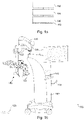
- Fig. 1a shows a block diagram of an example of a system 110 for a microscope system 100.
- the system 110 comprises one or more processors 114 and one or more storage devices 116.
- the system further comprises an interface 112.
- the one or more processors 114 are coupled to the optional interface 112 and the one or more storage devices 116.
- the functionality of the system 110 is provided by the one or more processors 114, e.g. in conjunction with the optional interface 112 and/or the one or more storage devices 116.
- the system is configured to obtain a trigger signal (e.g. via the interface 112).
- the trigger signal indicates a desire of a user of the microscope system to display a visual representation of a control functionality associated with an input device 120; 125 of the microscope system.
- the system is configured to generate, based on the trigger signal, a visual overlay comprising the visual representation.
- the system is configured to provide a display signal to a display device 130 of the microscope system (e.g. via the interface 112).
- the display signal comprises the visual overlay.
- Various embodiments of the present disclosure further provide the microscope system 100, e.g. a surgical microscope system 100, comprising the system 110.
- Fig. 1b shows a schematic diagram of a surgical microscope system for use in ophthalmology comprising the system 100.
- the microscope system 100 further comprises one or more input devices 120; 125, e.g. a food pedal 120 and/or handles 125, the display device 130, and a microscope 160.
- the microscope system 110 may comprise one or more additional, optional features, such as a base unit 105 (that comprises the system 110), an arm 170 that the microscope 160 is attached to, or a microphone 140.
- the microscope 160 may comprise ocular eyepieces 130.
- the microscope system shown in Fig. 1b is a surgical microscope system, which may be used at a surgical site by a surgeon.
- the microscope system shown in Fig. 1b is a surgical microscope system for use in ophthalmology (eye surgery), the same concept may, however, also be used in other types of surgical microscope systems, such as surgical microscope systems for use in neurosurgery.
- the microscope system may comprise, or be used in combination, with one or more additional systems, such as an optical coherence tomography (OCT) system (not shown).
- OCT optical coherence tomography
- Embodiments of the present disclosure relate to a system, a method and a computer program that are suitable for a microscope system, such as the microscope system 100 introduced in connection with Fig. 1b .
- a microscope system comprising the microscope 160 and various components that are used in conjunction with the microscope 160, e.g. a lighting system, an auxiliary display etc.
- the actual microscope is often also referred to as the "optical carrier", as it comprises the optical components of the microscope system.
- a microscope is an optical instrument that is suitable for examining objects that are too small to be examined by the human eye (alone).
- a microscope may provide an optical magnification of an object.
- the optical magnification is often provided for a camera or an imaging sensor.
- the microscope 160 may further comprise one or more optical magnification components that are used to magnify a view on the sample.
- the object being viewed through the microscope may be a sample of organic tissue, e.g. arranged within a petri dish or present in a part of a body of a patient.
- the microscope system 100 may be a microscope system for use in a laboratory, e.g. a microscope that may be used to examine the sample of organic tissue in a petri dish.
- the microscope 160 may be part of a surgical microscope system 100, e.g. a microscope to be used during a surgical procedure. Such a system is shown in Fig. 1b , for example.
- the microscope system may be a system for performing material testing or integrity testing of materials, e.g. of metals or composite materials.
- the system is configured to obtain the trigger signal, which indicates the desire of the user of the microscope system to display a visual representation of the control functionality associated with the input device 120; 125 of the microscope system.
- the trigger signal may originate from two types of sources - either from the input device the visual representation is to be generated for, or from another input device or modality.
- the trigger signal may also indicate the input device that the visual representation is to be generated for.
- the microscope system may comprise one or more input devices (e.g. a plurality of input devices). Depending on the input device the trigger signal originates from (i.e. the input device the trigger signal is obtained from), one of the one or more input devices may be selected, and the visual representation may be generated for the selected input device.
- the system may be configured to obtain the trigger signal from one of the one or more input devices 120; 125 of the microscope system, and to generate the visual overlay with a visual representation of the control functionality associated with the input device the trigger signal is received from (i.e. the input device that the trigger signal originates from).
- the visual representation may relate to said foot pedal.
- the system may be configured to obtain the trigger signal from, or via, a button of the input device.
- the trigger signal may be generated in response to the button of the input device being actuated.
- the trigger device is received from, originates from, and is generated by, an input modality that is different from the input modality the visual representation is generated for.
- the trigger signal may be generated by the system itself, by processing an input signal that is generated by a sensor of the microscope system.
- the microscope system may comprise, or may be coupled with, a microphone 140.
- the system may be configured to process audio captured via the microphone 140, and to generate the trigger signal based on one or more keywords spoken by the user within the captured audio.
- the system may be configured to detect the one or more keywords (or key phrases) within the captured audio, such as "show the functionality of the foot pedal", or "show an overview of the main input devices", or "how do I focus/zoom the microscope".
- the microscope system may comprise other types of sensors as well, such as a camera for performing eye tracking of the user, or a depth sensor for detecting gestures of the user.
- the system may be configured to process the sensor data of the camera or of the depth sensor, and to generate the trigger signal based on the sensor data.
- the trigger signal may be generated via a touch-screen 150 of the microscope system.
- the system may be configured to obtain the trigger signal via a touch-screen 150 of the microscope system.
- the touch-screen may be actuated by the user/surgeon themselves, or by an assistant, to generate the trigger signal.
- the proposed concept can be used with any type of input device.
- the two input devices that are predominately used are the foot pedal 120, and the handle or handles 125 of the microscope system.
- the same concept may be applied to other input devices as well, such as a mouth switch or an eye-tracking system of the microscope system.
- the input device may be one of a foot pedal 120, a handle 125, a mouth switch or an eye-tracking system of the microscope system.
- the visual representation may represent a control functionality associated with a foot pedal 120, with a handle 125 of the microscope system, with a mouth switch of the microscope system, or with an eye-tracking system of the microscope system.
- the input device may be an input device/one or more input devices comprising one or more input modalities that are re-configurable regarding the control functionality associated with the one or more input modalities.
- the control functionality of the input device might not be shown on the input device itself.
- the input device might not be a touchscreen, as in touchscreens, the control functionality of an element of a graphical user interface might always be displayed on the screen.
- an “input device” may relate to the device itself, such as a foot pedal, or a handle
- the “input modality” may relate to the means provided by the input device to trigger a control functionality.
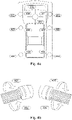
- the input device may comprise a plurality of input modalities, with the plurality of input modalities comprising at least one of one or more buttons, one or more switches, one or more rotary controls, and one or more control sticks.
- the input device "foot pedal” 120 may comprise a plurality of input modalities, e.g.
- buttons that can be pressed, pads that can be tilted in one or another direction, or control sticks that can be tilted in one of multiple directions For example, in Fig. 4a , a foot pedal is shown (i.e. the input device), with six buttons 401, 404, 405, 408, 413 and 414, two pads each being pressable to the left (402, 406) and to the right (403, 407), and a control stick that can be tilted left 409, upwards 410, right 411 and downwards 412, with the buttons, the directions the pads can be pressed and the directions the control stick can be tilted providing a total of 14 input modalities (6 via the buttons, 4 via the pads, and 4 via the control stick).
- the different directions of the gaze of the user may correspond to the input modalities.
- the input modalities may be an "actuation modality" (e.g. a switch to be actuated via the chin), and a four-way joystick to be actuated via the mouth.
- the term "foot pedal” is not used for a single button that can be actuated by foot, but for the entire input device comprising the plurality of input modalities.
- the handles shown in Fig. 4a have two input modalities each, a clockwise turn and a counter-clockwise turn.
- the handle of Fig. 4c has 10 input modalities - six buttons 435-440, and a control stick that can be turned into four directions (431-434).
- a plurality of control functionalities can be associated with a plurality of input modalities of the input device.
- the visual representation may represent a plurality of control functionalities associated with a plurality of input modalities of the input device.
- a visual representation of the input device may be included in the visual representation, e.g. a three-dimensional visual representation.
- the visual representation of the control functionality may comprise a visual representation, such as a three-dimensional representation, of the input device the control functionality is associated with.
- the display device 130 may be a display device for displaying three-dimensional images.
- the display device may be configured to provide the three-dimensional images using different polarizations, with the user/surgeon wearing polarized glasses.
- the trigger signal indicates the desire of a user of the microscope system to display the visual representation of the control functionality associated with the input device 120; 125 of the microscope system.
- the trigger signal is triggered, by the user, in order to display the display the visual representation of the control functionality associated with the input device.
- the visual representation is displayed in response to the trigger signal.
- the visual representation may be shown (only) as long as the trigger signal is active.
- the visual representation may be shown for a pre-defined time in response to the trigger signal, and hidden after the pre-defined time.
- the system may be configured to hide and/or fade out the visual representation after the pre-defined time.
- the system is configured to generate, based on the trigger signal, the visual overlay comprising the visual representation.
- the visual representation may comprise a pictogram representation of the control functionality, or the visual representation may comprise a textual representation of the control functionality.
- the visual representation may comprise a textual or pictogram representation, e.g. as shown in Figs. 3a and 3b .
- the visual overlay may comprise the visual representation of the control functionality associated with the input modalities in a manner that mimics the layout of the input device, e.g.
- the visual representation of the control functionality being located in proximity of a visual representation of the input device itself, e.g. as shown in Figs. 3a to 4c .
- the visual representation may represent a control functionality associated with a foot pedal 120, with a handle 125 of the microscope system, with a mouth switch of the microscope system, or with an eye-tracking system of the microscope system, and/or, in particular, of with the input modalities provided by the respective input device.
- control functionality may relate to any functionality of the microscope system that can be triggered or adapted, e.g. a zoom functionality, a focus functionality, a movement of a robotic arm of the microscope system, an image processing functionality of the microscope system, a display functionality of the microscope system, an illumination functionality of the microscope system (e.g. fluorescence stimulation or visible light illumination) etc.
- control functionality may also relate to further devices that are coupled with the microscope system, such as optical coherence tomography and intraocular lens guidance in the case of a surgical microscope system for use in eye surgery.
- the control functionality may relate to functionality provided by the microscope system and/or to functionality provided by a device that is coupled with, or integrated with, the microscope system, such as an OCT system or a lens guidance system.
- a microscope system may comprise more than a single mode of operation.
- a surgical microscope system for use in eye surgery may have a vitreoretinal mode and an OCT mode.
- different control functionalities may be associated with the input devices / input modalities of the input modalities of the input devices.
- Figs. 3a and 3b examples are shown for an assignment of functionality in a vitreoretinal (VR) and an OCT mode of operation.
- the functionalities All Lights On/Off, Magnification -, Magnification +, OCT Mode On/Off, Focus - Focus +, VR Synchronized Focus +, VR Synchronized Focus -, X-, X+, Y+, Y- and VR Mode On/Off are assigned to the different modalities of the input device.
- the functionalities OCT Live Mode/Freeze, OCT Optimize, OCT Auto Locate, OCT Mode On/Off, OCT Scan, OCT Next Procedure, OCT Z-, OCT Z+, OCT Left, OCT Right, OCT Up, OCT Down, OCT Save b and OCT Change Joystick State are assigned to the different modalities of the input device.
- the input device may have, or may be configured with, two or more sets of functionalities that are associated with the two or more modes of the input device.
- the two or more modes of the input device may be associated with the two or more modes of operation of the microscope system.
- One (i.e. a single one) of the two or more modes may be active at the input device (at a given time).
- the system may be configured to generate the visual representation based on the set of functionalities that is associated with the mode that is active at the input device. In other words, the visual representation may be generated depending on which mode is active at the input device / microscope system.
- the visual overlay may be used.
- the visual overlay may be used to display, in addition to the visual representation of the control functionality associated with the input device, information on further functionality being available. This may enable the microscope system to provide "unlimited functionality" that is available to the user of the microscope system via the visual overlay.
- the user may request the system to display the available functionality via a further trigger signal. In other words, the system may be configured to obtain a further trigger signal.
- the further trigger signal may be obtained similar to the trigger signal specified above, and may originate from one of the input devices, from the touch screen, of be generated by the system based on a sensor input.
- the further trigger signal may indicate a desire of a user of the microscope system to toggle a control functionality associated with the input device.
- the system may be configured to toggle the control functionality associated with the input device based on the further trigger signal.
- the system may be triggered to toggle the control functionality associated with the input device in response to receiving the further trigger signal.
- the functionality being associated with the respective input modalities of the input device may be changed by toggling the control functionality associated with the input device based on the further trigger signal.
- the system may be configured to adapt the visual representation (to show the control functionality that is associated with the input device after toggling) after toggling the control functionality associated with the input device.
- the control functionality being available may be shown in the visual overlay, so the user/surgeon is made aware of the functionality being available, and can select the desired control functionality assisted by the visual overlay.
- the system may be configured to generate the visual overlay such, that the visual overlay comprises a visual representation of a control functionality currently associated with the input device (i.e. the visual representation of the control functionality associated with the input device) and a visual representation of a control functionality available for association with the input device after toggling.
- the available control functionality i.e. the control functionality available for association with the input device after toggling
- the available control functionality may be displayed as part of the visual overlay.
- the visual representation of the control functionality available for association with the input device after toggling may be shown side by side with, or instead of, the visual representation of the control functionality currently associated with the input device, e.g. in response to receiving the further trigger signal, or as long as the further trigger signal is received.
- a smart guidance feature may be provided.
- the system may be configured to select the control functionality available for association with the input device after toggling based on a progress of a surgery being performed with the help of the surgical microscope system.
- the system may be configured to generate the visual overlay such, that the surgeon is guided to select control functionality associated with a subsequent step of the surgery being performed.
- the system is configured to provide the display signal to a display device 130 of the microscope system (e.g. via the interface 112), the display signal comprising the visual overlay.
- the display device may be configured to show the visual overlay based on the display signal, e.g. to inject the visual overlay over the view on the sample based on the display signal.
- the display signal may comprise a video stream or control instructions that comprise the visual overlay, e.g. such that the visual overlay is shown by the respective display device.
- the display device may be one of an ocular display of the microscope and an auxiliary display of the surgical microscope system.
- the view on the sample is often provided via a display, such as a ocular display, an auxiliary display or a headset display, e.g. using a video stream that is generated based on image sensor data of an optical imaging sensor of the respective microscope.
- the visual overlay may be merely overlaid over the video stream.
- the system may be configured to obtain image sensor data of an optical imaging sensor of the microscope, to generate the video stream based on the image sensor data and to generate the display signal by overlaying the visual overlay over the video stream.
- the visual overlay may be overlaid over an optical view of the sample.
- the ocular eyepieces of the microscope may be configured to provide an optical view on the sample
- the display device may be configured to inject the overlay into the optical view on the sample, e.g. using a one-way mirror or a semi-transparent display that is arranged within an optical path of the microscope.
- the microscope may be an optical microscope with at least one optical path.
- One-way mirror(s) may be arranged within the optical path(s), and the visual overlay may be projection onto the one-way mirror(s) and thus overlaid over the view on the sample.
- the display device may be a projection device configured to project the visual overlay towards the mirror(s), e.g.
- a display or displays may be used to provide the overlay within the optical path(s) of the microscope.
- the display device may comprise at least one display being arranged within the optical path(s).
- the display(s) may be one of a projection-based display and a screen-based display, such as a Liquid Crystal Display (LCD) - or an Organic Light Emitting Diode (OLED)-based display.
- the display(s) may be arranged within the eyepiece of the optical stereoscopic microscope, e.g. one display in each of the oculars.
- two displays may be used to turn the oculars of the optical microscope into augmented reality oculars, i.e. an augmented reality eyepiece.
- other technologies may be used to implement the augmented reality eyepiece/oculars.
- the interface 112 may correspond to one or more inputs and/or outputs for receiving and/or transmitting information, which may be in digital (bit) values according to a specified code, within a module, between modules or between modules of different entities.
- the interface 112 may comprise interface circuitry configured to receive and/or transmit information.
- the one or more processors 114 may be implemented using one or more processing units, one or more processing devices, any means for processing, such as a processor, a computer or a programmable hardware component being operable with accordingly adapted software.
- the described function of the one or more processors 114 may as well be implemented in software, which is then executed on one or more programmable hardware components.
- Such hardware components may comprise a general-purpose processor, a Digital Signal Processor (DSP), a micro-controller, etc.
- the one or more storage devices 116 may comprise at least one element of the group of a computer readable storage medium, such as an magnetic or optical storage medium, e.g. a hard disk drive, a flash memory, Floppy-Disk, Random Access Memory (RAM), Programmable Read Only Memory (PROM), Erasable Programmable Read Only Memory (EPROM), an Electronically Erasable Programmable Read Only Memory (EEPROM), or a network storage.
- a computer readable storage medium such as an magnetic or optical storage medium, such as an magnetic or optical storage medium, e.g. a hard disk drive, a flash memory, Floppy-Disk, Random Access Memory (RAM), Programmable Read Only Memory (PROM), Erasable Programmable Read Only Memory (EPROM), an Electronically Erasable Programmable Read Only Memory (EEPROM), or a network storage.
- the system or microscope system may comprise one or more additional optional features corresponding to one or more aspects of the proposed concept or one or more examples described above or below.
- Fig. 2 shows a flow chart of an example of a corresponding method for a microscope system.
- the method comprises obtaining 210 a trigger signal.
- the trigger signal indicates a desire of a user of the microscope system to display a visual representation of a control functionality associated with an input device of the microscope system.
- the method comprises generating 220 based on the trigger signal, a visual overlay comprising the visual representation.
- the method comprises providing 230 a display signal to a display device of the microscope system, the display signal comprising the visual overlay.
- the method may comprise one or more additional optional features corresponding to one or more aspects of the proposed concept or one or more examples described above or below.
- Various aspects of the present disclosure relate to surgical control guidance for microscope interactions.
- a foot pedal also known as footswitch
- handle controls play a crucial role in surgery. While there are some subtle variations among models and manufacturers, the basics of the microscope foot pedal and operation of the microscope are similar. The primary microscope controls are focus, zoom and centration. Additional functions include the ability to turn the microscope light on and off as well as adjust the brightness.
- typical operation can involve multiple foot pedals - a surgeon may control a foot pedal for the microscope controls, a foot pedal for phacoemulsification to control the phaco irrigation, aspiration and ultrasonic power delivery, a foot pedal for vitrectomy and a foot pedal for laser photocoagulation.
- a microscope handle can be programmed with up to 10 functions each to provide a total of 20 functions on both right and left handles.
- Figs. 3a and 3b show schematic diagrams of functionalities being assigned to a foot pedal of a surgical microscope system.
- Figs. 3a and 3b illustrate how new functions for advanced surgical guidance applications introduces additional complexity, where experienced surgeons may remember specific functions which have been programmed on the foot pedal and handles, when toggling between surgical modes (e.g. vitreoretinal, OCT functions).
- the foot pedals 3a and 3b have a plurality of input modalities, comprising a lower left button 301a/b, a lower right button 304a/b, a lower pad comprising a left side 302a/b and a right side 303a/b, a middle left button 305a/b, a middle right button 306a/b, a middle pad comprising a left side 307a/b and a right side 308a/b, a top control stick having a stick that can be moved into a left position 309a/b, top position 310a/b, right position 311a/b and bottom position 312a/b, a top left button 313a/b and a top right button 314a/b.
- Fig. 3a shows an exemplary assignment of functionalities for a vitreoretinal mode, with the (control) functionality All Lights On/Off being assigned to the lower left button 301a, Magnification - assigned to the left side 302a of the lower pad, Magnification + being assigned to the right side 303a of the lower pad, OCT Mode On/Off being assigned to the lower right button 304a, Focus - being assigned to the middle left button 305a, Focus + being assigned to the middle right button 306a, VR Synchronized Focus + being assigned to the left side 307a of the middle pad, VR Synchronized Focus - being assigned to the right side 308a of the middle pad, X- being assigned to the top control stick being moved to the left position 309a, X+ being assigned to the top control stick being moved to the right position 311a, Y+ being assigned to the top control stick being moved to the top position 310a, Y- being assigned to the top control stick being moved to the bottom position 312a, nothing being assigned to
- Fig. 3b shows an exemplary assignment of functionalities for a OCT mode, with the (control) functionality OCT Live Mode/Freeze being assigned to the lower left button 301b, OCT Optimize being assigned to the left side 302b of the lower pad, OCT Auto Locate being assigned to the right side 303b of the lower pad, OCT Mode On/Off being assigned to the lower right button 304b, OCT Scan being assigned to the middle left button 305b, OCT Next Procedure being assigned to the middle right button 306b, OCT Z- being assigned to the left side 307b of the middle pad, OCT Z+ being assigned to the right side 308b of the middle pad, OCT Left being assigned to the top control stick being moved to the left position 309b, OCT Right being assigned to the top control stick being moved to the right position 311b, OCT Up being assigned to the top control stick being moved to the top position 310b, OCT Down being assigned to the top control stick being moved to the bottom position 312b, OCT Save being assigned to the top left button
- Limited interactions may be available on the foot pedal and handles, which may limit the number of functions which can be programmed on the controls. For example, in ophthalmology, 4 functionalities may be assigned to various modalities on the handles with the addition of 12-14 functionalities on the foot pedals and in microsurgery, up to a maximum of 10 on the handles. Surgeons may prioritize and program before surgery which functions are needed, with the remaining unselected functions inaccessible.
- Figs. 4a to 4c show schematic diagrams of input devices for a microscope system, and of the input modalities of the input devices.
- Fig. 4a and 4b show the limited interactions are available on the foot pedal and handles, in ophthalmology, 4 on the handles (clockwise rotation 421 on the left side, counterclockwise rotation 422 on the left side, clockwise rotation 423 on the right side and counterclockwise rotation 424 on the right side) with the addition of 12-14 on the foot pedals (a lower left button 401, a lower right button 404, a lower pad comprising a left side 402 and a right side 403, a middle left button 405, a middle right button 406, a middle pad comprising a left side 407 and a right side 408, a top control stick having a stick that can be moved into a left position 409, top position 410, right position 411 and bottom position 412, a top left button 413 and a top right button 414).
- Fig. 4c shows the limited interactions that are available on the handles, in microsurgery, up to a maximum of 10 on the handles (a top control stick being moved into a top 431, left 432, right 433 and bottom 434 position, an upper left button 435, an upper right button 436, a lower left button 437, a lower right button 438, a right side button 439 and a back button 440).
- This overlay may display the functions pre-programmed in the handles or footswitch as a reminder to the surgeons during operation.
- the overlay can be activated by triggering a dedicated button on the handles or footswitch, or via the user interface on the microscope touch screens, or via activation of any of the handles or footswitch functions.
- the trigger signal may be generated in response to triggering a dedicated button on the handles or footswitch, or via the user interface on the microscope touch screens, or via activation of any of the handles or footswitch functions.
- This overlay can be faded in and faded out automatically without interruption to the surgical workflow.
- a surgical guidance overlay i.e. the visual overlay
- the visual overlay of the surgeon's controls, i.e. the visual representation of the control functionality, (via footswitch or handles) is projected on the microscope stand monitor, heads-up 3D display, external operating room monitors or digital viewers.
- This overlay provides a quick guide for surgeons to reference from during surgery.
- the overlay can be displayed on the heads-up 3D display or any digital viewers to allow the surgeon to have an undisrupted view from the surgical workflow.
- the input devices, and the microscope system may support multiple modes of operation, or short: modes.
- the overlay may display the associated functions of the foot pedal buttons and handle interactions according to the surgical mode in use during the operation. The functions displayed may vary across modes.
- a smart guidance feature may be provided.
- smart guidance features may be integrated to prompt and guide the surgeon to select the next function in the surgical step, to improve clinical workflow efficiency.
- the overlay can also be programmed to display functionalities and guidance from 3rd party accessories, such as pedal controls for the phacoemulsification or vitreoretinal instruments, to allow for a surgical cockpit experience for the surgeon wherein all useful data and controls are displayed to be captured by the surgeon at a single sacrifice.
- 3rd party accessories such as pedal controls for the phacoemulsification or vitreoretinal instruments
- the overlay may be displayed as a transparent fade in layer upon activation, which may fade out automatically without an additional step needed.
- the surgical guidance overlay may be activated by means of triggering a dedicated pre-programmed interaction on the handles or footswitch, or via the touch interfaces on the microscope monitors, or automatically activated when a standard function on the handles or footswitch is triggered.
- the surgical guidance overlay can also be activated by other means, such as voice recognition, head movement, eye tracking or a touch enabled interface on the foot pedal or handles.
- the overlay can provide an unlimited selection of functions to the surgeon by displaying on-screen, a list of options which can be rotated through for selection.
- the surgical guidance overlay can provide an unlimited range of functionalities which can be displayed on-screen for selection and activation by the surgeon. This allows the surgeons to go beyond what can be pre-programmed on the foot pedal (up to 14 functions) or on the handles (ophthalmology up to 4, microsurgery up to 10 functions).
- the additional functions i.e. the "unlimited functionality" can be displayed as a rotary menu or a pop-up menu on screen to provide a range of functions which can be selected for activation by the foot pedal, handles or touch interfaces connected to the microscope.
- the additional functions displayed can either be a range of recommended pre-sets based on the surgical mode in operation, or the surgeons can pre-select their favorite functions to be displayed on-screen for activation or deactivation. This is especially beneficial given that more and more functionalities are integrated in microscope systems to guide the surgical workflow, such as optical coherence tomography and intraocular lens guidance.
- new software features such as tool tracking, feature recognition, voice recognition, etc.
- the surgical guidance overlay can provide a platform to enable this, allowing surgeons to operate beyond the limited interactions on handles and foot switches.
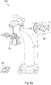
- Figs. 5a and 5b show a schematic diagram of a surgical guidance overlay being displayed on a display device of a microscope system.
- Fig. 5a shows foot pedal 120 or handles functions 125 displayed as an overlay on the microscope display 130 of a microscope system 500.
- This overlay can be activated by triggering a dedicated button on the handles or footswitch, or via the user interface on the microscope touch screens, or via activation of any of the handles or footswitch functions.
- FIG. 5b shows foot pedal or handles functions displayed as an overlay on a 3D heads-up surgical display 130 as part of the surgical cockpit experience in another implementation of the microscope system 500, Again, this overlay can be activated by triggering a dedicated button on the handles or footswitch, or via the user interface on the microscope touch screens, or via activation of any of the handles or footswitch functions
- FIG. 6 shows an example of an on-screen menu, with menu items 610 (Activate Tool Tracking), 620 (Activate Digital Filters), 630 (Activate Voice Command), 640 (OCT Playback), 650 OCT Scan, 660 (Photo Capture) and 670 (Video Record).
- the surgical guidance overlay may comprise one or more additional optional features corresponding to one or more aspects of the proposed concept or one or more examples described above or below.
- aspects have been described in the context of an apparatus, it is clear that these aspects also represent a description of the corresponding method, where a block or device corresponds to a method step or a feature of a method step. Analogously, aspects described in the context of a method step also represent a description of a corresponding block or item or feature of a corresponding apparatus.
- a microscope comprising a system as described in connection with one or more of the Figs. 1 to 6 .
- a microscope may be part of or connected to a system as described in connection with one or more of the Figs. 1 to 6 .
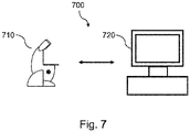
- Fig. 7 shows a schematic illustration of a system 700 configured to perform a method described herein.
- the system 700 comprises a microscope 710 and a computer system 720.
- the microscope 710 is configured to take images and is connected to the computer system 720.
- the computer system 720 is configured to execute at least a part of a method described herein.
- the computer system 720 may be configured to execute a machine learning algorithm.
- the computer system 720 and microscope 710 may be separate entities but can also be integrated together in one common housing.
- the computer system 720 may be part of a central processing system of the microscope 710 and/or the computer system 720 may be part of a subcomponent of the microscope 710, such as a sensor, an actor, a camera or an illumination unit, etc. of the microscope 710.
- the computer system 720 may be a local computer device (e.g. personal computer, laptop, tablet computer or mobile phone) with one or more processors and one or more storage devices or may be a distributed computer system (e.g. a cloud computing system with one or more processors and one or more storage devices distributed at various locations, for example, at a local client and/or one or more remote server farms and/or data centers).
- the computer system 720 may comprise any circuit or combination of circuits.
- the computer system 720 may include one or more processors which can be of any type.
- processor may mean any type of computational circuit, such as but not limited to a microprocessor, a microcontroller, a complex instruction set computing (CISC) microprocessor, a reduced instruction set computing (RISC) microprocessor, a very long instruction word (VLIW) microprocessor, a graphics processor, a digital signal processor (DSP), multiple core processor, a field programmable gate array (FPGA), for example, of a microscope or a microscope component (e.g. camera) or any other type of processor or processing circuit.
- CISC complex instruction set computing
- RISC reduced instruction set computing
- VLIW very long instruction word
- DSP digital signal processor
- FPGA field programmable gate array
- circuits may be included in the computer system 720 may be a custom circuit, an application-specific integrated circuit (ASIC), or the like, such as, for example, one or more circuits (such as a communication circuit) for use in wireless devices like mobile telephones, tablet computers, laptop computers, two-way radios, and similar electronic systems.
- the computer system 720 may include one or more storage devices, which may include one or more memory elements suitable to the particular application, such as a main memory in the form of random access memory (RAM), one or more hard drives, and/or one or more drives that handle removable media such as compact disks (CD), flash memory cards, digital video disk (DVD), and the like.
- RAM random access memory
- CD compact disks
- DVD digital video disk
- the computer system 720 may also include a display device, one or more speakers, and a keyboard and/or controller, which can include a mouse, trackball, touch screen, voice-recognition device, or any other device that permits a system user to input information into and receive information from the computer system 720.
- a display device one or more speakers
- a keyboard and/or controller which can include a mouse, trackball, touch screen, voice-recognition device, or any other device that permits a system user to input information into and receive information from the computer system 720.
- Some or all of the method steps may be executed by (or using) a hardware apparatus, like for example, a processor, a microprocessor, a programmable computer or an electronic circuit. In some embodiments, some one or more of the most important method steps may be executed by such an apparatus.
- embodiments of the invention can be implemented in hardware or in software.
- the implementation can be performed using a non-transitory storage medium such as a digital storage medium, for example a floppy disc, a DVD, a Blu-Ray, a CD, a ROM, a PROM, and EPROM, an EEPROM or a FLASH memory, having electronically readable control signals stored thereon, which cooperate (or are capable of cooperating) with a programmable computer system such that the respective method is performed. Therefore, the digital storage medium may be computer readable.
- Some embodiments according to the invention comprise a data carrier having electronically readable control signals, which are capable of cooperating with a programmable computer system, such that one of the methods described herein is performed.
- embodiments of the present invention can be implemented as a computer program product with a program code, the program code being operative for performing one of the methods when the computer program product runs on a computer.
- the program code may, for example, be stored on a machine readable carrier.
- inventions comprise the computer program for performing one of the methods described herein, stored on a machine readable carrier.
- an embodiment of the present invention is, therefore, a computer program having a program code for performing one of the methods described herein, when the computer program runs on a computer.
- a further embodiment of the present invention is, therefore, a storage medium (or a data carrier, or a computer-readable medium) comprising, stored thereon, the computer program for performing one of the methods described herein when it is performed by a processor.
- the data carrier, the digital storage medium or the recorded medium are typically tangible and/or non-transitionary.
- a further embodiment of the present invention is an apparatus as described herein comprising a processor and the storage medium.
- a further embodiment of the invention is, therefore, a data stream or a sequence of signals representing the computer program for performing one of the methods described herein.
- the data stream or the sequence of signals may, for example, be configured to be transferred via a data communication connection, for example, via the internet.
- a further embodiment comprises a processing means, for example, a computer or a programmable logic device, configured to, or adapted to, perform one of the methods described herein.
- a processing means for example, a computer or a programmable logic device, configured to, or adapted to, perform one of the methods described herein.
- a further embodiment comprises a computer having installed thereon the computer program for performing one of the methods described herein.
- a further embodiment according to the invention comprises an apparatus or a system configured to transfer (for example, electronically or optically) a computer program for performing one of the methods described herein to a receiver.
- the receiver may, for example, be a computer, a mobile device, a memory device or the like.
- the apparatus or system may, for example, comprise a file server for transferring the computer program to the receiver.
- a programmable logic device for example, a field programmable gate array
- a field programmable gate array may cooperate with a microprocessor in order to perform one of the methods described herein.
- the methods are preferably performed by any hardware apparatus.
Landscapes
- Health & Medical Sciences (AREA)
- Life Sciences & Earth Sciences (AREA)
- Engineering & Computer Science (AREA)
- Surgery (AREA)
- General Health & Medical Sciences (AREA)
- Biomedical Technology (AREA)
- Medical Informatics (AREA)
- Public Health (AREA)
- Heart & Thoracic Surgery (AREA)
- Molecular Biology (AREA)
- Animal Behavior & Ethology (AREA)
- Veterinary Medicine (AREA)
- Nuclear Medicine, Radiotherapy & Molecular Imaging (AREA)
- Pathology (AREA)
- Oral & Maxillofacial Surgery (AREA)
- Primary Health Care (AREA)
- Epidemiology (AREA)
- Physics & Mathematics (AREA)
- Biophysics (AREA)
- Ophthalmology & Optometry (AREA)
- Robotics (AREA)
- Human Computer Interaction (AREA)
- Business, Economics & Management (AREA)
- General Business, Economics & Management (AREA)
- Microscoopes, Condenser (AREA)
- User Interface Of Digital Computer (AREA)
Priority Applications (5)
| Application Number | Priority Date | Filing Date | Title |
|---|---|---|---|
| EP20203489.8A EP3989236A1 (fr) | 2020-10-23 | 2020-10-23 | Système pour un système de microscope et procédé et programme informatique correspondants |
| CN202180071419.4A CN116368571A (zh) | 2020-10-23 | 2021-10-18 | 用于显微镜系统的系统及相应的方法和计算机程序 |
| JP2023524826A JP2023546609A (ja) | 2020-10-23 | 2021-10-18 | 顕微鏡システム用のシステムおよび対応する方法およびコンピュータプログラム |
| US18/249,986 US20230404699A1 (en) | 2020-10-23 | 2021-10-18 | System for a Microscope System and Corresponding Method and Computer Program |
| PCT/EP2021/078786 WO2022084240A1 (fr) | 2020-10-23 | 2021-10-18 | Système pour un systeme de microscope, procédé et programme informatique correspondants |
Applications Claiming Priority (1)
| Application Number | Priority Date | Filing Date | Title |
|---|---|---|---|
| EP20203489.8A EP3989236A1 (fr) | 2020-10-23 | 2020-10-23 | Système pour un système de microscope et procédé et programme informatique correspondants |
Publications (1)
| Publication Number | Publication Date |
|---|---|
| EP3989236A1 true EP3989236A1 (fr) | 2022-04-27 |
Family
ID=73013341
Family Applications (1)
| Application Number | Title | Priority Date | Filing Date |
|---|---|---|---|
| EP20203489.8A Pending EP3989236A1 (fr) | 2020-10-23 | 2020-10-23 | Système pour un système de microscope et procédé et programme informatique correspondants |
Country Status (5)
| Country | Link |
|---|---|
| US (1) | US20230404699A1 (fr) |
| EP (1) | EP3989236A1 (fr) |
| JP (1) | JP2023546609A (fr) |
| CN (1) | CN116368571A (fr) |
| WO (1) | WO2022084240A1 (fr) |
Cited By (2)
| Publication number | Priority date | Publication date | Assignee | Title |
|---|---|---|---|---|
| DE102022119613A1 (de) | 2022-08-04 | 2024-02-15 | B. Braun New Ventures GmbH | Medizinisches Roboter-Führungssystem mit integriertem Touchdisplay und Bedienungsverfahren |
| EP4338699A1 (fr) * | 2022-09-15 | 2024-03-20 | Leica Instruments (Singapore) Pte Ltd | Système, procédé et programme informatique pour un système d'imagerie chirurgicale |
Citations (4)
| Publication number | Priority date | Publication date | Assignee | Title |
|---|---|---|---|---|
| US20190099226A1 (en) * | 2017-10-04 | 2019-04-04 | Novartis Ag | Surgical suite integration and optimization |
| US20190361592A1 (en) * | 2018-05-23 | 2019-11-28 | Alcon Inc. | System and method of utilizing surgical tooling equipment with graphical user interfaces |
| WO2020084625A1 (fr) * | 2018-10-25 | 2020-04-30 | Beyeonics Surgical Ltd. | Iu destinée à un système de visiocasque |
| AU2019261643A1 (en) * | 2018-04-27 | 2020-09-24 | Alcon Inc. | Stereoscopic visualization camera and integrated robotics platform |
Family Cites Families (4)
| Publication number | Priority date | Publication date | Assignee | Title |
|---|---|---|---|---|
| CN104640514B (zh) * | 2012-09-17 | 2019-05-07 | 直观外科手术操作公司 | 针对远程操作的手术器械功能分配输入设备的方法和系统 |
| US10932871B2 (en) * | 2012-12-25 | 2021-03-02 | Kawasaki Jukogyo Kabushiki Kaisha | Surgical robot |
| JP6856594B2 (ja) * | 2018-09-25 | 2021-04-07 | 株式会社メディカロイド | 手術システムおよび表示方法 |
| US20230169698A1 (en) * | 2020-04-24 | 2023-06-01 | Ohm Savanayana | Microscope system and corresponding system, method and computer program for a microscope system |
-
2020
- 2020-10-23 EP EP20203489.8A patent/EP3989236A1/fr active Pending
-
2021
- 2021-10-18 JP JP2023524826A patent/JP2023546609A/ja active Pending
- 2021-10-18 WO PCT/EP2021/078786 patent/WO2022084240A1/fr active Application Filing
- 2021-10-18 US US18/249,986 patent/US20230404699A1/en active Pending
- 2021-10-18 CN CN202180071419.4A patent/CN116368571A/zh active Pending
Patent Citations (4)
| Publication number | Priority date | Publication date | Assignee | Title |
|---|---|---|---|---|
| US20190099226A1 (en) * | 2017-10-04 | 2019-04-04 | Novartis Ag | Surgical suite integration and optimization |
| AU2019261643A1 (en) * | 2018-04-27 | 2020-09-24 | Alcon Inc. | Stereoscopic visualization camera and integrated robotics platform |
| US20190361592A1 (en) * | 2018-05-23 | 2019-11-28 | Alcon Inc. | System and method of utilizing surgical tooling equipment with graphical user interfaces |
| WO2020084625A1 (fr) * | 2018-10-25 | 2020-04-30 | Beyeonics Surgical Ltd. | Iu destinée à un système de visiocasque |
Cited By (3)
| Publication number | Priority date | Publication date | Assignee | Title |
|---|---|---|---|---|
| DE102022119613A1 (de) | 2022-08-04 | 2024-02-15 | B. Braun New Ventures GmbH | Medizinisches Roboter-Führungssystem mit integriertem Touchdisplay und Bedienungsverfahren |
| EP4338699A1 (fr) * | 2022-09-15 | 2024-03-20 | Leica Instruments (Singapore) Pte Ltd | Système, procédé et programme informatique pour un système d'imagerie chirurgicale |
| WO2024056854A1 (fr) * | 2022-09-15 | 2024-03-21 | Leica Instruments (Singapore) Pte. Ltd. | Système, procédé et programme informatique pour un système d'imagerie chirurgicale |
Also Published As
| Publication number | Publication date |
|---|---|
| CN116368571A (zh) | 2023-06-30 |
| WO2022084240A1 (fr) | 2022-04-28 |
| US20230404699A1 (en) | 2023-12-21 |
| JP2023546609A (ja) | 2023-11-06 |
Similar Documents
| Publication | Publication Date | Title |
|---|---|---|
| US11989930B2 (en) | UI for head mounted display system | |
| JP6463428B2 (ja) | ジェスチャ制御機能を有する手術用顕微鏡、および、手術用顕微鏡のジェスチャ制御を行う方法 | |
| US7594188B2 (en) | Operating menu for a surgical microscope | |
| US9645785B1 (en) | Heads-up displays for augmented reality network in a medical environment | |
| US20230404699A1 (en) | System for a Microscope System and Corresponding Method and Computer Program | |
| US6847336B1 (en) | Selectively controllable heads-up display system | |
| US10992857B2 (en) | Input control device, input control method, and operation system | |
| US11527321B2 (en) | Augmented reality for predictive workflow in an operating room | |
| SG182880A1 (en) | A method and system for interaction with micro-objects | |
| EP3907585B1 (fr) | Systèmes et procédés de commande d'un écran de salle d'opération à l'aide d'un casque de réalité augmentée | |
| EP3454177A1 (fr) | Procédé et système de commande de geste efficace de l'équipement | |
| US20230169698A1 (en) | Microscope system and corresponding system, method and computer program for a microscope system | |
| CA3117533A1 (fr) | Iu destinee a un systeme de visiocasque | |
| Sonntag et al. | On-body IE: a head-mounted multimodal augmented reality system for learning and recalling faces | |
| US20220331038A1 (en) | User interface for controlling a surgical system | |
| WO2018087977A1 (fr) | Dispositif de traitement d'informations, procédé de traitement d'informations et programme | |
| CN117981009A (zh) | 外科显微镜系统以及用于外科显微镜系统的相应系统、方法和计算机程序 | |
| US20210038329A1 (en) | Augmented reality using eye tracking in a robot assisted srugical system | |
| JP7367041B2 (ja) | 頭部装着型ディスプレイシステムのためのui |
Legal Events
| Date | Code | Title | Description |
|---|---|---|---|
| PUAI | Public reference made under article 153(3) epc to a published international application that has entered the european phase |
Free format text: ORIGINAL CODE: 0009012 |
|
| STAA | Information on the status of an ep patent application or granted ep patent |
Free format text: STATUS: THE APPLICATION HAS BEEN PUBLISHED |
|
| AK | Designated contracting states |
Kind code of ref document: A1 Designated state(s): AL AT BE BG CH CY CZ DE DK EE ES FI FR GB GR HR HU IE IS IT LI LT LU LV MC MK MT NL NO PL PT RO RS SE SI SK SM TR |
|
| STAA | Information on the status of an ep patent application or granted ep patent |
Free format text: STATUS: REQUEST FOR EXAMINATION WAS MADE |
|
| 17P | Request for examination filed |
Effective date: 20221027 |
|
| RBV | Designated contracting states (corrected) |
Designated state(s): AL AT BE BG CH CY CZ DE DK EE ES FI FR GB GR HR HU IE IS IT LI LT LU LV MC MK MT NL NO PL PT RO RS SE SI SK SM TR |
|
| P01 | Opt-out of the competence of the unified patent court (upc) registered |
Effective date: 20230414 |