EP3989103B1 - Scanning equipment, method, device, and storage medium - Google Patents
Scanning equipment, method, device, and storage medium Download PDFInfo
- Publication number
- EP3989103B1 EP3989103B1 EP20863865.0A EP20863865A EP3989103B1 EP 3989103 B1 EP3989103 B1 EP 3989103B1 EP 20863865 A EP20863865 A EP 20863865A EP 3989103 B1 EP3989103 B1 EP 3989103B1
- Authority
- EP
- European Patent Office
- Prior art keywords
- scanning
- item
- rotation component
- rotation
- locating
- Prior art date
- Legal status (The legal status is an assumption and is not a legal conclusion. Google has not performed a legal analysis and makes no representation as to the accuracy of the status listed.)
- Active
Links
Images


Classifications
-
- G—PHYSICS
- G01—MEASURING; TESTING
- G01G—WEIGHING
- G01G19/00—Weighing apparatus or methods adapted for special purposes not provided for in the preceding groups
- G01G19/62—Over or under weighing apparatus
-
- G—PHYSICS
- G06—COMPUTING OR CALCULATING; COUNTING
- G06K—GRAPHICAL DATA READING; PRESENTATION OF DATA; RECORD CARRIERS; HANDLING RECORD CARRIERS
- G06K7/00—Methods or arrangements for sensing record carriers, e.g. for reading patterns
- G06K7/10—Methods or arrangements for sensing record carriers, e.g. for reading patterns by electromagnetic radiation, e.g. optical sensing; by corpuscular radiation
- G06K7/10544—Methods or arrangements for sensing record carriers, e.g. for reading patterns by electromagnetic radiation, e.g. optical sensing; by corpuscular radiation by scanning of the records by radiation in the optical part of the electromagnetic spectrum
- G06K7/10821—Methods or arrangements for sensing record carriers, e.g. for reading patterns by electromagnetic radiation, e.g. optical sensing; by corpuscular radiation by scanning of the records by radiation in the optical part of the electromagnetic spectrum further details of bar or optical code scanning devices
-
- G—PHYSICS
- G01—MEASURING; TESTING
- G01G—WEIGHING
- G01G19/00—Weighing apparatus or methods adapted for special purposes not provided for in the preceding groups
- G01G19/40—Weighing apparatus or methods adapted for special purposes not provided for in the preceding groups with provisions for indicating, recording, or computing price or other quantities dependent on the weight
- G01G19/42—Weighing apparatus or methods adapted for special purposes not provided for in the preceding groups with provisions for indicating, recording, or computing price or other quantities dependent on the weight for counting by weighing
-
- G—PHYSICS
- G01—MEASURING; TESTING
- G01G—WEIGHING
- G01G19/00—Weighing apparatus or methods adapted for special purposes not provided for in the preceding groups
- G01G19/52—Weighing apparatus combined with other objects, e.g. furniture
-
- G—PHYSICS
- G06—COMPUTING OR CALCULATING; COUNTING
- G06K—GRAPHICAL DATA READING; PRESENTATION OF DATA; RECORD CARRIERS; HANDLING RECORD CARRIERS
- G06K7/00—Methods or arrangements for sensing record carriers, e.g. for reading patterns
- G06K7/10—Methods or arrangements for sensing record carriers, e.g. for reading patterns by electromagnetic radiation, e.g. optical sensing; by corpuscular radiation
- G06K7/10544—Methods or arrangements for sensing record carriers, e.g. for reading patterns by electromagnetic radiation, e.g. optical sensing; by corpuscular radiation by scanning of the records by radiation in the optical part of the electromagnetic spectrum
- G06K7/10712—Fixed beam scanning
- G06K7/10762—Relative movement
-
- G—PHYSICS
- G06—COMPUTING OR CALCULATING; COUNTING
- G06K—GRAPHICAL DATA READING; PRESENTATION OF DATA; RECORD CARRIERS; HANDLING RECORD CARRIERS
- G06K7/00—Methods or arrangements for sensing record carriers, e.g. for reading patterns
- G06K7/10—Methods or arrangements for sensing record carriers, e.g. for reading patterns by electromagnetic radiation, e.g. optical sensing; by corpuscular radiation
- G06K7/10544—Methods or arrangements for sensing record carriers, e.g. for reading patterns by electromagnetic radiation, e.g. optical sensing; by corpuscular radiation by scanning of the records by radiation in the optical part of the electromagnetic spectrum
- G06K7/10821—Methods or arrangements for sensing record carriers, e.g. for reading patterns by electromagnetic radiation, e.g. optical sensing; by corpuscular radiation by scanning of the records by radiation in the optical part of the electromagnetic spectrum further details of bar or optical code scanning devices
- G06K7/10831—Arrangement of optical elements, e.g. lenses, mirrors, prisms
-
- G—PHYSICS
- G06—COMPUTING OR CALCULATING; COUNTING
- G06K—GRAPHICAL DATA READING; PRESENTATION OF DATA; RECORD CARRIERS; HANDLING RECORD CARRIERS
- G06K7/00—Methods or arrangements for sensing record carriers, e.g. for reading patterns
- G06K7/10—Methods or arrangements for sensing record carriers, e.g. for reading patterns by electromagnetic radiation, e.g. optical sensing; by corpuscular radiation
- G06K7/10544—Methods or arrangements for sensing record carriers, e.g. for reading patterns by electromagnetic radiation, e.g. optical sensing; by corpuscular radiation by scanning of the records by radiation in the optical part of the electromagnetic spectrum
- G06K7/10821—Methods or arrangements for sensing record carriers, e.g. for reading patterns by electromagnetic radiation, e.g. optical sensing; by corpuscular radiation by scanning of the records by radiation in the optical part of the electromagnetic spectrum further details of bar or optical code scanning devices
- G06K7/10861—Methods or arrangements for sensing record carriers, e.g. for reading patterns by electromagnetic radiation, e.g. optical sensing; by corpuscular radiation by scanning of the records by radiation in the optical part of the electromagnetic spectrum further details of bar or optical code scanning devices sensing of data fields affixed to objects or articles, e.g. coded labels
-
- G—PHYSICS
- G06—COMPUTING OR CALCULATING; COUNTING
- G06K—GRAPHICAL DATA READING; PRESENTATION OF DATA; RECORD CARRIERS; HANDLING RECORD CARRIERS
- G06K7/00—Methods or arrangements for sensing record carriers, e.g. for reading patterns
- G06K7/10—Methods or arrangements for sensing record carriers, e.g. for reading patterns by electromagnetic radiation, e.g. optical sensing; by corpuscular radiation
- G06K2007/10504—Data fields affixed to objects or articles
-
- G—PHYSICS
- G06—COMPUTING OR CALCULATING; COUNTING
- G06Q—INFORMATION AND COMMUNICATION TECHNOLOGY [ICT] SPECIALLY ADAPTED FOR ADMINISTRATIVE, COMMERCIAL, FINANCIAL, MANAGERIAL OR SUPERVISORY PURPOSES; SYSTEMS OR METHODS SPECIALLY ADAPTED FOR ADMINISTRATIVE, COMMERCIAL, FINANCIAL, MANAGERIAL OR SUPERVISORY PURPOSES, NOT OTHERWISE PROVIDED FOR
- G06Q10/00—Administration; Management
- G06Q10/08—Logistics, e.g. warehousing, loading or distribution; Inventory or stock management
- G06Q10/087—Inventory or stock management, e.g. order filling, procurement or balancing against orders
Definitions
- the present disclosure relates to the field of logistics, in particular to a scanning apparatus, a scanning method, a scanning device and a storage medium.
- a first node is to put items into warehouses, which is usually managed through the serial numbers of the items.
- the items to be input into the warehouses are attached with the serial numbers and the serial numbers are scanned one by one, and finally the acceptance and warehousing ofitems are completed.
- Document WO2010123458 provides an apparatus for acquiring an image of a pallet load.
- the apparatus operates a line scan camera arranged for movement in a movement plane to acquire the image.
- Document CN207802110 discloses a full angle image automatic acquisition device, the device can realize 360 degrees controllable automations of object and shoot to obtain the all angles picture of object.
- Full angle image automatic acquisition device includes supporting part and image acquisition portion, the supporting part with the adjacent setting of image acquisition portion, the supporting part includes the carousel and triggers the portion, image acquisition portion includes image sensor and connects the converter, trigger the portion with the image sensor electricity is connected.
- Document CN110147692 relates to a group reading and code scanning system for logistics.
- the system includes a carrier; the rotary stacking table is mounted on the ground on the front side of the carrier; the displacement adjusting mechanism is mounted on the carrier; at least one group reading and code scanning mechanism is arranged, is in transmission connection with the displacement adjusting mechanism and is used for scanning and reading the cargo information bar code information of the logistics packaging box on the rotary stacking platform, and the displacement adjusting mechanism can drive the at least one group reading and code scanning mechanism to move up and down; the control host is electrically connected with the displacement adjusting mechanism and the group reading and code scanning mechanism and used for controlling operation of the displacement adjusting mechanism and the group reading and code scanning mechanism, and the control host is in communication connection with the background data processing terminal.
- the present disclosure provides a scanning apparatus, and the apparatus includes a rotatable rotation component, a scanning device, and a positioning (locating) device.
- the positioning (locating) device is configured for positioning (locating) the rotation component when the rotation component rotates to different predetermined positions respectively, and the scanning device is configured for scanning an item placed on the positioned (located) rotation component.
- a plurality of positioning (locating) marks is arranged at a periphery of a first surface of the rotation component around an axis of a rotation shaft of the rotation component, and each of the positioning (locating) marks corresponds to one of the predetermined positions, and a radial distance between each of the positioning (locating) marks and the rotation shaft is L.
- the positioning device is configured to perform a detection on the rotation component, a detection position of the positioning (locating) device is located on the first surface of the rotation component, and a radial distance between the detection position and the rotation shaft is L, so that during a rotation of the rotation component, the rotation component is positioned (located) when the positioning (locating) device detects the positioning (locating) mark at the detection position.
- the positioning (locating) mark is a light-transmitting through hole
- the light-transmitting through hole penetrates the rotation component
- the positioning (locating) device is a photoelectric sensor
- a probe of the photoelectric sensor faces the detection position, so that during the rotation of the rotation component, the rotation component is positioned when the probe detects light transmitting through the light-transmitting through hole.
- the rotation component includes a rotation part and a power device, and the power device drives the rotation part to rotate around the rotation shaft arranged vertically.
- the item is placed on a top surface of the rotation part a bottom surface of the rotation part is the first surface of the rotation component, and the probe is arranged close to the first surface.
- the item is placed on the top surface of the rotation part through an item container.
- a limit structure is arranged on at least one side of the top surface of the rotation part for limiting the item container.
- a slope is arranged at least one side of the rotation part, where one end of the slope is connected to the top surface of the rotation part, and an other end of the slope is in contact with a contact surface on which the rotation part is placed, such that a slope surface is formed.
- a weighing device is arranged on the rotation component, and the weighing device is configured for weighing the item.
- the scanning device is arranged at a side of the rotation component.
- the scanning device includes a lifting moving device and/or a lateral moving device, and a scanning head.
- the lateral moving device is arranged on the lifting moving device, so that the lifting moving device drives the lateral moving device to move up and down, and the scanning head is arranged on the lateral moving device, so that the lateral moving device drives the scanning head to move laterally.
- the scanning head is directed to a position where the item is placed on the rotation component, so as to scan the item.
- the present disclosure further provides an item scanning method, the method is based on the scanning apparatus, and the method includes:
- the method before a step of receiving the positioning signal sent by the positioning device when the rotation component rotates to the different predetermined positions, the method further includes: entering shelf life information of the to-be-scanned item according to a first predetermined operation of a user.
- the method before the step of receiving the positioning signal sent by the positioning device when the rotation component rotates to the different predetermined positions, the method further includes: acquiring a rated quantity of the to-be-scanned item according to a second predetermined operation of a user.
- a weighing device is arranged on the rotation component, and is configured for weighing the to-be-scanned item, and before the step of receiving the positioning signal sent by the positioning device when the rotation component rotates to the different predetermined positions, the method further includes:
- the method before the step of acquiring the weight of the to-be-scanned item by the weighing device, the method further includes: acquiring an item container number of the item container according to a third predetermined operation of a user.
- the present disclosure further provides a scanning device, and the device includes:
- the present disclosure further provides another scanning apparatus, and the apparatus includes: a processor and a memory.
- the memory storing an application program executable by the processor, is configured to cause the processor to perform the steps of the scanning method.
- the present disclosure further provides a computer-readable storage medium, storing a computer program thereon, and the program, when executed by a scanning apparatus, performs the steps of the scanning method.
- a scanning apparatus proposes a scanning apparatus, a scanning method, a scanning device, and a storage medium.
- An item may be rotated to different predetermined positions by the rotation component, and the item may be scanned and identified by the scanning device, which may improve the efficiency of scanning the item in the process of item warehousing, thereby avoiding the problem of inefficiency in the entire logistics supply chain.
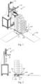
- Fig. 1 is a schematic diagram of an external structure 100 of an item scanning apparatus in an embodiment of the present disclosure
- Fig. 2 is a schematic diagram of an external structure 200 of an item scanning apparatus in an embodiment of the present disclosure.
- the present disclosure provides a scanning apparatus, and the scanning apparatus includes a rotatable rotation component 1 and a scanning device 2, and a positioning device 3.
- the positioning device 3 is configured for positioning the rotation component 1 when the rotation component 1 rotates to different predetermined positions respectively;
- the scanning device 2 is configured for scanning an item placed on the positioned rotation component 1.
- a specific structure of the scanning apparatus is provided.
- the scanning device 2 may scan the rotation component 1 when the rotation component 1 rotates to the different predetermined positions.
- the scanning device 2 may scan different planes of the rotation component 1, and when placing the item, a side of the item on which a serial number is attached is placed at a position where the scanning device 2 can scan.
- the scanning device 2 scans the serial number of the item and enters the serial number into a backend system to complete a task of acceptance and warehousing of the item.
- the item may alternatively be classified by an item code. There may be two situations in the scanning process. If the item code and the serial number of the item are on the same plane, different categories of the item may be placed on the rotation component 1 for scanning. Because in this regard, the scanning device 2 may obtain both the serial number and the item code in the process of scanning the item, the category and the serial number of the item may be identified at the same time.
- the item code and the serial number of the item are not on the same plane, when scanning, it is preferable to scan the serial number, so that the serial number should be preferentially exposed for scanning by the scanning device 2, and only a single category of the item is placed on the rotation component 1, and then the item code of the single category is entered into the backend system.
- the scanning apparatus may alternatively include an operating table, a display component, and a control cabinet.
- the operating table should be arranged with adjustable feet and castors, and the adjustable feet and castors adjust a position of the operating table.
- Fig. 3 is a schematic structural diagram of a rotation component in an embodiment of the present disclosure
- Fig. 4 is a schematic diagram of an external structure 300 of an item scanning apparatus in an embodiment of the present disclosure
- Fig. 5 is a schematic diagram of an external structure 400 of an item scanning apparatus in an embodiment of the present disclosure
- Fig. 6 is an enlarged schematic diagram of a partial structure I of the item scanning apparatus in Fig. 5 of the present disclosure. As shown in Figs. 3 and 4 , and Figs.
- a plurality of positioning marks 13 are arranged at a periphery of a first surface 11 of the rotation component 1 around an axis of a rotation shaft 12 of the rotation component 1, and each of the positioning marks 13 corresponds to one of the predetermined positions, a radial distance between each of the positioning marks 13 and the rotation shaft 12 is L.
- the positioning device 3 is configured to perform a detection on the rotation component 1, a detection position 31 of the positioning device 3 is located on the first surface 11 of the rotation component 1, and a radial distance between the detection position 31 and the rotation shaft 12 is L, so that during the rotation of the rotation component 1, the rotation component 1 is positioned, when the positioning device 3 detects the positioning mark 13 at the detection position
- a specific structure of the rotation component 1 and the positioning device 3 is provided, so that the scanning device 2 may position the item when the item is at different rotation positions on the rotation component 1.
- the different predetermined positions on the rotation component 1 may be marked.
- four sides of the item may be marked as CM1, CM2, CM3, and CM4, respectively, and the four sides are different by 90 degrees.
- CM1 may be used as an initial surface, and after finishing scanning the side of CM1, the scanning device 2 may scan CM2, CM3, and CM4 in sequence.
- the positioning mark 13 is a light-transmitting through hole
- the light-transmitting through hole penetrates the rotation component 1
- the positioning device 3 is a photoelectric sensor
- a probe of the photoelectric sensor faces the detection position 31, so that during the rotation of the rotation component 1, the rotation component 1 is positioned when the probe detects light transmitting through the light-transmitting through hole.
- a specific implementation for detecting through a photoelectric sensor is provided.
- the predetermined position may be one or more.
- four predetermined positions namely CM1, CM2, CM3, and CM4, may be positioned. If the scanning device 2 is arranged at a side of the rotation component 1, then by scanning the above four sides of the rotation component, all the four sides of the item may be scanned.
- the to-be-scanned serial numbers need to be placed at a position on the item where the serial numbers can be displayed. It should be noted that a positional relationship between the rotation component 1 and the scanning device 2 provided in the present embodiment is only to better describe the present embodiment, and is not a limitation to the present embodiment.
- the rotation component 1 may be understood as a turntable.
- the photoelectric sensor calibrates the position of CM1 as an origin position.
- An initial position of the turntable is that the light-transmitting through hole exactly coincides with the center of the photoelectric sensor, and an initial position of the light-transmitting through hole is marked at the same time.
- a motor drives the turntable to automatically rotate. After the turntable rotates automatically, the light-transmitting through hole in the position of CM1 is far away from the photoelectric sensor, and then the photoelectric sensor is blocked by the turntable and obtains a blocking light signal.
- the turntable automatically rotates until a second circular hole coincides with the center of the photoelectric sensor, the photoelectric sensor obtains a relevant signal, then the turntable stops rotating, and starts scanning and collecting the serial number of the item on the side of CM2, and the procedure is repeated until the serial numbers on the sides of CM3 and CM4 are scanned and collected;
- the rotation component 1 includes a rotation part 101 and a power device 102, and the power device 102 drives the rotation part 101 to rotate around the rotation shaft 12 arranged vertically.
- the item is placed on a top surface of the rotation part 101, a bottom surface of the rotation part 101 is the first surface 11 of the rotation component 1, and the probe is arranged close to the first surface 11.
- a specific method for placing item on the rotation part 101 is provided.
- the item is placed on the top of the rotation part 101.
- the rotation part 101 here may alternatively be understood as a turntable.
- the rotation shaft 12 drives the turntable to rotate.
- the rotation shaft 12 being arranged vertically may be understood to ensure that even if the rotation shaft 12 is not perpendicular to the ground or plane on which the scanning device is placed, the item placed on the rotation part 101 may be stably placed on the top of the rotation part 101 during the rotation of the rotation part 101.
- the probe is close to the first surface 11, light cannot enter the photoelectric sensor through the probe.
- the light-transmitting through hole is aligned with the probe, light transmits from the light-transmitting through hole into the photoelectric sensor, and the photoelectric sensor realizes the positioning of the predetermined positions.
- the item is placed on the top surface of the rotation part 101 through an item container 103.
- a limit structure 104 is arranged on at least one side of the top surface of the rotation part 101 for limiting the item container 103.
- a limiting method of the rotation part 101 is provided.
- the item may be placed on the top surface of the rotation part 101 through the item container 103.
- the item container 103 may be understood as a pallet.
- the limit structure 104 may be understood as a barrier arranged along at least one side edge of the pallet. In some embodiments, two corresponding barriers may be arranged on two sides of the top of the rotation part 101, where the two sides are perpendicular to each other.
- two barriers being arranged on the top surface of the top of the rotation part 101 may achieve limiting the pallet in two mutually perpendicular directions, thereby ensuring that not only the item container 103 may be limited during the rotation, but also the item is always stably placed.
- An inner side surface of the limit structure 104 contacting the pallet is a vertical plane, and an outer side surface of the limit structure 104 has an arc shape.
- a slope 105 is arranged at least one side of the rotation part 101, one end of the slope 105 is connected to the top surface of the rotation part 101, and the other end of the slope 105 is in contact with a contact surface on which the rotation part 101 is placed, such that a slope surface is formed.
- the present embodiment provides a specific structure for unloading the pallet on the top of the rotation part 101.
- the pallet may be unloaded from the top of the rotation part 101 to a bottom of the rotation part 101 through the slope 105.
- a weighing device 14 is arranged on the rotation component 1, and the weighing device 14 is configured for weighing the item.
- a weighing apparatus 14 is provided for weighing the item on the rotation component 1 to help record when the item is input into a warehouse.
- the scanning device 2 is arranged at a side of the rotation component 1;
- the scanning device 2 includes a lifting moving device 21 and/or a lateral moving device 22, and a scanning head 23.
- the scanning device 2 includes the lifting moving device 21 or the lateral moving device 22 and the scanning head 23, the scanning head 23 is arranged on the lifting moving device 21 or on the lateral moving device 22.
- the scanning device 2 includes the lifting moving device 21 and the lateral moving device 22, and the scanning head 23, the lateral moving device 22 is arranged on the lifting moving device 21, so that the lifting moving device 21 drives the lateral moving device 22 to move up and down, and the scanning head 23 is arranged on the lateral moving device 22, so that the lateral moving device 22 drives the scanning head to move laterally; and
- the scanning head 23 is directed to a position where the item is placed on the rotation component 1, so as to scan the item; and the scanning head 23 includes an infrared scanning code camera and a radio frequency identification device.
- the number of the scanning heads 23 is plural, and a width of a combined scanning range of the plurality of scanning heads 23 is greater than a width of the item.
- At least one plane of the item placed on the rotation component 1 positioned by the positioning mark 13 is parallel to a plane of a moving direction of the lifting moving device 21 or the lateral moving device 22.
- a plane of the item placed on the rotation component 1 positioned by the positioning mark 13 is parallel to the plane of the moving direction of the lifting moving device 21 or the lateral moving device 22, where the plane of the item faces the scanning head and is closest to the scanning head.
- a specific structure of the scanning device 2 is provided.
- the lifting moving device 21 is supported by a frame. Based on a positional relationship between the item and the rotation component 1 described above, when the scanning device 2 is located at the side of the rotation component 1, the scanning device 2 may scan respective planes of the item.
- the lifting moving device 21 and the lateral moving device 22 may make the scanning head 23 scan a side surface of the rotation component 1 in a plane range and then scan in an area around the item by cooperating with the rotation of the rotation component 1.
- the scanning head 23 may be understood as a camera, and the camera achieves its function by installing auxiliary parts, such as a support and a light source, that is, the camera is configured for automatically collecting and scanning images.
- an embodiment of the present disclosure further provides an item scanning method.
- Fig. 7A shows a schematic diagram of a system structure to which an item scanning method may be applied in an embodiment of the present disclosure.
- the system to which the item scanning method may be applied according to the present disclosure includes at least: a scanning apparatus 11, a network 12, and a server 13.
- the system to which the item scanning method may be applied further includes a handheld device 14 of a staff.
- the scanning apparatus 11 includes the rotatable rotation component 1, the scanning device 2, and the positioning device 3 shown in Figs. 1 and 2 .
- the item may be rotated to the different predetermined positions by the rotation component, the item may be scanned and identified by the scanning device.
- Scanned item information such as an identifier of the item, may be sent to a backend system in the server 11.
- the network 12 may include a wired network and a wireless network. As shown in Fig. 7A , on the access network side, the scanning apparatus 11 and the handheld device 14 may access the network 12 in a wireless approach or in a wired approach; and on the core network side, the server 13 is generally connected to the network 12 in a wired approach. Of course, the server 13 may alternatively be connected to the network 12 in a wireless approach.
- the server 13 is a backend server that records item information.
- the server 13 may receive the item information scanned by the scanning apparatus 11, and may alternatively return the corresponding item information to the handheld device 14 according to a query request from the handheld device 14 of the staff.
- the server 13 may be a single server or a cluster server composed of a plurality of servers.
- the handheld device 14 may refer to a hand-held smart terminal device of an item management staff.
- the handheld device may include, but is not limited to, a smart phone (installed with a communication module), a palmtop computer, a tablet computer, and the like.
- the handheld device 14 has an operating system installed thereon, including but not limited to: Android operating system, Symbian operating system, Windows mobile operating system, Apple iPhone OS operating system, and so on.
- the handheld device 14 generally includes an application client 15 to enable the staff to perform operations such as querying on the item information.
- Fig. 7B is a schematic diagram of a flow 500 of the item scanning method in an embodiment of the present disclosure.
- the method includes: S101, receiving a positioning signal sent by the positioning device 3 when the rotation component 1 rotates to the different predetermined positions.
- the positioning device 3 positions the rotation component 1 when the rotation component rotates to the different predetermined positions.
- the rotation component 1 may define the left and right planes and the front and back planes around the rotation component 1 as the predetermined positions, and one of the planes may be selected as an initial plane.
- the positioning signal is transmitted when the rotation component 1 rotates to the initial plane, the positioning signal is transmitted once every time the rotation component 1 rotates to a next predetermined position, so that the backend system receives positioning signals sent by the positioning device 3.
- the rotation component 1 stops rotating, and an instruction for stopping the rotation of the rotation component 1 may be sent after the backend system receives the positioning signal.
- an instruction interaction may be formed between the positioning device 3 and the rotation component 1, the positioning device 3 sends the positioning signal and the instruction for stopping the rotation of the rotation component 1 at the same time.
- the identification information of different planes at the predetermined positions may be obtained, the identification information being attached to the to-be-scanned item.
- the identification information may be understood as the serial number and/or the item code, the serial number represents a serial number of the item of the warehousing, and the item code is used to identify the category of the to-be-scanned item.
- a specific implementation for scanning the item at the different predetermined positions by the scanning apparatus is provided.
- the positioning device 3 may send the positioning signals.
- the backend system receives the positioning signals, it makes the rotation component 1 stop rotating.
- the scanning device 2 scans the rotation component 1 at the predetermined positions to acquire the identification information, the identification information of the item is attached to the item.
- the identification information may be understood as the serial number and/or the item code, the serial number is used to identify a serial number of the item of the warehousing, and the item code is used to identify the category of the item.
- the scanning device 2 when scanning the item placed on the rotation component 1 by the scanning device 2 according to the scanning instruction to acquire the identification information on the to-be-scanned item, the scanning device 2 may be controlled to scan the item placed on the rotation component 1 according to a first preset scanning path.
- the first preset scanning path includes a plurality of scanning path points, and these scanning path points are preset according to the size of the item.
- the scanning device 2 when controlling the scanning device 2 to scan the item placed on the rotation component 1 according to the first preset scanning path, if the identification information is successfully scanned at a current scanning path point, the scanning device 2 is controlled to move according to the first preset scanning path to a next scanning path point to perform scanning, until the scanning path points on the first preset scanning path are fully scanned; and if the identification information is failed to be scanned at the current scanning path point, information of the current scanning path point is recorded, and the scanning device 2 is controlled to move according to the first preset scanning path to the next scanning path point to perform scanning, until the scanning path points on the first preset scanning path are fully scanned.
- the scanning device 2 may further be controlled to sequentially return to recorded scanning path points where scan of the identification information is failed, and may perform a second scan; and if the second scan is failed, abnormal information may be generated, and the scanning path point where the second scan is failed may be photographed to record an item position corresponding to the scanning path point where the second scan is failed.
- the scanning apparatus may send the generated abnormal information directly to the handheld device of the item management staff, or send the abnormal information to the server, and the server forwards the abnormal information to the handheld device of the item management staff, so that when the staff receives the abnormal information, he may check the item corresponding to the scanning path point where the second scan is failed.
- the rotation component 1 may alternatively be controlled to rotate to a next predetermined position, and perform scanning according to a second preset scanning path, until the item is scanned at the respectively predetermined positions.
- the second preset scanning path may be the same as or different from the first preset scanning path, and may alternatively include a plurality of scanning path points. These scanning path points are preset according to the size of the item.
- each of the predetermined positions corresponds to a preset scanning path, and preset scanning paths may be the same or different.
- the method before the step of receiving a positioning signal sent by the positioning device 3 when the rotation component 1 rotates to the different predetermined positions, the method further includes: entering shelf life information of the to-be-scanned item according to a first predetermined operation of a user.
- a specific implementation for entering the shelf life is provided.
- the user may first call warehousing information of the item, and the user needs to call whether there is a shelf life that needs to be entered from the warehousing information, because one kind of the item does not have a shelf life, or a shelf life is very long such that it may be considered that there is no shelf life, and another kind of the item has a shelf life, so the above two kinds need to be distinguished. If the to-be-scanned item has a shelf life, then the shelf life is entered. Conversely, if the to-be-scanned item does not have a shelf life, a state of no shelf life, i.e., "no shelf life management" is recorded.
- the method before the step of receiving a positioning signal sent by the positioning device 3 when the rotation component 1 rotates to the different predetermined positions, the method further includes: acquiring a rated quantity of the to-be-scanned item according to a second predetermined operation of a user.
- Fig. 8 is a schematic diagram of a flow 600 of the item scanning method in an embodiment of the present disclosure.
- a weighing device 14 is arranged on the rotation component 1, and is configured for weighing the item, and before the step of receiving a positioning signal sent by the positioning device 3 when the rotation component 1 rotates to the different predetermined positions, the method further includes: S201, acquiring a weight of the to-be-scanned item by the weighing device 14;
- the weight of the item is acquired by the weighing device 14.
- S202 calculating an item quantity of the to-be-scanned item based on the weight and a preset single weight of the item;
- the estimated item quantity may be calculated based on the weight and the preset single weight of the item.
- the preset single weight of the item is based on the single weight of one single item of the corresponding to-be-scanned item.
- the item quantity is not an actual quantity of the item, but only a reference quantity calculated for the checking and accepting of the item quantity and for comparison in the subsequent steps.
- Step 203 comparing the item quantity with the rated quantity to obtain a comparison result.
- the item quantity in the previous step is compared with the rated quantity. When the item quantity is less than the rated quantity, it indicates that the actual quantity of the item does not reach the rated quantity, and a stacking quantity of the item may be wrong and need to be checked.
- a specific implementation for checking and accepting the actual quantity of the to-be-scanned item is provided.
- the weight of the to-be-scanned item is acquired by the weighing device 14, the item quantity is calculated based on the weight and the preset single weight of the item, and finally the comparison result is obtained by comparing the item quantity with the rated quantity. Based on the comparison result, it is confirmed whether the stacking quantity of the item is correct.
- the to-be-scanned item is placed on a top surface of the rotation component 1 through the item container 103, before the step of receiving a positioning signal sent by the positioning device 3 when the rotation component 1 rotates to the different predetermined positions, the method further includes: acquiring an item container number of the item container 103 according to a third predetermined operation of a user.
- Fig. 9 is a schematic diagram of a data structure of a warehousing list in the present disclosure. As shown in Fig. 9 , the present embodiment provides a user operation, which enters the item container number of the item container 103 corresponding to the entered serial number and/or the item code of the to-be-scanned item.
- the item may be attached with an identifier, the identifier may be understood as the serial number and/or the item code, the serial number is used to identify the sequence of the item, and the item code is used to identify the category of the item.
- the checking and accepting process of the item is to enter, check and accept the serial number and the item code on each item.
- An operator responsible for checking, accepting and warehousing may log in through the handheld device 14 shown in Fig. 7A .
- a login method may be using an employee account of the operator to log in.
- Warehousing information of the item may be called from a pre-stored data source by scanning a warehousing list code. Scanning the warehousing information may be understood as scanning an identification code on the warehousing information.
- the warehousing information is item information of the item that is distributed in a logistics system.
- the item information includes but is not limited to: a name of the item, an item code, a serial number, whether there is the shelf life (production date, expiration date, shelf life days), an item feature, an item box size and other related information.
- the to-be-scanned items We place the item code of the item on the rotation component 1, where the item code may be scanned in the next step, and items stacked on the rotation component 1 are called the to-be-scanned items. It should be noted that when stacking the to-be-scanned items, the serial numbers attached to the to-be-scanned items should be provided on the outside preferentially to facilitate later scanning. In addition, each warehousing is performed in the form of batches. If to-be-scanned items in a certain batch are excessive, the batch of the excessive to-be-scanned items needs to be separately stacked on the rotation component 1 for several times.
- Fig. 10 is a schematic diagram of a flow 700 of the item scanning method in an embodiment of the present disclosure.
- the scanning method includes: S301, entering shelf life information of the to-be-scanned item according to a first predetermined operation of a user.
- the checking and accepting process in this step since some kinds of the item have no shelf life, such as iron pots, or cups, and some kinds of the item have a shelf life, such as food, it is necessary to enter the shelf life information corresponding to the item in the warehousing information into the relevant content in the checking and accepting process. If there is no management requirement of the shelf life for the accepted item, the description of "no shelf life management" may be directed entered. If the item has a shelf life, the shelf life may be entered.
- Step 302 acquiring a rated quantity of the to-be-scanned item according to a second predetermined operation of a user.
- the user may enter the rated quantity of the to-be-scanned item on the warehousing list into the backend system.
- the rated quantity may be denoted as N1.
- Step 303 acquiring an item container number of the item container 103 according to a third predetermined operation of a user.
- the user may enter the item container numbers. If the to-be-scanned items are stacked through the item containers, the item containers 103 may be understood as pallets. Then, the to-be-scanned item that should be stacked corresponding to each of the item containers 103 may be correspondingly entered, checked and accepted. Then, each of the item containers 103 corresponds to one of the item container numbers, after manually entering the item container numbers, the scanned to-be-scanned items may be correspondingly entered. In addition, this step may alternatively be implemented by scanning the item container numbers attached on the item containers 103. Each of the item containers 103 may be attached with a corresponding unique item container number (for example, a barcode may be used) for scanning.
- a barcode for example, a barcode may be used
- the scanning apparatus may manually use PAD to collect the item container numbers.
- a scanned item container is placed on the top surface of the rotation part 101 and is limited by the limit structure 104.
- the limit structure 104 When the item container is a pallet, two sides of the pallet are respectively pushed on the limit structure 104 to realize limiting.
- Step 304 acquiring a weight of the item by the weighing device; Before this step, it is necessary to confirm a placing approach of the to-be-scanned item on the rotation component 1; If the serial number and the item code of a to-be-scanned item are on the same plane, that is, both may be scanned by the scanning device 2, different categories of the to-be-scanned items may be placed when the to-be-scanned items are placed on the rotation component 1. It is because only when the item codes are scanned, the categories of the to-be-scanned items can be confirmed, and in the above placing approach, the item codes of the to-be-scanned items may be scanned by the scanning device 2, so that the different categories of to-be-scanned items may be placed.
- serial number and the item code of a to-be-scanned item are on different planes, that is, when only the serial numbers of the to-be-scanned items can be scanned by the scanning device 2, it is necessary to only place a single category of the to-be-scanned items when the to-be-scammed items are placed.
- the weight of the placed to-be-scanned items may be obtained by weighing by the weighing device, and the weight is denoted as W. If the item container is used to hold the to-be-scanned item according to the above steps, then a weight of the item container is denoted as W1.
- Step 305 calculating an item quantity based on the weight and a preset single weight of the item;
- the single weight of the to-be-scanned item may be known based on information in the warehousing list, that is, the preset single weight, which is denoted as W2.
- W2 the preset single weight
- the weight of each of the to-be-scanned items is obtained through the warehousing list, or a sum of the weight of each of the to-be-scanned item is divided by the quantity of the to-be-scanned item, which may also be used as the preset single weight for subsequent calculations.
- Step 306 comparing the item quantity with the rated quantity to obtain a comparison result.
- the comparison result in this step is: If the item quantity is less than the rated quantity, it may be understood that the placed to-be-scanned items may be out of stock and do not meet the quantity in the warehousing list, that is, the items are fully checked and accepted. If the item quantity is equal to the rated quantity, it may be understood that the placed to-be-scanned items meet the quantity in the warehousing list, that is, the items are fully checked and accepted.
- Step 307 receiving a positioning signal sent by the positioning device 3 when the rotation component 1 rotates to the different predetermined positions;
- a specific positioning method is provided.
- four sides around the rotation component 1 are respectively understood as four of the predetermined positions of CM1, CM2, CM3, and CM4.
- Step 308 stopping rotating the rotation component 1 according to the positioning signal and generating a scanning instruction; This step provides a specific implementation for stopping rotating the rotation component 1 according to the positioning signal and generating the scanning instruction.
- the scanning head is initialized before scanning.
- the scanning head may be understood as a camera.
- the content of the initialization includes a camera position and focus adjustment, a camera pixel resolution adjustment, a light source brightness and angle adjustment.
- the initialization adjustments are only required for the first boot, and are not required for subsequent collecting serial numbers in a batch.
- an automatic checking and accepting device is started to automatically collect the item serial numbers. First, the device performs an overall scanning on a first plane of CM1, then the device automatically rotates by 90 degrees and performs an overall scanning on a second plane of CM2. The above steps are repeated, until the device completes performing overall scanning on a plane of CM3 and a plane of CM4 in sequence.
- a photo is saved and the predetermined position where the serial number is read and a color (for example, green) are marked; when the serial number is scanned but the information is not read, the saved photo may mark the predetermined position where the serial number is not read, and a color (red).
- a color for example, green
- the scanning device can only identify the serial numbers of respective planes, and save all the serial numbers of the respective planes (CM1, CM2, CM3, CM4) and pictures of the respective planes; when the item code and the serial number of the outer box of the item are on the same plane, multiple categories of the items may be placed.
- the scanning device identifies the item codes and the serial numbers, and at the same time saves all the serial numbers of the respective planes (CM1, CM2, CM3, CM4) and the pictures of the respective planes.
- n N1
- all the serial numbers of the planes of CM1, CM2, CM3, and CM4 are read and marked with the corresponding color (for example, green)
- the serial numbers of the to-be-scanned items in these containers are all checked and accepted.
- the item codes single category or multiple categories
- the serial numbers the total number N1 of the serial numbers
- the above S301 to S307 are repeated to complete the entire checking and accepting process.
- the scanned item codes, the serial numbers, and serial numbers are summarized by performing statistic, including the photos of the four planes (CM1, CM2, CM3, CM4) of each of the item containers 103, all the item container numbers, identity information of the operator, the time stamp, etc.
- Fig. 11 is a schematic diagram of an architecture of an item scanning device in an embodiment of the present disclosure. As shown in Fig. 11 , the present disclosure further provides an item scanning device, and the device includes:
- the scanning module 203 may control the scanning device 2 to scan the item placed on the rotation component 1 according to a first preset scanning path.
- the first preset scanning path includes a plurality of scanning path points, and these scanning path points are preset according to the size of the item.
- the scanning module 203 when controlling the scanning device 2 to scan the item placed on the rotation component 1 according to a first preset scanning path, the scanning module 203 may be configured to: control, if the identification information is successfully scanned at a current scanning path point, the scanning device 2 to move according to the first preset scanning path to a next scanning path point to perform scanning, until the scanning path points on the first preset scanning path are fully scanned; and record, if the identification information is failed to be scanned at the current scanning path point, information of the current scanning path point, and control the scanning device 2 to move according to the first preset scanning path to the next scanning path point to perform scanning, until the scanning path points on the first preset scanning path are fully scanned.
- the scanning module 203 may be further configured to control the scanning device 2 to: sequentially return to recorded scanning path points where scan of the identification information is failed, and to perform a second scan; and generate, if the second scan is failed, abnormal information, and photograph the scanning path point where the second scan is failed to record an item position corresponding to the scanning path point where the second scan is failed.
- the scanning module 203 may be further configured to, send the generated abnormal information directly to the handheld device of the item management staff, or send the abnormal information to the server, and the server forwards the abnormal information to the handheld device of the item management staff, so that when the staff receives the abnormal information, he may check the item corresponding to the scanning path point where the second scan is failed.
- the scanning module 203 may be further configured to, control the rotation component 1 to rotate to a next predetermined position, and perform scanning according to a second preset scanning path, until the item is scanned at the respectively predetermined positions.
- the second preset scanning path may be the same as or different from the first preset scanning path, and may alternatively include a plurality of scanning path points. These scanning path points are preset according to the size of the item.
- each of the predetermined positions corresponds to a preset scanning path, and preset scanning paths may be the same or different.
- the present disclosure further provides an item scanning apparatus, and the apparatus includes: a processor and a memory; and the memory, storing an application program executable by the processor, being configured to cause the processor to perform the steps of the item scanning method.
- FIG. 12 is a hardware structure diagram of an item scanning apparatus in an embodiment of the present disclosure.
- the apparatus includes at least one processor 1201 and a memory 1202 connected to the at least one processor.
- a connection medium between the processor 1201 and the memory 1202 is not limited in the embodiment of the present disclosure.
- the processor 1201 and the memory 1202 are connected through a bus.
- the bus may be classified as an address bus, a data bus, a control bus and so on.
- the memory 1202 stores instructions that can be executed by the at least one processor 1201, and the at least one processor 1201 may perform the steps included in the above item scanning method by executing the instructions stored in the memory 1202.
- the processor 1201 is a control center of the computing device, and may be connected to various parts of a terminal device by using various interfaces and lines. By running or executing the instructions stored in the memory 1202 and calling data stored in the memory 1202, the above item scanning method may be executed.
- the processor 1201 may include one or more processing units, and the processor 1201 may be integrated with an application processor and a modem processor, where the application processor mainly deals with an operating system, a user interface, and the application program, etc., and the modem processor mainly deals with a wireless communication. It may be understood that the modem processor may not be integrated into the processor 1201.
- the processor 1201 and the memory 1202 may be implemented on the same chip, and in some embodiments, they may alternatively be implemented on separate chips.
- the processor 1201 may be a general-purpose processor, such as a central processing unit (CPU), a digital signal processor, an application specific integrated circuit (ASIC), a field programmable gate array or other programmable logic devices, discrete gate or transistor logic devices, discrete hardware components, which may implement or execute the methods, steps, and logic block diagrams disclosed in the embodiments of the present disclosure.
- the general-purpose processor may be a microprocessor or any conventional processor or the like.
- the steps of the method disclosed in the embodiments of the present disclosure may be directly embodied as being executed and completed by a hardware processor, or executed and completed by a combination of hardware and software modules in the processor.
- the memory 1202 may be configured to store non-transitory software programs, non-transitory computer-executable programs and modules.
- the memory 1202 may include at least one type of storage medium, for example, may include flash memory, hard disk, multimedia card, card-type memory, random access memory (RAM), static random access memory (SRAM), programmable read only memory (PROM), read only memory (ROM), electrically erasable programmable read-only memory (EEPROM), magnetic memory, magnetic disk, optical disk, etc.
- the memory 1202 is any other medium that can be used to carry or store desired program codes in the form of instructions or data structures and that can be accessed by the computer, but is not limited thereto.
- the memory 1202 in the embodiment of the present disclosure may alternatively be a circuit or any other apparatus capable of realizing a storage function for storing program instructions and/or data.
- the present disclosure further provides a computer-readable storage medium, storing a computer program thereon, the program, when executed by a processor, implements the steps included in the item scanning method.
- the computer-readable storage medium stores instructions that, when executed by a processor, cause the processor to perform the steps of the method described above.
- the computer-readable medium may be included in the apparatus/device/system described in the above embodiments, or may exist alone without being assembled into the apparatus/device/system.
- the computer-readable storage medium carries one or more programs, and when the one or more programs are executed, the item scanning method is implemented according to the item scanning device described with reference to Fig. 10 .
- the computer readable storage medium may be a non-transitory computer readable storage medium, for example, may include, but is not limited to a portable computer disk, a hard disk, a random access memory (RAM), a read only memory (ROM), an erasable programmable read only memory (EPROM or flash memory), a portable compact disk read only memory (CD-ROM), an optical memory, a magnet memory or any suitable combination of the above, which are not used to limit the protection scope of the present disclosure.
- the computer readable storage medium may be any physical medium containing or storing programs which can be used by or in combination with an instruction execution system, a device or an element.
Landscapes
- Physics & Mathematics (AREA)
- Engineering & Computer Science (AREA)
- Electromagnetism (AREA)
- General Physics & Mathematics (AREA)
- Theoretical Computer Science (AREA)
- General Health & Medical Sciences (AREA)
- Artificial Intelligence (AREA)
- Computer Vision & Pattern Recognition (AREA)
- Toxicology (AREA)
- Health & Medical Sciences (AREA)
- Business, Economics & Management (AREA)
- Economics (AREA)
- Mathematical Physics (AREA)
- Finance (AREA)
- Development Economics (AREA)
- Entrepreneurship & Innovation (AREA)
- Human Resources & Organizations (AREA)
- Marketing (AREA)
- Operations Research (AREA)
- Quality & Reliability (AREA)
- Strategic Management (AREA)
- Tourism & Hospitality (AREA)
- General Business, Economics & Management (AREA)
- Accounting & Taxation (AREA)
Description
- The present disclosure relates to the field of logistics, in particular to a scanning apparatus, a scanning method, a scanning device and a storage medium.
- At present, with the rapid development of e-commerce, the number of item orders has increased geometrically. In the warehousing link of logistics, efficient operations and connections between operation nodes are required. A first node is to put items into warehouses, which is usually managed through the serial numbers of the items. The items to be input into the warehouses are attached with the serial numbers and the serial numbers are scanned one by one, and finally the acceptance and warehousing ofitems are completed.
DocumentWO2010123458 provides an apparatus for acquiring an image of a pallet load. The apparatus operates a line scan camera arranged for movement in a movement plane to acquire the image.
DocumentCN207802110 discloses a full angle image automatic acquisition device, the device can realize 360 degrees controllable automations of object and shoot to obtain the all angles picture of object. Full angle image automatic acquisition device includes supporting part and image acquisition portion, the supporting part with the adjacent setting of image acquisition portion, the supporting part includes the carousel and triggers the portion, image acquisition portion includes image sensor and connects the converter, trigger the portion with the image sensor electricity is connected.
DocumentCN110147692 relates to a group reading and code scanning system for logistics. The system includes a carrier; the rotary stacking table is mounted on the ground on the front side of the carrier; the displacement adjusting mechanism is mounted on the carrier; at least one group reading and code scanning mechanism is arranged, is in transmission connection with the displacement adjusting mechanism and is used for scanning and reading the cargo information bar code information of the logistics packaging box on the rotary stacking platform, and the displacement adjusting mechanism can drive the at least one group reading and code scanning mechanism to move up and down; the control host is electrically connected with the displacement adjusting mechanism and the group reading and code scanning mechanism and used for controlling operation of the displacement adjusting mechanism and the group reading and code scanning mechanism, and the control host is in communication connection with the background data processing terminal. - The invention is set out in the appended set of claims. Although not claimed, the present disclosure provides a scanning apparatus, and the apparatus includes a rotatable rotation component, a scanning device, and a positioning (locating) device.
- The positioning (locating) device is configured for positioning (locating) the rotation component when the rotation component rotates to different predetermined positions respectively, and the scanning device is configured for scanning an item placed on the positioned (located) rotation component.
- In some embodiments, a plurality of positioning (locating) marks is arranged at a periphery of a first surface of the rotation component around an axis of a rotation shaft of the rotation component, and each of the positioning (locating) marks corresponds to one of the predetermined positions, and a radial distance between each of the positioning (locating) marks and the rotation shaft is L.
- The positioning device is configured to perform a detection on the rotation component, a detection position of the positioning (locating) device is located on the first surface of the rotation component, and a radial distance between the detection position and the rotation shaft is L, so that during a rotation of the rotation component, the rotation component is positioned (located) when the positioning (locating) device detects the positioning (locating) mark at the detection position.
- In some embodiments, the positioning (locating) mark is a light-transmitting through hole, the light-transmitting through hole penetrates the rotation component, the positioning (locating) device is a photoelectric sensor, and a probe of the photoelectric sensor faces the detection position, so that during the rotation of the rotation component, the rotation component is positioned when the probe detects light transmitting through the light-transmitting through hole.
- In some embodiments, the rotation component includes a rotation part and a power device, and the power device drives the rotation part to rotate around the rotation shaft arranged vertically.
- The item is placed on a top surface of the rotation part a bottom surface of the rotation part is the first surface of the rotation component, and the probe is arranged close to the first surface.
- In some embodiments, the item is placed on the top surface of the rotation part through an item container.
- A limit structure is arranged on at least one side of the top surface of the rotation part for limiting the item container.
- In some embodiments, a slope is arranged at least one side of the rotation part, where one end of the slope is connected to the top surface of the rotation part, and an other end of the slope is in contact with a contact surface on which the rotation part is placed, such that a slope surface is formed.
- In some embodiments, a weighing device is arranged on the rotation component, and the weighing device is configured for weighing the item.
- In some embodiments, the scanning device is arranged at a side of the rotation component.
- The scanning device includes a lifting moving device and/or a lateral moving device, and a scanning head.
- In some embodiments, the lateral moving device is arranged on the lifting moving device, so that the lifting moving device drives the lateral moving device to move up and down, and the scanning head is arranged on the lateral moving device, so that the lateral moving device drives the scanning head to move laterally.
- The scanning head is directed to a position where the item is placed on the rotation component, so as to scan the item.
- The present disclosure further provides an item scanning method, the method is based on the scanning apparatus, and the method includes:
- receiving a positioning (locating) signal sent by the positioning (locating) device when the rotation component rotates to the different predetermined positions;
- stopping rotating the rotation component according to the positioning (locating) signal and generating a scanning instruction; and
- scanning the item placed on the rotation component by the scanning device according to the scanning instruction to acquire identification information on the to-be-scanned item. This method includes further steps as set out in
claim 1. - In some embodiments, before a step of receiving the positioning signal sent by the positioning device when the rotation component rotates to the different predetermined positions, the method further includes:
entering shelf life information of the to-be-scanned item according to a first predetermined operation of a user. - In some embodiments, before the step of receiving the positioning signal sent by the positioning device when the rotation component rotates to the different predetermined positions, the method further includes:
acquiring a rated quantity of the to-be-scanned item according to a second predetermined operation of a user. - In some embodiments, a weighing device is arranged on the rotation component, and is configured for weighing the to-be-scanned item, and before the step of receiving the positioning signal sent by the positioning device when the rotation component rotates to the different predetermined positions, the method further includes:
- acquiring a weight of the to-be-scanned item by the weighing device;
- calculating an item quantity of the to-be-scanned item based on the weight and a preset single weight of the item; and
- comparing the item quantity with the rated quantity to obtain a comparison result.
- In some embodiments, before the step of acquiring the weight of the to-be-scanned item by the weighing device, the method further includes:
acquiring an item container number of the item container according to a third predetermined operation of a user. - Although not claimed, the present disclosure further provides a scanning device, and the device includes:
- a receiving module, configured to receive a positioning signal sent by the positioning device when the rotation component rotates to the different predetermined positions;
- a generating module, configured to stop rotating the rotation component according to the positioning signal and generate a scanning instruction; and
- a scanning module, configured to scan the to-be-scanned item placed on the rotation component by the scanning device according to the scanning instruction to acquire identification information on the to-be-scanned item.
- Although not claimed, the present disclosure further provides another scanning apparatus, and the apparatus includes: a processor and a memory.
- The memory, storing an application program executable by the processor, is configured to cause the processor to perform the steps of the scanning method.
- The present disclosure further provides a computer-readable storage medium, storing a computer program thereon, and the program, when executed by a scanning apparatus, performs the steps of the scanning method.
-
-
Fig. 1 is a schematic diagram of an external structure 100 of an item scanning apparatus in an embodiment of the present disclosure; -
Fig. 2 is a schematic diagram of an external structure 200 of the item scanning apparatus in an embodiment of the present disclosure; -
Fig. 3 is a schematic structural diagram of a rotation component in an embodiment of the present disclosure; -
Fig. 4 is a schematic diagram of an external structure 300 of the item scanning apparatus in an embodiment of the present disclosure; -
Fig. 5 is a schematic diagram of an external structure 400 of the item scanning apparatus in an embodiment of the present disclosure; -
Fig. 6 is an enlarged schematic diagram of a partial structure I of the item scanning apparatus inFig. 5 of the present disclosure; -
Fig. 7A is a schematic diagram of a system structure to which an item scanning method may be applied in an embodiment of the present disclosure; -
Fig. 7B is a schematic diagram of a flow 500 of the item scanning method in an embodiment of the present disclosure; -
Fig. 8 is a schematic diagram of a flow 600 of the item scanning method in an embodiment of the present disclosure; -
Fig. 9 is a schematic diagram of a data structure of a warehousing list in the present disclosure; -
Fig. 10 is a schematic diagram of a flow 700 of the item scanning method in an embodiment of the present disclosure; -
Fig. 11 is a schematic diagram of an architecture of an item scanning device in an embodiment of the present disclosure; and -
Fig. 12 is a hardware structure diagram of an item scanning apparatus in an embodiment of the present disclosure. -
- 1 Rotation component
- 101 Rotation part
- 102 Power device
- 103 Item container
- 104 Limit structure
- 105 Slope
- 11 First Surface
- 12 Rotation shaft
- 13 Positioning mark
- 14 Weighing device
- 2 Scanning device
- 21 Lifting moving device
- 22 Lateral moving device
- 23 Scanning head
- 3 Positioning device
- 31 Detection position
- 201 Receiving module
- 202 Generating module
- 203 Scanning module
- The following will clearly and completely describe the technical solution in embodiments of the present disclosure in conjunction with the accompanying drawings in the embodiments of the present disclosure. Obviously, the described embodiments are only a part of the embodiments of the present disclosure, rather than all of the embodiments.
- The terms "first", "second", "third", "fourth", etc. (if any) in the specification and claims of the present disclosure and the above accompanying drawings are used to distinguish similar objects, and are not necessarily used to describe a specific order or sequence. It should be understood that the data used in this way may be interchanged under appropriate circumstances, so that the embodiments of the present disclosure described herein, for example, can be implemented in a sequence other than those illustrated or described herein. In addition, the terms "including" and "having", as well as any variations thereof are intended to cover non-exclusive inclusions. For example, processes, methods, systems, products, or apparatuses that include a series of steps or units are not necessarily limited to those clearly listed, but may include those that are not clearly listed, or other steps or units inherent to these processes, methods, products or apparatuses.
- The technical solution of the present disclosure will be described in detail below with reference to the embodiments. The following embodiments may be combined with each other, and same or similar concepts or processes may not be repeated in some embodiments.
- As mentioned above, in the process of item warehousing, it is necessary to scan a serial number attached to an item, which is however generally still completed by manually scanning the serial number. As the quantity of item becomes more and more, the workload in manual mode is gradually increasing and the efficiency is becoming low, which severely restricts the efficiency of an entire logistics supply chain.
- Therefore, the embodiments of the present disclosure propose a scanning apparatus, a scanning method, a scanning device, and a storage medium. An item may be rotated to different predetermined positions by the rotation component, and the item may be scanned and identified by the scanning device, which may improve the efficiency of scanning the item in the process of item warehousing, thereby avoiding the problem of inefficiency in the entire logistics supply chain.
Fig. 1 is a schematic diagram of an external structure 100 of an item scanning apparatus in an embodiment of the present disclosure, andFig. 2 is a schematic diagram of an external structure 200 of an item scanning apparatus in an embodiment of the present disclosure. As shown inFig. 1 and Fig. 2 , in an embodiment, the present disclosure provides a scanning apparatus, and the scanning apparatus includes arotatable rotation component 1 and ascanning device 2, and apositioning device 3. - The
positioning device 3 is configured for positioning therotation component 1 when therotation component 1 rotates to different predetermined positions respectively; and - The
scanning device 2 is configured for scanning an item placed on the positionedrotation component 1. - In the present embodiment, a specific structure of the scanning apparatus is provided. In the process of item warehousing, the item is placed on the
rotation component 1, and thescanning device 2 may scan therotation component 1 when therotation component 1 rotates to the different predetermined positions. - For example, in an item warehousing scenario, the
scanning device 2 may scan different planes of therotation component 1, and when placing the item, a side of the item on which a serial number is attached is placed at a position where thescanning device 2 can scan. Thescanning device 2 scans the serial number of the item and enters the serial number into a backend system to complete a task of acceptance and warehousing of the item. - In addition to the serial number on the item, the item may alternatively be classified by an item code. There may be two situations in the scanning process. If the item code and the serial number of the item are on the same plane, different categories of the item may be placed on the
rotation component 1 for scanning. Because in this regard, thescanning device 2 may obtain both the serial number and the item code in the process of scanning the item, the category and the serial number of the item may be identified at the same time. On the contrary, if the item code and the serial number of the item are not on the same plane, when scanning, it is preferable to scan the serial number, so that the serial number should be preferentially exposed for scanning by thescanning device 2, and only a single category of the item is placed on therotation component 1, and then the item code of the single category is entered into the backend system. - In order to support the specific functions and specific operating environments of the scanning apparatus, the scanning apparatus may alternatively include an operating table, a display component, and a control cabinet. The operating table should be arranged with adjustable feet and castors, and the adjustable feet and castors adjust a position of the operating table.
-
Fig. 3 is a schematic structural diagram of a rotation component in an embodiment of the present disclosure,Fig. 4 is a schematic diagram of an external structure 300 of an item scanning apparatus in an embodiment of the present disclosure,Fig. 5 is a schematic diagram of an external structure 400 of an item scanning apparatus in an embodiment of the present disclosure, andFig. 6 is an enlarged schematic diagram of a partial structure I of the item scanning apparatus inFig. 5 of the present disclosure. As shown inFigs. 3 and 4 , andFigs. 5 and 6 , in an embodiment, a plurality of positioning marks 13 are arranged at a periphery of afirst surface 11 of therotation component 1 around an axis of arotation shaft 12 of therotation component 1, and each of the positioning marks 13 corresponds to one of the predetermined positions, a radial distance between each of the positioning marks 13 and therotation shaft 12 is L. - The
positioning device 3 is configured to perform a detection on therotation component 1, adetection position 31 of thepositioning device 3 is located on thefirst surface 11 of therotation component 1, and a radial distance between thedetection position 31 and therotation shaft 12 is L, so that during the rotation of therotation component 1, therotation component 1 is positioned, when thepositioning device 3 detects thepositioning mark 13 at the detection position - In the present embodiment, a specific structure of the
rotation component 1 and thepositioning device 3 is provided, so that thescanning device 2 may position the item when the item is at different rotation positions on therotation component 1. First, the different predetermined positions on therotation component 1 may be marked. For example, four sides of the item may be marked as CM1, CM2, CM3, and CM4, respectively, and the four sides are different by 90 degrees. CM1 may be used as an initial surface, and after finishing scanning the side of CM1, thescanning device 2 may scan CM2, CM3, and CM4 in sequence. - In an embodiment, the
positioning mark 13 is a light-transmitting through hole, the light-transmitting through hole penetrates therotation component 1, thepositioning device 3 is a photoelectric sensor, and a probe of the photoelectric sensor faces thedetection position 31, so that during the rotation of therotation component 1, therotation component 1 is positioned when the probe detects light transmitting through the light-transmitting through hole. - In the present embodiment, a specific implementation for detecting through a photoelectric sensor is provided. When the probe is aligned with the light-transmitting through hole, external light irradiates to the probe at this time, and then, it is determined that the rotation position of the
rotation component 1 is the predetermined position. Obviously, the predetermined position may be one or more. For example, on the four sides of therotation component 1, four predetermined positions, namely CM1, CM2, CM3, and CM4, may be positioned. If thescanning device 2 is arranged at a side of therotation component 1, then by scanning the above four sides of the rotation component, all the four sides of the item may be scanned. Therefore, when items are stacked, the to-be-scanned serial numbers need to be placed at a position on the item where the serial numbers can be displayed. It should be noted that a positional relationship between therotation component 1 and thescanning device 2 provided in the present embodiment is only to better describe the present embodiment, and is not a limitation to the present embodiment. - The
rotation component 1 may be understood as a turntable. The photoelectric sensor calibrates the position of CM1 as an origin position. An initial position of the turntable is that the light-transmitting through hole exactly coincides with the center of the photoelectric sensor, and an initial position of the light-transmitting through hole is marked at the same time. When the scan of the CM1 side is completed, a motor drives the turntable to automatically rotate. After the turntable rotates automatically, the light-transmitting through hole in the position of CM1 is far away from the photoelectric sensor, and then the photoelectric sensor is blocked by the turntable and obtains a blocking light signal. When the turntable automatically rotates until a second circular hole coincides with the center of the photoelectric sensor, the photoelectric sensor obtains a relevant signal, then the turntable stops rotating, and starts scanning and collecting the serial number of the item on the side of CM2, and the procedure is repeated until the serial numbers on the sides of CM3 and CM4 are scanned and collected; - In an embodiment, the
rotation component 1 includes arotation part 101 and apower device 102, and thepower device 102 drives therotation part 101 to rotate around therotation shaft 12 arranged vertically. - The item is placed on a top surface of the
rotation part 101, a bottom surface of therotation part 101 is thefirst surface 11 of therotation component 1, and the probe is arranged close to thefirst surface 11. - In the present embodiment, a specific method for placing item on the
rotation part 101 is provided. The item is placed on the top of therotation part 101. Therotation part 101 here may alternatively be understood as a turntable. Therotation shaft 12 drives the turntable to rotate. Here, therotation shaft 12 being arranged vertically may be understood to ensure that even if therotation shaft 12 is not perpendicular to the ground or plane on which the scanning device is placed, the item placed on therotation part 101 may be stably placed on the top of therotation part 101 during the rotation of therotation part 101. When the probe is close to thefirst surface 11, light cannot enter the photoelectric sensor through the probe. After therotation part 101 rotates, the light-transmitting through hole is aligned with the probe, light transmits from the light-transmitting through hole into the photoelectric sensor, and the photoelectric sensor realizes the positioning of the predetermined positions. - In an embodiment, the item is placed on the top surface of the
rotation part 101 through anitem container 103. - A
limit structure 104 is arranged on at least one side of the top surface of therotation part 101 for limiting theitem container 103. - In the present embodiment, a limiting method of the
rotation part 101 is provided. The item may be placed on the top surface of therotation part 101 through theitem container 103. Theitem container 103 may be understood as a pallet. When theitem container 103 is configured to hold the item, theitem container 103 needs to be limited relative to therotation part 101. Thelimit structure 104 may be understood as a barrier arranged along at least one side edge of the pallet. In some embodiments, two corresponding barriers may be arranged on two sides of the top of therotation part 101, where the two sides are perpendicular to each other. Since the item should be placed on the top surface of the top of the rotation part 101and the item should not move up and down when therotation part 101 rotates, two barriers being arranged on the top surface of the top of therotation part 101 may achieve limiting the pallet in two mutually perpendicular directions, thereby ensuring that not only theitem container 103 may be limited during the rotation, but also the item is always stably placed. - An inner side surface of the
limit structure 104 contacting the pallet is a vertical plane, and an outer side surface of thelimit structure 104 has an arc shape. - In an embodiment, a
slope 105 is arranged at least one side of therotation part 101, one end of theslope 105 is connected to the top surface of therotation part 101, and the other end of theslope 105 is in contact with a contact surface on which therotation part 101 is placed, such that a slope surface is formed. - The present embodiment provides a specific structure for unloading the pallet on the top of the
rotation part 101. The pallet may be unloaded from the top of therotation part 101 to a bottom of therotation part 101 through theslope 105. - In an embodiment, a weighing
device 14 is arranged on therotation component 1, and the weighingdevice 14 is configured for weighing the item. - In the present embodiment, a weighing
apparatus 14 is provided for weighing the item on therotation component 1 to help record when the item is input into a warehouse. - In an embodiment, the
scanning device 2 is arranged at a side of therotation component 1; and - the
scanning device 2 includes alifting moving device 21 and/or alateral moving device 22, and ascanning head 23. - In some embodiments, if the
scanning device 2 includes thelifting moving device 21 or thelateral moving device 22 and thescanning head 23, thescanning head 23 is arranged on thelifting moving device 21 or on thelateral moving device 22. - In some embodiments, if the
scanning device 2 includes thelifting moving device 21 and thelateral moving device 22, and thescanning head 23, thelateral moving device 22 is arranged on thelifting moving device 21, so that thelifting moving device 21 drives thelateral moving device 22 to move up and down, and thescanning head 23 is arranged on thelateral moving device 22, so that thelateral moving device 22 drives the scanning head to move laterally; and - the
scanning head 23 is directed to a position where the item is placed on therotation component 1, so as to scan the item; and thescanning head 23 includes an infrared scanning code camera and a radio frequency identification device. - In some embodiments, the number of the scanning heads 23 is plural, and a width of a combined scanning range of the plurality of scanning heads 23 is greater than a width of the item.
- In some embodiments, in order to facilitate efficient scanning, after the
positioning mark 13 positions therotation component 1, at least one plane of the item placed on therotation component 1 positioned by thepositioning mark 13 is parallel to a plane of a moving direction of thelifting moving device 21 or thelateral moving device 22. - Specifically, after the
positioning mark 13 positions therotation component 1, a plane of the item placed on therotation component 1 positioned by thepositioning mark 13 is parallel to the plane of the moving direction of thelifting moving device 21 or thelateral moving device 22, where the plane of the item faces the scanning head and is closest to the scanning head. - In the present embodiment, a specific structure of the
scanning device 2 is provided. The lifting movingdevice 21 is supported by a frame. Based on a positional relationship between the item and therotation component 1 described above, when thescanning device 2 is located at the side of therotation component 1, thescanning device 2 may scan respective planes of the item. The lifting movingdevice 21 and thelateral moving device 22 may make thescanning head 23 scan a side surface of therotation component 1 in a plane range and then scan in an area around the item by cooperating with the rotation of therotation component 1. Thescanning head 23 may be understood as a camera, and the camera achieves its function by installing auxiliary parts, such as a support and a light source, that is, the camera is configured for automatically collecting and scanning images. - Corresponding to the scanning apparatus, an embodiment of the present disclosure further provides an item scanning method.
Fig. 7A shows a schematic diagram of a system structure to which an item scanning method may be applied in an embodiment of the present disclosure. As shown inFig. 7A , the system to which the item scanning method may be applied according to the present disclosure includes at least: ascanning apparatus 11, anetwork 12, and aserver 13. In addition, the system to which the item scanning method may be applied further includes ahandheld device 14 of a staff. - In some examples of the present disclosure, the
scanning apparatus 11 includes therotatable rotation component 1, thescanning device 2, and thepositioning device 3 shown inFigs. 1 and 2 . The item may be rotated to the different predetermined positions by the rotation component, the item may be scanned and identified by the scanning device. Scanned item information, such as an identifier of the item, may be sent to a backend system in theserver 11. - The
network 12 may include a wired network and a wireless network. As shown inFig. 7A , on the access network side, thescanning apparatus 11 and thehandheld device 14 may access thenetwork 12 in a wireless approach or in a wired approach; and on the core network side, theserver 13 is generally connected to thenetwork 12 in a wired approach. Of course, theserver 13 may alternatively be connected to thenetwork 12 in a wireless approach. - The
server 13 is a backend server that records item information. Theserver 13 may receive the item information scanned by thescanning apparatus 11, and may alternatively return the corresponding item information to thehandheld device 14 according to a query request from thehandheld device 14 of the staff. Theserver 13 may be a single server or a cluster server composed of a plurality of servers. - The
handheld device 14 may refer to a hand-held smart terminal device of an item management staff. The handheld device may include, but is not limited to, a smart phone (installed with a communication module), a palmtop computer, a tablet computer, and the like. Thehandheld device 14 has an operating system installed thereon, including but not limited to: Android operating system, Symbian operating system, Windows mobile operating system, Apple iPhone OS operating system, and so on. Thehandheld device 14 generally includes anapplication client 15 to enable the staff to perform operations such as querying on the item information. - Based on the above system structure shown in
Fig. 7A , the item scanning method provided by an embodiment of the present disclosure is performed by thescanning apparatus 11 shown inFig. 7A. Fig. 7B is a schematic diagram of a flow 500 of the item scanning method in an embodiment of the present disclosure. As shown inFig. 7B , the method includes:
S101, receiving a positioning signal sent by thepositioning device 3 when therotation component 1 rotates to the different predetermined positions. - In this step, the
positioning device 3 positions therotation component 1 when the rotation component rotates to the different predetermined positions. Therotation component 1 may define the left and right planes and the front and back planes around therotation component 1 as the predetermined positions, and one of the planes may be selected as an initial plane. The positioning signal is transmitted when therotation component 1 rotates to the initial plane, the positioning signal is transmitted once every time therotation component 1 rotates to a next predetermined position, so that the backend system receives positioning signals sent by thepositioning device 3. -
S 102, stopping rotating therotation component 1 according to the positioning signal and generating a scanning instruction. - In this step, when the positioning signal is received, the
rotation component 1 stops rotating, and an instruction for stopping the rotation of therotation component 1 may be sent after the backend system receives the positioning signal. Alternatively, an instruction interaction may be formed between thepositioning device 3 and therotation component 1, thepositioning device 3 sends the positioning signal and the instruction for stopping the rotation of therotation component 1 at the same time. - S103, scanning the item placed on the
rotation component 1 by thescanning device 2 according to the scanning instruction to acquire identification information on the to-be-scanned item. - In this step, a specific implementation for scanning the item placed on the
rotation component 1 is provided. Therotation component 1 at each of the predetermined positions is scanned respectively. Through this step, the identification information of different planes at the predetermined positions may be obtained, the identification information being attached to the to-be-scanned item. The identification information may be understood as the serial number and/or the item code, the serial number represents a serial number of the item of the warehousing, and the item code is used to identify the category of the to-be-scanned item. - In the present embodiment, a specific implementation for scanning the item at the different predetermined positions by the scanning apparatus is provided. Whenever the
rotation component 1 rotates to the different predetermined positions, thepositioning device 3 may send the positioning signals. When the backend system receives the positioning signals, it makes therotation component 1 stop rotating. Then, thescanning device 2 scans therotation component 1 at the predetermined positions to acquire the identification information, the identification information of the item is attached to the item. The identification information may be understood as the serial number and/or the item code, the serial number is used to identify a serial number of the item of the warehousing, and the item code is used to identify the category of the item. - In some embodiments, when scanning the item placed on the
rotation component 1 by thescanning device 2 according to the scanning instruction to acquire the identification information on the to-be-scanned item, thescanning device 2 may be controlled to scan the item placed on therotation component 1 according to a first preset scanning path. - The first preset scanning path includes a plurality of scanning path points, and these scanning path points are preset according to the size of the item.
- In some embodiments, when controlling the
scanning device 2 to scan the item placed on therotation component 1 according to the first preset scanning path, if the identification information is successfully scanned at a current scanning path point, thescanning device 2 is controlled to move according to the first preset scanning path to a next scanning path point to perform scanning, until the scanning path points on the first preset scanning path are fully scanned; and if the identification information is failed to be scanned at the current scanning path point, information of the current scanning path point is recorded, and thescanning device 2 is controlled to move according to the first preset scanning path to the next scanning path point to perform scanning, until the scanning path points on the first preset scanning path are fully scanned. - In some embodiments, after the scanning path points on the first preset scanning path are fully scanned, the
scanning device 2 may further be controlled to sequentially return to recorded scanning path points where scan of the identification information is failed, and may perform a second scan; and if the second scan is failed, abnormal information may be generated, and the scanning path point where the second scan is failed may be photographed to record an item position corresponding to the scanning path point where the second scan is failed. - In some embodiments, the scanning apparatus may send the generated abnormal information directly to the handheld device of the item management staff, or send the abnormal information to the server, and the server forwards the abnormal information to the handheld device of the item management staff, so that when the staff receives the abnormal information, he may check the item corresponding to the scanning path point where the second scan is failed.
- In some embodiments, after completing the second scan of the recorded scanning path points where the scan is failed, the
rotation component 1 may alternatively be controlled to rotate to a next predetermined position, and perform scanning according to a second preset scanning path, until the item is scanned at the respectively predetermined positions. - The second preset scanning path may be the same as or different from the first preset scanning path, and may alternatively include a plurality of scanning path points. These scanning path points are preset according to the size of the item.
- In some embodiments, each of the predetermined positions corresponds to a preset scanning path, and preset scanning paths may be the same or different.
- In an embodiment, before the step of receiving a positioning signal sent by the
positioning device 3 when therotation component 1 rotates to the different predetermined positions, the method further includes:
entering shelf life information of the to-be-scanned item according to a first predetermined operation of a user. - In the present embodiment, a specific implementation for entering the shelf life is provided. In the process of warehousing of the to-be-scanned item, the user may first call warehousing information of the item, and the user needs to call whether there is a shelf life that needs to be entered from the warehousing information, because one kind of the item does not have a shelf life, or a shelf life is very long such that it may be considered that there is no shelf life, and another kind of the item has a shelf life, so the above two kinds need to be distinguished. If the to-be-scanned item has a shelf life, then the shelf life is entered. Conversely, if the to-be-scanned item does not have a shelf life, a state of no shelf life, i.e., "no shelf life management" is recorded.
- In an embodiment, before the step of receiving a positioning signal sent by the
positioning device 3 when therotation component 1 rotates to the different predetermined positions, the method further includes:
acquiring a rated quantity of the to-be-scanned item according to a second predetermined operation of a user. - In the present embodiment, a specific implementation in which the user may enter the rated quantity of the to-be-scanned item into the warehousing information is provided.
-
Fig. 8 is a schematic diagram of a flow 600 of the item scanning method in an embodiment of the present disclosure. As shown inFig. 8 , in an embodiment, a weighingdevice 14 is arranged on therotation component 1, and is configured for weighing the item, and before the step of receiving a positioning signal sent by thepositioning device 3 when therotation component 1 rotates to the different predetermined positions, the method further includes:
S201, acquiring a weight of the to-be-scanned item by the weighingdevice 14; - In this step, the weight of the item is acquired by the weighing
device 14. - S202, calculating an item quantity of the to-be-scanned item based on the weight and a preset single weight of the item;
In this step, a specific implementation for calculating the item quantity is provided, and the estimated item quantity may be calculated based on the weight and the preset single weight of the item. It should be noted that the preset single weight of the item is based on the single weight of one single item of the corresponding to-be-scanned item. In addition, the item quantity is not an actual quantity of the item, but only a reference quantity calculated for the checking and accepting of the item quantity and for comparison in the subsequent steps. -
Step 203, comparing the item quantity with the rated quantity to obtain a comparison result. - The item quantity in the previous step is compared with the rated quantity. When the item quantity is less than the rated quantity, it indicates that the actual quantity of the item does not reach the rated quantity, and a stacking quantity of the item may be wrong and need to be checked.
- In the present embodiment, a specific implementation for checking and accepting the actual quantity of the to-be-scanned item is provided. The weight of the to-be-scanned item is acquired by the weighing
device 14, the item quantity is calculated based on the weight and the preset single weight of the item, and finally the comparison result is obtained by comparing the item quantity with the rated quantity. Based on the comparison result, it is confirmed whether the stacking quantity of the item is correct. - In an embodiment, the to-be-scanned item is placed on a top surface of the
rotation component 1 through theitem container 103, before the step of receiving a positioning signal sent by thepositioning device 3 when therotation component 1 rotates to the different predetermined positions, the method further includes:
acquiring an item container number of theitem container 103 according to a third predetermined operation of a user. -
Fig. 9 is a schematic diagram of a data structure of a warehousing list in the present disclosure. As shown inFig. 9 , the present embodiment provides a user operation, which enters the item container number of theitem container 103 corresponding to the entered serial number and/or the item code of the to-be-scanned item. - In the following, the technical solution of the present disclosure will be further described by taking the process of checking, accepting and warehousing of item as an example. It should be noted that the process of checking, accepting and warehousing of the item is only to better describe the present disclosure, rather than a limitation to the present disclosure.
- In the process of checking, accepting and warehousing of the item, the item may be attached with an identifier, the identifier may be understood as the serial number and/or the item code, the serial number is used to identify the sequence of the item, and the item code is used to identify the category of the item. The checking and accepting process of the item is to enter, check and accept the serial number and the item code on each item.
- An operator responsible for checking, accepting and warehousing may log in through the
handheld device 14 shown inFig. 7A . A login method may be using an employee account of the operator to log in. Warehousing information of the item may be called from a pre-stored data source by scanning a warehousing list code. Scanning the warehousing information may be understood as scanning an identification code on the warehousing information. The warehousing information is item information of the item that is distributed in a logistics system. The item information includes but is not limited to: a name of the item, an item code, a serial number, whether there is the shelf life (production date, expiration date, shelf life days), an item feature, an item box size and other related information. We place the item code of the item on therotation component 1, where the item code may be scanned in the next step, and items stacked on therotation component 1 are called the to-be-scanned items. It should be noted that when stacking the to-be-scanned items, the serial numbers attached to the to-be-scanned items should be provided on the outside preferentially to facilitate later scanning. In addition, each warehousing is performed in the form of batches. If to-be-scanned items in a certain batch are excessive, the batch of the excessive to-be-scanned items needs to be separately stacked on therotation component 1 for several times. - Based on the above scanning apparatus, the scanning method corresponding to the scanning apparatus includes:
Fig. 10 is a schematic diagram of a flow 700 of the item scanning method in an embodiment of the present disclosure. - As shown in
Fig. 10 , in an embodiment, the scanning method includes:
S301, entering shelf life information of the to-be-scanned item according to a first predetermined operation of a user. - In the checking and accepting process in this step, since some kinds of the item have no shelf life, such as iron pots, or cups, and some kinds of the item have a shelf life, such as food, it is necessary to enter the shelf life information corresponding to the item in the warehousing information into the relevant content in the checking and accepting process. If there is no management requirement of the shelf life for the accepted item, the description of "no shelf life management" may be directed entered. If the item has a shelf life, the shelf life may be entered.
- Step 302, acquiring a rated quantity of the to-be-scanned item according to a second predetermined operation of a user.
- In this step, the user may enter the rated quantity of the to-be-scanned item on the warehousing list into the backend system. The rated quantity may be denoted as N1.
- Step 303, acquiring an item container number of the
item container 103 according to a third predetermined operation of a user. - In this step, the user may enter the item container numbers. If the to-be-scanned items are stacked through the item containers, the
item containers 103 may be understood as pallets. Then, the to-be-scanned item that should be stacked corresponding to each of theitem containers 103 may be correspondingly entered, checked and accepted. Then, each of theitem containers 103 corresponds to one of the item container numbers, after manually entering the item container numbers, the scanned to-be-scanned items may be correspondingly entered. In addition, this step may alternatively be implemented by scanning the item container numbers attached on theitem containers 103. Each of theitem containers 103 may be attached with a corresponding unique item container number (for example, a barcode may be used) for scanning. The scanning apparatus may manually use PAD to collect the item container numbers. A scanned item container is placed on the top surface of therotation part 101 and is limited by thelimit structure 104. When the item container is a pallet, two sides of the pallet are respectively pushed on thelimit structure 104 to realize limiting. - Step 304, acquiring a weight of the item by the weighing device;
Before this step, it is necessary to confirm a placing approach of the to-be-scanned item on therotation component 1;
If the serial number and the item code of a to-be-scanned item are on the same plane, that is, both may be scanned by thescanning device 2, different categories of the to-be-scanned items may be placed when the to-be-scanned items are placed on therotation component 1. It is because only when the item codes are scanned, the categories of the to-be-scanned items can be confirmed, and in the above placing approach, the item codes of the to-be-scanned items may be scanned by thescanning device 2, so that the different categories of to-be-scanned items may be placed. - If the serial number and the item code of a to-be-scanned item are on different planes, that is, when only the serial numbers of the to-be-scanned items can be scanned by the
scanning device 2, it is necessary to only place a single category of the to-be-scanned items when the to-be-scammed items are placed. - After placing the to-be-scanned item according to the above approach, the weight of the placed to-be-scanned items may be obtained by weighing by the weighing device, and the weight is denoted as W. If the item container is used to hold the to-be-scanned item according to the above steps, then a weight of the item container is denoted as W1.
-
Step 305, calculating an item quantity based on the weight and a preset single weight of the item;
In this regard, if the to-be-scanned item are a single item, the single weight of the to-be-scanned item may be known based on information in the warehousing list, that is, the preset single weight, which is denoted as W2. Even if the placed to-be-scanned items are not a single item, an average weight of the to-be-scanned items may be used as the preset single weight. The weight of each of the to-be-scanned items is obtained through the warehousing list, or a sum of the weight of each of the to-be-scanned item is divided by the quantity of the to-be-scanned item, which may also be used as the preset single weight for subsequent calculations. The item quantity is calculated according to the formula n=(W-W1)/W2. - Step 306, comparing the item quantity with the rated quantity to obtain a comparison result.
- The comparison result in this step is:
If the item quantity is less than the rated quantity, it may be understood that the placed to-be-scanned items may be out of stock and do not meet the quantity in the warehousing list, that is, the items are fully checked and accepted. If the item quantity is equal to the rated quantity, it may be understood that the placed to-be-scanned items meet the quantity in the warehousing list, that is, the items are fully checked and accepted. - Step 307, receiving a positioning signal sent by the
positioning device 3 when therotation component 1 rotates to the different predetermined positions;
In this step, a specific positioning method is provided. For example, four sides around therotation component 1 are respectively understood as four of the predetermined positions of CM1, CM2, CM3, and CM4. -
Step 308, stopping rotating therotation component 1 according to the positioning signal and generating a scanning instruction;
This step provides a specific implementation for stopping rotating therotation component 1 according to the positioning signal and generating the scanning instruction. - S309, scanning the item placed on the rotation component by the scanning device according to the scanning instruction to acquire identification information on the item.
- In this step, a specific implementation for scanning the identification information is provided. The scanning head is initialized before scanning. The scanning head may be understood as a camera. The content of the initialization includes a camera position and focus adjustment, a camera pixel resolution adjustment, a light source brightness and angle adjustment. When using in a batch, the initialization adjustments are only required for the first boot, and are not required for subsequent collecting serial numbers in a batch.
- Automatic checking, accepting and collecting of item serial numbers: an automatic checking and accepting device is started to automatically collect the item serial numbers. First, the device performs an overall scanning on a first plane of CM1, then the device automatically rotates by 90 degrees and performs an overall scanning on a second plane of CM2. The above steps are repeated, until the device completes performing overall scanning on a plane of CM3 and a plane of CM4 in sequence.
- When the serial number is scanned and serial number information is read at the same time, a photo is saved and the predetermined position where the serial number is read and a color (for example, green) are marked; when the serial number is scanned but the information is not read, the saved photo may mark the predetermined position where the serial number is not read, and a color (red).
- When the item code and the serial number of an outer box of the item are not on the same plane, a single category of the item is placed. The scanning device can only identify the serial numbers of respective planes, and save all the serial numbers of the respective planes (CM1, CM2, CM3, CM4) and pictures of the respective planes;
when the item code and the serial number of the outer box of the item are on the same plane, multiple categories of the items may be placed. The scanning device identifies the item codes and the serial numbers, and at the same time saves all the serial numbers of the respective planes (CM1, CM2, CM3, CM4) and the pictures of the respective planes. - If the comparison result is that all items are checked and accepted, n=N1, and at the same time, all the serial numbers of the planes of CM1, CM2, CM3, and CM4 are read and marked with the corresponding color (for example, green), the serial numbers of the to-be-scanned items in these containers are all checked and accepted. At the same time, the item codes (single category or multiple categories), the serial numbers, the total number N1 of the serial numbers, the photos of the four planes (CM1, CM2, CM3, CM4), the container numbers, the operators, a time stamps and other information read in these containers are saved.
- Not all items are checked and accepted: when n≠N1 or the photos of the planes of CM1, CM2, CM3, CM4 show that there is a unread serial number, for an item with the unread serial number, the automatic checking and accepting device is restarted to collect the serial number, or a manual collection (PDA scanning or manual inputting the serial number of the item) is performed on the item whose serial number is collected , until all the serial numbers of the items in these container are checked and accepted.
- The above S301 to S307 are repeated to complete the entire checking and accepting process. The scanned item codes, the serial numbers, and serial numbers are summarized by performing statistic, including the photos of the four planes (CM1, CM2, CM3, CM4) of each of the
item containers 103, all the item container numbers, identity information of the operator, the time stamp, etc. -
Fig. 11 is a schematic diagram of an architecture of an item scanning device in an embodiment of the present disclosure. As shown inFig. 11 , the present disclosure further provides an item scanning device, and the device includes: - a
receiving module 201, configured to receive a positioning signal sent by thepositioning device 3 when therotation component 1 rotates to the different predetermined positions; - a
generating module 202, configured to stop rotating therotation component 1 according to the positioning signal and generate a scanning instruction; and - a
scanning module 203, configured to scan the to-be-scanned item placed on therotation component 1 by thescanning device 2 according to the scanning instruction to acquire identification information on the to-be-scanned item. - In some embodiments, when scanning the to-be-scanned item placed on the
rotation component 1 by thescanning device 2 according to the scanning instruction to acquire the identification information on the to-be-scanned item, thescanning module 203 may control thescanning device 2 to scan the item placed on therotation component 1 according to a first preset scanning path. The first preset scanning path includes a plurality of scanning path points, and these scanning path points are preset according to the size of the item. - In some embodiments, when controlling the
scanning device 2 to scan the item placed on therotation component 1 according to a first preset scanning path, thescanning module 203 may be configured to: control, if the identification information is successfully scanned at a current scanning path point, thescanning device 2 to move according to the first preset scanning path to a next scanning path point to perform scanning, until the scanning path points on the first preset scanning path are fully scanned; and record, if the identification information is failed to be scanned at the current scanning path point, information of the current scanning path point, and control thescanning device 2 to move according to the first preset scanning path to the next scanning path point to perform scanning, until the scanning path points on the first preset scanning path are fully scanned. - In some embodiments, after the scanning path points on the first preset scanning path are fully scanned, the
scanning module 203 may be further configured to control thescanning device 2 to: sequentially return to recorded scanning path points where scan of the identification information is failed, and to perform a second scan; and generate, if the second scan is failed, abnormal information, and photograph the scanning path point where the second scan is failed to record an item position corresponding to the scanning path point where the second scan is failed. - In some embodiments, the
scanning module 203 may be further configured to, send the generated abnormal information directly to the handheld device of the item management staff, or send the abnormal information to the server, and the server forwards the abnormal information to the handheld device of the item management staff, so that when the staff receives the abnormal information, he may check the item corresponding to the scanning path point where the second scan is failed. - In some embodiments, after completing the second scan of the recorded scanning path points where the scan is failed, the
scanning module 203 may be further configured to, control therotation component 1 to rotate to a next predetermined position, and perform scanning according to a second preset scanning path, until the item is scanned at the respectively predetermined positions. - The second preset scanning path may be the same as or different from the first preset scanning path, and may alternatively include a plurality of scanning path points. These scanning path points are preset according to the size of the item.
- In some embodiments, each of the predetermined positions corresponds to a preset scanning path, and preset scanning paths may be the same or different.
- The present disclosure further provides an item scanning apparatus, and the apparatus includes: a processor and a memory; and
the memory, storing an application program executable by the processor, being configured to cause the processor to perform the steps of the item scanning method. - Based on the same technical concept, an embodiment of the present disclosure further provides a scanning apparatus.
Fig. 12 is a hardware structure diagram of an item scanning apparatus in an embodiment of the present disclosure. As shown inFig. 12 , the apparatus includes at least oneprocessor 1201 and amemory 1202 connected to the at least one processor. A connection medium between theprocessor 1201 and thememory 1202 is not limited in the embodiment of the present disclosure. InFig. 12 , as an example, theprocessor 1201 and thememory 1202 are connected through a bus. The bus may be classified as an address bus, a data bus, a control bus and so on. - In an embodiment of the present disclosure, the
memory 1202 stores instructions that can be executed by the at least oneprocessor 1201, and the at least oneprocessor 1201 may perform the steps included in the above item scanning method by executing the instructions stored in thememory 1202. - The
processor 1201 is a control center of the computing device, and may be connected to various parts of a terminal device by using various interfaces and lines. By running or executing the instructions stored in thememory 1202 and calling data stored in thememory 1202, the above item scanning method may be executed. In some embodiments, theprocessor 1201 may include one or more processing units, and theprocessor 1201 may be integrated with an application processor and a modem processor, where the application processor mainly deals with an operating system, a user interface, and the application program, etc., and the modem processor mainly deals with a wireless communication. It may be understood that the modem processor may not be integrated into theprocessor 1201. In some embodiments, theprocessor 1201 and thememory 1202 may be implemented on the same chip, and in some embodiments, they may alternatively be implemented on separate chips. - The
processor 1201 may be a general-purpose processor, such as a central processing unit (CPU), a digital signal processor, an application specific integrated circuit (ASIC), a field programmable gate array or other programmable logic devices, discrete gate or transistor logic devices, discrete hardware components, which may implement or execute the methods, steps, and logic block diagrams disclosed in the embodiments of the present disclosure. The general-purpose processor may be a microprocessor or any conventional processor or the like. The steps of the method disclosed in the embodiments of the present disclosure may be directly embodied as being executed and completed by a hardware processor, or executed and completed by a combination of hardware and software modules in the processor. - The
memory 1202, as a non-transitory computer-readable storage medium, may be configured to store non-transitory software programs, non-transitory computer-executable programs and modules. Thememory 1202 may include at least one type of storage medium, for example, may include flash memory, hard disk, multimedia card, card-type memory, random access memory (RAM), static random access memory (SRAM), programmable read only memory (PROM), read only memory (ROM), electrically erasable programmable read-only memory (EEPROM), magnetic memory, magnetic disk, optical disk, etc. Thememory 1202 is any other medium that can be used to carry or store desired program codes in the form of instructions or data structures and that can be accessed by the computer, but is not limited thereto. Thememory 1202 in the embodiment of the present disclosure may alternatively be a circuit or any other apparatus capable of realizing a storage function for storing program instructions and/or data. - Therefore, the present disclosure further provides a computer-readable storage medium, storing a computer program thereon, the program, when executed by a processor, implements the steps included in the item scanning method.
- The computer-readable storage medium stores instructions that, when executed by a processor, cause the processor to perform the steps of the method described above. In practical applications, the computer-readable medium may be included in the apparatus/device/system described in the above embodiments, or may exist alone without being assembled into the apparatus/device/system. The computer-readable storage medium carries one or more programs, and when the one or more programs are executed, the item scanning method is implemented according to the item scanning device described with reference to
Fig. 10 . - According to the embodiments of the present disclosure, the computer readable storage medium may be a non-transitory computer readable storage medium, for example, may include, but is not limited to a portable computer disk, a hard disk, a random access memory (RAM), a read only memory (ROM), an erasable programmable read only memory (EPROM or flash memory), a portable compact disk read only memory (CD-ROM), an optical memory, a magnet memory or any suitable combination of the above, which are not used to limit the protection scope of the present disclosure. In the embodiments of the present disclosure, the computer readable storage medium may be any physical medium containing or storing programs which can be used by or in combination with an instruction execution system, a device or an element.
- It should be appreciated by those skilled in the art that various combinations of features recited in various embodiments and/or the claims of the present disclosure may be made even if such combinations are not expressly recited in the present disclosure. In particular, various combinations of features recited in various embodiments and/or the claims of the present disclosure may be made without departing from the teachings of the present disclosure, and all of such combinations fall within the scope of the present disclosure.
- The principles and embodiments of the present disclosure are described with reference to specific embodiments herein, and the description of the embodiments is merely used to facilitate understanding of the method of the present disclosure and core thoughts of the present disclosure, and is not intended to limit the present disclosure.
Claims (10)
- A scanning method, executed by a scanning apparatus, the scanning apparatus comprising a rotatable rotation component (1) and a scanning device (2), and a locating device, wherein: the locating device (3) is configured for locating the rotation component (1) when the rotation component rotates to different predetermined positions respectively, and the scanning device (2) is configured for scanning an item placed on the located rotation component (1), wherein the method comprises:receiving (S101) a locating signal sent by the locating device (3) when the rotation component (1) rotates to the different predetermined positions;stopping (s102) rotating the rotation component (1) according to the locating signal and generating a scanning instruction; andscanning (s103) the item placed on the rotation component (1) by the scanning device (2) according to the scanning instruction to acquire identification information on the to-be-scanned item;wherein, the scanning the item placed on the rotation component (1) by the scanning device (2) according to the scanning instruction to acquire identification information on the to-be-scanned item, comprises:controlling the scanning device (2) to scan the item placed on the rotation component (1) according to a first preset scanning path;wherein the first preset scanning path comprises a plurality of scanning path points;wherein, the controlling the scanning device (2) to scan the item placed on the rotation component (1) according to a first preset scanning path, comprises:controlling, in response to successfully scanning the identification information at a current scanning path point, the scanning device (2) to move according to the first preset scanning path to a next scanning path point to perform scanning, until the scanning path points on the first preset scanning path are fully scanned; andrecording, in response to failing to scan the identification information at the current scanning path point, information of the current scanning path point, and controlling the scanning device (2) to move according to the first preset scanning path to the next scanning path point to perform scanning, until the scanning path points on the first preset scanning path are fully scanned;wherein, after the scanning path points on the first preset scanning path are fully scanned, the method further comprises:controlling the scanning device (2) to sequentially return to recorded scanning path points where scan of the identification information has failed, and performing a second scan; andgenerating, in response to the second scan failing to scan the identification information, abnormal information, and photographing the scanning path point where the second scan has 4 failed, to record an item position corresponding to the scanning path point where the second scan has failed.
- The scanning method according to claim 1, wherein, after completing the second scan of the recorded scanning path points where the scan has failed, the method further comprises:
controlling the rotation component (1) to rotate to a next predetermined position, and performing scanning according to a second preset scanning path. - The scanning method according to any one of claims 1 to 2, wherein, a weighing device (14) is arranged on the rotation component (1), and is configured for weighing the to-be-scanned item, and before the step of receiving the locating signal sent by the locating device (3) when the rotation component (1) rotates to the different predetermined positions, the method further comprises:acquiring (s201) a weight of the to-be-scanned item by the weighing device (14);calculating (s202) an item quantity of the to-be-scanned item based on the weight and a preset single weight of the item; andcomparing (s203) the item quantity with the rated quantity to obtain a comparison result.
- The scanning method according to any one of claims 1 to 3, wherein a plurality of locating marks (13) are arranged at a periphery of a first surface (11) of the rotation component (1) around an axis of a rotation shaft (12) of the rotation component (1), and each of the locating marks (13) corresponds to one of the predetermined positions, and a radial distance between each of the locating marks (13) and the rotation shaft (12) is L; wherein the locating device (3) is configured to perform a detection on the rotation component (1), a detection position (31) of the locating device (3) is located on the first surface (11) of the rotation component (1), and a radial distance between the detection position (31) and the rotation shaft (12) is L, so that during a rotation of the rotation component (1), the rotation component (1) is located when the locating device (3) detects the locating mark (13) at the detection position (31).
- The scanning method according to claim 4, wherein, the locating mark (13) is a light-transmitting through hole, the light-transmitting through hole penetrates the rotation component (1), the locating device (3) is a photoelectric sensor, and a probe of the photoelectric sensor faces the detection position (31), so that during the rotation of the rotation component (1), the rotation component (1) is positioned when the probe detects light transmitting through the light-transmitting through hole.
- The scanning method according to any one of claims 1 to 5, wherein, a or the weighing device (14) is arranged on the rotation component (1), and the weighing device (14) is configured for weighing the item.
- The scanning method according to any one of claims 4 to 6, wherein, the scanning device (2) is arranged at a side of the rotation component (1); and
the scanning device (2) comprises a lifting moving device (21) and/or a lateral moving device (22), and a scanning head (23). - The scanning method according to claim 7, wherein, if the scanning device (2) comprises the lifting moving device (21) and the lateral moving device (22), and the scanning head (23), the lateral moving device (22) is arranged on the lifting moving device (21), so that the lifting moving device (21) drives the lateral moving device (22) to move up and down, and the scanning head (23) is arranged on the lateral moving device (22), so that the lateral moving device (22) drives the scanning head to move laterally; and
the scanning head (23) is directed to a position where the item is placed on the rotation component (1), so as to scan the item. - The scanning method according to claim 7 or 8, wherein, after the locating mark (13) positions the rotation component (1), at least one plane of the item placed on the rotation component (1) positioned by the locating mark (13) is parallel to a plane of a moving direction of the lifting moving device (21) or the lateral moving device (22).
- A computer-readable storage medium, storing a computer program thereon, wherein the program, when executed by a scanning apparatus, implements steps of the scanning method according to any one of claims 1 to 9.
Applications Claiming Priority (2)
| Application Number | Priority Date | Filing Date | Title |
|---|---|---|---|
| CN201910850987.9A CN110598496A (en) | 2019-09-10 | 2019-09-10 | Scanning device, method, device and storage medium thereof |
| PCT/CN2020/080784 WO2021047164A1 (en) | 2019-09-10 | 2020-03-24 | Scanning equipment, method, device, and storage medium |
Publications (4)
| Publication Number | Publication Date |
|---|---|
| EP3989103A1 EP3989103A1 (en) | 2022-04-27 |
| EP3989103A4 EP3989103A4 (en) | 2023-07-05 |
| EP3989103C0 EP3989103C0 (en) | 2024-11-06 |
| EP3989103B1 true EP3989103B1 (en) | 2024-11-06 |
Family
ID=68858406
Family Applications (1)
| Application Number | Title | Priority Date | Filing Date |
|---|---|---|---|
| EP20863865.0A Active EP3989103B1 (en) | 2019-09-10 | 2020-03-24 | Scanning equipment, method, device, and storage medium |
Country Status (4)
| Country | Link |
|---|---|
| US (1) | US11928547B2 (en) |
| EP (1) | EP3989103B1 (en) |
| CN (1) | CN110598496A (en) |
| WO (1) | WO2021047164A1 (en) |
Families Citing this family (5)
| Publication number | Priority date | Publication date | Assignee | Title |
|---|---|---|---|---|
| CN110598496A (en) * | 2019-09-10 | 2019-12-20 | 北京京东振世信息技术有限公司 | Scanning device, method, device and storage medium thereof |
| CN112488093B (en) * | 2020-11-25 | 2023-03-31 | 西北工业大学 | Part identification data set collection system |
| CN113697458A (en) * | 2021-09-28 | 2021-11-26 | 福建省鸿林物流有限公司 | Logistics transfer warehousing system and method thereof |
| CN114966071B (en) * | 2022-08-02 | 2023-05-09 | 长春东元生物技术有限公司 | Shipping Scanning Structures, Shipping Methods, Sample Analyzers, and Troubleshooting Methods |
| CN116321268B (en) * | 2023-03-06 | 2023-11-03 | 乾位智通(深圳)技术有限公司 | Detection data recording system, method and device and UWB module detection device |
Family Cites Families (19)
| Publication number | Priority date | Publication date | Assignee | Title |
|---|---|---|---|---|
| JP3586583B2 (en) | 1999-05-10 | 2004-11-10 | 日本電気エンジニアリング株式会社 | Barcode reader |
| WO2010123458A1 (en) | 2009-04-30 | 2010-10-28 | Azimuth Intellectual Products Pte Ltd | Apparatus and method for acquiring an image of a pallet load |
| CN203199637U (en) * | 2013-03-28 | 2013-09-18 | 浙江久而久化学有限公司 | Full-automatic rotary table conveying device |
| CN103692213B (en) * | 2013-12-26 | 2017-03-22 | 浙江宇视科技有限公司 | Circular no-power-down assembly line |
| US20160171267A1 (en) * | 2014-12-10 | 2016-06-16 | Fu Tai Hua Industry (Shenzhen) Co., Ltd. | Scanning device |
| US10002377B1 (en) * | 2014-12-22 | 2018-06-19 | Amazon Technologies, Inc. | Infrared driven item recommendations |
| CN204872792U (en) * | 2015-07-23 | 2015-12-16 | 苏州宏瑞达新能源装备有限公司 | Horizontal rotation device based on light sense control rotation angle |
| US10268860B2 (en) | 2016-12-22 | 2019-04-23 | Datalogic ADC, Inc. | White illumination for barcode scanners with improved power efficiency and cost |
| CN107008656A (en) * | 2017-05-26 | 2017-08-04 | 杭州汉风电气有限公司 | A kind of combined type express delivery sorting machine people and method for sorting |
| CN207802110U (en) * | 2017-09-27 | 2018-08-31 | 中山市宾哥网络科技有限公司 | All-angle image automatic acquisition device |
| CN107451503A (en) * | 2017-09-29 | 2017-12-08 | 北京施塔尔科技有限公司 | A kind of rotation barcode scanning device for heparin tube |
| JP7195565B2 (en) * | 2017-12-28 | 2022-12-26 | 伊東電機株式会社 | Code reading device and code reading method |
| US12211076B2 (en) * | 2018-01-24 | 2025-01-28 | Nike, Inc. | System, platform and method for personalized shopping using a virtual shopping assistant |
| US10782118B2 (en) * | 2018-02-21 | 2020-09-22 | Faro Technologies, Inc. | Laser scanner with photogrammetry shadow filling |
| JP7163760B2 (en) * | 2018-12-25 | 2022-11-01 | 株式会社デンソーウェーブ | POSITIONAL RELATIONSHIP DETECTION DEVICE AND POSITIONAL RELATIONSHIP DETECTION SYSTEM |
| CN109911598B (en) * | 2019-02-18 | 2020-06-26 | 珠海格力智能装备有限公司 | Code reading device and stock bin with same |
| CN110147692B (en) * | 2019-05-17 | 2024-04-02 | 苏州迈洛智能系统有限公司 | Commodity circulation is with crowd's reading sweep a yard system |
| CN210295104U (en) * | 2019-08-02 | 2020-04-10 | 广东德泰克自动化科技股份有限公司 | Batch goods receiving system based on industrial camera scanning |
| CN110598496A (en) | 2019-09-10 | 2019-12-20 | 北京京东振世信息技术有限公司 | Scanning device, method, device and storage medium thereof |
-
2019
- 2019-09-10 CN CN201910850987.9A patent/CN110598496A/en active Pending
-
2020
- 2020-03-24 WO PCT/CN2020/080784 patent/WO2021047164A1/en not_active Ceased
- 2020-03-24 US US17/630,904 patent/US11928547B2/en active Active
- 2020-03-24 EP EP20863865.0A patent/EP3989103B1/en active Active
Also Published As
| Publication number | Publication date |
|---|---|
| US20220391607A1 (en) | 2022-12-08 |
| US11928547B2 (en) | 2024-03-12 |
| CN110598496A (en) | 2019-12-20 |
| EP3989103A4 (en) | 2023-07-05 |
| EP3989103C0 (en) | 2024-11-06 |
| EP3989103A1 (en) | 2022-04-27 |
| WO2021047164A1 (en) | 2021-03-18 |
Similar Documents
| Publication | Publication Date | Title |
|---|---|---|
| US11928547B2 (en) | Scanning apparatus, method, device and storage medium | |
| US9727840B2 (en) | Package physical characteristic identification system and method in supply chain management | |
| US9734482B2 (en) | Warehouse data processing system and method | |
| US7156311B2 (en) | System and method for decoding and analyzing barcodes using a mobile device | |
| CN110991575B (en) | Asset inventory method and device, readable storage medium and robot | |
| US7568614B2 (en) | Driver interface for data capture systems | |
| US20050082370A1 (en) | System and method for decoding barcodes using digital imaging techniques | |
| CN112529502B (en) | Method and system for positioning warehouse goods and warehouse positions by identifying two-dimensional codes | |
| US12347186B2 (en) | Apparatuses, methods, and computer program products for automatic proof of delivery using visual indicia | |
| US20160104104A1 (en) | Asset Management Service for Distributed Computing Environments | |
| CN104091253A (en) | Warehousing optimization engine system and optimization method thereof | |
| CN116109247A (en) | Container inventory method and system | |
| US10025968B2 (en) | Initial point establishment using an image of a portion of an object | |
| CN114761962A (en) | Electronic tag, article binding method, device, equipment and storage medium | |
| EP2542998B1 (en) | User-customizable data capture terminal for and method of imaging and processing a plurality of target data on one or more targets | |
| CN104636704B (en) | A kind of chemical fertilizer quality tracing system and its retroactive method | |
| EP3428832B1 (en) | System and method for augmented reality configuration of indicia readers | |
| US20240003673A1 (en) | Method and system for providing individual information about a coordinate measuring device | |
| KR20230028654A (en) | Multi barcode reading system using deep learning | |
| US20060239448A1 (en) | In-field upgrade management of data capture systems | |
| US20250349232A1 (en) | Systems and methods for assissting a worker for managing goods within a warehouse | |
| US20260080651A1 (en) | Using Trusted Scans to Initiate a Model Update | |
| KR102760350B1 (en) | Wireless reel swap error detecting device | |
| CN121997961A (en) | System and method for identifying barcodes of interest using a non-internet connected barcode scanner | |
| CN120096979A (en) | Control method and device for depalletizing, warehousing and diverting out of warehouse based on roller system |
Legal Events
| Date | Code | Title | Description |
|---|---|---|---|
| STAA | Information on the status of an ep patent application or granted ep patent |
Free format text: STATUS: THE INTERNATIONAL PUBLICATION HAS BEEN MADE |
|
| PUAI | Public reference made under article 153(3) epc to a published international application that has entered the european phase |
Free format text: ORIGINAL CODE: 0009012 |
|
| STAA | Information on the status of an ep patent application or granted ep patent |
Free format text: STATUS: REQUEST FOR EXAMINATION WAS MADE |
|
| 17P | Request for examination filed |
Effective date: 20220120 |
|
| AK | Designated contracting states |
Kind code of ref document: A1 Designated state(s): AL AT BE BG CH CY CZ DE DK EE ES FI FR GB GR HR HU IE IS IT LI LT LU LV MC MK MT NL NO PL PT RO RS SE SI SK SM TR |
|
| DAV | Request for validation of the european patent (deleted) | ||
| DAX | Request for extension of the european patent (deleted) | ||
| A4 | Supplementary search report drawn up and despatched |
Effective date: 20230607 |
|
| RIC1 | Information provided on ipc code assigned before grant |
Ipc: G06Q 10/087 20230101ALI20230601BHEP Ipc: G01G 19/52 20060101ALI20230601BHEP Ipc: G06K 7/10 20060101AFI20230601BHEP |
|
| GRAP | Despatch of communication of intention to grant a patent |
Free format text: ORIGINAL CODE: EPIDOSNIGR1 |
|
| STAA | Information on the status of an ep patent application or granted ep patent |
Free format text: STATUS: GRANT OF PATENT IS INTENDED |
|
| INTG | Intention to grant announced |
Effective date: 20240621 |
|
| GRAS | Grant fee paid |
Free format text: ORIGINAL CODE: EPIDOSNIGR3 |
|
| GRAA | (expected) grant |
Free format text: ORIGINAL CODE: 0009210 |
|
| STAA | Information on the status of an ep patent application or granted ep patent |
Free format text: STATUS: THE PATENT HAS BEEN GRANTED |
|
| AK | Designated contracting states |
Kind code of ref document: B1 Designated state(s): AL AT BE BG CH CY CZ DE DK EE ES FI FR GB GR HR HU IE IS IT LI LT LU LV MC MK MT NL NO PL PT RO RS SE SI SK SM TR |
|
| REG | Reference to a national code |
Ref country code: GB Ref legal event code: FG4D |
|
| REG | Reference to a national code |
Ref country code: CH Ref legal event code: EP |
|
| REG | Reference to a national code |
Ref country code: DE Ref legal event code: R096 Ref document number: 602020041025 Country of ref document: DE |
|
| REG | Reference to a national code |
Ref country code: IE Ref legal event code: FG4D |
|
| U01 | Request for unitary effect filed |
Effective date: 20241114 |
|
| U07 | Unitary effect registered |
Designated state(s): AT BE BG DE DK EE FI FR IT LT LU LV MT NL PT RO SE SI Effective date: 20241120 |
|
| U20 | Renewal fee for the european patent with unitary effect paid |
Year of fee payment: 6 Effective date: 20250205 |
|
| PG25 | Lapsed in a contracting state [announced via postgrant information from national office to epo] |
Ref country code: IS Free format text: LAPSE BECAUSE OF FAILURE TO SUBMIT A TRANSLATION OF THE DESCRIPTION OR TO PAY THE FEE WITHIN THE PRESCRIBED TIME-LIMIT Effective date: 20250306 Ref country code: HR Free format text: LAPSE BECAUSE OF FAILURE TO SUBMIT A TRANSLATION OF THE DESCRIPTION OR TO PAY THE FEE WITHIN THE PRESCRIBED TIME-LIMIT Effective date: 20241106 |
|
| PG25 | Lapsed in a contracting state [announced via postgrant information from national office to epo] |
Ref country code: ES Free format text: LAPSE BECAUSE OF FAILURE TO SUBMIT A TRANSLATION OF THE DESCRIPTION OR TO PAY THE FEE WITHIN THE PRESCRIBED TIME-LIMIT Effective date: 20241106 |
|
| PG25 | Lapsed in a contracting state [announced via postgrant information from national office to epo] |
Ref country code: NO Free format text: LAPSE BECAUSE OF FAILURE TO SUBMIT A TRANSLATION OF THE DESCRIPTION OR TO PAY THE FEE WITHIN THE PRESCRIBED TIME-LIMIT Effective date: 20250206 |
|
| PG25 | Lapsed in a contracting state [announced via postgrant information from national office to epo] |
Ref country code: GR Free format text: LAPSE BECAUSE OF FAILURE TO SUBMIT A TRANSLATION OF THE DESCRIPTION OR TO PAY THE FEE WITHIN THE PRESCRIBED TIME-LIMIT Effective date: 20250207 |
|
| PG25 | Lapsed in a contracting state [announced via postgrant information from national office to epo] |
Ref country code: PL Free format text: LAPSE BECAUSE OF FAILURE TO SUBMIT A TRANSLATION OF THE DESCRIPTION OR TO PAY THE FEE WITHIN THE PRESCRIBED TIME-LIMIT Effective date: 20241106 |
|
| PG25 | Lapsed in a contracting state [announced via postgrant information from national office to epo] |
Ref country code: RS Free format text: LAPSE BECAUSE OF FAILURE TO SUBMIT A TRANSLATION OF THE DESCRIPTION OR TO PAY THE FEE WITHIN THE PRESCRIBED TIME-LIMIT Effective date: 20250206 |
|
| PG25 | Lapsed in a contracting state [announced via postgrant information from national office to epo] |
Ref country code: SM Free format text: LAPSE BECAUSE OF FAILURE TO SUBMIT A TRANSLATION OF THE DESCRIPTION OR TO PAY THE FEE WITHIN THE PRESCRIBED TIME-LIMIT Effective date: 20241106 |
|
| PG25 | Lapsed in a contracting state [announced via postgrant information from national office to epo] |
Ref country code: SK Free format text: LAPSE BECAUSE OF FAILURE TO SUBMIT A TRANSLATION OF THE DESCRIPTION OR TO PAY THE FEE WITHIN THE PRESCRIBED TIME-LIMIT Effective date: 20241106 |
|
| PG25 | Lapsed in a contracting state [announced via postgrant information from national office to epo] |
Ref country code: CZ Free format text: LAPSE BECAUSE OF FAILURE TO SUBMIT A TRANSLATION OF THE DESCRIPTION OR TO PAY THE FEE WITHIN THE PRESCRIBED TIME-LIMIT Effective date: 20241106 |
|
| PLBE | No opposition filed within time limit |
Free format text: ORIGINAL CODE: 0009261 |
|
| STAA | Information on the status of an ep patent application or granted ep patent |
Free format text: STATUS: NO OPPOSITION FILED WITHIN TIME LIMIT |
|
| PG25 | Lapsed in a contracting state [announced via postgrant information from national office to epo] |
Ref country code: MC Free format text: LAPSE BECAUSE OF FAILURE TO SUBMIT A TRANSLATION OF THE DESCRIPTION OR TO PAY THE FEE WITHIN THE PRESCRIBED TIME-LIMIT Effective date: 20241106 |
|
| 26N | No opposition filed |
Effective date: 20250807 |
|
| REG | Reference to a national code |
Ref country code: CH Ref legal event code: H13 Free format text: ST27 STATUS EVENT CODE: U-0-0-H10-H13 (AS PROVIDED BY THE NATIONAL OFFICE) Effective date: 20251023 |
|
| GBPC | Gb: european patent ceased through non-payment of renewal fee |
Effective date: 20250324 |
|
| PG25 | Lapsed in a contracting state [announced via postgrant information from national office to epo] |
Ref country code: GB Free format text: LAPSE BECAUSE OF NON-PAYMENT OF DUE FEES Effective date: 20250324 |
|
| PG25 | Lapsed in a contracting state [announced via postgrant information from national office to epo] |
Ref country code: CH Free format text: LAPSE BECAUSE OF NON-PAYMENT OF DUE FEES Effective date: 20250331 |
|
| PG25 | Lapsed in a contracting state [announced via postgrant information from national office to epo] |
Ref country code: IE Free format text: LAPSE BECAUSE OF NON-PAYMENT OF DUE FEES Effective date: 20250324 |
|
| U20 | Renewal fee for the european patent with unitary effect paid |
Year of fee payment: 7 Effective date: 20260213 |