EP3988952A1 - Verfahren zur erkennung einer abnormalen batteriezelle - Google Patents
Verfahren zur erkennung einer abnormalen batteriezelle Download PDFInfo
- Publication number
- EP3988952A1 EP3988952A1 EP20831490.6A EP20831490A EP3988952A1 EP 3988952 A1 EP3988952 A1 EP 3988952A1 EP 20831490 A EP20831490 A EP 20831490A EP 3988952 A1 EP3988952 A1 EP 3988952A1
- Authority
- EP
- European Patent Office
- Prior art keywords
- value
- battery cell
- parameter
- current
- battery
- Prior art date
- Legal status (The legal status is an assumption and is not a legal conclusion. Google has not performed a legal analysis and makes no representation as to the accuracy of the status listed.)
- Granted
Links
- 238000000034 method Methods 0.000 title claims abstract description 71
- 230000002159 abnormal effect Effects 0.000 title claims abstract description 31
- 230000003044 adaptive effect Effects 0.000 claims abstract description 10
- 238000009826 distribution Methods 0.000 claims abstract description 10
- 230000008859 change Effects 0.000 claims abstract description 9
- 230000035945 sensitivity Effects 0.000 claims abstract description 6
- 239000011159 matrix material Substances 0.000 claims description 50
- 239000013598 vector Substances 0.000 claims description 36
- 238000005259 measurement Methods 0.000 description 17
- 238000003860 storage Methods 0.000 description 14
- 230000003679 aging effect Effects 0.000 description 6
- 230000006870 function Effects 0.000 description 6
- 238000002474 experimental method Methods 0.000 description 5
- 238000004364 calculation method Methods 0.000 description 4
- 230000000694 effects Effects 0.000 description 4
- 238000004146 energy storage Methods 0.000 description 4
- 238000013461 design Methods 0.000 description 3
- 230000005856 abnormality Effects 0.000 description 2
- 238000010586 diagram Methods 0.000 description 2
- 238000007599 discharging Methods 0.000 description 2
- 230000007246 mechanism Effects 0.000 description 2
- 230000010287 polarization Effects 0.000 description 2
- WHXSMMKQMYFTQS-UHFFFAOYSA-N Lithium Chemical compound [Li] WHXSMMKQMYFTQS-UHFFFAOYSA-N 0.000 description 1
- HBBGRARXTFLTSG-UHFFFAOYSA-N Lithium ion Chemical compound [Li+] HBBGRARXTFLTSG-UHFFFAOYSA-N 0.000 description 1
- 239000002253 acid Substances 0.000 description 1
- 239000011149 active material Substances 0.000 description 1
- 230000006399 behavior Effects 0.000 description 1
- OJIJEKBXJYRIBZ-UHFFFAOYSA-N cadmium nickel Chemical compound [Ni].[Cd] OJIJEKBXJYRIBZ-UHFFFAOYSA-N 0.000 description 1
- 238000004891 communication Methods 0.000 description 1
- 238000003745 diagnosis Methods 0.000 description 1
- 238000013213 extrapolation Methods 0.000 description 1
- 230000036541 health Effects 0.000 description 1
- 229910052744 lithium Inorganic materials 0.000 description 1
- 229910001416 lithium ion Inorganic materials 0.000 description 1
- 238000004519 manufacturing process Methods 0.000 description 1
- 239000000463 material Substances 0.000 description 1
- 229910052987 metal hydride Inorganic materials 0.000 description 1
- 229910052759 nickel Inorganic materials 0.000 description 1
- PXHVJJICTQNCMI-UHFFFAOYSA-N nickel Substances [Ni] PXHVJJICTQNCMI-UHFFFAOYSA-N 0.000 description 1
- -1 nickel metal hydride Chemical class 0.000 description 1
- 229920000642 polymer Polymers 0.000 description 1
- 230000001360 synchronised effect Effects 0.000 description 1
- 230000009466 transformation Effects 0.000 description 1
- 238000000844 transformation Methods 0.000 description 1
- 238000012795 verification Methods 0.000 description 1
Images


Classifications
-
- G—PHYSICS
- G01—MEASURING; TESTING
- G01R—MEASURING ELECTRIC VARIABLES; MEASURING MAGNETIC VARIABLES
- G01R31/00—Arrangements for testing electric properties; Arrangements for locating electric faults; Arrangements for electrical testing characterised by what is being tested not provided for elsewhere
- G01R31/36—Arrangements for testing, measuring or monitoring the electrical condition of accumulators or electric batteries, e.g. capacity or state of charge [SoC]
- G01R31/392—Determining battery ageing or deterioration, e.g. state of health
-
- G—PHYSICS
- G01—MEASURING; TESTING
- G01R—MEASURING ELECTRIC VARIABLES; MEASURING MAGNETIC VARIABLES
- G01R31/00—Arrangements for testing electric properties; Arrangements for locating electric faults; Arrangements for electrical testing characterised by what is being tested not provided for elsewhere
- G01R31/36—Arrangements for testing, measuring or monitoring the electrical condition of accumulators or electric batteries, e.g. capacity or state of charge [SoC]
- G01R31/382—Arrangements for monitoring battery or accumulator variables, e.g. SoC
- G01R31/3842—Arrangements for monitoring battery or accumulator variables, e.g. SoC combining voltage and current measurements
-
- G—PHYSICS
- G01—MEASURING; TESTING
- G01R—MEASURING ELECTRIC VARIABLES; MEASURING MAGNETIC VARIABLES
- G01R31/00—Arrangements for testing electric properties; Arrangements for locating electric faults; Arrangements for electrical testing characterised by what is being tested not provided for elsewhere
- G01R31/36—Arrangements for testing, measuring or monitoring the electrical condition of accumulators or electric batteries, e.g. capacity or state of charge [SoC]
- G01R31/389—Measuring internal impedance, internal conductance or related variables
-
- G—PHYSICS
- G01—MEASURING; TESTING
- G01R—MEASURING ELECTRIC VARIABLES; MEASURING MAGNETIC VARIABLES
- G01R31/00—Arrangements for testing electric properties; Arrangements for locating electric faults; Arrangements for electrical testing characterised by what is being tested not provided for elsewhere
- G01R31/36—Arrangements for testing, measuring or monitoring the electrical condition of accumulators or electric batteries, e.g. capacity or state of charge [SoC]
- G01R31/396—Acquisition or processing of data for testing or for monitoring individual cells or groups of cells within a battery
-
- G—PHYSICS
- G01—MEASURING; TESTING
- G01R—MEASURING ELECTRIC VARIABLES; MEASURING MAGNETIC VARIABLES
- G01R19/00—Arrangements for measuring currents or voltages or for indicating presence or sign thereof
- G01R19/165—Indicating that current or voltage is either above or below a predetermined value or within or outside a predetermined range of values
- G01R19/16533—Indicating that current or voltage is either above or below a predetermined value or within or outside a predetermined range of values characterised by the application
- G01R19/16538—Indicating that current or voltage is either above or below a predetermined value or within or outside a predetermined range of values characterised by the application in AC or DC supplies
- G01R19/16542—Indicating that current or voltage is either above or below a predetermined value or within or outside a predetermined range of values characterised by the application in AC or DC supplies for batteries
-
- G—PHYSICS
- G01—MEASURING; TESTING
- G01R—MEASURING ELECTRIC VARIABLES; MEASURING MAGNETIC VARIABLES
- G01R19/00—Arrangements for measuring currents or voltages or for indicating presence or sign thereof
- G01R19/165—Indicating that current or voltage is either above or below a predetermined value or within or outside a predetermined range of values
- G01R19/16566—Circuits and arrangements for comparing voltage or current with one or several thresholds and for indicating the result not covered by subgroups G01R19/16504, G01R19/16528, G01R19/16533
-
- G—PHYSICS
- G01—MEASURING; TESTING
- G01R—MEASURING ELECTRIC VARIABLES; MEASURING MAGNETIC VARIABLES
- G01R31/00—Arrangements for testing electric properties; Arrangements for locating electric faults; Arrangements for electrical testing characterised by what is being tested not provided for elsewhere
- G01R31/36—Arrangements for testing, measuring or monitoring the electrical condition of accumulators or electric batteries, e.g. capacity or state of charge [SoC]
- G01R31/3644—Constructional arrangements
- G01R31/3648—Constructional arrangements comprising digital calculation means, e.g. for performing an algorithm
-
- G—PHYSICS
- G01—MEASURING; TESTING
- G01R—MEASURING ELECTRIC VARIABLES; MEASURING MAGNETIC VARIABLES
- G01R31/00—Arrangements for testing electric properties; Arrangements for locating electric faults; Arrangements for electrical testing characterised by what is being tested not provided for elsewhere
- G01R31/36—Arrangements for testing, measuring or monitoring the electrical condition of accumulators or electric batteries, e.g. capacity or state of charge [SoC]
- G01R31/385—Arrangements for measuring battery or accumulator variables
- G01R31/387—Determining ampere-hour charge capacity or SoC
- G01R31/388—Determining ampere-hour charge capacity or SoC involving voltage measurements
-
- H—ELECTRICITY
- H01—ELECTRIC ELEMENTS
- H01M—PROCESSES OR MEANS, e.g. BATTERIES, FOR THE DIRECT CONVERSION OF CHEMICAL ENERGY INTO ELECTRICAL ENERGY
- H01M10/00—Secondary cells; Manufacture thereof
- H01M10/42—Methods or arrangements for servicing or maintenance of secondary cells or secondary half-cells
- H01M10/48—Accumulators combined with arrangements for measuring, testing or indicating the condition of cells, e.g. the level or density of the electrolyte
-
- H—ELECTRICITY
- H01—ELECTRIC ELEMENTS
- H01M—PROCESSES OR MEANS, e.g. BATTERIES, FOR THE DIRECT CONVERSION OF CHEMICAL ENERGY INTO ELECTRICAL ENERGY
- H01M10/00—Secondary cells; Manufacture thereof
- H01M10/42—Methods or arrangements for servicing or maintenance of secondary cells or secondary half-cells
- H01M10/425—Structural combination with electronic components, e.g. electronic circuits integrated to the outside of the casing
- H01M2010/4271—Battery management systems including electronic circuits, e.g. control of current or voltage to keep battery in healthy state, cell balancing
-
- H—ELECTRICITY
- H02—GENERATION; CONVERSION OR DISTRIBUTION OF ELECTRIC POWER
- H02J—CIRCUIT ARRANGEMENTS OR SYSTEMS FOR SUPPLYING OR DISTRIBUTING ELECTRIC POWER; SYSTEMS FOR STORING ELECTRIC ENERGY
- H02J7/00—Circuit arrangements for charging or depolarising batteries or for supplying loads from batteries
- H02J7/0013—Circuit arrangements for charging or depolarising batteries or for supplying loads from batteries acting upon several batteries simultaneously or sequentially
-
- H—ELECTRICITY
- H02—GENERATION; CONVERSION OR DISTRIBUTION OF ELECTRIC POWER
- H02J—CIRCUIT ARRANGEMENTS OR SYSTEMS FOR SUPPLYING OR DISTRIBUTING ELECTRIC POWER; SYSTEMS FOR STORING ELECTRIC ENERGY
- H02J7/00—Circuit arrangements for charging or depolarising batteries or for supplying loads from batteries
- H02J7/0047—Circuit arrangements for charging or depolarising batteries or for supplying loads from batteries with monitoring or indicating devices or circuits
- H02J7/005—Detection of state of health [SOH]
-
- H—ELECTRICITY
- H02—GENERATION; CONVERSION OR DISTRIBUTION OF ELECTRIC POWER
- H02J—CIRCUIT ARRANGEMENTS OR SYSTEMS FOR SUPPLYING OR DISTRIBUTING ELECTRIC POWER; SYSTEMS FOR STORING ELECTRIC ENERGY
- H02J7/00—Circuit arrangements for charging or depolarising batteries or for supplying loads from batteries
- H02J7/007—Regulation of charging or discharging current or voltage
- H02J7/00712—Regulation of charging or discharging current or voltage the cycle being controlled or terminated in response to electric parameters
- H02J7/007182—Regulation of charging or discharging current or voltage the cycle being controlled or terminated in response to electric parameters in response to battery voltage
-
- H—ELECTRICITY
- H02—GENERATION; CONVERSION OR DISTRIBUTION OF ELECTRIC POWER
- H02J—CIRCUIT ARRANGEMENTS OR SYSTEMS FOR SUPPLYING OR DISTRIBUTING ELECTRIC POWER; SYSTEMS FOR STORING ELECTRIC ENERGY
- H02J7/00—Circuit arrangements for charging or depolarising batteries or for supplying loads from batteries
- H02J7/007—Regulation of charging or discharging current or voltage
- H02J7/007188—Regulation of charging or discharging current or voltage the charge cycle being controlled or terminated in response to non-electric parameters
- H02J7/007192—Regulation of charging or discharging current or voltage the charge cycle being controlled or terminated in response to non-electric parameters in response to temperature
- H02J7/007194—Regulation of charging or discharging current or voltage the charge cycle being controlled or terminated in response to non-electric parameters in response to temperature of the battery
Definitions
- One or more embodiments relate to a method for accurately detecting an abnormal battery cell.
- batteries are easy to be applied, and also, due to their characteristics, such as relatively high energy and power density, batteries are widely used not only in portable devices but also electric vehicles (EVs) or hybrid electric vehicles (HEVs) driven by an electric driving source.
- EVs electric vehicles
- HEVs hybrid electric vehicles
- a battery pack in which a plurality of battery cells are connected in series and in parallel, may be used.
- Battery management is important in the case of an electric device driven by a battery or battery pack in an energy-efficient and safe manner, and to this end, accurate estimation and diagnosis of battery conditions is essential.
- the battery cell deteriorates. In this case, the internal state of the battery cell changes. In this case, the battery cell deteriorates abnormally. Detecting this abnormality is very significant for the stable use of the battery.
- the correlation is created in a table form and used to estimate the internal state of the battery such as the resistance, capacitance, and open circuit voltage (OCV).
- OCV open circuit voltage
- the internal state is affected by various variables, for the accurate estimation of the internal state, various combination for the state of charge (SOC), current I, voltage V, and temperature T of the battery need to be configured to collect data.
- SOC state of charge
- current I, voltage V, and temperature T of the battery need to be configured to collect data.
- time and costs also increase.
- problems in that it is required to stop using the battery, a specific condition or environment needs to be adjusted, or sensor errors or estimation errors are accumulated so that the accuracy is not reliable.
- One or more embodiments include a method that overcomes the disadvantages of the methods according to the related art so that the existence or absence of abnormalities in each of battery cells is accurately estimated in real time by using a voltage and current values measured for the voltage and current of the battery cells in use.
- One or more embodiments include a method capable of accurately detecting an abnormal battery cell among battery by using a G parameter and an H parameter indicating an internal state of the battery cells.
- One or more embodiments include an algorithm for detecting abnormal battery cells that may be mounted in a battery management system (BMS).
- BMS battery management system
- a method for detecting an abnormal battery cell includes detecting a voltage and a current of each of a plurality of battery cells electrically connected between first and second terminals and being in use so as to periodically generate a voltage value and a current value of each of the plurality of battery cells, updating a G parameter value and an H parameter value, which are numerical values of each of a G parameter and an H parameter indicating a current state of each of the plurality of battery cells, from a voltage value and a current value of each of the battery cells in real time by using an adaptive filter, calculating a representative G parameter value and a representative H parameter value each representing a G parameter value and an H parameter value of the battery cells, and determining whether each of the battery cells is an abnormally deteriorated cell based on the G parameter value, the H parameter value, the representative G parameter value, and the representative H parameter value of each of the battery cells.
- the G parameter is a parameter indicating sensitivity of voltage with respect to a change in current of the battery cell
- the H parameter value is a parameter
- a method for detecting an abnormal battery cell has been greatly enhanced compared to methods according to the related art in terms of cost, scalability, and adaptability.
- the method for detecting an abnormal battery cell is not an estimation method based on an estimate like the existing experimental model but estimates the internal state of the battery using values that may be directly measured, the method is superior to methods according to the related art in terms of accuracy.
- the method for detecting an abnormal battery cell may be mounted in a battery management system (BMS) in a form of an algorithm.
- BMS battery management system
- FIG. 1 is a schematic configuration diagram of a battery system for performing a method for detecting an abnormal battery cell according to an embodiment.
- a battery system 100 may include a battery 110, a voltage measurement unit 120, a current measurement unit 130, a microprocessor 140, and a storage unit 150.
- the battery 110 that is a unit for storing power, may include a plurality of battery cells 111 electrically connected to each other between a first terminal 101 and a second terminal 102.
- the plurality of battery cells 111 may be connected in series, in parallel, or in a combination of series and parallel.
- Each of the battery cells 111 may ideally discharge and charge a current of the same size, and may have a capacity of the same size.
- the internal states of the battery cells 111 may be different, and as a result, they may have different internal resistances and electromotive force.
- each of the battery cells 111 may have different G parameter values and H parameter values.
- Each battery cell 111 may include a chargeable secondary battery.
- the battery cell 111 may include a nickel-cadmium battery, a lead acid battery, a nickel metal hydride (NiMH) battery, a lithium ion battery, or a lithium polymer battery.
- the number of battery cells 111 may be determined according to capacitance, output voltage, and output current required for the battery 1110.
- One battery 110 is illustrated in FIG. 1 .
- a plurality of batteries 110 may be connected in parallel and/or in series and may be connected to a load and/or charging device through the first and second terminals 101 and 102.
- the battery 110 is connected to the load and/or charging device and is in use. That is, the battery 110 may be discharging current to the load or charging power from the charging device.
- the voltage measurement unit 120 may be connected to both ends of each of the battery cells 111 in use and may measure voltage of each of the battery cells 111 and may periodically generate a voltage value of each of the battery cells 111. Because, when the battery cells 111 are connected in parallel, the battery cells 111 connected in parallel have the same voltages, the voltage measurement unit 120 may measure voltage of one battery cell 111 and may generate the same voltage values of the remaining battery cells 111.
- the voltage measurement unit 120 may measure voltage at both terminals of each of the battery cells 111 in a pre-set time period ⁇ t.
- the current or recently measured voltage value is referred to as a current voltage value and is denoted by V(t).
- the voltage value measured before the time period ⁇ t is referred to an immediately preceding voltage value and is denoted by V(t-1).
- the time period ⁇ t may be, for example, 1 second. However, this is exemplary, and the time period ⁇ t may be set to another time, for example, 0.1 second, 0.5 second, 2 seconds, 5 seconds, 10 seconds, or the like.
- the time period ⁇ t may be properly set according to an electric system connected to the battery system 100.
- Voltage values of each of the battery cells 111 may be different from each other according to the internal state of the battery cells 111.
- a current voltage value and an immediately preceding voltage value of a j-th battery cell 111 are denoted by V_j(t) and V_j(t-1), respectively.
- j means the number of the battery cells 111, may be greater than or equal to 1 and may be less than or equal to the total number of battery cells 111 included in the battery 110.
- the current measurement unit 130 may measure current of each of the battery cells 111 in use and may periodically generate a current value of each of the battery cells 111. Because, when the battery cells 111 are connected in series, the battery cells 111 connected in series have the same currents, the current measurement unit 130 may measure the current of one battery cell 111 and may generate the same current values of the remaining battery cells 111.
- the voltage measurement unit 120 and the current measurement unit 130 may be synchronized with each other and may measure voltage and current of each of the battery cells 111 at the same time.
- the current measurement unit 130 may measure the current of each of the battery cells 111 at the time period ⁇ t.
- the value of current measured by the current measurement unit 130 may be displayed as positive (+) when the current is the charging current and negative (-) when the current is the discharging current.
- the current or recently measured current value is referred to as a current current value and is denoted by I(t), and a current value measured before the time period ⁇ t is referred to as an immediately preceding current value and is denoted by I(t-1).
- the current values of each of the battery cells 111 may be different from each other according to the internal state of the battery cells 111.
- the current current value and the immediately preceding value of the j-th battery cell 111 are denoted by I_j(t) and I_j(t-1), respectively.
- the microprocessor 140 may update a G parameter value and an H parameter value, which are numerical values of each of a G parameter and an H parameter indicating the current state of each of the battery cells 111, from the voltage value of each of the battery cells 111 provided by the voltage measurement unit 120 and the current value of each of the battery cells 111 provided by the current measurement unit 130 in real time.
- the G parameter is a parameter indicating the sensitivity of voltage with respect to a change in the current of the battery cells 111 is use
- the H parameter is a parameter indicating an effective potential determined by the local equilibrium potential distribution and resistance distribution in the battery cells 110 in use.
- the G parameter and the H parameter of the j-th battery cell 111 are denoted by G_j and H_j, respectively.
- the G parameter value and the H parameter value of the j-th battery cell 111 are denoted by G_j(t) and H_j(t).
- the microprocessor 140 may use an adaptive filter so as to generate the G parameter value and the H parameter value of each of the battery cells from the voltage value and the current value of each of the battery cells 111.
- the adaptive filter may be a filter using recursive least squares (RLS) or filter using weighted least squares (WLS).
- RLS recursive least squares
- WLS weighted least squares
- the microprocessor 140 may determine an abnormally deteriorated cell or an abnormally reduced capacity cell among the battery cells 111 by using a G parameter value and an H parameter value of each of the battery cells 111 generated in real time.
- the G parameter value and the H parameter value of each of the battery cells 111 may be generated in real time from the voltage value and the current value of each of the battery cells 111 by using the adaptive filter.
- the abnormally deteriorated cell and the abnormally reduced capacity cell may be referred to as an abnormal battery cell.
- the microprocessor 140 may calculate a representative G parameter value from the G parameter value of each of the battery cells 111.
- the representative G parameter value may be an average value or a median value of G parameter values.
- the representative G parameter value may be determined as a different value that may represent G parameters.
- the microprocessor 140 may calculate a representative H parameter value from the H parameter value of each of the battery cells 111.
- the representative H parameter value may be an average value or a median value of H parameter values.
- the representative H parameter value may be determined as a different value that may represent H parameters.
- the microprocessor 140 may determine whether each of the battery cells 111 is an abnormally deteriorated cell or an abnormally reduced capacity cell by using the G parameter value of each of the battery cells 111, the H parameter value of each of the battery cells 111, the representative G parameter value, and the representative H parameter value.
- the microprocessor 140 may be included in the battery management system (BMS) of the battery pack because the microprocessor 140 uses only a simple operation on the order of four arithmetic operations to detect an abnormal battery cell.
- a method for detecting an abnormal battery cell according to the present disclosure may be performed by a microcontroller or an electronic control unit (ECU) in the BMS of an electric vehicle.
- the method for detecting an abnormal battery cell according to the present disclosure may be performed by an integrated controller of an energy storage system.
- the method for detecting an abnormal battery cell may be performed by a processor of a server connected to the battery system or the energy storage system by communication.
- the storage unit 150 may store commands and data required for performing the method for detecting an abnormal battery cell according to the present embodiment. Because, in the method according to the present embodiment, the G parameter value and the H parameter value of each of the battery cells 111 may be generated based on the voltage value and the current value of each of the battery cells 111 generated at the time period ⁇ t and an abnormal battery cell is detected based on the G parameter value and the H parameter value of each of the battery cells 111, the current voltage value, the current current value, and the immediately preceding value of each of the battery cells 111 may be stored in the storage unit 150, and other voltage and current data may not be stored in the storage unit 150. That is, a large amount of voltage and current data do not need to be stored in the storage unit 150.
- the storage unit 150 may store the immediately preceding value and current value of a state vector including the G parameter and the H parameter of each of the battery cells 111, and the immediately preceding value and the current value of a covariance matrix required for the RLS method. Also, the storage unit 150 may store the representative G parameter value and the representative H parameter value. Thus, because a large amount of commands and data do not need to be stored in the storage unit 150, the storage unit 150 may be implemented as a memory having a small size. For example, the storage unit 150 may be implemented as a memory within the microprocessor 140.
- Significant estimation values representing the current state of the battery include a state of charge (SOC), a state of health (SOH), and a state of power capability (SOP).
- SOC state of charge
- SOH state of health
- SOP state of power capability
- the correlation between measurable variables (current I, voltage V, and temperature T) and the internal state to be estimated is experimentally found in advance, and then is made in the form of a table, and the internal state of the battery, such as the internal resistance, internal capacitance, and open circuit voltage (OCV) of the battery cell is estimated using the correlation made in the form of the table.
- the method for estimating the internal state of the battery According to the method for estimating the internal state of the battery according to the related art, data need to be collected in advance through experiments, and the internal states of the battery are estimated based on the collected data. Because the internal states are affected by various variables, for exact estimation of the internal states, data need to be collected by configuring various combinations of the state of charge (SOC) of the battery, the current I, the voltage V, and the temperature T of the battery. Thus, the higher the accuracy is pursed, the more data is required, and accordingly, the time and financial costs also rise.
- the internal states need to be estimated by extrapolation on values that exceed the range of variables measured by experiments. In this case, the reliability of the estimate may be a problem. In addition, when the internal states estimated through experiments are not accurate, the utility of the estimated internal states is lowered.
- a method of experimentally finding the correlation in advance and using the correlation for estimating a state variable also has a similar problem.
- Adaptability of internal state estimation according to the related art is lowered. Batteries have different characteristics over time. This is called the aging effect.
- the correlation between measurable variables such as voltage V, current I, and temperature T of the battery and the internal state also changes with time.
- it is difficult to reflect the aging effect if a table indicating the correlation between measurable variables and the internal state to be estimated is completed in advance through experimentation.
- various experiments on the aging effect need to be performed in advance, or the aging effect needs to be predicted to be reflected in an experimental model in advance.
- the former has a problem of cost increase, and the later has a risk of reducing the reliability of the state estimate if the aging effect is not accurately predicted in advance.
- Changes in the design of battery cells as well as the time may also cause changes in battery cell characteristics. However, if these changes are not predicted in advance and are not reflected on the experimental model, when there is a design change such as an active material or shape used in the manufacture of the battery cell, the existing experimental model cannot be used.
- the battery internal state may also be estimated using an electrochemical model (e.g., Newman's model) considering electrochemical phenomena and thermal behavior in the battery.
- an electrochemical model e.g., Newman's model
- physical states that cannot be directly measured can be used as control parameters of the battery management system.
- such a model has disadvantage that it requires excessive time and cost to develop, and the resources required for calculation are too large. Thus, it is not widely used in battery management systems.
- the present disclosure proposes a method of distinguishing a normal battery cell from an abnormal battery cell by using a G parameter and an H parameter, which are parameters indicting the current state of the battery cell.
- the method for detecting an abnormal battery cell according to the present disclosure may be relatively simply implemented to be performed in a battery management system (BMS), and may have high accuracy without additional driving conditions.
- BMS battery management system
- the G parameter is a state quantity indicating the sensitivity of a terminal voltage of a battery cell to a change in current applied to the battery cell in use, and has a unit of resistance.
- the H parameter is the effective potential determined by the local equilibrium potential distribution and resistance distribution within the battery cell during use.
- the G parameter and the H parameter of the battery cell may be quantified as an explicit correlation between the battery material properties and design variables using a theoretical model.
- the G parameter and the H parameter of the battery cell will be described.
- the function f is a nonlinear implicit function.
- dG/di and dH/di have very small values.
- G and H are the functions that change slowly with respect to the current i.
- the function f indicating the nonlinear relationship between the voltage V and the current i can be expressed as a quasi-linear relationship, like the above relation.
- G is referred to as a G parameter
- H is referred to as an H parameter.
- -G ⁇ i is an overvoltage generated by the battery cell to flow a current through the terminal, and includes a reaction dynamic polarization amount and an electron and ionic resistance polarization amount.
- (Ueq - H) is the overvoltage caused by the deviation of the local thermodynamic equilibrium state of the battery cell from the equilibrium state of the whole system. That is, (Ueq - H) is the inefficiency caused by the thermodynamic non-uniformity inside the battery cell.
- the H parameter H becomes equal to the equilibrium potential Ueq.
- a G parameter and an H parameter of each of the battery cells are directly extracted from a voltage value and a current value measured from each of the battery cells by using an RLS method, for example, and an abnormal battery cell is detected using the G parameter G and the H parameter H of each of the battery cells.
- FIG. 2 is a flowchart illustrating a method for detecting an abnormal battery cell according to an embodiment.
- the microprocessor 140 may perform the method for detecting an abnormal battery cell shown in FIG. 2 by using an adaptive filter.
- the microprocessor 140 may detect the voltage and the current of each of the plurality of battery cells 111 that are electrically connected between the first and second terminals 101 and 102 and in use, by using the voltage measurement unit 120 and the current measurement unit 130.
- the microprocessor 140 may periodically generate the voltage value V and the current value I of each of the battery cells 111 (S110).
- the voltage value V_j and the current value I_j of a j-th battery cell (e.g., Cell_j) may be generated.
- the j-th battery cell (e.g., Cell_j) may refer to one among the battery cells 111 included in the battery 110.
- the microprocessor 140 may update a G parameter value G_j(t) and an H parameter value H_j(t), which are numerical values of each of the G parameter and the H parameter indicating the current state of each (e.g., Cell_j) of the battery cells, from the voltage value V_j and the current value I_j of each (e.g., Cell_j) of the battery cells in real time by using the adaptive filter stored in the memory 150 (S120).
- G parameter value G_j(t) and an H parameter value H_j(t) which are numerical values of each of the G parameter and the H parameter indicating the current state of each (e.g., Cell_j) of the battery cells, from the voltage value V_j and the current value I_j of each (e.g., Cell_j) of the battery cells in real time by using the adaptive filter stored in the memory 150 (S120).
- the microprocessor 140 may calculate a representative G parameter value G_ref representing the G parameter value G(t) of the battery cells 111 and may calculate a representative H parameter value H_ref representing the H parameter value H(t) of the battery cells 111.
- the representative G parameter value G_ref may be an average value of G parameter values G(t)
- the representative H parameter value H_ref may be an average value of H parameter values H(t).
- the representative G parameter value G_ref may be a median value of the G parameter values G(t)
- the representative H parameter value H_ref may be a median value of the H parameter values H(t).
- the microprocessor 140 may determine whether each (e.g., Cell_j) of the battery cells is an abnormally deteriorated cell, based on the G parameter value G_j(t), the H parameter value H_j(t), the representative G parameter value G_ref, and the representative H parameter value H_ref.
- the microprocessor 140 may calculate a G parameter deviation value G_j(t)-G_ref of each battery cell (e.g., Cell_j) by subtracting a representative G parameter value G_ref from a G parameter value G_j(t) of each battery cell (e.g., Cell_j) with respect to each (e.g., Cell_j) of the battery cells, may calculate an H parameter deviation value H_j(t)-H-ref of each battery cell (e.g., Cell_j) by subtracting a representative H parameter value H_ref from an H parameter value H_j(t) of each battery cell (e.g., Cell_j) with respect to each (e.g., Cell_j) of the battery cells, and may determine whether a G parameter deviation value G_j(t)-G_ref of each battery cell (e.g., Cell_j) is greater than a preset G parameter set value (G_th) or an H parameter deviation value H_j(t)-H-re
- the microprocessor 140 may determine a corresponding battery cell (e.g., Cell_j) as an abnormally deteriorated cell (S150).
- the G parameter set value G_th may be preset to about 0.5
- the H parameter set value H_th may be preset to about 0.01.
- these values are exemplary, and the G parameter set value G_th and the H parameter set value H_th may be set to different values according to characteristics of the battery cells 111.
- the microprocessor 140 may determine whether the battery cell Cell_k is an abnormally deteriorated cell, by performing determination of Operation S140 on the battery cell (e.g., Cell_k).
- the microprocessor 140 may proceed to Operation S110 to newly generate a voltage value and a current value of each of the battery cells 111 after a preset time period ⁇ t.
- the microprocessor 140 may determine whether the G parameter deviation value G_j(t)-G_ref of the battery cell (e.g., Cell_j) is greater than the preset G parameter set value G_th and the H parameter deviation value H_j(t)-H-ref of the battery cell (e.g., Cell_j) is greater than the preset H parameter set value H_th (S160).
- the microprocessor 140 may determine that the corresponding battery cell Cell_j is an abnormally reduced capacity cell (S170).
- the microprocessor 140 may proceed to Operation S110 to newly generate a voltage value and a current value of each of the battery cells 111 after the preset time period ⁇ t.
- the microprocessor 140 may perform Operations of FIG. 2 by using a filter using an RLS method stored in the memory 150.
- FIG. 3 is a flowchart illustrating Operations S110 to S120 of the method for detecting an abnormal battery cell of FIG. 2 .
- Operation S110 of FIG. 2 may include Operations S111, S112, and S113 of FIG. 3 .
- the microprocessor 140 may generate a current voltage value V(t) and a current current value I(t) of each of the battery cells 111.
- the current voltage value V(t) and the current current value I(t) of each of the battery cells 111 generated before the time period ⁇ t may be an immediately preceding voltage value V(t-1) and an immediately preceding current value I(t-1) of each of the battery cells 111.
- the microprocessor 140 may generate an immediately preceding voltage value V_j(t-1) and an immediately preceding current value I_j(t-1) of the j-th battery cell (e.g., Cell_j) and may generate a current voltage value V_j(t) and a current current value I_j(t) of the j-th battery cell (e.g., Cell_j) after the time period ⁇ t.
- the microprocessor 140 may calculate a current difference ⁇ I between the current current value I(t) and the immediately preceding value I(t-1) with respect to each of the battery cells 111. For example, a current difference ⁇ I_j between a current current value I_j(t) and an immediately preceding value I_j(t-1) with respect to the j-th battery cell (e.g., Cell_j).
- a current difference ⁇ I_j between a current current value I_j(t) and an immediately preceding value I_j(t-1) with respect to the j-th battery cell (e.g., Cell_j).
- the microprocessor 140 may compare a current difference ⁇ I of each of the battery cells 111 with a preset range.
- the preset range may be defined by using a lower limit value ⁇ Imin and an upper limit value ⁇ Imax.
- the microprocessor 140 may determine whether the current difference ⁇ I_j of the j-th battery cell (e.g., Cell_j) is between the lower limit value ⁇ Imin and the upper limit value ⁇ Imax.
- a state vector ⁇ _j and a covariance matrix P_j of the j-th battery cell may be updated.
- the state vector ⁇ _j of the j-th battery cell (e.g., Cell_j) includes a G parameter value G_j(t) and an H parameter value H_j(t) of the j-th battery cell (e.g., Cell_j)
- the G parameter value G_j(t) and the H parameter value H_j(t) may be updated (S120).
- the microprocessor 140 may perform Operation S130 of FIG. 2 .
- a state vector ⁇ ( t ) and a covariance matrix P(t) may be used.
- a method of updating the G parameter value G_j(t) and the H parameter value H_j(t) of one battery cell (e.g., Cell_j) among the battery cells 111 in real time will be described. Because the G parameter value G_k(t) and the H parameter value H_k(t) are calculated in the same manner for other battery cells (e.g., Cell_j), a number (e.g., j or k) to identify the batter cells 111, respectively, is omitted.
- a voltage value V(t) and a current value I(t) of the battery cell 111 may be generated for each time period ⁇ t, and the state vector ⁇ ( t ) and the covariance matrix P(t) may be updated for each time period ⁇ t by using a recursive method.
- the G parameter ⁇ ( t ) and the H parameter ⁇ ( t ) may also be updated for each time period ⁇ t.
- the microprocessor 140 may initialize the state vector ⁇ ( t ) and the covariance matrix P(t) in Operation S101.
- elements of the state vector ⁇ ( t ) and elements of the covariance matrix P(t) are all initialized to 1, but this is exemplary and may be initialized to other values.
- the microprocessor 140 may measure the voltage and the current of each of the battery cells 111 by using the voltage measurement unit 120 and the current measurement unit 130 and may periodically generate a voltage value and a current value of each of the battery cells 111 for each time period ⁇ t, for example (S120).
- the microprocessor 140 may generate an immediately preceding voltage value V(t-1) and an immediately preceding current value I(t-1) of each of the battery cells 111 and may generate a current voltage value V(t) and a current current value I(t) of each of the battery cells 111 after the time period ⁇ t.
- the microprocessor 140 may update the G parameter ⁇ ( t ) and the H parameter ⁇ ( t ) for each time period ⁇ t by using the current voltage value V(t) and the current current value I(t) generated for each time period ⁇ t by using an RLS method.
- the microprocessor 140 may calculate a current voltage estimate V ⁇ ( t ) of the battery cell 111 based on the current current value I(t) and an immediately preceding value ⁇ ( t -1) of the state vector.
- the immediately preceding value ⁇ ( t -1) of the state vector may be calculated based on the immediately preceding voltage value V(t-1) and the immediately preceding current value I(t-1) before the time period ⁇ t and may include an immediately preceding value ⁇ ( t —1) of the G parameter and an immediately preceding value ⁇ ( t -1) of the H parameter.
- the microprocessor 140 may update a gain matrix L(t) based on the current current value I(t) and the immediately preceding value P(t-1) of the covariance matrix.
- the immediately preceding value P(t-1) of the covariance matrix may be calculated based on the immediately preceding voltage value V(t-1) and the immediately preceding current value I(t-1) before the time period ⁇ t and may include a first immediately preceding value P 1 (t-1) of the covariance matrix and an immediately preceding value P 2 (t-1) of the covariance matrix according to the definition of the covariance matrix P(t).
- the gain matrix L(t) correspond to each of the battery cells 111.
- the gain matrix L(t) is used to update the state vector ⁇ ( t ) and the covariance matrix P(t).
- the gain matrix L(t) may include a first value L 1 (t) of the gain matrix and a second value L 2 (t) of the gain matrix and may be calculated as below.
- ⁇ 1 is a first forgetting factor and is related to the G parameter.
- ⁇ 2 is a second forgetting factor and is related to the H parameter.
- the first forgetting factor ⁇ 1 and the second forgetting factor ⁇ 2 are value for indicating the effect of a past voltage value and a past current value on the current value ⁇ ( t ) of the G parameter and a current value ⁇ ( t ) of the H parameter in the calculation of the G parameter ⁇ ( t ) and the H parameter ⁇ ( t ), respectively.
- the first forgetting factor ⁇ 1 and the second forgetting factor ⁇ 2 may have an effect on the current value ⁇ ( t ) of the G parameter and the current value ⁇ ( t ) of the H parameter for a long period of time as they are closer to 1 and may have an effect on the for a short period of time as they are closer to 0.
- the first forgetting factor ⁇ 1 and the second forgetting factor ⁇ 2 may be 0.9 or more and 1 or less. According to another embodiment, the first forgetting factor ⁇ 1 may be set to a value that is greater than or equal to the second forgetting factor ⁇ 2 . For example, the first forgetting factor ⁇ 1 may be set to 0.99999, and the second forgetting factor ⁇ 2 may be set to 0.95. These set values may change according to characteristics of the battery cell 111.
- the inventors of the present disclosure found that high reliability results were obtained when the first forgetting factor ⁇ 1 and the second forgetting factor ⁇ 2 were 0.99999 and 0.95, respectively, in an experiment performed on a specific battery cell.
- the above values are exemplary and may also be set to different values according to the characteristics of the battery cell 111.
- the first forgetting factor ⁇ 1 may be set to 0.9999
- the second forgetting factor ⁇ 2 may also be set to 0.98.
- all of the first forgetting factor ⁇ 1 and the second forgetting factor ⁇ 2 may also be set to 1. In this case, it can be seen that the first forgetting factor ⁇ 1 and the second forgetting factor ⁇ 2 are not applied.
- the microprocessor 140 may update the covariance matrix P(t) based on the current current value I(t), the gain matrix L(t), and the immediately preceding value P(t-1) of the covariance matrix.
- the covariance matrix P(t) may be calculated as below.
- the microprocessor 140 may update the state vector ⁇ ( t ) based on the immediately preceding value ⁇ ( t -1) of the state vector, the current value L(t) of the gain matrix, and the voltage error e(t).
- the state vector ⁇ ( t ) may be updated so that the current value ⁇ ( t ) of the G parameter and the current value ⁇ ( t ) of the H parameter may be generated.
- the current value ⁇ ( t ) of the state vector may be calculated as below, to a value obtained by adding a product of the current value L(t) of the gain matrix and the voltage error e(t) to the immediately preceding value ⁇ ( t -1) of the state vector.
- a loss-function ⁇ to which the first forgetting factor ⁇ 1 and the second forgetting factor ⁇ 2 are applied may be defined as below.
- V(i) is an i-th voltage value
- I(i) is an i-th current value
- V(t) and I(t) are a current voltage value and a current current value, respectively
- V(t-1) and I(t-1) may be an immediately preceding voltage value and an immediately preceding current value, respectively.
- G(i) and H(i) are real values of an i-th G parameter and an i-th H parameter, respectively, and ⁇ ( t ) and ⁇ ( t ) are a current value estimate of the G parameter and a current value estimate of the H parameter, respectively.
- ⁇ ( t ) in which the result of differentiating the loss-function ⁇ with respect to ⁇ ( t ) is 0, may be obtained as below.
- ⁇ ⁇ ⁇ H ⁇ t 0
- ⁇ ( t ) and ⁇ ( t ) obtained above are summarized in a recursive form using the state vector ⁇ ( t ) as follows.
- the gain matrix L(t) and the covariance matrix P(t) may be calculated as below, as respectively described above.
- the storage unit 150 may store the current voltage value V(t), the current current value I(t), the state vector ⁇ ( t ), and the covariance matrix P(t). According to another embodiment, the storage unit 150 may further store the first forgetting factor ⁇ 1 and the second forgetting factor ⁇ 2 . The storage unit 150 does not need to store all of past voltage values and past current values.
- the method for detecting an abnormal battery cell shown in FIG. 2 uses the recursive method, calculation is very simple, and the calculation may be performed by using the storage unit 150 having a small size of several kB. Furthermore, because the state vector ⁇ ( t ) and the covariance matrix P(t) are newly updated whenever the voltage value and the current value are received, the voltage and current variations of each of the battery cells 111 may be reflected in the G parameter ⁇ ( t ) and the H parameter ⁇ ( t ) in substantially real time.
- the microprocessor 140 may repeatedly perform Operations S120 to S170 for each time period ⁇ t at which the voltage value V(t) and the current value I(t) of each of the battery cells 111 are measured. Thus, when an abnormally deteriorated cell and an abnormally reduced capacity cell among the battery cells 111 occur, the microprocessor 140 may detect it in real time.
- the G parameter ⁇ ( t ) and the H parameter ⁇ ( t ) may not be updated for each time period ⁇ t.
- the microprocessor 140 may determine whether a current difference ⁇ I is included in a certain range, by comparing the current difference ⁇ I with the certain range in which the current difference ⁇ I is defined as the lower limit value ⁇ Imin and the upper limit value ⁇ Imax (S113).
- the lower limit value ⁇ Imin and the upper limit value ⁇ Imax may be set according to the charge/discharge current pattern of the battery system 100.
- the lower limit value ⁇ Imin and the upper limit value ⁇ Imax may be set based on the charge/discharge rate of the battery system 100. For example, the lower limit value ⁇ Imin may be set to 0.2C, and the upper limit value ⁇ Imax may be set to 1C.
- the method may proceed to Operation S121 so that the state vector ⁇ ( t ) and the covariance matrix P(t) may be updated based on the current voltage value V(t) and the current current value I(t).
- the method may proceed to Operation S111 so that the state vector ⁇ ( t ) and the covariance matrix P(t) may not be updated. That is, when the current difference ⁇ I exceeds the certain range, the current voltage value V(t) and the current current value I(t) may not affect the state vector ⁇ ( t ) and the covariance matrix P(t).
- the G parameter ⁇ ( t ) and the H parameter ⁇ ( t ) may be updated so that the reliability of the G parameter ⁇ ( t ) and the H parameter ⁇ ( t ) may be maintained high.
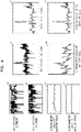
- FIG. 4 shows a battery pack current a and a battery pack voltage b measured in a battery pack including normal battery cells, and a G parameter value c and an H parameter value d estimated for the battery pack on the left, and a battery cell voltage e and a battery cell SOC(f) measured in each of normal battery cells included in the battery pack, a G parameter value g and an H parameter value h estimated for the battery cell on the right.
- Graphs a-h of FIG. 4 are using current/voltage actually-used operation pattern data of an energy storage system (ESS) of 20Ah. A structure in which four battery cells are connected in series, was used, and a time period ⁇ t was 1 second. The current flowing through the normal battery cell is the same as the current of the battery pack. Graphs a-h of FIG. 4 show changes in specific parameter values according to time (seconds).
- ESS energy storage system
- FIG. 5 shows the result of measuring or estimating one normal battery cell after it is replaced with an abnormally deteriorated cell in the battery pack of FIG. 4 .
- Graph a of FIG. 5 shows G parameter values of the normal battery cell and the abnormally deteriorated cell
- graph b of FIG. 5 shows a battery cell voltage of the normal battery cell and the abnormally deteriorated cell.
- Normal battery cells and abnormally deteriorated cells cannot be distinguished by the battery cell voltage of graph b, but normal battery cells and abnormally deteriorated cells are clearly distinguished by using the G parameter value of graph a. It can be seen that the G parameter value of the abnormally deteriorated cell is greater than the G parameter value of the normal battery cell.
- a G parameter value of a specific battery cell is compared with G parameter values of other battery cells so that it can be clearly seen that the specific battery cell is an abnormally deteriorated cell.
- the G parameter represents the sensitivity of voltage with respect to change in current of the battery cell
- the internal resistance of the battery cell may be directly reflected.
- the method of determining an abnormally deteriorated cell based on the G parameter value may have reliability.
- FIG. 6 shows the result of measuring or estimating one normal battery cell after it is replaced with an abnormally reduced capacity cell in the battery pack of FIG. 4 .
- Graph a of FIG. 6 shows battery cell voltages of the normal battery cell and the abnormally reduced capacity cell
- graph b of FIG. 6 shows a battery cell SOC of the normal battery cell and the abnormally reduced capacity cell
- graph c of FIG. 6 shows G parameter values of the normal battery cell and the abnormally reduced capacity cell
- graph d of FIG. 6 shows H parameter values of the normal battery cell and the abnormally reduced capacity cell.
Landscapes
- Physics & Mathematics (AREA)
- General Physics & Mathematics (AREA)
- Secondary Cells (AREA)
Applications Claiming Priority (2)
| Application Number | Priority Date | Filing Date | Title |
|---|---|---|---|
| KR1020190075223A KR20210000206A (ko) | 2019-06-24 | 2019-06-24 | 이상 배터리 셀 검출 방법 |
| PCT/KR2020/001667 WO2020262789A1 (ko) | 2019-06-24 | 2020-02-05 | 이상 배터리 셀 검출 방법 |
Publications (3)
| Publication Number | Publication Date |
|---|---|
| EP3988952A1 true EP3988952A1 (de) | 2022-04-27 |
| EP3988952A4 EP3988952A4 (de) | 2023-07-19 |
| EP3988952B1 EP3988952B1 (de) | 2024-05-22 |
Family
ID=74059755
Family Applications (1)
| Application Number | Title | Priority Date | Filing Date |
|---|---|---|---|
| EP20831490.6A Active EP3988952B1 (de) | 2019-06-24 | 2020-02-05 | Verfahren zur erkennung einer abnormalen batteriezelle |
Country Status (6)
| Country | Link |
|---|---|
| US (1) | US20220196754A1 (de) |
| EP (1) | EP3988952B1 (de) |
| KR (1) | KR20210000206A (de) |
| CN (1) | CN113785209B (de) |
| PL (1) | PL3988952T3 (de) |
| WO (1) | WO2020262789A1 (de) |
Families Citing this family (5)
| Publication number | Priority date | Publication date | Assignee | Title |
|---|---|---|---|---|
| KR102629463B1 (ko) | 2019-03-12 | 2024-01-25 | 삼성에스디아이 주식회사 | 배터리 건강 상태 추정 방법 |
| US11846683B2 (en) | 2019-06-24 | 2023-12-19 | Samsung Sdi Co., Ltd. | Method for detecting internal short-circuited cell |
| KR20220100471A (ko) * | 2021-01-08 | 2022-07-15 | 주식회사 엘지에너지솔루션 | 배터리 관리 장치 및 방법 |
| CN114509684B (zh) * | 2022-04-19 | 2022-07-26 | 西安因联信息科技有限公司 | 一种自适应电池电量监测方法及系统 |
| KR20240034051A (ko) * | 2022-09-06 | 2024-03-13 | 주식회사 엘지에너지솔루션 | 배터리의 이상을 감지하는 전자 장치 및 이의 동작 방법 |
Family Cites Families (16)
| Publication number | Priority date | Publication date | Assignee | Title |
|---|---|---|---|---|
| JPH0741479U (ja) * | 1993-12-27 | 1995-07-21 | アイコム株式会社 | 電池残量監視回路 |
| JP5105218B2 (ja) * | 2005-06-06 | 2012-12-26 | トヨタ自動車株式会社 | 異常判定装置 |
| KR100804698B1 (ko) * | 2006-06-26 | 2008-02-18 | 삼성에스디아이 주식회사 | 배터리 soc 추정 방법 및 이를 이용하는 배터리 관리시스템 및 구동 방법 |
| US9678164B2 (en) * | 2010-03-23 | 2017-06-13 | Furukawa Electric Co., Ltd. | Battery internal state estimating apparatus and battery internal state estimating method |
| US9417290B1 (en) * | 2012-10-06 | 2016-08-16 | Hrl Laboratories, Llc | Methods and apparatus for dynamic characterization of electrochemical systems |
| US9658291B1 (en) * | 2012-10-06 | 2017-05-23 | Hrl Laboratories, Llc | Methods and apparatus for dynamic estimation of battery open-circuit voltage |
| FR3009093B1 (fr) * | 2013-07-29 | 2017-01-13 | Renault Sa | Estimation de l'etat de vieillissement d'une batterie electrique |
| US10063066B2 (en) * | 2014-01-07 | 2018-08-28 | Utah State University | Battery control |
| US9531202B2 (en) * | 2014-03-10 | 2016-12-27 | Dell Products, L.P. | Battery management system and method for charging lithium-ion battery cells in an information handling system |
| DE102014223278A1 (de) * | 2014-11-14 | 2016-05-19 | Robert Bosch Gmbh | Vorrichtung und Verfahren zur Überwachung von Batteriezellen sowie Batteriemodul, Batterie, Batteriesystem, Fahrzeug, Computerprogramm und Computerprogrammprodukt |
| KR20160081249A (ko) * | 2014-12-31 | 2016-07-08 | 주식회사 에이치에스엘 일렉트로닉스 | 차량의 배터리 최대용량 측정 장치 및 방법 |
| JP6414558B2 (ja) * | 2016-02-01 | 2018-10-31 | 株式会社デンソー | 電池状態推定装置 |
| JP6571268B2 (ja) * | 2016-03-08 | 2019-09-04 | 株式会社東芝 | 電池監視装置及び方法 |
| US10099679B2 (en) * | 2016-10-20 | 2018-10-16 | Fca Us Llc | Battery state and parameter estimation using a mixed sigma-point kalman filtering and recursive least squares technique |
| CN107390127A (zh) * | 2017-07-11 | 2017-11-24 | 欣旺达电动汽车电池有限公司 | 一种soc估算方法 |
| US10962601B2 (en) * | 2018-09-13 | 2021-03-30 | Bae Systems Controls Inc. | Method and system for determining open connections in a battery pack |
-
2019
- 2019-06-24 KR KR1020190075223A patent/KR20210000206A/ko not_active Application Discontinuation
-
2020
- 2020-02-05 PL PL20831490.6T patent/PL3988952T3/pl unknown
- 2020-02-05 EP EP20831490.6A patent/EP3988952B1/de active Active
- 2020-02-05 CN CN202080032978.XA patent/CN113785209B/zh active Active
- 2020-02-05 WO PCT/KR2020/001667 patent/WO2020262789A1/ko unknown
- 2020-02-05 US US17/594,497 patent/US20220196754A1/en active Pending
Also Published As
| Publication number | Publication date |
|---|---|
| KR20210000206A (ko) | 2021-01-04 |
| WO2020262789A1 (ko) | 2020-12-30 |
| CN113785209A (zh) | 2021-12-10 |
| EP3988952B1 (de) | 2024-05-22 |
| CN113785209B (zh) | 2024-03-15 |
| PL3988952T3 (pl) | 2024-08-12 |
| US20220196754A1 (en) | 2022-06-23 |
| EP3988952A4 (de) | 2023-07-19 |
Similar Documents
| Publication | Publication Date | Title |
|---|---|---|
| EP3988952B1 (de) | Verfahren zur erkennung einer abnormalen batteriezelle | |
| EP3786653B1 (de) | Batteriezustandsschätzungsverfahren | |
| EP3940405B1 (de) | Verfahren zur schätzung des gesundheitszustands einer batterie | |
| JP4767558B2 (ja) | 電源装置用状態検知装置,電源装置及び電源装置に用いられる初期特性抽出装置 | |
| KR102572652B1 (ko) | 배터리의 충전상태를 추정하는 방법 | |
| KR102156404B1 (ko) | 배터리 셀 성능 테스트 장치 및 방법 | |
| EP3958006B1 (de) | Batteriediagnosevorrichtung und -verfahren | |
| US20150369875A1 (en) | Battery state estimating device | |
| EP3961233B1 (de) | Vorrichtung und verfahren zur diagnose von batteriezellen | |
| US11251472B2 (en) | System and method for operating batteries based on electrode crystal structure change | |
| JP7515956B2 (ja) | 電池診断装置および方法 | |
| EP3988954B1 (de) | Verfahren zur erkennung einer internen kurzgeschlossenen zelle | |
| US10908219B2 (en) | Battery management system with mixed electrode | |
| CN112098847B (zh) | 一种考虑机械应变的锂离子电池soc估计方法 | |
| US20230324463A1 (en) | Method and Apparatus for Operating a System for Detecting an Anomaly of an Electrical Energy Store for a Device by Means of Machine Learning Methods | |
| KR102731010B1 (ko) | 내부 단락 셀 검출 방법 | |
| EP4400853A1 (de) | Verfahren und vorrichtung zur schätzung des internen zustands einer batterie unter verwendung eines elektrochemischen modells einer batterie | |
| US20240337701A1 (en) | Device and method for detecting deteriorated battery cell | |
| EP4016099A1 (de) | Batteriediagnosevorrichtung und -verfahren | |
| CN116559675A (zh) | 电流传感器误差辨识方法、装置及电池系统 | |
| KR20240119025A (ko) | 배터리 관리 장치 및 그것의 동작 방법 | |
| KR20230164474A (ko) | 배터리의 충전 상태를 추정하는 방법 |
Legal Events
| Date | Code | Title | Description |
|---|---|---|---|
| STAA | Information on the status of an ep patent application or granted ep patent |
Free format text: STATUS: THE INTERNATIONAL PUBLICATION HAS BEEN MADE |
|
| PUAI | Public reference made under article 153(3) epc to a published international application that has entered the european phase |
Free format text: ORIGINAL CODE: 0009012 |
|
| STAA | Information on the status of an ep patent application or granted ep patent |
Free format text: STATUS: REQUEST FOR EXAMINATION WAS MADE |
|
| 17P | Request for examination filed |
Effective date: 20211013 |
|
| AK | Designated contracting states |
Kind code of ref document: A1 Designated state(s): AL AT BE BG CH CY CZ DE DK EE ES FI FR GB GR HR HU IE IS IT LI LT LU LV MC MK MT NL NO PL PT RO RS SE SI SK SM TR |
|
| DAV | Request for validation of the european patent (deleted) | ||
| DAX | Request for extension of the european patent (deleted) | ||
| A4 | Supplementary search report drawn up and despatched |
Effective date: 20230619 |
|
| RIC1 | Information provided on ipc code assigned before grant |
Ipc: G01R 31/389 20190101ALI20230613BHEP Ipc: G01R 31/396 20190101ALI20230613BHEP Ipc: G01R 31/392 20190101ALI20230613BHEP Ipc: G01R 31/36 20200101AFI20230613BHEP |
|
| GRAP | Despatch of communication of intention to grant a patent |
Free format text: ORIGINAL CODE: EPIDOSNIGR1 |
|
| STAA | Information on the status of an ep patent application or granted ep patent |
Free format text: STATUS: GRANT OF PATENT IS INTENDED |
|
| INTG | Intention to grant announced |
Effective date: 20231212 |
|
| GRAS | Grant fee paid |
Free format text: ORIGINAL CODE: EPIDOSNIGR3 |
|
| GRAA | (expected) grant |
Free format text: ORIGINAL CODE: 0009210 |
|
| STAA | Information on the status of an ep patent application or granted ep patent |
Free format text: STATUS: THE PATENT HAS BEEN GRANTED |
|
| AK | Designated contracting states |
Kind code of ref document: B1 Designated state(s): AL AT BE BG CH CY CZ DE DK EE ES FI FR GB GR HR HU IE IS IT LI LT LU LV MC MK MT NL NO PL PT RO RS SE SI SK SM TR |
|
| REG | Reference to a national code |
Ref country code: GB Ref legal event code: FG4D |
|
| REG | Reference to a national code |
Ref country code: CH Ref legal event code: EP |
|
| REG | Reference to a national code |
Ref country code: DE Ref legal event code: R096 Ref document number: 602020031399 Country of ref document: DE |
|
| REG | Reference to a national code |
Ref country code: IE Ref legal event code: FG4D |
|
| REG | Reference to a national code |
Ref country code: SE Ref legal event code: TRGR |
|
| REG | Reference to a national code |
Ref country code: LT Ref legal event code: MG9D |
|
| REG | Reference to a national code |
Ref country code: NL Ref legal event code: MP Effective date: 20240522 |
|
| PG25 | Lapsed in a contracting state [announced via postgrant information from national office to epo] |
Ref country code: IS Free format text: LAPSE BECAUSE OF FAILURE TO SUBMIT A TRANSLATION OF THE DESCRIPTION OR TO PAY THE FEE WITHIN THE PRESCRIBED TIME-LIMIT Effective date: 20240922 |
|
| PG25 | Lapsed in a contracting state [announced via postgrant information from national office to epo] |
Ref country code: BG Free format text: LAPSE BECAUSE OF FAILURE TO SUBMIT A TRANSLATION OF THE DESCRIPTION OR TO PAY THE FEE WITHIN THE PRESCRIBED TIME-LIMIT Effective date: 20240522 |
|
| PG25 | Lapsed in a contracting state [announced via postgrant information from national office to epo] |
Ref country code: FI Free format text: LAPSE BECAUSE OF FAILURE TO SUBMIT A TRANSLATION OF THE DESCRIPTION OR TO PAY THE FEE WITHIN THE PRESCRIBED TIME-LIMIT Effective date: 20240522 Ref country code: HR Free format text: LAPSE BECAUSE OF FAILURE TO SUBMIT A TRANSLATION OF THE DESCRIPTION OR TO PAY THE FEE WITHIN THE PRESCRIBED TIME-LIMIT Effective date: 20240522 |
|
| PG25 | Lapsed in a contracting state [announced via postgrant information from national office to epo] |
Ref country code: GR Free format text: LAPSE BECAUSE OF FAILURE TO SUBMIT A TRANSLATION OF THE DESCRIPTION OR TO PAY THE FEE WITHIN THE PRESCRIBED TIME-LIMIT Effective date: 20240823 |
|
| PG25 | Lapsed in a contracting state [announced via postgrant information from national office to epo] |
Ref country code: PT Free format text: LAPSE BECAUSE OF FAILURE TO SUBMIT A TRANSLATION OF THE DESCRIPTION OR TO PAY THE FEE WITHIN THE PRESCRIBED TIME-LIMIT Effective date: 20240923 |
|
| REG | Reference to a national code |
Ref country code: AT Ref legal event code: MK05 Ref document number: 1689187 Country of ref document: AT Kind code of ref document: T Effective date: 20240522 |
|
| PG25 | Lapsed in a contracting state [announced via postgrant information from national office to epo] |
Ref country code: NL Free format text: LAPSE BECAUSE OF FAILURE TO SUBMIT A TRANSLATION OF THE DESCRIPTION OR TO PAY THE FEE WITHIN THE PRESCRIBED TIME-LIMIT Effective date: 20240522 |
|
| PG25 | Lapsed in a contracting state [announced via postgrant information from national office to epo] |
Ref country code: ES Free format text: LAPSE BECAUSE OF FAILURE TO SUBMIT A TRANSLATION OF THE DESCRIPTION OR TO PAY THE FEE WITHIN THE PRESCRIBED TIME-LIMIT Effective date: 20240522 |
|
| PG25 | Lapsed in a contracting state [announced via postgrant information from national office to epo] |
Ref country code: AT Free format text: LAPSE BECAUSE OF FAILURE TO SUBMIT A TRANSLATION OF THE DESCRIPTION OR TO PAY THE FEE WITHIN THE PRESCRIBED TIME-LIMIT Effective date: 20240522 |
|
| PG25 | Lapsed in a contracting state [announced via postgrant information from national office to epo] |
Ref country code: LV Free format text: LAPSE BECAUSE OF FAILURE TO SUBMIT A TRANSLATION OF THE DESCRIPTION OR TO PAY THE FEE WITHIN THE PRESCRIBED TIME-LIMIT Effective date: 20240522 |
|
| PG25 | Lapsed in a contracting state [announced via postgrant information from national office to epo] |
Ref country code: PT Free format text: LAPSE BECAUSE OF FAILURE TO SUBMIT A TRANSLATION OF THE DESCRIPTION OR TO PAY THE FEE WITHIN THE PRESCRIBED TIME-LIMIT Effective date: 20240923 Ref country code: NO Free format text: LAPSE BECAUSE OF FAILURE TO SUBMIT A TRANSLATION OF THE DESCRIPTION OR TO PAY THE FEE WITHIN THE PRESCRIBED TIME-LIMIT Effective date: 20240822 Ref country code: NL Free format text: LAPSE BECAUSE OF FAILURE TO SUBMIT A TRANSLATION OF THE DESCRIPTION OR TO PAY THE FEE WITHIN THE PRESCRIBED TIME-LIMIT Effective date: 20240522 Ref country code: LV Free format text: LAPSE BECAUSE OF FAILURE TO SUBMIT A TRANSLATION OF THE DESCRIPTION OR TO PAY THE FEE WITHIN THE PRESCRIBED TIME-LIMIT Effective date: 20240522 Ref country code: IS Free format text: LAPSE BECAUSE OF FAILURE TO SUBMIT A TRANSLATION OF THE DESCRIPTION OR TO PAY THE FEE WITHIN THE PRESCRIBED TIME-LIMIT Effective date: 20240922 Ref country code: HR Free format text: LAPSE BECAUSE OF FAILURE TO SUBMIT A TRANSLATION OF THE DESCRIPTION OR TO PAY THE FEE WITHIN THE PRESCRIBED TIME-LIMIT Effective date: 20240522 Ref country code: GR Free format text: LAPSE BECAUSE OF FAILURE TO SUBMIT A TRANSLATION OF THE DESCRIPTION OR TO PAY THE FEE WITHIN THE PRESCRIBED TIME-LIMIT Effective date: 20240823 Ref country code: FI Free format text: LAPSE BECAUSE OF FAILURE TO SUBMIT A TRANSLATION OF THE DESCRIPTION OR TO PAY THE FEE WITHIN THE PRESCRIBED TIME-LIMIT Effective date: 20240522 Ref country code: ES Free format text: LAPSE BECAUSE OF FAILURE TO SUBMIT A TRANSLATION OF THE DESCRIPTION OR TO PAY THE FEE WITHIN THE PRESCRIBED TIME-LIMIT Effective date: 20240522 Ref country code: BG Free format text: LAPSE BECAUSE OF FAILURE TO SUBMIT A TRANSLATION OF THE DESCRIPTION OR TO PAY THE FEE WITHIN THE PRESCRIBED TIME-LIMIT Effective date: 20240522 Ref country code: AT Free format text: LAPSE BECAUSE OF FAILURE TO SUBMIT A TRANSLATION OF THE DESCRIPTION OR TO PAY THE FEE WITHIN THE PRESCRIBED TIME-LIMIT Effective date: 20240522 Ref country code: RS Free format text: LAPSE BECAUSE OF FAILURE TO SUBMIT A TRANSLATION OF THE DESCRIPTION OR TO PAY THE FEE WITHIN THE PRESCRIBED TIME-LIMIT Effective date: 20240822 |