EP3988946B1 - Measurement system and method for determining a status of a power system in a vehicle using the measurement system - Google Patents
Measurement system and method for determining a status of a power system in a vehicle using the measurement system Download PDFInfo
- Publication number
- EP3988946B1 EP3988946B1 EP20203411.2A EP20203411A EP3988946B1 EP 3988946 B1 EP3988946 B1 EP 3988946B1 EP 20203411 A EP20203411 A EP 20203411A EP 3988946 B1 EP3988946 B1 EP 3988946B1
- Authority
- EP
- European Patent Office
- Prior art keywords
- voltage
- pole
- measurement
- threshold value
- power system
- Prior art date
- Legal status (The legal status is an assumption and is not a legal conclusion. Google has not performed a legal analysis and makes no representation as to the accuracy of the status listed.)
- Active
Links
Images


Classifications
-
- G—PHYSICS
- G01—MEASURING; TESTING
- G01R—MEASURING ELECTRIC VARIABLES; MEASURING MAGNETIC VARIABLES
- G01R31/00—Arrangements for testing electric properties; Arrangements for locating electric faults; Arrangements for electrical testing characterised by what is being tested not provided for elsewhere
-
- G—PHYSICS
- G01—MEASURING; TESTING
- G01R—MEASURING ELECTRIC VARIABLES; MEASURING MAGNETIC VARIABLES
- G01R19/00—Arrangements for measuring currents or voltages or for indicating presence or sign thereof
- G01R19/0038—Circuits for comparing several input signals and for indicating the result of this comparison, e.g. equal, different, greater, smaller (comparing pulses or pulse trains according to amplitude)
-
- G—PHYSICS
- G01—MEASURING; TESTING
- G01R—MEASURING ELECTRIC VARIABLES; MEASURING MAGNETIC VARIABLES
- G01R31/00—Arrangements for testing electric properties; Arrangements for locating electric faults; Arrangements for electrical testing characterised by what is being tested not provided for elsewhere
- G01R31/36—Arrangements for testing, measuring or monitoring the electrical condition of accumulators or electric batteries, e.g. capacity or state of charge [SoC]
- G01R31/392—Determining battery ageing or deterioration, e.g. state of health
-
- B—PERFORMING OPERATIONS; TRANSPORTING
- B60—VEHICLES IN GENERAL
- B60L—PROPULSION OF ELECTRICALLY-PROPELLED VEHICLES; SUPPLYING ELECTRIC POWER FOR AUXILIARY EQUIPMENT OF ELECTRICALLY-PROPELLED VEHICLES; ELECTRODYNAMIC BRAKE SYSTEMS FOR VEHICLES IN GENERAL; MAGNETIC SUSPENSION OR LEVITATION FOR VEHICLES; MONITORING OPERATING VARIABLES OF ELECTRICALLY-PROPELLED VEHICLES; ELECTRIC SAFETY DEVICES FOR ELECTRICALLY-PROPELLED VEHICLES
- B60L58/00—Methods or circuit arrangements for monitoring or controlling batteries or fuel cells, specially adapted for electric vehicles
- B60L58/10—Methods or circuit arrangements for monitoring or controlling batteries or fuel cells, specially adapted for electric vehicles for monitoring or controlling batteries
- B60L58/16—Methods or circuit arrangements for monitoring or controlling batteries or fuel cells, specially adapted for electric vehicles for monitoring or controlling batteries responding to battery ageing, e.g. to the number of charging cycles or the state of health [SoH]
-
- G—PHYSICS
- G01—MEASURING; TESTING
- G01R—MEASURING ELECTRIC VARIABLES; MEASURING MAGNETIC VARIABLES
- G01R19/00—Arrangements for measuring currents or voltages or for indicating presence or sign thereof
- G01R19/165—Indicating that current or voltage is either above or below a predetermined value or within or outside a predetermined range of values
- G01R19/16566—Circuits and arrangements for comparing voltage or current with one or several thresholds and for indicating the result not covered by subgroups G01R19/16504, G01R19/16528, G01R19/16533
- G01R19/16576—Circuits and arrangements for comparing voltage or current with one or several thresholds and for indicating the result not covered by subgroups G01R19/16504, G01R19/16528, G01R19/16533 comparing DC or AC voltage with one threshold
-
- G—PHYSICS
- G01—MEASURING; TESTING
- G01R—MEASURING ELECTRIC VARIABLES; MEASURING MAGNETIC VARIABLES
- G01R19/00—Arrangements for measuring currents or voltages or for indicating presence or sign thereof
- G01R19/25—Arrangements for measuring currents or voltages or for indicating presence or sign thereof using digital measurement techniques
- G01R19/2513—Arrangements for monitoring electric power systems, e.g. power lines or loads; Logging
-
- G—PHYSICS
- G01—MEASURING; TESTING
- G01R—MEASURING ELECTRIC VARIABLES; MEASURING MAGNETIC VARIABLES
- G01R31/00—Arrangements for testing electric properties; Arrangements for locating electric faults; Arrangements for electrical testing characterised by what is being tested not provided for elsewhere
- G01R31/36—Arrangements for testing, measuring or monitoring the electrical condition of accumulators or electric batteries, e.g. capacity or state of charge [SoC]
- G01R31/367—Software therefor, e.g. for battery testing using modelling or look-up tables
-
- H—ELECTRICITY
- H01—ELECTRIC ELEMENTS
- H01M—PROCESSES OR MEANS, e.g. BATTERIES, FOR THE DIRECT CONVERSION OF CHEMICAL ENERGY INTO ELECTRICAL ENERGY
- H01M10/00—Secondary cells; Manufacture thereof
- H01M10/42—Methods or arrangements for servicing or maintenance of secondary cells or secondary half-cells
- H01M10/48—Accumulators combined with arrangements for measuring, testing or indicating the condition of cells, e.g. the level or density of the electrolyte
-
- G—PHYSICS
- G01—MEASURING; TESTING
- G01R—MEASURING ELECTRIC VARIABLES; MEASURING MAGNETIC VARIABLES
- G01R35/00—Testing or calibrating of apparatus covered by the other groups of this subclass
-
- Y—GENERAL TAGGING OF NEW TECHNOLOGICAL DEVELOPMENTS; GENERAL TAGGING OF CROSS-SECTIONAL TECHNOLOGIES SPANNING OVER SEVERAL SECTIONS OF THE IPC; TECHNICAL SUBJECTS COVERED BY FORMER USPC CROSS-REFERENCE ART COLLECTIONS [XRACs] AND DIGESTS
- Y02—TECHNOLOGIES OR APPLICATIONS FOR MITIGATION OR ADAPTATION AGAINST CLIMATE CHANGE
- Y02E—REDUCTION OF GREENHOUSE GAS [GHG] EMISSIONS, RELATED TO ENERGY GENERATION, TRANSMISSION OR DISTRIBUTION
- Y02E60/00—Enabling technologies; Technologies with a potential or indirect contribution to GHG emissions mitigation
- Y02E60/10—Energy storage using batteries
-
- Y—GENERAL TAGGING OF NEW TECHNOLOGICAL DEVELOPMENTS; GENERAL TAGGING OF CROSS-SECTIONAL TECHNOLOGIES SPANNING OVER SEVERAL SECTIONS OF THE IPC; TECHNICAL SUBJECTS COVERED BY FORMER USPC CROSS-REFERENCE ART COLLECTIONS [XRACs] AND DIGESTS
- Y02—TECHNOLOGIES OR APPLICATIONS FOR MITIGATION OR ADAPTATION AGAINST CLIMATE CHANGE
- Y02T—CLIMATE CHANGE MITIGATION TECHNOLOGIES RELATED TO TRANSPORTATION
- Y02T10/00—Road transport of goods or passengers
- Y02T10/60—Other road transportation technologies with climate change mitigation effect
- Y02T10/70—Energy storage systems for electromobility, e.g. batteries
Definitions
- the invention relates to a measurement system and method for determining a status of a power system in an electrical or hybrid vehicle.
- the invention relates to a system and method for ensuring the absence of hazardous voltages in a high-voltage system of an electrical vehicle.
- the invention is applicable in electrical and hybrid vehicles within the fields of trucks, buses, industrial construction machines and the like. Although the invention will be described with reference to a truck, the invention is not restricted to this particular vehicle, but may also be used in other electric vehicles.
- a secure measurement is performed to confirm the absence of hazardous voltages in the system.
- Such a secure measurement is often performed by connecting an external device to the vehicle power system and measuring the voltage at a selected location.
- US 2018/024201 A1 describes A battery monitoring system including a multiplexer, a self-diagnosis voltage generation circuit, a first voltage measuring circuit and a voltage measuring circuit which measure voltage signals in a first route and a second route inputted through the multiplexer, based on the self-diagnosis voltage generated from the self-diagnosis voltage generation circuit or based on the voltages of battery cells outputted from the input circuit.
- JP 2013 024800 A relates to a voltage detection apparatus which detects the cell voltage of each battery cell of the assembled battery with which the battery cell was connected in series.
- US 2018/024198 A1 discloses a battery monitoring system including an input circuit to which voltage signals of battery cells are inputted; a multiplexer selecting a battery cell for voltage detection from the battery cells, selecting voltage signals inputted from the input circuit, and outputting the selected voltage signals; first and a second voltage measuring circuits simultaneously measuring voltages based on the voltage signals in first and second routes outputted from the multiplexer.
- An object of the invention is to provide a measurement system for determining a status of a power system in a vehicle to improve the safety in a high-voltage power system by ensuring that there are no hazardous voltages in the system.
- a measurement system for determining a status of a power system in a vehicle.
- the system measurement comprising: a first voltage measurement unit and a second voltage measurement unit, each of the first and second voltage measurement units being connectable between a positive pole and a negative pole of the power system; a measurement system control unit connected to the first and second voltage measurement unit and configured to: control the first and second voltage measurement unit to simultaneously measure a voltage to determine a respective first and second pole-to-pole voltage; compare the first pole-to-pole voltage with the second pole-to-pole voltage to determine a voltage difference, and if the voltage difference is higher than a voltage threshold value, provide an indication that the voltage measurement is not reliable.
- the power system herein refers to a system for providing electrical power to electrical components of a vehicle.
- the energy source may be a battery arranged to provide power to an electrical motor for vehicle propulsion, or in the case of a working machine, to an implement of the working machine.
- the high-voltage system typically operates at voltages over 200V, and often the in the range of 400V to 1000V in order to provide propulsive power for heavy vehicles such as trucks and buses.
- the present invention is based on the realization that improved safety in a high-voltage power system for a vehicle can be achieved by independently measuring the pole-to-pole voltage at two separate locations in the system, thereby increasing the reliability and eliminating a number of possible hazards compared to prior art solutions where an external device is connected to the power system.
- both voltage measurement units are arranged to simultaneously measure a respective pole-to-pole voltage, the measurement results should be the same, at least within the tolerances of the measurement unit, for each measurement.
- the first and second voltage measurement units may be connected at different locations in the power system where the same pole-to-pole voltages are expected. By comparing the two measured voltages, it can be detected both if an absolute value of a measured voltage exceeds safety limits but also if the two voltages differ, which may be caused by a malfunctioning voltage measurement unit or by an electrical fault in the high-voltage system.
- a further advantage of the claimed measurement system is that the two measurements are entirely independent of each other and where the evaluation system is the only shared feature. This means that the overall system reliability can be determined as a multiplication of the two failure probabilities of the respective voltage measurement units, which in turn means that the total failure probability is very low.
- the user can be alerted that there may be a hazardous voltage in the vehicle and appropriate precautions can be taken.
- control unit is further configured to control the first and second voltage measurement units to repeatedly measure the respective first and second voltage.
- the measurements may for example be performed repeatedly as long as work is being performed, thereby ensuring that a mechanic is safe when working with the vehicle.
- the voltage measurement units may for example be configured to repeatedly measure the first and second voltage with a fixed interval, wherein the fixed interval is in the range of 10ms to 500ms.
- control unit is further configured to provide an indication that the voltage measurement is unreliable only if a predetermined number of consecutive voltage differences between the first and second pole-to-pole voltages are above the voltage threshold value.
- the number of consecutive measurements that are required can be determined based on operational parameters of the system, and also based on the thresholds used. For example, for a lower voltage threshold value the required number of consecutive measurements can be set higher compared to if a higher voltage threshold value is used.
- control unit is further configured to detect a change between an active status and a passive status of the power system, and to suppress providing an indication if the voltage difference exceeds the voltage threshold value during the change between active status and passive status.
- the control unit is further configured to detect a change between an active status and a passive status of the power system, and to suppress providing an indication if the voltage difference exceeds the voltage threshold value during the change between active status and passive status.
- the system is changed between an active status and a passive status, i.e. when the system is started or shut down, there may be voltage transients and/or other voltage swings which are not indicative of a fault in the system. Accordingly, it may be desirable to not provide an indication that the voltage measurement is unreliable during such a change-period, even if the difference in voltage exceeds a previously set threshold value.
- control unit may be further configured to use a first voltage threshold value if the power system is in a stable state and a second voltage threshold value if the system is in a transitional state, wherein the second voltage threshold value is higher than the first voltage threshold value.
- the system may further comprise a display arranged to be visible to an operator, wherein the display is configured to show the first and second pole-to-pole voltages.
- the operator can thus monitor the voltages in person to ensure both that the measurements are reliable, and that system is safe.
- the display may be mounted on the vehicle. It is also possible to provide a remote monitoring device where the vehicle sends the measurement results to an external device.
- the external device may be a dedicated display device, or it may be provided in the form of functionality integrated in a smartphone, a tablet or the like in the form of an app.
- the system may further comprise a notification unit configured to provide a visual and/or audible indication if the voltage is not reliable.
- the notification unit may be a separate unit configured to sound an alarm or to flash a light if a measurement is shown to be unreliable.
- a notification may also be provided by a horn, a buzzer, or lights of the vehicle.
- a power system for a vehicle comprising: a high-voltage energy source; a high-voltage system; and a measurement system according to any one of the preceding embodiments, and a vehicle comprising such a power system.
- a method for determining a status of a power system in a vehicle comprising: a first voltage measurement unit and a second voltage measurement unit, each of the first and second voltage measurement units being connected between a positive pole and a negative pole of the power system; and a measurement system control unit connected to the first and second voltage measurement unit.
- the method comprises: controlling the first and second voltage measurement unit to simultaneously measure a voltage to determine a respective first and second pole-to-pole voltage; comparing the first and second pole-to-pole voltages; and if a voltage difference is higher than a voltage threshold value, providing an indication that the voltage measurement is not reliable.
- a safety circuit for a power system is mainly discussed with reference to a power system in a truck. It should however be noted that this by no means limits the scope of the present invention since the described invention is equally applicable in other types of vehicles such as cars, buses and construction vehicles.
- the described safety circuit may also be used in marine applications such as boats and ships, and in other applications comprising a high-voltage power source and a high-voltage system.
- Fig. 1 is a circuit schematic illustrating measurement system 100 for determining a status of a high-voltage power system in a vehicle.
- the measurement system comprises a first voltage measurement unit 102 and a second voltage measurement unit 104, each of the first and second voltage measurement units being connected between a positive pole 106 and a negative pole 108 of the power system.
- the system further comprises a measurement system control unit 110 connected to the first and second voltage measurement units 102, 104.
- the measurement system control unit 110 is configured to control the first and second voltage measurement units 102, 104 to simultaneously measure a voltage to determine a respective first and second pole-to-pole voltage, U p-p1 , U p-p2 , and to compare the first pole-to-pole voltage U p-p1 with the second pole-to-pole voltage U p-p2 .
- the measurement system control unit 110 may include a microprocessor, microcontroller, programmable digital signal processor or another programmable device.
- the control unit may also, or instead, include an application specific integrated circuit, a programmable gate array or programmable array logic, a programmable logic device, or a digital signal processor.
- the control unit includes a programmable device such as the microprocessor, microcontroller or programmable digital signal processor mentioned above, the processor may further include computer executable code that controls operation of the programmable device.
- the functionality of the measurement system control unit 110 may also be integrated in one or more general purpose or dedicated ECUs (electronic control units) of the vehicle.
- Fig. 2 further illustrates a display device 112 where the results of the two voltage measurements U p-p1 and U p-p2 are displayed.
- the voltage threshold value may be in the range of 30V to 50V, such as 40V.
- the threshold value and sampling rate of the voltage measurement units may be determined based on a reliability of the specific units and on the system properties as a while. A typical value would be to measure or sample the voltage every 10ms and consider that a fault is detected if three consecutive samples indicate a fail, i.e. a voltage difference value higher than the voltage threshold value.
- the two voltage measurement units 102, 104 may be arranged in different housings, and the two may also be of different type and/or come from different manufacturers.
- Fig. 2 schematically illustrates an example power system 200 comprising the measurement system 100 described above with reference to Fig. 1 .
- the power system 200 comprises a high-voltage energy source 202 a high-voltage system 204.
- the high-voltage energy source 202 comprises a plurality of battery packs connected to the high-voltage system 204 via a junction box 206.
- the high-voltage system 204 is here illustrated as two electrical machines 208a-b for providing vehicle propulsion, each electrical machine being controlled by a corresponding electric motor drive unit 210a-b.
- the voltage measurement units may for example be integrated in the electric motor drive unit 210a-b, and since the two voltage measurement units are then only separated by a junction box, they are expected to give the same result.
- a voltage measurement unit may also be integrated in a DC-DC converter 212 of the high voltage system.
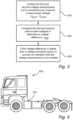
- Fig. 3 is a flow chart outlining the general steps of a method which may be performed by the above described measurement system control unit 110.
- the method comprises controlling 300 the first and second voltage measurement unit to simultaneously measure a voltage to determine a respective first and second pole-to-pole voltage, Up-p1, Up-p2.
- the first and second pole-to-pole voltage, U p-p1 , U p-p2 are compared 302 to determine a voltage difference, U diff .
- the method comprises providing 304 an indication that the voltage measurement is not reliable.
- Fig. 4 is a vehicle 400 comprising a measurement system 100 for determining a status of a high-voltage power system according to any of the aforementioned embodiments and examples.
Landscapes
- Engineering & Computer Science (AREA)
- Physics & Mathematics (AREA)
- General Physics & Mathematics (AREA)
- Power Engineering (AREA)
- Electrochemistry (AREA)
- Chemical Kinetics & Catalysis (AREA)
- Chemical & Material Sciences (AREA)
- General Chemical & Material Sciences (AREA)
- Life Sciences & Earth Sciences (AREA)
- Sustainable Development (AREA)
- Sustainable Energy (AREA)
- Manufacturing & Machinery (AREA)
- Transportation (AREA)
- Mechanical Engineering (AREA)
- Electric Propulsion And Braking For Vehicles (AREA)
Description
- The invention relates to a measurement system and method for determining a status of a power system in an electrical or hybrid vehicle. In particular, the invention relates to a system and method for ensuring the absence of hazardous voltages in a high-voltage system of an electrical vehicle.
- The invention is applicable in electrical and hybrid vehicles within the fields of trucks, buses, industrial construction machines and the like. Although the invention will be described with reference to a truck, the invention is not restricted to this particular vehicle, but may also be used in other electric vehicles.
- In vehicles comprising electrical or hybrid drive systems, it is important to be able to safely disconnect the high-voltage energy source from the other high-voltage vehicle systems, for example for allowing the vehicle to be serviced and repaired in a secure manner. There are typically ways of manually shutting down or otherwise disconnecting the high-voltage system. However, due to the potentially great hazards of working with a high-voltage system that has not been properly shut down, back-up systems for ensuring that no high-voltage components are accessible to a user are desirable.
- Moreover, according to safety standards such as CENELEC - EN 50110, it is required that a secure measurement is performed to confirm the absence of hazardous voltages in the system. Such a secure measurement is often performed by connecting an external device to the vehicle power system and measuring the voltage at a selected location.
-
US 2018/024201 A1 describes A battery monitoring system including a multiplexer, a self-diagnosis voltage generation circuit, a first voltage measuring circuit and a voltage measuring circuit which measure voltage signals in a first route and a second route inputted through the multiplexer, based on the self-diagnosis voltage generated from the self-diagnosis voltage generation circuit or based on the voltages of battery cells outputted from the input circuit. -
JP 2013 024800 A -
US 2018/024198 A1 discloses a battery monitoring system including an input circuit to which voltage signals of battery cells are inputted; a multiplexer selecting a battery cell for voltage detection from the battery cells, selecting voltage signals inputted from the input circuit, and outputting the selected voltage signals; first and a second voltage measuring circuits simultaneously measuring voltages based on the voltage signals in first and second routes outputted from the multiplexer. - However, when connecting an external device there is always a risk of a faulty connection or that the external device may malfunction and/or show a faulty result. Accordingly, it is desirable to further improve the safety of a high-power vehicle system.
- An object of the invention is to provide a measurement system for determining a status of a power system in a vehicle to improve the safety in a high-voltage power system by ensuring that there are no hazardous voltages in the system.
- According to a first aspect of the invention as defined in claim 1, there is provided a measurement system for determining a status of a power system in a vehicle. The system measurement comprising: a first voltage measurement unit and a second voltage measurement unit, each of the first and second voltage measurement units being connectable between a positive pole and a negative pole of the power system; a measurement system control unit connected to the first and second voltage measurement unit and configured to: control the first and second voltage measurement unit to simultaneously measure a voltage to determine a respective first and second pole-to-pole voltage; compare the first pole-to-pole voltage with the second pole-to-pole voltage to determine a voltage difference, and if the voltage difference is higher than a voltage threshold value, provide an indication that the voltage measurement is not reliable.
- The power system herein refers to a system for providing electrical power to electrical components of a vehicle. The energy source may be a battery arranged to provide power to an electrical motor for vehicle propulsion, or in the case of a working machine, to an implement of the working machine. The high-voltage system typically operates at voltages over 200V, and often the in the range of 400V to 1000V in order to provide propulsive power for heavy vehicles such as trucks and buses.
- The present invention is based on the realization that improved safety in a high-voltage power system for a vehicle can be achieved by independently measuring the pole-to-pole voltage at two separate locations in the system, thereby increasing the reliability and eliminating a number of possible hazards compared to prior art solutions where an external device is connected to the power system.
- Since both voltage measurement units are arranged to simultaneously measure a respective pole-to-pole voltage, the measurement results should be the same, at least within the tolerances of the measurement unit, for each measurement. Moreover, the first and second voltage measurement units may be connected at different locations in the power system where the same pole-to-pole voltages are expected. By comparing the two measured voltages, it can be detected both if an absolute value of a measured voltage exceeds safety limits but also if the two voltages differ, which may be caused by a malfunctioning voltage measurement unit or by an electrical fault in the high-voltage system.
- A further advantage of the claimed measurement system is that the two measurements are entirely independent of each other and where the evaluation system is the only shared feature. This means that the overall system reliability can be determined as a multiplication of the two failure probabilities of the respective voltage measurement units, which in turn means that the total failure probability is very low.
- Moreover, by providing a notification to a user that the voltage measurement is not reliable, the user can be alerted that there may be a hazardous voltage in the vehicle and appropriate precautions can be taken.
- According to the invention, the control unit is further configured to control the first and second voltage measurement units to repeatedly measure the respective first and second voltage. The measurements may for example be performed repeatedly as long as work is being performed, thereby ensuring that a mechanic is safe when working with the vehicle. The voltage measurement units may for example be configured to repeatedly measure the first and second voltage with a fixed interval, wherein the fixed interval is in the range of 10ms to 500ms.
- According to one embodiment of the invention, the control unit is further configured to provide an indication that the voltage measurement is unreliable only if a predetermined number of consecutive voltage differences between the first and second pole-to-pole voltages are above the voltage threshold value. This has the advantage that an alarm or the like is not triggered based on transients or other brief spurious events. The number of consecutive measurements that are required can be determined based on operational parameters of the system, and also based on the thresholds used. For example, for a lower voltage threshold value the required number of consecutive measurements can be set higher compared to if a higher voltage threshold value is used.
- According to the invention, the control unit is further configured to detect a change between an active status and a passive status of the power system, and to suppress providing an indication if the voltage difference exceeds the voltage threshold value during the change between active status and passive status. When the system is changed between an active status and a passive status, i.e. when the system is started or shut down, there may be voltage transients and/or other voltage swings which are not indicative of a fault in the system. Accordingly, it may be desirable to not provide an indication that the voltage measurement is unreliable during such a change-period, even if the difference in voltage exceeds a previously set threshold value.
- According to one embodiment of the invention the control unit may be further configured to use a first voltage threshold value if the power system is in a stable state and a second voltage threshold value if the system is in a transitional state, wherein the second voltage threshold value is higher than the first voltage threshold value. Thereby, the comparison of the two voltage measurements is performed also during a transition period between active and passive status, but with a different threshold value taking the possible voltage variations during start-up and shut down into account.
- According to one embodiment of the invention, the system may further comprise a display arranged to be visible to an operator, wherein the display is configured to show the first and second pole-to-pole voltages. The operator can thus monitor the voltages in person to ensure both that the measurements are reliable, and that system is safe. The display may be mounted on the vehicle. It is also possible to provide a remote monitoring device where the vehicle sends the measurement results to an external device. The external device may be a dedicated display device, or it may be provided in the form of functionality integrated in a smartphone, a tablet or the like in the form of an app.
- According to one embodiment of the invention, the system may further comprise a notification unit configured to provide a visual and/or audible indication if the voltage is not reliable. The notification unit may be a separate unit configured to sound an alarm or to flash a light if a measurement is shown to be unreliable. A notification may also be provided by a horn, a buzzer, or lights of the vehicle.
- There is also provided a power system for a vehicle comprising: a high-voltage energy source; a high-voltage system; and a measurement system according to any one of the preceding embodiments, and a vehicle comprising such a power system.
- According to a second aspect of the invention as defined in claim 9, there is provided a method for determining a status of a power system in a vehicle, the power system comprising: a first voltage measurement unit and a second voltage measurement unit, each of the first and second voltage measurement units being connected between a positive pole and a negative pole of the power system; and a measurement system control unit connected to the first and second voltage measurement unit. The method comprises: controlling the first and second voltage measurement unit to simultaneously measure a voltage to determine a respective first and second pole-to-pole voltage; comparing the first and second pole-to-pole voltages; and if a voltage difference is higher than a voltage threshold value, providing an indication that the voltage measurement is not reliable.
- Effects and features of this second aspect of the present invention are largely analogous to those described above in connection with the first aspect of the invention.
- Further advantages and advantageous features of the invention are disclosed in the following description and in the dependent claims.
- With reference to the appended drawings, below follows a more detailed description of embodiments of the invention cited as examples.
- In the drawings:
-
Fig. 1 is a schematic illustration of safety circuit in a power system according to an embodiment of the invention; -
Fig. 2 is a schematic illustration of safety circuit in a power system according to an embodiment of the invention; -
Fig. 3 is a flow chart outlining a method of controlling a safety circuit in a power system according to an embodiment of the invention, and -
Fig. 4 is a vehicle comprising a power system according to an embodiment of the invention. - In the present detailed description, various embodiments of a safety circuit for a power system according to the present invention are mainly discussed with reference to a power system in a truck. It should however be noted that this by no means limits the scope of the present invention since the described invention is equally applicable in other types of vehicles such as cars, buses and construction vehicles. The described safety circuit may also be used in marine applications such as boats and ships, and in other applications comprising a high-voltage power source and a high-voltage system.
-
Fig. 1 is a circuit schematicillustrating measurement system 100 for determining a status of a high-voltage power system in a vehicle. The measurement system comprises a firstvoltage measurement unit 102 and a secondvoltage measurement unit 104, each of the first and second voltage measurement units being connected between apositive pole 106 and anegative pole 108 of the power system. The system further comprises a measurementsystem control unit 110 connected to the first and secondvoltage measurement units - The measurement
system control unit 110 is configured to control the first and secondvoltage measurement units - The measurement
system control unit 110 may include a microprocessor, microcontroller, programmable digital signal processor or another programmable device. The control unit may also, or instead, include an application specific integrated circuit, a programmable gate array or programmable array logic, a programmable logic device, or a digital signal processor. Where the control unit includes a programmable device such as the microprocessor, microcontroller or programmable digital signal processor mentioned above, the processor may further include computer executable code that controls operation of the programmable device. The functionality of the measurementsystem control unit 110 may also be integrated in one or more general purpose or dedicated ECUs (electronic control units) of the vehicle. -
Fig. 2 further illustrates adisplay device 112 where the results of the two voltage measurements Up-p1 and Up-p2 are displayed. As illustrated inFig. 1 , there are no other components located between the two voltage measurement units. Accordingly, there should be no difference between the two measured voltages assuming that the measurements are performed at the same time. In an example embodiment, the voltage threshold value may be in the range of 30V to 50V, such as 40V. In practice, the threshold value and sampling rate of the voltage measurement units may be determined based on a reliability of the specific units and on the system properties as a while. A typical value would be to measure or sample the voltage every 10ms and consider that a fault is detected if three consecutive samples indicate a fail, i.e. a voltage difference value higher than the voltage threshold value. - To further ensure the independence of the voltage measurements, the two
voltage measurement units -
Fig. 2 schematically illustrates anexample power system 200 comprising themeasurement system 100 described above with reference toFig. 1 . Thepower system 200 comprises a high-voltage energy source 202 a high-voltage system 204. In the illustrated example, the high-voltage energy source 202 comprises a plurality of battery packs connected to the high-voltage system 204 via ajunction box 206. The high-voltage system 204 is here illustrated as twoelectrical machines 208a-b for providing vehicle propulsion, each electrical machine being controlled by a corresponding electricmotor drive unit 210a-b. The voltage measurement units may for example be integrated in the electricmotor drive unit 210a-b, and since the two voltage measurement units are then only separated by a junction box, they are expected to give the same result. A voltage measurement unit may also be integrated in a DC-DC converter 212 of the high voltage system. -
Fig. 3 is a flow chart outlining the general steps of a method which may be performed by the above described measurementsystem control unit 110. The method comprises controlling 300 the first and second voltage measurement unit to simultaneously measure a voltage to determine a respective first and second pole-to-pole voltage, Up-p1, Up-p2. - Next, the first and second pole-to-pole voltage, Up-p1, Up-p2 are compared 302 to determine a voltage difference, Udiff. Finally, if the voltage difference Udiff is higher than a voltage threshold value UT, the method comprises providing 304 an indication that the voltage measurement is not reliable.
-
Fig. 4 is avehicle 400 comprising ameasurement system 100 for determining a status of a high-voltage power system according to any of the aforementioned embodiments and examples. - It is to be understood that the present invention is not limited to the embodiments described above and illustrated in the drawings; rather, the skilled person will recognize that many changes and modifications may be made within the scope of the appended claims.
Claims (12)
- A measurement system (100) for determining a status of a high-voltage power system (200) in a vehicle (400), the measurement system comprising:a first voltage measurement unit (102) and a second voltage measurement unit (104), each of the first and second voltage measurement units being connectable between a positive pole (106) and a negative pole (108) of the power system;a measurement system control unit (110) connected to the first and second voltage measurement unit and configured to:control the first and second voltage measurement unit to repeatedly and simultaneously measure a voltage to determine a respective first and second pole-to-pole voltage;compare the first pole-to-pole voltage with the second pole-to-pole voltage to determine a voltage difference, and if the voltage difference is higher than a voltage threshold value, provide an indication that the voltage measurement is not reliable; anddetect a change between an active status and a passive status of the power system, characterised in that the measurement system control unit is configured to suppress providing an indication if the voltage difference exceeds the voltage threshold value during the change between active status and passive status.
- The measurement system according to claim 1, wherein the control unit is further configured to control the first and second voltage measurement units to repeatedly measure the respective first and second voltages with a fixed interval, wherein the fixed interval is in the range of 10ms to 500ms.
- The measurement system according to claim 1 or 2, wherein the control unit is further configured to provide an indication that the voltage measurement is unreliable only if a predetermined number of consecutive voltage differences between the first and second pole-to-pole voltages are above the voltage threshold value.
- The measurement system according to any one of the preceding claims, wherein the control unit is further configured to use, as the voltage threshold value, a first voltage threshold value if the power system is in a stable state and a second voltage threshold value if the power system is in a transitional state, wherein the second voltage threshold value is higher than the first voltage threshold value.
- The measurement system according to any one of the preceding claims further comprising a display arranged to be visible to an operator, wherein the display is configured to show the first and second pole-to-pole voltage.
- The measurement system according to any one of the preceding claims further comprising a notification unit (112) configured to provide a visual and/or audible indication if the voltage is not reliable.
- A power system (200) for a vehicle comprising:a high-voltage energy source (202);a high-voltage system (204); anda measurement system (100) according to any one of the preceding claims.
- A vehicle (400) comprising a power system according to claim 7.
- Method for determining a status of a high-voltage power system (200) in a vehicle (400), the power system comprising: a first voltage measurement unit (102) and a second voltage measurement unit (104), each of the first and second voltage measurement units being connected between a positive pole (106) and a negative pole (108) of the power system; and a measurement system control unit (110) connected to the first and second voltage measurement unit; wherein the method comprises:controlling (300) the first and second voltage measurement unit to repeatedly and simultaneously measure a voltage to determine a respective first and second pole-to-pole voltage;comparing (302) the first and second pole-to-pole voltages to determine a voltage difference;if the voltage difference is higher than a voltage threshold value, providing (304) an indication that the voltage measurement is not reliable; detecting a change between an active status and a passive status of the power system; characterised bysuppressing providing an indication if the voltage difference exceeds the voltage threshold value during the change between active status and passive status.
- The method according to claim 9, further comprising measuring the respective first and second voltages repeatedly and with a fixed interval.
- The method according to claim 9 or 10, further comprising providing an indication that the voltage measurement is unreliable only if a predetermined number of consecutive voltage differences between the first and second pole-to-pole voltages are above the voltage threshold value.
- The method according to any one of claims 9 to 11, further comprising:if the power system is in a stable state, comparing the voltage difference with a first voltage threshold value as the voltage threshold value; andif the power system is in a transitional state, comparing the voltage difference with a second voltage threshold value as the voltage threshold value, wherein the second voltage threshold value is higher than the first voltage threshold value.
Priority Applications (3)
| Application Number | Priority Date | Filing Date | Title |
|---|---|---|---|
| EP20203411.2A EP3988946B1 (en) | 2020-10-22 | 2020-10-22 | Measurement system and method for determining a status of a power system in a vehicle using the measurement system |
| CN202111201877.3A CN114384346A (en) | 2020-10-22 | 2021-10-15 | Measurement system and method for determining state of power system in vehicle using the same |
| US17/451,240 US12055594B2 (en) | 2020-10-22 | 2021-10-18 | Measurement system and method for determining a status of a power system in a vehicle using the measurement system |
Applications Claiming Priority (1)
| Application Number | Priority Date | Filing Date | Title |
|---|---|---|---|
| EP20203411.2A EP3988946B1 (en) | 2020-10-22 | 2020-10-22 | Measurement system and method for determining a status of a power system in a vehicle using the measurement system |
Publications (3)
| Publication Number | Publication Date |
|---|---|
| EP3988946A1 EP3988946A1 (en) | 2022-04-27 |
| EP3988946C0 EP3988946C0 (en) | 2024-12-18 |
| EP3988946B1 true EP3988946B1 (en) | 2024-12-18 |
Family
ID=73043016
Family Applications (1)
| Application Number | Title | Priority Date | Filing Date |
|---|---|---|---|
| EP20203411.2A Active EP3988946B1 (en) | 2020-10-22 | 2020-10-22 | Measurement system and method for determining a status of a power system in a vehicle using the measurement system |
Country Status (3)
| Country | Link |
|---|---|
| US (1) | US12055594B2 (en) |
| EP (1) | EP3988946B1 (en) |
| CN (1) | CN114384346A (en) |
Families Citing this family (1)
| Publication number | Priority date | Publication date | Assignee | Title |
|---|---|---|---|---|
| US20230087283A1 (en) * | 2021-09-20 | 2023-03-23 | Atieva, Inc. | Dynamic sensor data collection |
Family Cites Families (13)
| Publication number | Priority date | Publication date | Assignee | Title |
|---|---|---|---|---|
| DE102008006223A1 (en) | 2008-01-25 | 2009-08-06 | Volkswagen Ag | Voltage detecting device for use in high volt system of e.g. hybrid vehicle, has matrix-shaped electrical display unit provided for two-dimensional representation of voltages and reference voltage |
| DE102010056235A1 (en) * | 2010-12-24 | 2012-06-28 | Audi Ag | Method for testing a test device |
| JP5712841B2 (en) * | 2011-07-25 | 2015-05-07 | 株式会社デンソー | Voltage detector |
| JP5915749B2 (en) * | 2012-07-27 | 2016-05-11 | 日産自動車株式会社 | Vehicle control apparatus and vehicle control method |
| DE102012015059A1 (en) | 2012-07-28 | 2014-05-15 | Volkswagen Aktiengesellschaft | Method for deactivating a high voltage system of a motor vehicle |
| DE102013217748B4 (en) * | 2013-09-05 | 2015-04-02 | Continental Automotive Gmbh | Multifunctional monitoring of electrical systems in a motor vehicle |
| JP6597273B2 (en) * | 2015-12-17 | 2019-10-30 | 株式会社デンソー | Motor control device |
| JP6496687B2 (en) * | 2016-07-21 | 2019-04-03 | 矢崎総業株式会社 | Battery monitoring system |
| JP6539618B2 (en) * | 2016-07-21 | 2019-07-03 | 矢崎総業株式会社 | Battery monitoring system |
| KR102247391B1 (en) * | 2016-07-25 | 2021-05-03 | 삼성에스디아이 주식회사 | Battery system |
| CN106904077B (en) * | 2017-03-23 | 2019-04-09 | 深圳腾势新能源汽车有限公司 | A kind of electric car motor control method and system |
| US11189891B2 (en) * | 2017-07-03 | 2021-11-30 | Gs Yuasa Interational Ltd. | Energy storage apparatus, vehicle, and motorcycle |
| CN110789347B (en) * | 2019-10-29 | 2021-07-16 | 合肥阳光电动力科技有限公司 | Load on-off control system and control method thereof, and electric automobile |
-
2020
- 2020-10-22 EP EP20203411.2A patent/EP3988946B1/en active Active
-
2021
- 2021-10-15 CN CN202111201877.3A patent/CN114384346A/en active Pending
- 2021-10-18 US US17/451,240 patent/US12055594B2/en active Active
Also Published As
| Publication number | Publication date |
|---|---|
| US20220128630A1 (en) | 2022-04-28 |
| CN114384346A (en) | 2022-04-22 |
| US12055594B2 (en) | 2024-08-06 |
| EP3988946C0 (en) | 2024-12-18 |
| EP3988946A1 (en) | 2022-04-27 |
Similar Documents
| Publication | Publication Date | Title |
|---|---|---|
| US7709977B2 (en) | Method and arrangement for controlling a switching connection between the electrical outputs of a fuel cell and an isolated electrical network | |
| US9057750B2 (en) | Test of a testing device for determining a voltage state of a high-voltage vehicle electrical system | |
| US20120282500A1 (en) | Architecture of a Battery and Control Device | |
| US9921270B2 (en) | Battery system with cell voltage detecting units | |
| KR20160046420A (en) | Relay Re-connection Method in Battery Management System | |
| CN103580003A (en) | Electric storage apparatus and power path switch apparatus | |
| KR102291762B1 (en) | Circuit for diagnosing a relay | |
| KR102082957B1 (en) | Industrial machinery control apparatus with preventing misoperation function and control method thereof | |
| KR101998985B1 (en) | A control power module of hybrid inverter system for driving electric propulsion ship | |
| KR100342838B1 (en) | Dsrc on-vehicle device | |
| US10144303B2 (en) | Monitoring device for a vehicle and method for monitoring a vehicle | |
| EP3988946B1 (en) | Measurement system and method for determining a status of a power system in a vehicle using the measurement system | |
| KR100505049B1 (en) | Error diagnosis method for inverter | |
| KR20110026595A (en) | Relay inspection device and its driving method | |
| US9714970B2 (en) | Method for measuring the presence of a high-voltage and establishing the absence of voltage | |
| EP3354392B1 (en) | Battery jump and charge system and method for a welder | |
| JP5036148B2 (en) | Secondary battery pack | |
| EP3627686A1 (en) | Motor drive device | |
| EP3929597B1 (en) | Electric insulation monitoring arrangement | |
| EP4135147B1 (en) | Battery-abnormality warning method and battery-abnormality warning device | |
| EP3995342A1 (en) | Measurement system and method for determining a status of a power system in a vehicle using the measurement system | |
| US20250189590A1 (en) | Method for Determining a Thermal Runaway of an Electric Energy Storage Unit of an at Least Partially Electrically Operated Motor Vehicle, Computer Program Product, and Electronic Computing Device | |
| KR101410870B1 (en) | Structure for Power Supplying for Cluster System of Construction Heavy Machine | |
| EP4550610A1 (en) | An electrical energy storage system with integrated fault warning system | |
| US20250300449A1 (en) | Battery disconnection system and failure detection method |
Legal Events
| Date | Code | Title | Description |
|---|---|---|---|
| PUAI | Public reference made under article 153(3) epc to a published international application that has entered the european phase |
Free format text: ORIGINAL CODE: 0009012 |
|
| STAA | Information on the status of an ep patent application or granted ep patent |
Free format text: STATUS: THE APPLICATION HAS BEEN PUBLISHED |
|
| AK | Designated contracting states |
Kind code of ref document: A1 Designated state(s): AL AT BE BG CH CY CZ DE DK EE ES FI FR GB GR HR HU IE IS IT LI LT LU LV MC MK MT NL NO PL PT RO RS SE SI SK SM TR |
|
| STAA | Information on the status of an ep patent application or granted ep patent |
Free format text: STATUS: REQUEST FOR EXAMINATION WAS MADE |
|
| 17P | Request for examination filed |
Effective date: 20221019 |
|
| RBV | Designated contracting states (corrected) |
Designated state(s): AL AT BE BG CH CY CZ DE DK EE ES FI FR GB GR HR HU IE IS IT LI LT LU LV MC MK MT NL NO PL PT RO RS SE SI SK SM TR |
|
| GRAP | Despatch of communication of intention to grant a patent |
Free format text: ORIGINAL CODE: EPIDOSNIGR1 |
|
| STAA | Information on the status of an ep patent application or granted ep patent |
Free format text: STATUS: GRANT OF PATENT IS INTENDED |
|
| INTG | Intention to grant announced |
Effective date: 20240325 |
|
| GRAJ | Information related to disapproval of communication of intention to grant by the applicant or resumption of examination proceedings by the epo deleted |
Free format text: ORIGINAL CODE: EPIDOSDIGR1 |
|
| STAA | Information on the status of an ep patent application or granted ep patent |
Free format text: STATUS: REQUEST FOR EXAMINATION WAS MADE |
|
| GRAP | Despatch of communication of intention to grant a patent |
Free format text: ORIGINAL CODE: EPIDOSNIGR1 |
|
| STAA | Information on the status of an ep patent application or granted ep patent |
Free format text: STATUS: GRANT OF PATENT IS INTENDED |
|
| INTC | Intention to grant announced (deleted) | ||
| INTG | Intention to grant announced |
Effective date: 20240719 |
|
| GRAS | Grant fee paid |
Free format text: ORIGINAL CODE: EPIDOSNIGR3 |
|
| GRAA | (expected) grant |
Free format text: ORIGINAL CODE: 0009210 |
|
| STAA | Information on the status of an ep patent application or granted ep patent |
Free format text: STATUS: THE PATENT HAS BEEN GRANTED |
|
| AK | Designated contracting states |
Kind code of ref document: B1 Designated state(s): AL AT BE BG CH CY CZ DE DK EE ES FI FR GB GR HR HU IE IS IT LI LT LU LV MC MK MT NL NO PL PT RO RS SE SI SK SM TR |
|
| REG | Reference to a national code |
Ref country code: CH Ref legal event code: EP |
|
| REG | Reference to a national code |
Ref country code: DE Ref legal event code: R096 Ref document number: 602020043270 Country of ref document: DE |
|
| REG | Reference to a national code |
Ref country code: IE Ref legal event code: FG4D |
|
| U01 | Request for unitary effect filed |
Effective date: 20250110 |
|
| U07 | Unitary effect registered |
Designated state(s): AT BE BG DE DK EE FI FR IT LT LU LV MT NL PT RO SE SI Effective date: 20250117 |
|
| PG25 | Lapsed in a contracting state [announced via postgrant information from national office to epo] |
Ref country code: HR Free format text: LAPSE BECAUSE OF FAILURE TO SUBMIT A TRANSLATION OF THE DESCRIPTION OR TO PAY THE FEE WITHIN THE PRESCRIBED TIME-LIMIT Effective date: 20241218 |
|
| PG25 | Lapsed in a contracting state [announced via postgrant information from national office to epo] |
Ref country code: NO Free format text: LAPSE BECAUSE OF FAILURE TO SUBMIT A TRANSLATION OF THE DESCRIPTION OR TO PAY THE FEE WITHIN THE PRESCRIBED TIME-LIMIT Effective date: 20250318 |
|
| PG25 | Lapsed in a contracting state [announced via postgrant information from national office to epo] |
Ref country code: GR Free format text: LAPSE BECAUSE OF FAILURE TO SUBMIT A TRANSLATION OF THE DESCRIPTION OR TO PAY THE FEE WITHIN THE PRESCRIBED TIME-LIMIT Effective date: 20250319 |
|
| PG25 | Lapsed in a contracting state [announced via postgrant information from national office to epo] |
Ref country code: RS Free format text: LAPSE BECAUSE OF FAILURE TO SUBMIT A TRANSLATION OF THE DESCRIPTION OR TO PAY THE FEE WITHIN THE PRESCRIBED TIME-LIMIT Effective date: 20250318 |
|
| PG25 | Lapsed in a contracting state [announced via postgrant information from national office to epo] |
Ref country code: SM Free format text: LAPSE BECAUSE OF FAILURE TO SUBMIT A TRANSLATION OF THE DESCRIPTION OR TO PAY THE FEE WITHIN THE PRESCRIBED TIME-LIMIT Effective date: 20241218 |
|
| PG25 | Lapsed in a contracting state [announced via postgrant information from national office to epo] |
Ref country code: PL Free format text: LAPSE BECAUSE OF FAILURE TO SUBMIT A TRANSLATION OF THE DESCRIPTION OR TO PAY THE FEE WITHIN THE PRESCRIBED TIME-LIMIT Effective date: 20241218 |
|
| PG25 | Lapsed in a contracting state [announced via postgrant information from national office to epo] |
Ref country code: ES Free format text: LAPSE BECAUSE OF FAILURE TO SUBMIT A TRANSLATION OF THE DESCRIPTION OR TO PAY THE FEE WITHIN THE PRESCRIBED TIME-LIMIT Effective date: 20241218 |
|
| PG25 | Lapsed in a contracting state [announced via postgrant information from national office to epo] |
Ref country code: IS Free format text: LAPSE BECAUSE OF FAILURE TO SUBMIT A TRANSLATION OF THE DESCRIPTION OR TO PAY THE FEE WITHIN THE PRESCRIBED TIME-LIMIT Effective date: 20250418 |
|
| PG25 | Lapsed in a contracting state [announced via postgrant information from national office to epo] |
Ref country code: SK Free format text: LAPSE BECAUSE OF FAILURE TO SUBMIT A TRANSLATION OF THE DESCRIPTION OR TO PAY THE FEE WITHIN THE PRESCRIBED TIME-LIMIT Effective date: 20241218 |
|
| PG25 | Lapsed in a contracting state [announced via postgrant information from national office to epo] |
Ref country code: CZ Free format text: LAPSE BECAUSE OF FAILURE TO SUBMIT A TRANSLATION OF THE DESCRIPTION OR TO PAY THE FEE WITHIN THE PRESCRIBED TIME-LIMIT Effective date: 20241218 |
|
| PLBE | No opposition filed within time limit |
Free format text: ORIGINAL CODE: 0009261 |
|
| STAA | Information on the status of an ep patent application or granted ep patent |
Free format text: STATUS: NO OPPOSITION FILED WITHIN TIME LIMIT |
|
| 26N | No opposition filed |
Effective date: 20250919 |
|
| U20 | Renewal fee for the european patent with unitary effect paid |
Year of fee payment: 6 Effective date: 20251027 |