EP3988893A1 - Position detection system, image processing device, position detection method, and position detection program - Google Patents
Position detection system, image processing device, position detection method, and position detection program Download PDFInfo
- Publication number
- EP3988893A1 EP3988893A1 EP19933874.0A EP19933874A EP3988893A1 EP 3988893 A1 EP3988893 A1 EP 3988893A1 EP 19933874 A EP19933874 A EP 19933874A EP 3988893 A1 EP3988893 A1 EP 3988893A1
- Authority
- EP
- European Patent Office
- Prior art keywords
- event
- sensor
- position detection
- light
- event signal
- Prior art date
- Legal status (The legal status is an assumption and is not a legal conclusion. Google has not performed a legal analysis and makes no representation as to the accuracy of the status listed.)
- Withdrawn
Links
Images


Classifications
-
- G—PHYSICS
- G06—COMPUTING OR CALCULATING; COUNTING
- G06T—IMAGE DATA PROCESSING OR GENERATION, IN GENERAL
- G06T7/00—Image analysis
- G06T7/70—Determining position or orientation of objects or cameras
-
- G—PHYSICS
- G01—MEASURING; TESTING
- G01B—MEASURING LENGTH, THICKNESS OR SIMILAR LINEAR DIMENSIONS; MEASURING ANGLES; MEASURING AREAS; MEASURING IRREGULARITIES OF SURFACES OR CONTOURS
- G01B11/00—Measuring arrangements characterised by the use of optical techniques
- G01B11/02—Measuring arrangements characterised by the use of optical techniques for measuring length, width or thickness
- G01B11/03—Measuring arrangements characterised by the use of optical techniques for measuring length, width or thickness by measuring coordinates of points
-
- G—PHYSICS
- G01—MEASURING; TESTING
- G01B—MEASURING LENGTH, THICKNESS OR SIMILAR LINEAR DIMENSIONS; MEASURING ANGLES; MEASURING AREAS; MEASURING IRREGULARITIES OF SURFACES OR CONTOURS
- G01B11/00—Measuring arrangements characterised by the use of optical techniques
- G01B11/002—Measuring arrangements characterised by the use of optical techniques for measuring two or more coordinates
-
- G—PHYSICS
- G01—MEASURING; TESTING
- G01B—MEASURING LENGTH, THICKNESS OR SIMILAR LINEAR DIMENSIONS; MEASURING ANGLES; MEASURING AREAS; MEASURING IRREGULARITIES OF SURFACES OR CONTOURS
- G01B11/00—Measuring arrangements characterised by the use of optical techniques
- G01B11/02—Measuring arrangements characterised by the use of optical techniques for measuring length, width or thickness
- G01B11/04—Measuring arrangements characterised by the use of optical techniques for measuring length, width or thickness specially adapted for measuring length or width of objects while moving
- G01B11/043—Measuring arrangements characterised by the use of optical techniques for measuring length, width or thickness specially adapted for measuring length or width of objects while moving for measuring length
-
- G—PHYSICS
- G01—MEASURING; TESTING
- G01J—MEASUREMENT OF INTENSITY, VELOCITY, SPECTRAL CONTENT, POLARISATION, PHASE OR PULSE CHARACTERISTICS OF INFRARED, VISIBLE OR ULTRAVIOLET LIGHT; COLORIMETRY; RADIATION PYROMETRY
- G01J1/00—Photometry, e.g. photographic exposure meter
- G01J1/02—Details
-
- G—PHYSICS
- G06—COMPUTING OR CALCULATING; COUNTING
- G06T—IMAGE DATA PROCESSING OR GENERATION, IN GENERAL
- G06T7/00—Image analysis
- G06T7/20—Analysis of motion
-
- H—ELECTRICITY
- H04—ELECTRIC COMMUNICATION TECHNIQUE
- H04N—PICTORIAL COMMUNICATION, e.g. TELEVISION
- H04N13/00—Stereoscopic video systems; Multi-view video systems; Details thereof
- H04N13/20—Image signal generators
- H04N13/204—Image signal generators using stereoscopic image cameras
- H04N13/207—Image signal generators using stereoscopic image cameras using a single two-dimensional [2D] image sensor
- H04N13/232—Image signal generators using stereoscopic image cameras using a single two-dimensional [2D] image sensor using fly-eye lenses, e.g. arrangements of circular lenses
-
- H—ELECTRICITY
- H04—ELECTRIC COMMUNICATION TECHNIQUE
- H04N—PICTORIAL COMMUNICATION, e.g. TELEVISION
- H04N23/00—Cameras or camera modules comprising electronic image sensors; Control thereof
- H04N23/95—Computational photography systems, e.g. light-field imaging systems
- H04N23/957—Light-field or plenoptic cameras or camera modules
-
- H—ELECTRICITY
- H04—ELECTRIC COMMUNICATION TECHNIQUE
- H04N—PICTORIAL COMMUNICATION, e.g. TELEVISION
- H04N25/00—Circuitry of solid-state image sensors [SSIS]; Control thereof
- H04N25/47—Image sensors with pixel address output; Event-driven image sensors; Selection of pixels to be read out based on image data
-
- H—ELECTRICITY
- H04—ELECTRIC COMMUNICATION TECHNIQUE
- H04N—PICTORIAL COMMUNICATION, e.g. TELEVISION
- H04N25/00—Circuitry of solid-state image sensors [SSIS]; Control thereof
- H04N25/70—SSIS architectures; Circuits associated therewith
-
- H—ELECTRICITY
- H10—SEMICONDUCTOR DEVICES; ELECTRIC SOLID-STATE DEVICES NOT OTHERWISE PROVIDED FOR
- H10F—INORGANIC SEMICONDUCTOR DEVICES SENSITIVE TO INFRARED RADIATION, LIGHT, ELECTROMAGNETIC RADIATION OF SHORTER WAVELENGTH OR CORPUSCULAR RADIATION
- H10F39/00—Integrated devices, or assemblies of multiple devices, comprising at least one element covered by group H10F30/00, e.g. radiation detectors comprising photodiode arrays
- H10F39/80—Constructional details of image sensors
- H10F39/806—Optical elements or arrangements associated with the image sensors
- H10F39/8063—Microlenses
-
- G—PHYSICS
- G06—COMPUTING OR CALCULATING; COUNTING
- G06T—IMAGE DATA PROCESSING OR GENERATION, IN GENERAL
- G06T2200/00—Indexing scheme for image data processing or generation, in general
- G06T2200/04—Indexing scheme for image data processing or generation, in general involving 3D image data
-
- G—PHYSICS
- G06—COMPUTING OR CALCULATING; COUNTING
- G06T—IMAGE DATA PROCESSING OR GENERATION, IN GENERAL
- G06T2207/00—Indexing scheme for image analysis or image enhancement
- G06T2207/10—Image acquisition modality
- G06T2207/10004—Still image; Photographic image
- G06T2207/10012—Stereo images
-
- H—ELECTRICITY
- H04—ELECTRIC COMMUNICATION TECHNIQUE
- H04N—PICTORIAL COMMUNICATION, e.g. TELEVISION
- H04N13/00—Stereoscopic video systems; Multi-view video systems; Details thereof
- H04N2013/0074—Stereoscopic image analysis
- H04N2013/0081—Depth or disparity estimation from stereoscopic image signals
Definitions
- the present invention relates to a position detection system, an image processing device, a position detection method, and a position detection program.
- An event-driven vision sensor in which a pixel having detected a change in the intensity of incident light generates a signal in a time-asynchronous manner has been known.
- the event-driven vision sensor is advantageous in that the event-driven vision sensor can operate at a low power and a high speed as compared with a frame-type vision sensor that scans all pixels at each predetermined cycle, specifically, an image sensor such as a charge coupled device (CCD) or a complementary metal oxide semiconductor (CMOS).
- CCD charge coupled device
- CMOS complementary metal oxide semiconductor
- an object of the present invention is to provide a position detection system, an image processing device, a position detection method, and a position detection program that can obtain advantageous effects by using an event-driven vision sensor in combination with a microlens array.
- a position detection system including an event-driven vision sensor that includes a sensor array including sensors each generating an event signal when a change in intensity of incident light is detected, a microlens array that includes at least first and second microlenses for guiding the light to first and second regions of the sensor array, respectively, and a terminal device that has a reception unit for receiving the event signal from the vision sensor, and a position detection unit for detecting a three-dimensional position of the change in the intensity of light, from the event signal generated by each sensor in the first region and the second region.
- an image processing device including a reception unit that receives an event signal from an event-driven vision sensor including a sensor array including sensors each generating the event signal when a change in intensity of incident light is detected via a microlens array, and a position detection unit that detects a three-dimensional position of the change in the intensity of light, from the event signals.
- the microlens array includes at least first and second microlenses for guiding the light to first and second regions of the sensor array, respectively.
- the position detection unit detects the three-dimensional position, from the event signal generated by each sensor in the first region and the second region.
- a position detection method including a step of receiving an event signal from an event-driven vision sensor including a sensor array including sensors each generating the event signal when a change in intensity of incident light is detected via a microlens array, and a step of detecting a three-dimensional position of the change in the intensity of light, from the event signals.
- the microlens array includes at least first and second microlenses for guiding the light to first and second regions of the sensor array, respectively.
- the step of detecting the three-dimensional position the three-dimensional position is detected from the event signal generated by each sensor in the first region and the second region.
- a position detection program that causes a computer to realize a function of receiving an event signal from an event-driven vision sensor including a sensor array including sensors each generating the event signal when a change in intensity of incident light is detected via a microlens array, and a function of detecting a three-dimensional position of the change in the intensity of light, from the event signals.
- the microlens array includes at least first and second microlenses for guiding the light to first and second regions of the sensor array, respectively.
- the function of detecting the three-dimensional position detects the three-dimensional position, from the event signal generated by each sensor in the first region and the second region.
- FIG. 1 is a block diagram for depicting a schematic configuration of a position detection system according to an embodiment of the present invention.
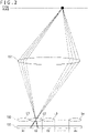
- FIG. 2 is a diagram for depicting a photographic optical system of the system depicted in FIG. 1 .
- a position detection system 10 includes a photographic lens 101, a microlens array 102, an event driven sensor (EDS) 103 that is an event-driven vision sensor, and an image processing device 200.
- the photographic lens 101 is a main lens for imaging an object to be targeted for position detection and includes a general imaging lens. As depicted in FIG.
- the microlens array 102 is arranged on an imaging surface of the photographic lens 101 and is obtained by two-dimensionally arraying a plurality of microlenses.
- Each microlens has, for example, a circular planar shape, and includes, for example, a solid lens, a liquid crystal lens, a diffraction lens, or the like.
- microlenses L1, L2, ..., Ln are one-dimensionally arrayed in the microlens array 12 depicted in FIG. 1 and FIG. 2 , but actually the microlenses are two-dimensionally arrayed.
- the light having passed through a first microlens L1 included in the microlens array 102 is guided to a first region A1 on a sensor array of the EDS 103, and the light having passed through a second microlens L2 is guided to a second region A2 on the sensor array of the EDS 103.
- the light having passed through the n-th microlens Ln is guided to an n-th region An on the sensor array of the EDS 103.
- n pieces of regions A1, A2, ..., An are arranged so as not to overlap with one another.
- m pieces of sensors are arranged in the respective regions A1, A2, ..., An on the sensor array. It should be noted that the number m of sensors corresponding to the respective regions may be constant or may be partially different.
- the EDS 103 is an example of a vision sensor that generates an event signal when the sensor detects a change in the intensity of light.
- the EDS 103 includes sensors, not depicted, configuring the sensor array and a processing circuit, not depicted, connected to the sensors.
- Each sensor includes a light receiving element and generates an event signal when detecting a change in the intensity of incident light, more specifically, a change in luminance (for example, occurring at an edge portion of an object). Since the sensor that has not detected the change in the intensity of incident light does not generate the event signal, the event signal is generated in the EDS 103 in a time-asynchronous manner.
- the event signal output via the processing circuit includes sensor identification information (for example, the position of a pixel), the polarity of a change in luminance (rising or falling), a time stamp, and the like.
- the EDS 103 generates the event signal for each sensor. Therefore, if the sensor identification information (for example, the position of a pixel) is associated with each of the regions A1, A2, ..., An on the sensor array in advance, it is possible to specify which of the microlenses L1, L2, ..., Ln in the microlens array 102 the generated event signal corresponds to. In addition, if the sensor identification information (for example, the position of a pixel) is associated with a position in each of the regions A1, A2, ..., An of the sensors in advance, it is possible to specify from which viewpoint the generated event signal has been observed.
- the sensor identification information for example, the position of a pixel
- the image processing device 200 includes functions of a reception unit 201, a position detection unit 202, and a movement estimation unit 203 that are implemented by a computer having, for example, a communication interface, a processor, and a memory and realized by the processor operating according to a program stored in the memory or received via the communication interface.
- a computer having, for example, a communication interface, a processor, and a memory and realized by the processor operating according to a program stored in the memory or received via the communication interface.
- the reception unit 201 receives the event signals from the EDS 103 in a wired or wireless manner. As described above, the event signals are generated by the sensors of the EDS 103.
- the sensors of the EDS 103 include sensors arranged in regions where each light is guided by at least two microlenses included in the microlens array 102, and the reception unit 201 receives each event signal generated by the sensor in each region.
- the position detection unit 202 detects the three-dimensional position of an event, that is, a change in the intensity of light (hereinafter, also referred to as a three-dimensional position where the event occurred or an event position), from the event signals received by the reception unit 201. More specifically, the position detection unit 202 detects the three-dimensional position where the event occurred by reconstructing the event signals from the sensors in the regions A1, A2, ..., An of the EDS 103 on the basis of the known positional relation between the photographic lens 101 and the microlens array 102.
- an event that is, a change in the intensity of light
- the position detection unit 202 treats the event signals from the sensors in the regions A1, A2, ..., An of the EDS 103 as information indicating a two-dimensional event position observed from m pieces of viewpoints, and detects the three-dimensional position where the event occurred by utilizing parallaxes among these viewpoints.
- the position detection unit 202 can detect the three-dimensional position where the event occurred if there are event signals generated by the respective sensors arranged in the regions (first and second regions) where each light is guided by at least two microlenses (first and second microlenses). Further, detection accuracy can be further improved by utilizing the event signals observed from three or more viewpoints mutually having parallaxes. Therefore, the position detection unit 202 may detect the three-dimensional position where the event occurred, on the basis of the event signals generated by the respective sensors arranged in the regions where each light is guided by three or more microlenses.
- the movement estimation unit 203 continuously acquires the detection result of the event position by the position detection unit 202 and estimates the movement of the event position on the basis of time-series detection results. For example, the movement estimation unit 203 may express the movement of the event position in a predetermined period by using a vector, on the basis of time-series changes in the three-dimensional position where the event occurred. Further, the movement estimation unit 203 may estimate the movement of the event position in the future from time-series changes in the past event position. For example, the movement of the event position in the future thus estimated can be utilized for, for example, the future position prediction of an object being present at the event position.
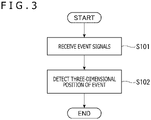
- FIG. 3 is a flowchart for depicting an example of a position detection method according to the embodiment of the present invention.
- the reception unit 201 of the image processing device 200 receives event signals generated by the sensors of the EDS 103 (Step S101).
- the event signals received at this time include an event signal necessary for specifying a two-dimensional event position observed from at least two viewpoints.
- the position detection unit 202 detects the three-dimensional position where the event occurred, on the basis of the event signals received in Step S101 (Step S102).
- the three-dimensional position of the event can be detected by obtaining information indicating the two-dimensional event position observed from at least two viewpoints.
- FIG. 4 is a flowchart for depicting another example of the position detection method according to the embodiment of the present invention.
- the reception unit 201 of the image processing device 200 receives event signals (Step S201), and the position detection unit 202 detects the three-dimensional position where the event occurred, on the basis of the received event signals (Step S202).
- the movement estimation unit 203 determines whether or not the number N of times of detection of the three-dimensional position is two or more (Step S203), and estimates the movement of the event position in a case where the number N is two or more (Step S204). As described above, the movement of the event position is estimated from changes in the three-dimensional position of the event detected twice or more.
- the EDS 103 since the EDS 103 detects a change in the intensity of incident light via the microlens array 102, the event position can be accurately detected at a high frame rate on the basis of the information of the occurrence position of the event observed from a plurality of viewpoints. Further, high prediction accuracy can be realized in, for example, the future position prediction of an object being present at the event position by estimating the event position on the basis of the time-series detection results of the event position. It is conceivable that the estimation result by the movement estimation unit 203 is used for, for example, avoidance motion control for an approaching object, control of a moving speed and a traveling direction according to an obstacle, and the like other than the above.
- the movement of the event position can be estimated at a high frame rate and with high prediction accuracy by a combination of the microlens array 102 and the EDS 103. Since the event position can be specified by using the EDS 103 without image processing and since the latency of processing for an approaching object or the like is low and it is only necessary to arrange a single EDS 103 corresponding to the microlens array 102, the same processing as a case in which, for example, a plurality of cameras for obtaining a plurality of viewpoint images is arranged can be realized with space-saving. Further, since it can be determined on the basis of the event signals generated by the EDS 103 that a change in the intensity of light occurred, no additional configuration or control such as infrared (IR) irradiation or an auxiliary light source is required.
- IR infrared
- the position detection system 10 described in the above example may be implemented in a single device, or may be dispersedly implemented in a plurality of devices.
- the entire position detection system 10 may be implemented in a robot, a drone, or a terminal device including a wearable terminal or the like, or the image processing device 200 may be dispersedly implemented in server devices.
- the microlens array 102 may be arranged away from the imaging surface of the photographic lens 101, and a change in the intensity of light may be detected by the EDS 103 via the microlens array 102 on the basis of a virtual image on the imaging surface of the photographic lens 101.
- each microlens configuring the microlens array 102 may have a uniform focal distance, or microlenses having different focal distances may be regularly or irregularly arranged to configure the microlens array 102.
Landscapes
- Engineering & Computer Science (AREA)
- Physics & Mathematics (AREA)
- General Physics & Mathematics (AREA)
- Multimedia (AREA)
- Signal Processing (AREA)
- Theoretical Computer Science (AREA)
- Computer Vision & Pattern Recognition (AREA)
- Spectroscopy & Molecular Physics (AREA)
- Computing Systems (AREA)
- Length Measuring Devices By Optical Means (AREA)
Abstract
Description
- The present invention relates to a position detection system, an image processing device, a position detection method, and a position detection program.
- An event-driven vision sensor in which a pixel having detected a change in the intensity of incident light generates a signal in a time-asynchronous manner has been known. The event-driven vision sensor is advantageous in that the event-driven vision sensor can operate at a low power and a high speed as compared with a frame-type vision sensor that scans all pixels at each predetermined cycle, specifically, an image sensor such as a charge coupled device (CCD) or a complementary metal oxide semiconductor (CMOS). A technique relating to such an event-driven vision sensor is described in, for example,
PTL 1 and PTL 2. -
- [PTL 1]
Japanese Translation of PCT for Patent No. 2014-535098 - [PTL 2]
Japanese Patent Laid-open No. 2018-85725 - However, regarding the event-driven vision sensor, the advantages as described above have been known, but it is difficult to say that utilization methods in combination with other devices have yet been sufficiently proposed.
- Accordingly, an object of the present invention is to provide a position detection system, an image processing device, a position detection method, and a position detection program that can obtain advantageous effects by using an event-driven vision sensor in combination with a microlens array.
- According to an aspect of the present invention, provided is a position detection system including an event-driven vision sensor that includes a sensor array including sensors each generating an event signal when a change in intensity of incident light is detected, a microlens array that includes at least first and second microlenses for guiding the light to first and second regions of the sensor array, respectively, and a terminal device that has a reception unit for receiving the event signal from the vision sensor, and a position detection unit for detecting a three-dimensional position of the change in the intensity of light, from the event signal generated by each sensor in the first region and the second region.
- According to another aspect of the present invention, provided is an image processing device including a reception unit that receives an event signal from an event-driven vision sensor including a sensor array including sensors each generating the event signal when a change in intensity of incident light is detected via a microlens array, and a position detection unit that detects a three-dimensional position of the change in the intensity of light, from the event signals. The microlens array includes at least first and second microlenses for guiding the light to first and second regions of the sensor array, respectively. The position detection unit detects the three-dimensional position, from the event signal generated by each sensor in the first region and the second region.
- According to still another aspect of the present invention, provided is a position detection method including a step of receiving an event signal from an event-driven vision sensor including a sensor array including sensors each generating the event signal when a change in intensity of incident light is detected via a microlens array, and a step of detecting a three-dimensional position of the change in the intensity of light, from the event signals. The microlens array includes at least first and second microlenses for guiding the light to first and second regions of the sensor array, respectively. In the step of detecting the three-dimensional position, the three-dimensional position is detected from the event signal generated by each sensor in the first region and the second region.
- According to still another aspect of the present invention, provided is a position detection program that causes a computer to realize a function of receiving an event signal from an event-driven vision sensor including a sensor array including sensors each generating the event signal when a change in intensity of incident light is detected via a microlens array, and a function of detecting a three-dimensional position of the change in the intensity of light, from the event signals. The microlens array includes at least first and second microlenses for guiding the light to first and second regions of the sensor array, respectively.
- The function of detecting the three-dimensional position detects the three-dimensional position, from the event signal generated by each sensor in the first region and the second region.
-
- [
FIG. 1 ]
FIG. 1 is a block diagram for depicting a schematic configuration of a system according to an embodiment of the present invention. - [
FIG. 2 ]
FIG. 2 is a diagram for depicting a photographic optical system of the system depicted inFIG. 1 . - [
FIG. 3 ]
FIG. 3 is a flowchart for depicting an example of a position detection method according to the embodiment of the present invention. - [
FIG. 4 ]
FIG. 4 is a flowchart for depicting another example of the position detection method according to the embodiment of the present invention. - Hereinafter, several embodiments of the present invention will be described in detail with reference to the accompanying drawings. It should be noted that, in the specification and the drawings, constitutional elements having substantially the same functional configurations will be denoted by the same reference signs, and duplicated description thereof will be omitted.
-
FIG. 1 is a block diagram for depicting a schematic configuration of a position detection system according to an embodiment of the present invention.FIG. 2 is a diagram for depicting a photographic optical system of the system depicted inFIG. 1 . As depicted inFIG. 1 , aposition detection system 10 includes aphotographic lens 101, amicrolens array 102, an event driven sensor (EDS) 103 that is an event-driven vision sensor, and animage processing device 200. Thephotographic lens 101 is a main lens for imaging an object to be targeted for position detection and includes a general imaging lens. As depicted inFIG. 2 , themicrolens array 102 is arranged on an imaging surface of thephotographic lens 101 and is obtained by two-dimensionally arraying a plurality of microlenses. Each microlens has, for example, a circular planar shape, and includes, for example, a solid lens, a liquid crystal lens, a diffraction lens, or the like. It should be noted that microlenses L1, L2, ..., Ln are one-dimensionally arrayed in the microlens array 12 depicted inFIG. 1 andFIG. 2 , but actually the microlenses are two-dimensionally arrayed. - As depicted in
FIG. 2 , among light incident on thephotographic lens 101, the light having passed through a first microlens L1 included in themicrolens array 102 is guided to a first region A1 on a sensor array of theEDS 103, and the light having passed through a second microlens L2 is guided to a second region A2 on the sensor array of theEDS 103. As similar to the above, the light having passed through the n-th microlens Ln is guided to an n-th region An on the sensor array of theEDS 103. In themicrolens array 102 and the EDS 103, n pieces of regions A1, A2, ..., An are arranged so as not to overlap with one another. In theEDS 103, m pieces of sensors are arranged in the respective regions A1, A2, ..., An on the sensor array. It should be noted that the number m of sensors corresponding to the respective regions may be constant or may be partially different. - The EDS 103 is an example of a vision sensor that generates an event signal when the sensor detects a change in the intensity of light. The EDS 103 includes sensors, not depicted, configuring the sensor array and a processing circuit, not depicted, connected to the sensors. Each sensor includes a light receiving element and generates an event signal when detecting a change in the intensity of incident light, more specifically, a change in luminance (for example, occurring at an edge portion of an object). Since the sensor that has not detected the change in the intensity of incident light does not generate the event signal, the event signal is generated in the
EDS 103 in a time-asynchronous manner. The event signal output via the processing circuit includes sensor identification information (for example, the position of a pixel), the polarity of a change in luminance (rising or falling), a time stamp, and the like. - Here, the EDS 103 generates the event signal for each sensor. Therefore, if the sensor identification information (for example, the position of a pixel) is associated with each of the regions A1, A2, ..., An on the sensor array in advance, it is possible to specify which of the microlenses L1, L2, ..., Ln in the
microlens array 102 the generated event signal corresponds to. In addition, if the sensor identification information (for example, the position of a pixel) is associated with a position in each of the regions A1, A2, ..., An of the sensors in advance, it is possible to specify from which viewpoint the generated event signal has been observed. - The
image processing device 200 includes functions of areception unit 201, aposition detection unit 202, and amovement estimation unit 203 that are implemented by a computer having, for example, a communication interface, a processor, and a memory and realized by the processor operating according to a program stored in the memory or received via the communication interface. Hereinafter, the function of each unit will be further described. - The
reception unit 201 receives the event signals from the EDS 103 in a wired or wireless manner. As described above, the event signals are generated by the sensors of theEDS 103. The sensors of the EDS 103 include sensors arranged in regions where each light is guided by at least two microlenses included in themicrolens array 102, and thereception unit 201 receives each event signal generated by the sensor in each region. - The
position detection unit 202 detects the three-dimensional position of an event, that is, a change in the intensity of light (hereinafter, also referred to as a three-dimensional position where the event occurred or an event position), from the event signals received by thereception unit 201. More specifically, theposition detection unit 202 detects the three-dimensional position where the event occurred by reconstructing the event signals from the sensors in the regions A1, A2, ..., An of theEDS 103 on the basis of the known positional relation between thephotographic lens 101 and themicrolens array 102. In other words, theposition detection unit 202 treats the event signals from the sensors in the regions A1, A2, ..., An of theEDS 103 as information indicating a two-dimensional event position observed from m pieces of viewpoints, and detects the three-dimensional position where the event occurred by utilizing parallaxes among these viewpoints. - Here, since the three-dimensional position can be detected from the event signals observed from two or more viewpoints mutually having parallaxes, the
position detection unit 202 can detect the three-dimensional position where the event occurred if there are event signals generated by the respective sensors arranged in the regions (first and second regions) where each light is guided by at least two microlenses (first and second microlenses). Further, detection accuracy can be further improved by utilizing the event signals observed from three or more viewpoints mutually having parallaxes. Therefore, theposition detection unit 202 may detect the three-dimensional position where the event occurred, on the basis of the event signals generated by the respective sensors arranged in the regions where each light is guided by three or more microlenses. - The
movement estimation unit 203 continuously acquires the detection result of the event position by theposition detection unit 202 and estimates the movement of the event position on the basis of time-series detection results. For example, themovement estimation unit 203 may express the movement of the event position in a predetermined period by using a vector, on the basis of time-series changes in the three-dimensional position where the event occurred. Further, themovement estimation unit 203 may estimate the movement of the event position in the future from time-series changes in the past event position. For example, the movement of the event position in the future thus estimated can be utilized for, for example, the future position prediction of an object being present at the event position. -
FIG. 3 is a flowchart for depicting an example of a position detection method according to the embodiment of the present invention. In the illustrated example, thereception unit 201 of theimage processing device 200 receives event signals generated by the sensors of the EDS 103 (Step S101). The event signals received at this time include an event signal necessary for specifying a two-dimensional event position observed from at least two viewpoints. Next, theposition detection unit 202 detects the three-dimensional position where the event occurred, on the basis of the event signals received in Step S101 (Step S102). As described above, the three-dimensional position of the event can be detected by obtaining information indicating the two-dimensional event position observed from at least two viewpoints. -
FIG. 4 is a flowchart for depicting another example of the position detection method according to the embodiment of the present invention. In the illustrated example, as similar to the example ofFIG. 3 , thereception unit 201 of theimage processing device 200 receives event signals (Step S201), and theposition detection unit 202 detects the three-dimensional position where the event occurred, on the basis of the received event signals (Step S202). Further, themovement estimation unit 203 determines whether or not the number N of times of detection of the three-dimensional position is two or more (Step S203), and estimates the movement of the event position in a case where the number N is two or more (Step S204). As described above, the movement of the event position is estimated from changes in the three-dimensional position of the event detected twice or more. - In the embodiment of the present invention as described above, since the
EDS 103 detects a change in the intensity of incident light via themicrolens array 102, the event position can be accurately detected at a high frame rate on the basis of the information of the occurrence position of the event observed from a plurality of viewpoints. Further, high prediction accuracy can be realized in, for example, the future position prediction of an object being present at the event position by estimating the event position on the basis of the time-series detection results of the event position. It is conceivable that the estimation result by themovement estimation unit 203 is used for, for example, avoidance motion control for an approaching object, control of a moving speed and a traveling direction according to an obstacle, and the like other than the above. - In addition, in the embodiment of the present invention, the movement of the event position can be estimated at a high frame rate and with high prediction accuracy by a combination of the
microlens array 102 and theEDS 103. Since the event position can be specified by using theEDS 103 without image processing and since the latency of processing for an approaching object or the like is low and it is only necessary to arrange asingle EDS 103 corresponding to themicrolens array 102, the same processing as a case in which, for example, a plurality of cameras for obtaining a plurality of viewpoint images is arranged can be realized with space-saving. Further, since it can be determined on the basis of the event signals generated by theEDS 103 that a change in the intensity of light occurred, no additional configuration or control such as infrared (IR) irradiation or an auxiliary light source is required. - It should be noted that the
position detection system 10 described in the above example may be implemented in a single device, or may be dispersedly implemented in a plurality of devices. For example, the entireposition detection system 10 may be implemented in a robot, a drone, or a terminal device including a wearable terminal or the like, or theimage processing device 200 may be dispersedly implemented in server devices. - In addition, in the
position detection system 10 described in the above example, the example in which themicrolens array 102 is arranged on the imaging surface of thephotographic lens 101 has been depicted, but other arrangements may be employed. For example, themicrolens array 102 may be arranged away from the imaging surface of thephotographic lens 101, and a change in the intensity of light may be detected by theEDS 103 via themicrolens array 102 on the basis of a virtual image on the imaging surface of thephotographic lens 101. - In addition, regarding the
microlens array 102 of theposition detection system 10 described in the above example, if each microlens is associated with a region on the sensor array of theEDS 103, each microlens configuring themicrolens array 102 may have a uniform focal distance, or microlenses having different focal distances may be regularly or irregularly arranged to configure themicrolens array 102. - Although several embodiments of the present invention have been described above in detail with reference to the accompanying drawings, the present invention is not limited to such examples. It is clear that a person ordinarily skilled in the art to which the present invention belongs can perceive various change examples and modification examples within the scope of the technical idea described in the claims, and it can be understood that these obviously belong to the technical range of the present invention.
-
- 10: Position detection system
- 101: Photographic lens
- 102: Microlens array
- 103: EDS
- 200: Image processing device
- 201: Reception unit
- 202: Position detection unit
- 203: Movement estimation unit
Claims (5)
- A position detection system comprising:an event-driven vision sensor that includes a sensor array including sensors each generating an event signal when a change in intensity of incident light is detected;a microlens array that includes at least first and second microlenses for guiding the light to first and second regions of the sensor array, respectively; anda terminal device that hasa reception unit for receiving the event signal from the vision sensor, anda position detection unit for detecting a three-dimensional position of the change in the intensity of light, from the event signal generated by each sensor in the first region and the second region.
- An image processing device comprising:a reception unit that receives an event signal from an event-driven vision sensor including a sensor array including sensors each generating the event signal when a change in intensity of incident light is detected via a microlens array; anda position detection unit that detects a three-dimensional position of the change in the intensity of light, from the event signals,wherein the microlens array includes at least first and second microlenses for guiding the light to first and second regions of the sensor array, respectively, andthe position detection unit detects the three-dimensional position, from the event signal generated by each sensor in the first region and the second region.
- The image processing device according to claim 2, further comprising:
a movement estimation unit that continuously acquires a detection result by the position detection unit and estimates a movement of the three-dimensional position on a basis of time-series detection results. - A position detection method comprising:a step of receiving an event signal from an event-driven vision sensor including a sensor array including sensors each generating the event signal when a change in intensity of incident light is detected via a microlens array; anda step of detecting a three-dimensional position of the change in the intensity of light, from the event signals,wherein, the microlens array includes at least first and second microlenses for guiding the light to first and second regions of the sensor array, respectively, and,in the step of detecting the three-dimensional position, the three-dimensional position is detected from the event signal generated by each sensor in the first region and the second region.
- A position detection program that causes a computer to realize:a function of receiving an event signal from an event-driven vision sensor including a sensor array including sensors each generating the event signal when a change in intensity of incident light is detected via a microlens array; anda function of detecting a three-dimensional position of the change in the intensity of light, from the event signals,wherein the microlens array includes at least first and second microlenses for guiding the light to first and second regions of the sensor array, respectively, andthe function of detecting the three-dimensional position detects the three-dimensional position, from the event signal generated by each sensor in the first region and the second region.
Applications Claiming Priority (1)
| Application Number | Priority Date | Filing Date | Title |
|---|---|---|---|
| PCT/JP2019/024797 WO2020255399A1 (en) | 2019-06-21 | 2019-06-21 | Position detection system, image processing device, position detection method, and position detection program |
Publications (2)
| Publication Number | Publication Date |
|---|---|
| EP3988893A1 true EP3988893A1 (en) | 2022-04-27 |
| EP3988893A4 EP3988893A4 (en) | 2023-01-11 |
Family
ID=74040444
Family Applications (1)
| Application Number | Title | Priority Date | Filing Date |
|---|---|---|---|
| EP19933874.0A Withdrawn EP3988893A4 (en) | 2019-06-21 | 2019-06-21 | POSITION DETECTION SYSTEM, IMAGE PROCESSING DEVICE, POSITION DETECTION METHOD AND POSITION DETECTION PROGRAM |
Country Status (6)
| Country | Link |
|---|---|
| US (1) | US12106507B2 (en) |
| EP (1) | EP3988893A4 (en) |
| JP (1) | JPWO2020255399A1 (en) |
| KR (1) | KR20220023979A (en) |
| CN (1) | CN113994168A (en) |
| WO (1) | WO2020255399A1 (en) |
Cited By (1)
| Publication number | Priority date | Publication date | Assignee | Title |
|---|---|---|---|---|
| DE102023123170A1 (en) * | 2023-08-29 | 2025-03-06 | Deutsches Zentrum für Luft- und Raumfahrt e.V. | Camera device and method for extracting depth information using a camera device |
Families Citing this family (9)
| Publication number | Priority date | Publication date | Assignee | Title |
|---|---|---|---|---|
| JP7826332B2 (en) | 2020-12-14 | 2026-03-09 | サマー ロボティックス インコーポレイテッド | Object perception based on surface detection and surface motion detection |
| WO2023096873A1 (en) | 2021-11-28 | 2023-06-01 | Summer Robotics, Inc. | Association of concurrent tracks across multiple views |
| CN114401358A (en) * | 2022-01-28 | 2022-04-26 | 苏州华兴源创科技股份有限公司 | Event camera imaging device and method and event camera |
| WO2023164064A1 (en) | 2022-02-27 | 2023-08-31 | Summer Robotics, Inc. | Association of concurrent tracks using graph crossings |
| WO2023188183A1 (en) * | 2022-03-30 | 2023-10-05 | 株式会社ソニー・インタラクティブエンタテインメント | Information processing device, system, information processing method, information processing program, and computer system |
| US12401905B2 (en) | 2022-07-14 | 2025-08-26 | Summer Robotics, Inc. | Foveated robotic vision system |
| US20240040274A1 (en) * | 2022-07-28 | 2024-02-01 | Summer Robotics, Inc. | Folded single sensor 3-d capture system |
| US11974055B1 (en) | 2022-10-17 | 2024-04-30 | Summer Robotics, Inc. | Perceiving scene features using event sensors and image sensors |
| US12416804B1 (en) | 2024-05-08 | 2025-09-16 | Summer Robotics, Inc. | Kaleidoscopic laser beam projection system |
Family Cites Families (25)
| Publication number | Priority date | Publication date | Assignee | Title |
|---|---|---|---|---|
| JPH08280864A (en) * | 1995-04-12 | 1996-10-29 | Fuji Heavy Ind Ltd | Ball game exercising machine |
| JP5375531B2 (en) | 2009-11-06 | 2013-12-25 | 株式会社リコー | Distance image acquisition device and distance image acquisition processing method |
| KR101880998B1 (en) | 2011-10-14 | 2018-07-24 | 삼성전자주식회사 | Apparatus and Method for motion recognition with event base vision sensor |
| US10057498B1 (en) * | 2013-03-15 | 2018-08-21 | Cognex Corporation | Light field vision system camera and methods for using the same |
| US10863098B2 (en) | 2013-06-20 | 2020-12-08 | Microsoft Technology Licensing. LLC | Multimodal image sensing for region of interest capture |
| JP2015084089A (en) | 2013-09-19 | 2015-04-30 | 株式会社東芝 | Microlens array for solid state image pickup element, solid state image pickup element, imaging device and lens unit |
| CN104864849B (en) * | 2014-02-24 | 2017-12-26 | 电信科学技术研究院 | Vision navigation method and device and robot |
| US9952323B2 (en) * | 2014-04-07 | 2018-04-24 | Samsung Electronics Co., Ltd. | High resolution, high frame rate, low power image sensor |
| JP6648411B2 (en) * | 2014-05-19 | 2020-02-14 | 株式会社リコー | Processing device, processing system, processing program and processing method |
| JP2016001464A (en) * | 2014-05-19 | 2016-01-07 | 株式会社リコー | PROCESSING DEVICE, PROCESSING SYSTEM, PROCESSING PROGRAM, AND PROCESSING METHOD |
| US9383548B2 (en) | 2014-06-11 | 2016-07-05 | Olympus Corporation | Image sensor for depth estimation |
| US9883122B2 (en) | 2014-09-16 | 2018-01-30 | Qualcomm Incorporated | Event-based down sampling |
| WO2016109355A1 (en) | 2014-12-23 | 2016-07-07 | Bribbla Dynamics Llc | Optical inspection system and method including accounting for variations of optical path length within a sample |
| US10277888B2 (en) | 2015-01-16 | 2019-04-30 | Qualcomm Incorporated | Depth triggered event feature |
| EP3104595A1 (en) | 2015-06-08 | 2016-12-14 | Thomson Licensing | Light field imaging device |
| US10341634B2 (en) | 2016-01-29 | 2019-07-02 | Samsung Electronics Co., Ltd. | Method and apparatus for acquiring image disparity |
| CN105807550B (en) | 2016-03-02 | 2019-04-23 | 深圳大学 | Inversion ultra-high-speed imaging method |
| US20180146149A1 (en) | 2016-11-21 | 2018-05-24 | Samsung Electronics Co., Ltd. | Event-based sensor, user device including the same, and operation method of the same |
| US11145077B2 (en) | 2017-02-06 | 2021-10-12 | Photonic Sensors & Algorithms, S.L. | Device and method for obtaining depth information from a scene |
| US20210126025A1 (en) * | 2017-05-31 | 2021-04-29 | Monash University | Imaging Method and Apparatus |
| CN107302695A (en) * | 2017-05-31 | 2017-10-27 | 天津大学 | A kind of electronics compound eye system based on bionic visual mechanism |
| WO2019012660A1 (en) | 2017-07-13 | 2019-01-17 | オリンパス株式会社 | Image processing device and light field imaging device |
| US10347678B2 (en) | 2017-11-16 | 2019-07-09 | Visera Technologies Company Limited | Image sensor with shifted microlens array |
| US10706564B2 (en) * | 2018-04-11 | 2020-07-07 | Wisconsin Alumni Research Foundation | Systems, methods, and media for determining object motion in three dimensions from light field image data |
| US11143879B2 (en) * | 2018-05-25 | 2021-10-12 | Samsung Electronics Co., Ltd. | Semi-dense depth estimation from a dynamic vision sensor (DVS) stereo pair and a pulsed speckle pattern projector |
-
2019
- 2019-06-21 US US17/595,805 patent/US12106507B2/en active Active
- 2019-06-21 CN CN201980097517.8A patent/CN113994168A/en active Pending
- 2019-06-21 JP JP2021528617A patent/JPWO2020255399A1/ja active Pending
- 2019-06-21 KR KR1020217040236A patent/KR20220023979A/en not_active Withdrawn
- 2019-06-21 WO PCT/JP2019/024797 patent/WO2020255399A1/en not_active Ceased
- 2019-06-21 EP EP19933874.0A patent/EP3988893A4/en not_active Withdrawn
Cited By (1)
| Publication number | Priority date | Publication date | Assignee | Title |
|---|---|---|---|---|
| DE102023123170A1 (en) * | 2023-08-29 | 2025-03-06 | Deutsches Zentrum für Luft- und Raumfahrt e.V. | Camera device and method for extracting depth information using a camera device |
Also Published As
| Publication number | Publication date |
|---|---|
| US12106507B2 (en) | 2024-10-01 |
| US20220222845A1 (en) | 2022-07-14 |
| WO2020255399A1 (en) | 2020-12-24 |
| JPWO2020255399A1 (en) | 2020-12-24 |
| EP3988893A4 (en) | 2023-01-11 |
| CN113994168A (en) | 2022-01-28 |
| KR20220023979A (en) | 2022-03-03 |
Similar Documents
| Publication | Publication Date | Title |
|---|---|---|
| US12106507B2 (en) | Position detection system, image processing device, position detection method, and position detection program | |
| US20260036696A1 (en) | Sensor fusion system, synchronization control apparatus, and synchronization control method | |
| US9479760B2 (en) | Solid state imaging device, calculating device, and calculating program | |
| CN103477186B (en) | Stereo camera | |
| KR102472156B1 (en) | Electronic Device and the Method for Generating Depth Information thereof | |
| JP2007116208A (en) | Compound eye imaging apparatus | |
| JP2015049200A (en) | Measuring device, measuring method, and measuring program | |
| WO2012060564A1 (en) | 3d camera | |
| WO2020114595A1 (en) | Object targeting | |
| KR20200022390A (en) | Solid State Imaging Devices and Electronic Devices | |
| CN112602117A (en) | Image processing apparatus and three-dimensional measurement system | |
| KR20220024011A (en) | Sensor control device, sensor control method and program | |
| US20210286082A1 (en) | Distance measuring device and distance measuring device control method | |
| EP3671277A1 (en) | 3d imaging apparatus and method | |
| CN112714900A (en) | Display screen operation method, electronic device and readable storage medium | |
| EP3389256B1 (en) | Method and device for processing image | |
| CN114667729B (en) | Multi-aperture zoom digital camera and its use method | |
| US11418707B2 (en) | Electronic device and notification method | |
| KR20240127376A (en) | Depth sensor device and method for operating the depth sensor device | |
| JP2006322795A (en) | Image processing device, image processing method and image processing program | |
| WO2023188183A1 (en) | Information processing device, system, information processing method, information processing program, and computer system | |
| US10628697B2 (en) | Object approach detection device and object approach detection method | |
| EP4431869A1 (en) | Depth sensor device and method for operating a depth sensor device | |
| CN114035335B (en) | Display device, control method thereof, and display system | |
| JP7311597B2 (en) | System, position detection device, position detection method and program |
Legal Events
| Date | Code | Title | Description |
|---|---|---|---|
| STAA | Information on the status of an ep patent application or granted ep patent |
Free format text: STATUS: THE INTERNATIONAL PUBLICATION HAS BEEN MADE |
|
| PUAI | Public reference made under article 153(3) epc to a published international application that has entered the european phase |
Free format text: ORIGINAL CODE: 0009012 |
|
| STAA | Information on the status of an ep patent application or granted ep patent |
Free format text: STATUS: REQUEST FOR EXAMINATION WAS MADE |
|
| 17P | Request for examination filed |
Effective date: 20211130 |
|
| AK | Designated contracting states |
Kind code of ref document: A1 Designated state(s): AL AT BE BG CH CY CZ DE DK EE ES FI FR GB GR HR HU IE IS IT LI LT LU LV MC MK MT NL NO PL PT RO RS SE SI SK SM TR |
|
| DAV | Request for validation of the european patent (deleted) | ||
| DAX | Request for extension of the european patent (deleted) | ||
| A4 | Supplementary search report drawn up and despatched |
Effective date: 20221209 |
|
| RIC1 | Information provided on ipc code assigned before grant |
Ipc: H04N 13/00 20180101ALI20221205BHEP Ipc: H04N 13/232 20180101ALI20221205BHEP Ipc: H04N 5/369 20110101ALI20221205BHEP Ipc: G01B 11/00 20060101AFI20221205BHEP |
|
| STAA | Information on the status of an ep patent application or granted ep patent |
Free format text: STATUS: THE APPLICATION IS DEEMED TO BE WITHDRAWN |
|
| 18D | Application deemed to be withdrawn |
Effective date: 20230714 |