EP3988877A1 - Refrigeration appliance with lighting module - Google Patents
Refrigeration appliance with lighting module Download PDFInfo
- Publication number
- EP3988877A1 EP3988877A1 EP21201641.4A EP21201641A EP3988877A1 EP 3988877 A1 EP3988877 A1 EP 3988877A1 EP 21201641 A EP21201641 A EP 21201641A EP 3988877 A1 EP3988877 A1 EP 3988877A1
- Authority
- EP
- European Patent Office
- Prior art keywords
- decorative
- mounting slot
- refrigeration appliance
- decorative strip
- lighting module
- Prior art date
- Legal status (The legal status is an assumption and is not a legal conclusion. Google has not performed a legal analysis and makes no representation as to the accuracy of the status listed.)
- Pending
Links
Images



Classifications
-
- F—MECHANICAL ENGINEERING; LIGHTING; HEATING; WEAPONS; BLASTING
- F21—LIGHTING
- F21V—FUNCTIONAL FEATURES OR DETAILS OF LIGHTING DEVICES OR SYSTEMS THEREOF; STRUCTURAL COMBINATIONS OF LIGHTING DEVICES WITH OTHER ARTICLES, NOT OTHERWISE PROVIDED FOR
- F21V33/00—Structural combinations of lighting devices with other articles, not otherwise provided for
- F21V33/0004—Personal or domestic articles
- F21V33/0044—Household appliances, e.g. washing machines or vacuum cleaners
-
- F—MECHANICAL ENGINEERING; LIGHTING; HEATING; WEAPONS; BLASTING
- F25—REFRIGERATION OR COOLING; COMBINED HEATING AND REFRIGERATION SYSTEMS; HEAT PUMP SYSTEMS; MANUFACTURE OR STORAGE OF ICE; LIQUEFACTION SOLIDIFICATION OF GASES
- F25D—REFRIGERATORS; COLD ROOMS; ICE-BOXES; COOLING OR FREEZING APPARATUS NOT OTHERWISE PROVIDED FOR
- F25D27/00—Lighting arrangements
-
- F—MECHANICAL ENGINEERING; LIGHTING; HEATING; WEAPONS; BLASTING
- F25—REFRIGERATION OR COOLING; COMBINED HEATING AND REFRIGERATION SYSTEMS; HEAT PUMP SYSTEMS; MANUFACTURE OR STORAGE OF ICE; LIQUEFACTION SOLIDIFICATION OF GASES
- F25D—REFRIGERATORS; COLD ROOMS; ICE-BOXES; COOLING OR FREEZING APPARATUS NOT OTHERWISE PROVIDED FOR
- F25D23/00—General constructional features
- F25D23/06—Walls
- F25D23/065—Details
- F25D23/066—Liners
-
- F—MECHANICAL ENGINEERING; LIGHTING; HEATING; WEAPONS; BLASTING
- F25—REFRIGERATION OR COOLING; COMBINED HEATING AND REFRIGERATION SYSTEMS; HEAT PUMP SYSTEMS; MANUFACTURE OR STORAGE OF ICE; LIQUEFACTION SOLIDIFICATION OF GASES
- F25D—REFRIGERATORS; COLD ROOMS; ICE-BOXES; COOLING OR FREEZING APPARATUS NOT OTHERWISE PROVIDED FOR
- F25D2400/00—General features of, or devices for refrigerators, cold rooms, ice-boxes, or for cooling or freezing apparatus not covered by any other subclass
- F25D2400/18—Aesthetic features
Definitions
- Embodiments of the present utility model relate to a refrigeration appliance with a lighting module.
- a refrigeration appliance is provided with a lighting module configured to illuminate a storage compartment. While an illuminating effect of the lighting module is considered, a visual effect of the lighting module in the storage compartment is usually ignored.
- An objective of embodiments of the present utility model is to provide an improved lighting module for a refrigeration appliance and a refrigeration appliance with such a lighting module.
- Another objective of the embodiments of the present utility model is to provide a refrigeration appliance that benefits a visual effect of a lighting module in a storage compartment.
- the embodiments of the present utility model relate to a refrigeration appliance.
- the refrigeration appliance includes a storage compartment provided with a front opening, the storage compartment including a top wall and a mounting slot located in the top wall; and a lighting module fastened in the mounting slot.
- the lighting module includes a front wall facing the front opening.
- the front wall includes a main part and a decorative strip connected to the main part. An upper end of the decorative strip extends into the mounting slot.
- a connecting seam between an upper end portion of the decorative strip and the main part is located in the mounting slot, and is covered by a front inner wall surface of the mounting slot in a longitudinal direction of the storage compartment.
- a front surface of the upper end portion extends in a vertical direction and/or is parallel to the front inner wall surface of the mounting slot.
- the decorative strip includes a decorative portion sloping from top to bottom. The upper end portion is connected to an upper end of the decorative portion.
- an intersection ridge between the upper end portion and the decorative portion is located above an edge part, surrounding the mounting slot, of a liner of the storage compartment.
- the decorative strip includes a lower end portion and the decorative portion.
- the lower end portion is connected to a lower end of the decorative portion, and bends backward from the decorative portion.
- a connecting seam between the lower end portion and the main part is completely located behind a rear surface of the decorative portion.
- a rear side of the decorative strip is provided with a positioning portion protruding toward the main part.
- the main part is provided with a corresponding recess.
- the positioning portion is located in the recess to position the decorative strip.
- the lighting module includes a front hook configured to connect to a slot in the mounting slot in a snap-fit manner.
- the front hook is connected to the slot at a position above and behind the decorative strip.
- the mounting slot is constructed with a step form at a position near the entrance and is therefore provided with a concave portion.
- the decorative strip extends into the concave portion.
- the lighting module includes a housing.
- the housing includes a frame provided with a light outlet and a cover connected to the frame.
- the frame or the cover is provided with a snap-fit connection structure connected to the mounting slot in a snap-fit manner.
- the decorative strip is connected to the frame.
- the decorative strip is made of metal or a plastic base material provided with a metallic decorative layer thereon.
- a refrigeration appliance 100 includes a main body 108.
- the main body 108 may be provided with a storage compartment 101 having a front opening 10.
- the storage compartment 101 may be selectively opened or closed by a door 102.
- the storage compartment 101 includes a top wall 103, a pair of side walls (not marked), and a rear wall (not shown).
- the rear wall of the storage compartment 101 faces the front opening 10. At least some of these inner walls may be defined by a liner 109 of the main body 108.
- the refrigeration appliance 100 includes a lighting module 1 configured to illuminate the storage compartment 101.
- the lighting module 1 is reachable through the storage compartment 101.
- the refrigeration appliance 100 includes a mounting slot 110 for mounting the lighting module 1.
- the mounting slot 110 may be formed by a mounting shell mounted along a through hole of the liner 109 and joined to a thermal insulation material in the main body 108.
- the mounting slot 110 is formed by the liner 109 denting in a direction away from the storage compartment 101.
- the lighting module 1 includes a housing 2.
- the housing 2 is provided with a first connection structure 21 for connecting to the mounting slot 110, to detachably fasten the lighting module 1 on a box body 102.
- the first connection structure 21 may be provided with a plurality of hooks 211 and 212. The hooks 211 and 212 cooperate with a slot 111 in the mounting slot 110 to fasten the lighting module 1 on the main body 108.
- the lighting module 1 may be disposed on the top wall 103. It may be easily understood that, in another embodiment, the lighting module 1 may be alternatively disposed on the side wall or the rear wall of the storage compartment 101.
- the housing 2 is provided with a light outlet 221. Light enters the storage compartment 101 through the light outlet 221. As shown in FIG. 1 , the light outlet 221 may be substantially horizontally disposed at the top of the storage compartment 101, and the light outlet 221 is located at the bottom of the housing 2.
- the housing 2 may include a front wall 25 facing the front opening 10.
- the front wall 25 When mounted on the top wall 103 of the storage compartment 101, the front wall 25 is inclined from top to bottom, and has a lower part closer to the rear than an upper part. This makes a front surface of the front wall 25 more easily visible to a user under the top wall 103.
- the front wall 25 includes a main part 251 and a decorative strip 252 fastened on a front side of the main part 251.
- the decorative strip 252 may be bonded to the main part 251 by an adhesion apparatus 258.
- the decorative strip 252 may be made of metal or a plastic base material provided with a metallic decorative layer thereon.
- the mounting slot 110 may be constructed with a step form at a position near the entrance and is therefore provided with a relatively shallow concave portion 112.
- the upper end of the decorative strip 252 extends into the concave portion 112.
- the front hook 211 of the first connection structure 21 may be connected to the slot 111 above and behind the decorative strip 252.
- a rear end of the lighting module 1 may be placed in the mounting slot 110 first, to cause the rear hook 212 of the first connection structure 21 to abut against a rear slot in the mounting slot 110 to form a pivot. Then, the lighting module 1 is rotated around the pivot, to press the front hook 211 into the mounting slot 110 to connect to the slot 111 in a snap-fit manner, so as to complete mounting of the lighting module 1.
- the front hook 211 of the first connection structure 21 is connected to the slot 111 above and behind the decorative strip 252, and the upper end of the decorative strip 252 is located in the relatively shallow concave portion 112, a possibility that the decorative strip 252 severely interferes with the liner 109 and causes the liner to fall off during the mounting of the lighting module 1 is significantly reduced.
- the main part 251 of the front wall 25 may be provided with a pit 2510 for accommodating the decorative strip 252, and the decorative strip 252 is located in the pit 2510.
- a connecting seam 253 exposed to the front surface of the front wall 25 is provided between upper ends of the main part 251 and the decorative strip 252.
- the connecting seam 253 is completely located in the mounting slot 110, and is completely covered by a front inner wall surface of the mounting slot 110 in a longitudinal direction X of the storage compartment 101.
- the connecting seam 253 is completely located in the mounting slot 110, and is completely covered by a front inner wall surface of the mounting slot 110 in a longitudinal direction X of the storage compartment 101. Therefore, there may be a better visual transition between a front side of the lighting module 1 and the liner 109.
- the decorative strip 252 may include an upper end portion 255 located at an upper end, a lower end portion 254 located at a lower end, and a decorative portion 256 located between the upper end portion 255 and the lower end portion 254.
- a front surface of the decorative portion 256 is a bevel sloping from top to bottom. At least the front surface of the decorative portion 256 is mostly visible to a user.
- An angle is formed between the upper end portion 255 and the decorative portion 256.
- a front surface of the upper end portion 255 may extend in a vertical direction and/or may be parallel to the front inner wall surface of the mounting slot 110.
- An intersection ridge 259 between the upper end portion 255 and the decorative portion 256 may be located above an edge part 1091, surrounding the mounting slot 110, of the liner 109. This helps to obtain simple design.
- the lower end portion 254 is connected to a lower end of the decorative portion 256.
- the lower end portion 254 bends from the decorative portion 256 and extends backward, so that a connecting seam between the lower end portion 254 and the main part 251 is completely located behind a rear surface of the decorative portion 256 in the longitudinal direction X of the storage compartment 101.
- At least a part of a lower surface of the front wall 25 is formed by the lower end portion 254. This helps to improve a decorative effect.
- a rear side of the decorative strip 252 may be provided with a positioning portion 257 protruding toward the main part 251.
- the main part 251 is provided with a corresponding recess (not marked).
- the positioning portion 257 is located in the recess to position the decorative strip 252.
- the housing 2 may include a frame 22 and a cover 23.
- a light source 3 of the lighting module 1 is located in an accommodating space 26 defined by the frame 22 and the cover 23.
- the frame 22 may be made of opaque plastic.
- the frame 22 is provided with a light outlet 221 in a wall exposed to the storage compartment 101. Light illuminates the storage compartment 101 through the light outlet 221.
- the lighting module 1 includes a light guide plate 4.
- the light guide plate 4 is located between the light outlet 221 and the cover 23.
- the light guide plate 4 is adapted to guide light from the light source 3 toward the light outlet 221.
- the light guide plate 4 may include a plurality of lattice points. Light in the light guide plate 4 may concentrate again at the lattice points.
- the lattice points may be formed through printing or by concave/convex point portions.
- the light source 3 is located in the housing 2.
- the light source 3 may include a plurality of light emitting elements 31 and a substrate 32 bearing the light emitting elements 31.
- the light emitting elements 31 may be light-emitting diodes.
- the light guide plate 4 may cover the light outlet 221 completely and may be basically parallel to the light outlet 221.
- the light guide plate 4 includes a first end surface 41 facing the light source 3 and a second end surface 42 opposite to the first end surface 41. Light emitted from the light source 3 enters the light guide plate 4 through the first end surface 41.
- the lighting module 1 may further include a diffusion board 5 located between the light guide plate 4 and the light outlet 221, to diffuse light from the light guide plate 4 uniformly, so that light from the light outlet 221 is basically uniform.
- the lighting module 1 may further include a reflecting layer 6 located between the light guide plate 4 and the cover 23, to cause light to illuminate the diffusion board 5 in a manner as close to total reflection as possible.
- the reflecting layer 6, the light guide plate 4, and the diffusion board 5 may be disposed adjacent to each other in sequence between the cover 23 and the light outlet 221.
- the light guide plate 4 is likely to expand in an environment with relatively high temperature or humidity and contract in an environment with relatively low temperature or humidity. Expansion caused by temperature change is reversible while expansion caused by humidity change is not.
- the lighting module 1 is mounted in storage compartments of the refrigeration appliance 100 with different temperature or humidity, the light guide plate 4 may change in size to different degrees.
- lighting quality of the same lighting module 1 varies in the different storage compartments. For example, lighting quality of the lighting module in a refrigerating compartment and lighting quality of the lighting module in a freezing compartment are different after a particular period. Lighting quality of the lighting module 1 in the same storage compartment may also be unstable when temperature in the storage compartment is set to different temperature zones.
- the lighting module 1 may include a first elastic member 7.
- the first elastic member 7 may be sandwiched between the second end surface 42 of the light guide plate 4 and the housing 2 to apply a force toward the light source 3 to the light guide plate 4, so that regardless of a storage compartment in which the lighting module 1 is mounted or even though the lighting module 1 is mounted in a storage compartment with different temperature zones or humidity zones, the first end surface 41 of the light guide plate 4 may maintain a constant position with respect to the light source 3, thereby improving compatibility of the lighting module 1 in the refrigeration appliance 100 and/or helping to obtain stable lighting quality.
- the first elastic member 7 may be fastened at the housing 2.
- the first elastic member 7 may be made of elastic foam and bonded to the housing 2.
- a second connection structure 24 is disposed between the cover 23 and the frame 22 to fasten the cover 23 and the frame 22 reliably.
- the second connection structure 24 may include a plurality of hooks 231 arranged at one of the cover 23 and the frame 22 distanced from one another and first through holes 241 provided at the other of the cover 23 and the frame 22 for matching the corresponding hooks 231.
- the first connection structure 21 and the second connection structure 24 may be arranged in a staggered manner to prevent mutual interference.
- the light guide plate 4, the diffusion board 5, and the reflecting layer 6 are sandwiched between the cover 23 and the frame 22.
- the frame 22 may include a supporting edge 222 surrounding the light outlet 221. An edge of the diffusion board 5 is supported on the supporting edge 222. Therefore, the light guide plate 4 located on a rear side of the diffusion board 5 is indirectly supported by the supporting edge 222.
- the lighting module 1 may include a second elastic member 8 located between the light guide plate 4 and the cover 23.
- the second elastic member 8 is configured to apply a force toward the light outlet 221 to the light guide plate 4, so that the light guide plate 4 maintains a relatively constant position with respect to the diffusion board 5 in a direction perpendicular to the light guide plate 4.
- the second elastic member 8 and the light guide plate 4 are clamped between the cover 23 and the frame 22, to make the second elastic member 8 deform to apply the force toward the light outlet to the light guide plate 4.
- the second elastic member 8 is in contact with an inner surface 236 of the cover 23 facing the light guide plate 4.
- the second elastic member 8 may be located between the reflecting layer 6 and the cover 23.
- the second elastic member 8 may be in the form of a sheet, so that the light guide plate 4 bears the force more uniformly.
- the second elastic member 8 may be made of elastic foam.
- the second elastic member 8 After the cover 23 is fastened on the frame 22 by the second connection structure 24, the second elastic member 8 is sandwiched between the light guide plate 4 and the cover 23 and deformed. Therefore, even though the light guide plate 4 expands or contracts to different degrees in different environments, the second elastic member 8 may still adjust a position of the light guide plate 4 with respect to the diffusion board 5 in the direction perpendicular to the light guide plate 4. A size of the second elastic member 8 may be designed for the second elastic member 8 to remain deformed within a deformation range of the light guide plate 4.
- the housing 2 includes a supporting edge 222 surrounding the light outlet 221 and an inner frame 223 surrounding the supporting edge 222.
- the inner frame 223 protrudes from the supporting edge 222 in a direction away from the light outlet 221.
- An outer surface of the supporting edge 222 may form a lower surface of the housing 2 to be exposed to the storage compartment 101.
- the light guide plate 4 and the diffusion board 5 are supported on an inner side surface of the supporting edge 222.
- a mounting portion 224 is provided in a space defined by the first end surface 41, the supporting edge 222, and the inner frame 223 of the light guide plate 4.
- the substrate 32 of the light source 3 is mounted on the mounting portion 224, so that the light emitting elements 31 and the first end surface 41 of the light guide plate 4 are disposed facing each other.
- the substrate 32 is mounted on the frame 22 along an inner side of the inner frame 223.
- the substrate 32 may be basically arranged perpendicular to the light guide plate 4.
- the supporting edge 222 and the inner frame 223 may be located on the frame 22.
- the mounting portion 224 may include an insertion groove 225 that is located on the frame 22 and is used for positioning the substrate 32. A part of an inner surface of the insertion groove 225 may be formed by the inner frame 223 and/or the supporting edge 222.
- the housing 2 may include a pair of first limit portions 226 located at both ends of the mounting portion 224.
- Each of the first limit portions 226 may protrude inward a particular distance from an inner surface of the inner frame 223 and then extend toward the other limit portion 226, so as to form end portions of the mounting portion 224 to limit both ends of the substrate 32.
- the housing 2 may further include a protruding rib 227 located between the pair of first limit portions 226. There is a preset distance between the protruding rib 227 and the inner surface of the inner frame 223, so as to limit the substrate 32 in the middle of the substrate 32.
- the first elastic member 7 is located between the second end surface 42 of the light guide plate 4 and the inner frame 223 to apply the force toward the light source 3 to the light guide plate 4.
- the first elastic member 7 may be fastened on the inner frame 223, for example, bonded to the inner frame 223. Under the action of the first elastic member 7, the first end surface 41 of the light guide plate 4 may remain abutting against the first limit portions 226 and/or the protruding rib 227, so as to improve the reliability of emitting light into the light guide plate 4 by the light emitting elements 31.
- a height of the inner frame 223 may be greater than a total thickness of the diffusion board 5, the light guide plate 4, the reflecting layer 6, and the second elastic member 8 stacked together.
- a height of the substrate 32 is also greater than the total thickness of the diffusion board 5, the light guide plate 4, the reflecting layer 6, and the second elastic member 8 stacked together, and protrudes from the second elastic member 8 in the direction away from the light outlet 221. This facilitates smooth placement of the substrate 32 in the mounting portion 224 even in a narrow space.
- the cover 23 may include a second limit portion 235 protruding from an inner surface 230 facing the light outlet 221.
- the second limit portion 235 and a side close to the cover 23 of the substrate 32 are in contact facing each other to limit the substrate 32.
- the substrate 32 is sandwiched between the second limit portion 235 and the inner frame 223, so that the mounting portion 224 is configured to make the light emitting elements 31 exposed to the light guide plate 4 in a range as large as possible.
- the substrate 32 may still be firmly fastened in the housing 2 through the limiting of the second limit portion 235.
- the substrate 32 may be provided with a plurality of avoidance holes 321, so that the second connection structure 24 may still pass through the substrate 32 to connect the cover 23 and the frame 22 even though the height of the substrate 32 increases.
- the inner frame 223 may be provided with a plurality of first through holes 241 distanced from one another.
- the cover 23 is provided with a plurality of hooks 231 for extending into the first through holes 241 to be engaged with the first through holes.
- the avoidance holes 321 are provided corresponding to the first through holes 241.
- the avoidance holes 321 may be closed holes or formed by notches at an edge of the substrate 32.
- the second limit portion 235 may be located between adjacent hooks 231 in a length direction of the substrate 32. As shown in FIG. 7 , in a direction perpendicular to the substrate 32, the second limit portion 235 may be located on an inner side of the hooks 231. That is, a distance between the second limit portion 235 and the substrate 32 in the direction perpendicular to the substrate 32 is greater than a distance between the hooks 231 and the substrate 32 in the direction perpendicular to the substrate 32.
- the light guide plate can still maintain a relatively constant position with respect to the light source and/or the light outlet, so that the lighting module for a refrigeration appliance is likely to keep stable lighting quality in different environments with the light source, the light guide plate, the diffusion board, and other components thereof fastened together without glue.
- the upper end of the decorative strip of the lighting module extends into the mounting slot. Therefore, the connecting seam between the upper end of the decorative strip and the housing can be cleverly concealed in the mounting slot, and there may be a simple transition between the liner and the decorative strip, which helps to provide the refrigeration appliance with better quality.
- the light source, the light guide plate, the diffusion board, and other components may be stably fastened in the housing by corresponding mechanisms, and it becomes possible to undetachably combine these parts together without glue.
- FIG. 1 to FIG. 9 may be combined with each other in any given manner to achieve the advantage of the present utility model.
- the present utility model is not limited to the shown embodiments. Usually, apart from the shown means, other means may also be used provided that the means can achieve the same effect.
Landscapes
- Engineering & Computer Science (AREA)
- General Engineering & Computer Science (AREA)
- Chemical & Material Sciences (AREA)
- Combustion & Propulsion (AREA)
- Physics & Mathematics (AREA)
- Mechanical Engineering (AREA)
- Thermal Sciences (AREA)
- Devices That Are Associated With Refrigeration Equipment (AREA)
- Planar Illumination Modules (AREA)
- Non-Portable Lighting Devices Or Systems Thereof (AREA)
Abstract
Description
- Embodiments of the present utility model relate to a refrigeration appliance with a lighting module.
- A refrigeration appliance is provided with a lighting module configured to illuminate a storage compartment. While an illuminating effect of the lighting module is considered, a visual effect of the lighting module in the storage compartment is usually ignored.
- An objective of embodiments of the present utility model is to provide an improved lighting module for a refrigeration appliance and a refrigeration appliance with such a lighting module.
- Another objective of the embodiments of the present utility model is to provide a refrigeration appliance that benefits a visual effect of a lighting module in a storage compartment.
- In an aspect, the embodiments of the present utility model relate to a refrigeration appliance. The refrigeration appliance includes a storage compartment provided with a front opening, the storage compartment including a top wall and a mounting slot located in the top wall; and a lighting module fastened in the mounting slot. The lighting module includes a front wall facing the front opening. The front wall includes a main part and a decorative strip connected to the main part. An upper end of the decorative strip extends into the mounting slot.
- In some possible embodiments, a connecting seam between an upper end portion of the decorative strip and the main part is located in the mounting slot, and is covered by a front inner wall surface of the mounting slot in a longitudinal direction of the storage compartment.
- In some possible embodiments, a front surface of the upper end portion extends in a vertical direction and/or is parallel to the front inner wall surface of the mounting slot. The decorative strip includes a decorative portion sloping from top to bottom. The upper end portion is connected to an upper end of the decorative portion.
- In some possible embodiments, an intersection ridge between the upper end portion and the decorative portion is located above an edge part, surrounding the mounting slot, of a liner of the storage compartment.
- In some possible embodiments, the decorative strip includes a lower end portion and the decorative portion. The lower end portion is connected to a lower end of the decorative portion, and bends backward from the decorative portion. In a longitudinal direction of the storage compartment, a connecting seam between the lower end portion and the main part is completely located behind a rear surface of the decorative portion.
- In some possible embodiments, a rear side of the decorative strip is provided with a positioning portion protruding toward the main part. The main part is provided with a corresponding recess. The positioning portion is located in the recess to position the decorative strip.
- In some possible embodiments, the lighting module includes a front hook configured to connect to a slot in the mounting slot in a snap-fit manner. The front hook is connected to the slot at a position above and behind the decorative strip. The mounting slot is constructed with a step form at a position near the entrance and is therefore provided with a concave portion. The decorative strip extends into the concave portion.
- In some possible embodiments, the lighting module includes a housing. The housing includes a frame provided with a light outlet and a cover connected to the frame. The frame or the cover is provided with a snap-fit connection structure connected to the mounting slot in a snap-fit manner. The decorative strip is connected to the frame.
- In some possible embodiments, the decorative strip is made of metal or a plastic base material provided with a metallic decorative layer thereon.
- The structures of the embodiments of the present utility model and other inventive objectives and beneficial effects thereof will become more comprehensible from the description of the preferred embodiments with reference to the accompanying drawings.
- The following accompanying drawings, as a part of the specification and provided to further understand the present utility model, describe specific implementations of the present utility model and are used to describe the principle of the present utility model along with the specification, where:
-
FIG. 1 is a partial schematic sectional view of a refrigeration appliance with a lighting module according to an embodiment of the present utility model; -
FIG. 2 is a partial schematic enlarged sectional view of a refrigeration appliance according to an embodiment of the present utility model; -
FIG. 3 is a schematic perspective view of a lighting module according to an embodiment of the present utility model; -
FIG. 4 is a schematic exploded view of a lighting module according to an embodiment of the present utility model; -
FIG. 5 is a sectional view in an A-A direction inFIG. 3 ; -
FIG. 6 is a perspective view of a frame according to an embodiment of the present utility model; -
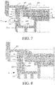
FIG. 7 is a sectional view in a B-B direction inFIG. 3 ; and -
FIG. 8 andFIG. 9 are sectional views in a C-C direction inFIG. 3 . - As shown in
FIG. 1 , arefrigeration appliance 100 includes amain body 108. Themain body 108 may be provided with astorage compartment 101 having a front opening 10. Thestorage compartment 101 may be selectively opened or closed by adoor 102. - The
storage compartment 101 includes atop wall 103, a pair of side walls (not marked), and a rear wall (not shown). The rear wall of thestorage compartment 101 faces thefront opening 10. At least some of these inner walls may be defined by aliner 109 of themain body 108. - The
refrigeration appliance 100 includes alighting module 1 configured to illuminate thestorage compartment 101. Thelighting module 1 is reachable through thestorage compartment 101. - As shown in
FIG. 1 and FIG. 2 , therefrigeration appliance 100 includes amounting slot 110 for mounting thelighting module 1. In an implementation, themounting slot 110 may be formed by a mounting shell mounted along a through hole of theliner 109 and joined to a thermal insulation material in themain body 108. In the embodiment shown inFIG. 1 , themounting slot 110 is formed by theliner 109 denting in a direction away from thestorage compartment 101. - The
lighting module 1 includes ahousing 2. Thehousing 2 is provided with afirst connection structure 21 for connecting to themounting slot 110, to detachably fasten thelighting module 1 on abox body 102. As shown inFIG. 2 , thefirst connection structure 21 may be provided with a plurality ofhooks hooks slot 111 in themounting slot 110 to fasten thelighting module 1 on themain body 108. - In an exemplary embodiment, the
lighting module 1 may be disposed on thetop wall 103. It may be easily understood that, in another embodiment, thelighting module 1 may be alternatively disposed on the side wall or the rear wall of thestorage compartment 101. - The
housing 2 is provided with alight outlet 221. Light enters thestorage compartment 101 through thelight outlet 221. As shown inFIG. 1 , thelight outlet 221 may be substantially horizontally disposed at the top of thestorage compartment 101, and thelight outlet 221 is located at the bottom of thehousing 2. Thehousing 2 may include afront wall 25 facing thefront opening 10. - When mounted on the
top wall 103 of thestorage compartment 101, thefront wall 25 is inclined from top to bottom, and has a lower part closer to the rear than an upper part. This makes a front surface of thefront wall 25 more easily visible to a user under thetop wall 103. - In an embodiment, the
front wall 25 includes amain part 251 and adecorative strip 252 fastened on a front side of themain part 251. - The
decorative strip 252 may be bonded to themain part 251 by anadhesion apparatus 258. Thedecorative strip 252 may be made of metal or a plastic base material provided with a metallic decorative layer thereon. - An upper end of the
decorative strip 252 extends into the mountingslot 110. The mountingslot 110 may be constructed with a step form at a position near the entrance and is therefore provided with a relatively shallowconcave portion 112. The upper end of thedecorative strip 252 extends into theconcave portion 112. - The
front hook 211 of thefirst connection structure 21 may be connected to theslot 111 above and behind thedecorative strip 252. In an embodiment, during mounting of thelighting module 1, a rear end of thelighting module 1 may be placed in the mountingslot 110 first, to cause therear hook 212 of thefirst connection structure 21 to abut against a rear slot in the mountingslot 110 to form a pivot. Then, thelighting module 1 is rotated around the pivot, to press thefront hook 211 into the mountingslot 110 to connect to theslot 111 in a snap-fit manner, so as to complete mounting of thelighting module 1. As thefront hook 211 of thefirst connection structure 21 is connected to theslot 111 above and behind thedecorative strip 252, and the upper end of thedecorative strip 252 is located in the relatively shallowconcave portion 112, a possibility that thedecorative strip 252 severely interferes with theliner 109 and causes the liner to fall off during the mounting of thelighting module 1 is significantly reduced. - The
main part 251 of thefront wall 25 may be provided with a pit 2510 for accommodating thedecorative strip 252, and thedecorative strip 252 is located in the pit 2510. A connectingseam 253 exposed to the front surface of thefront wall 25 is provided between upper ends of themain part 251 and thedecorative strip 252. In an exemplary embodiment, the connectingseam 253 is completely located in the mountingslot 110, and is completely covered by a front inner wall surface of the mountingslot 110 in a longitudinal direction X of thestorage compartment 101. - As shown in
FIG. 2 , the connectingseam 253 is completely located in the mountingslot 110, and is completely covered by a front inner wall surface of the mountingslot 110 in a longitudinal direction X of thestorage compartment 101. Therefore, there may be a better visual transition between a front side of thelighting module 1 and theliner 109. - The
decorative strip 252 may include anupper end portion 255 located at an upper end, alower end portion 254 located at a lower end, and adecorative portion 256 located between theupper end portion 255 and thelower end portion 254. A front surface of thedecorative portion 256 is a bevel sloping from top to bottom. At least the front surface of thedecorative portion 256 is mostly visible to a user. - An angle is formed between the
upper end portion 255 and thedecorative portion 256. A front surface of theupper end portion 255 may extend in a vertical direction and/or may be parallel to the front inner wall surface of the mountingslot 110. Anintersection ridge 259 between theupper end portion 255 and thedecorative portion 256 may be located above anedge part 1091, surrounding the mountingslot 110, of theliner 109. This helps to obtain simple design. - The
lower end portion 254 is connected to a lower end of thedecorative portion 256. Thelower end portion 254 bends from thedecorative portion 256 and extends backward, so that a connecting seam between thelower end portion 254 and themain part 251 is completely located behind a rear surface of thedecorative portion 256 in the longitudinal direction X of thestorage compartment 101. At least a part of a lower surface of thefront wall 25 is formed by thelower end portion 254. This helps to improve a decorative effect. - A rear side of the
decorative strip 252 may be provided with apositioning portion 257 protruding toward themain part 251. Themain part 251 is provided with a corresponding recess (not marked). Thepositioning portion 257 is located in the recess to position thedecorative strip 252. - The following describes the specific structure of the
lighting module 1 according to an embodiment of the present utility model in detail with reference to the accompanying drawings. - Referring to
FIG. 3 and FIG. 4 , thehousing 2 may include aframe 22 and acover 23. Alight source 3 of thelighting module 1 is located in anaccommodating space 26 defined by theframe 22 and thecover 23. - The
frame 22 may be made of opaque plastic. Theframe 22 is provided with alight outlet 221 in a wall exposed to thestorage compartment 101. Light illuminates thestorage compartment 101 through thelight outlet 221. - The
lighting module 1 includes alight guide plate 4. Thelight guide plate 4 is located between thelight outlet 221 and thecover 23. Thelight guide plate 4 is adapted to guide light from thelight source 3 toward thelight outlet 221. - The
light guide plate 4 may include a plurality of lattice points. Light in thelight guide plate 4 may concentrate again at the lattice points. The lattice points may be formed through printing or by concave/convex point portions. - The
light source 3 is located in thehousing 2. Thelight source 3 may include a plurality oflight emitting elements 31 and asubstrate 32 bearing thelight emitting elements 31. Thelight emitting elements 31 may be light-emitting diodes. - The
light guide plate 4 may cover thelight outlet 221 completely and may be basically parallel to thelight outlet 221. Thelight guide plate 4 includes afirst end surface 41 facing thelight source 3 and asecond end surface 42 opposite to thefirst end surface 41. Light emitted from thelight source 3 enters thelight guide plate 4 through thefirst end surface 41. - The
lighting module 1 may further include adiffusion board 5 located between thelight guide plate 4 and thelight outlet 221, to diffuse light from thelight guide plate 4 uniformly, so that light from thelight outlet 221 is basically uniform. - The
lighting module 1 may further include a reflectinglayer 6 located between thelight guide plate 4 and thecover 23, to cause light to illuminate thediffusion board 5 in a manner as close to total reflection as possible. - The reflecting
layer 6, thelight guide plate 4, and thediffusion board 5 may be disposed adjacent to each other in sequence between thecover 23 and thelight outlet 221. - It is found that the
light guide plate 4 is likely to expand in an environment with relatively high temperature or humidity and contract in an environment with relatively low temperature or humidity. Expansion caused by temperature change is reversible while expansion caused by humidity change is not. When thelighting module 1 is mounted in storage compartments of therefrigeration appliance 100 with different temperature or humidity, thelight guide plate 4 may change in size to different degrees. As a result, lighting quality of thesame lighting module 1 varies in the different storage compartments. For example, lighting quality of the lighting module in a refrigerating compartment and lighting quality of the lighting module in a freezing compartment are different after a particular period. Lighting quality of thelighting module 1 in the same storage compartment may also be unstable when temperature in the storage compartment is set to different temperature zones. - To resolve this problem, as shown in
FIG. 5 , thelighting module 1 according to an embodiment of the present utility model may include a first elastic member 7. The first elastic member 7 may be sandwiched between thesecond end surface 42 of thelight guide plate 4 and thehousing 2 to apply a force toward thelight source 3 to thelight guide plate 4, so that regardless of a storage compartment in which thelighting module 1 is mounted or even though thelighting module 1 is mounted in a storage compartment with different temperature zones or humidity zones, thefirst end surface 41 of thelight guide plate 4 may maintain a constant position with respect to thelight source 3, thereby improving compatibility of thelighting module 1 in therefrigeration appliance 100 and/or helping to obtain stable lighting quality. - The first elastic member 7 may be fastened at the
housing 2. In an embodiment, the first elastic member 7 may be made of elastic foam and bonded to thehousing 2. - Referring to
FIG .4 andFIG. 6 , asecond connection structure 24 is disposed between thecover 23 and theframe 22 to fasten thecover 23 and theframe 22 reliably. Thesecond connection structure 24 may include a plurality ofhooks 231 arranged at one of thecover 23 and theframe 22 distanced from one another and first throughholes 241 provided at the other of thecover 23 and theframe 22 for matching the corresponding hooks 231. - The
first connection structure 21 and thesecond connection structure 24 may be arranged in a staggered manner to prevent mutual interference. - As shown in
FIG. 5, FIG. 6 , andFIG. 7 , thelight guide plate 4, thediffusion board 5, and the reflectinglayer 6 are sandwiched between thecover 23 and theframe 22. Specifically, theframe 22 may include a supportingedge 222 surrounding thelight outlet 221. An edge of thediffusion board 5 is supported on the supportingedge 222. Therefore, thelight guide plate 4 located on a rear side of thediffusion board 5 is indirectly supported by the supportingedge 222. - After the
cover 23 and theframe 22 are fastened, a distance between the cover and the frame is relatively fixed. Thelight guide plate 4 may expand or contract in a reversible or irreversible manner in different environmental conditions (such as temperature and humidity). In view of this, thelighting module 1 may include a secondelastic member 8 located between thelight guide plate 4 and thecover 23. The secondelastic member 8 is configured to apply a force toward thelight outlet 221 to thelight guide plate 4, so that thelight guide plate 4 maintains a relatively constant position with respect to thediffusion board 5 in a direction perpendicular to thelight guide plate 4. - The second
elastic member 8 and thelight guide plate 4 are clamped between thecover 23 and theframe 22, to make the secondelastic member 8 deform to apply the force toward the light outlet to thelight guide plate 4. - The second
elastic member 8 is in contact with aninner surface 236 of thecover 23 facing thelight guide plate 4. The secondelastic member 8 may be located between the reflectinglayer 6 and thecover 23. The secondelastic member 8 may be in the form of a sheet, so that thelight guide plate 4 bears the force more uniformly. The secondelastic member 8 may be made of elastic foam. - After the
cover 23 is fastened on theframe 22 by thesecond connection structure 24, the secondelastic member 8 is sandwiched between thelight guide plate 4 and thecover 23 and deformed. Therefore, even though thelight guide plate 4 expands or contracts to different degrees in different environments, the secondelastic member 8 may still adjust a position of thelight guide plate 4 with respect to thediffusion board 5 in the direction perpendicular to thelight guide plate 4. A size of the secondelastic member 8 may be designed for the secondelastic member 8 to remain deformed within a deformation range of thelight guide plate 4. - In an exemplary embodiment, the
housing 2 includes a supportingedge 222 surrounding thelight outlet 221 and aninner frame 223 surrounding the supportingedge 222. Theinner frame 223 protrudes from the supportingedge 222 in a direction away from thelight outlet 221. An outer surface of the supportingedge 222 may form a lower surface of thehousing 2 to be exposed to thestorage compartment 101. There may be a distance between theinner frame 223 and an outer circumferential surface of thehousing 2. Thelight guide plate 4 and thediffusion board 5 are supported on an inner side surface of the supportingedge 222. - A mounting
portion 224 is provided in a space defined by thefirst end surface 41, the supportingedge 222, and theinner frame 223 of thelight guide plate 4. - The
substrate 32 of thelight source 3 is mounted on the mountingportion 224, so that thelight emitting elements 31 and thefirst end surface 41 of thelight guide plate 4 are disposed facing each other. - The
substrate 32 is mounted on theframe 22 along an inner side of theinner frame 223. Thesubstrate 32 may be basically arranged perpendicular to thelight guide plate 4. - The supporting
edge 222 and theinner frame 223 may be located on theframe 22. The mountingportion 224 may include aninsertion groove 225 that is located on theframe 22 and is used for positioning thesubstrate 32. A part of an inner surface of theinsertion groove 225 may be formed by theinner frame 223 and/or the supportingedge 222. - The
housing 2 may include a pair offirst limit portions 226 located at both ends of the mountingportion 224. Each of thefirst limit portions 226 may protrude inward a particular distance from an inner surface of theinner frame 223 and then extend toward theother limit portion 226, so as to form end portions of the mountingportion 224 to limit both ends of thesubstrate 32. - The
housing 2 may further include aprotruding rib 227 located between the pair offirst limit portions 226. There is a preset distance between theprotruding rib 227 and the inner surface of theinner frame 223, so as to limit thesubstrate 32 in the middle of thesubstrate 32. - The first elastic member 7 is located between the
second end surface 42 of thelight guide plate 4 and theinner frame 223 to apply the force toward thelight source 3 to thelight guide plate 4. The first elastic member 7 may be fastened on theinner frame 223, for example, bonded to theinner frame 223. Under the action of the first elastic member 7, thefirst end surface 41 of thelight guide plate 4 may remain abutting against thefirst limit portions 226 and/or the protrudingrib 227, so as to improve the reliability of emitting light into thelight guide plate 4 by thelight emitting elements 31. - In a direction perpendicular to the
light outlet 221, a height of theinner frame 223 may be greater than a total thickness of thediffusion board 5, thelight guide plate 4, the reflectinglayer 6, and the secondelastic member 8 stacked together. In the direction perpendicular to thelight outlet 221, a height of thesubstrate 32 is also greater than the total thickness of thediffusion board 5, thelight guide plate 4, the reflectinglayer 6, and the secondelastic member 8 stacked together, and protrudes from the secondelastic member 8 in the direction away from thelight outlet 221. This facilitates smooth placement of thesubstrate 32 in the mountingportion 224 even in a narrow space. - The
cover 23 may include asecond limit portion 235 protruding from aninner surface 230 facing thelight outlet 221. Thesecond limit portion 235 and a side close to thecover 23 of thesubstrate 32 are in contact facing each other to limit thesubstrate 32. Thesubstrate 32 is sandwiched between thesecond limit portion 235 and theinner frame 223, so that the mountingportion 224 is configured to make thelight emitting elements 31 exposed to thelight guide plate 4 in a range as large as possible. In addition, thesubstrate 32 may still be firmly fastened in thehousing 2 through the limiting of thesecond limit portion 235. - The
substrate 32 may be provided with a plurality ofavoidance holes 321, so that thesecond connection structure 24 may still pass through thesubstrate 32 to connect thecover 23 and theframe 22 even though the height of thesubstrate 32 increases. - For example, at a position corresponding to the mounting
portion 224, theinner frame 223 may be provided with a plurality of first throughholes 241 distanced from one another. Thecover 23 is provided with a plurality ofhooks 231 for extending into the first throughholes 241 to be engaged with the first through holes. The avoidance holes 321 are provided corresponding to the first throughholes 241. The avoidance holes 321 may be closed holes or formed by notches at an edge of thesubstrate 32. - The
second limit portion 235 may be located betweenadjacent hooks 231 in a length direction of thesubstrate 32. As shown inFIG. 7 , in a direction perpendicular to thesubstrate 32, thesecond limit portion 235 may be located on an inner side of thehooks 231. That is, a distance between thesecond limit portion 235 and thesubstrate 32 in the direction perpendicular to thesubstrate 32 is greater than a distance between thehooks 231 and thesubstrate 32 in the direction perpendicular to thesubstrate 32. - In the foregoing embodiment, through the adaptive adjustment of the first elastic member and/or the second elastic member in the housing, even though the light guide plate expands or contracts in the refrigeration appliance, the light guide plate can still maintain a relatively constant position with respect to the light source and/or the light outlet, so that the lighting module for a refrigeration appliance is likely to keep stable lighting quality in different environments with the light source, the light guide plate, the diffusion board, and other components thereof fastened together without glue.
- In addition, the upper end of the decorative strip of the lighting module extends into the mounting slot. Therefore, the connecting seam between the upper end of the decorative strip and the housing can be cleverly concealed in the mounting slot, and there may be a simple transition between the liner and the decorative strip, which helps to provide the refrigeration appliance with better quality.
- In the embodiment, the light source, the light guide plate, the diffusion board, and other components may be stably fastened in the housing by corresponding mechanisms, and it becomes possible to undetachably combine these parts together without glue.
- Various embodiments described with reference to
FIG. 1 to FIG. 9 may be combined with each other in any given manner to achieve the advantage of the present utility model. In addition, the present utility model is not limited to the shown embodiments. Usually, apart from the shown means, other means may also be used provided that the means can achieve the same effect.
Claims (9)
- A refrigeration appliance (100), characterized by comprising:a storage compartment (101) provided with a front opening (10), the storage compartment (101) comprising a top wall (103) and a mounting slot (110) located in the top wall (103); anda lighting module (1) fastened in the mounting slot (110), the lighting module (1) comprising a front wall (25) facing the front opening (10), the front wall (25) comprising a main part (251) and a decorative strip (252) connected to the main part (251), an upper end of the decorative strip (252) extending into the mounting slot (110).
- The refrigeration appliance (100) according to claim 1, characterized in that a connecting seam (253) between an upper end portion (255) of the decorative strip (252) and the main part (251) is located in the mounting slot (110), and is covered by a front inner wall surface of the mounting slot (110) in a longitudinal direction (X) of the storage compartment (101).
- The refrigeration appliance (100) according to claim 2, characterized in that a front surface of the upper end portion (255) extends in a vertical direction and/or is parallel to the front inner wall surface of the mounting slot (110), the decorative strip (252) comprises a decorative portion (256) sloping from top to bottom, and the upper end portion (255) is connected to an upper end of the decorative portion (256).
- The refrigeration appliance (100) according to claim 3, characterized in that an intersection ridge (259) between the upper end portion (255) and the decorative portion (256) is located above an edge part (1091), surrounding the mounting slot (110), of a liner (109) of the storage compartment (101).
- The refrigeration appliance (100) according to any one of the foregoing claims, characterized in that the decorative strip (252) comprises a lower end portion (254) and a decorative portion (256), the lower end portion (254) is connected to a lower end of the decorative portion (256), and bends backward from the decorative portion (256), and a connecting seam (253) between the lower end portion (254) and the main part (251) is completely located behind a rear surface of the decorative portion (256) in a longitudinal direction (X) of the storage compartment (101).
- The refrigeration appliance (100) according to any one of the foregoing claims, characterized in that a rear side of the decorative strip (252) is provided with a positioning portion (257) protruding toward the main part (251), the main part (251) is provided with a corresponding recess, and the positioning portion is located in the recess to position the decorative strip (252).
- The refrigeration appliance (100) according to any one of the foregoing claims, characterized in that the lighting module (1) comprises a front hook (211) configured to connect to a slot (111) in the mounting slot (110) in a snap-fit manner, the front hook (211) is connected to the slot (110) at a position above and behind the decorative strip (252), the mounting slot (110) is constructed with a step form at a position near the entrance and is therefore provided with a concave portion (112), and the decorative strip (252) extends into the concave portion (112).
- The refrigeration appliance (100) according to any one of the foregoing claims, characterized in that the lighting module (1) comprises a housing (2), the housing (2) comprises a frame (22) provided with a light outlet (221) and a cover (23) connected to the frame (22), the frame (22) or the cover (23) is provided with a snap-fit connection structure (21) connected to the mounting slot (110) in a snap-fit manner, and the decorative strip (252) is connected to the frame (22).
- The refrigeration appliance (100) according to any one of the foregoing claims, characterized in that the decorative strip (252) is made of metal or a plastic base material provided with a metallic decorative layer thereon.
Applications Claiming Priority (1)
| Application Number | Priority Date | Filing Date | Title |
|---|---|---|---|
| CN202022365121.XU CN214537056U (en) | 2020-10-21 | 2020-10-21 | Refrigeration device with lighting module |
Publications (1)
| Publication Number | Publication Date |
|---|---|
| EP3988877A1 true EP3988877A1 (en) | 2022-04-27 |
Family
ID=78087031
Family Applications (1)
| Application Number | Title | Priority Date | Filing Date |
|---|---|---|---|
| EP21201641.4A Pending EP3988877A1 (en) | 2020-10-21 | 2021-10-08 | Refrigeration appliance with lighting module |
Country Status (3)
| Country | Link |
|---|---|
| US (1) | US11566785B2 (en) |
| EP (1) | EP3988877A1 (en) |
| CN (1) | CN214537056U (en) |
Families Citing this family (2)
| Publication number | Priority date | Publication date | Assignee | Title |
|---|---|---|---|---|
| EP4332477B1 (en) * | 2021-09-10 | 2026-04-01 | Samsung Electronics Co., Ltd. | Refrigerator |
| CN219693638U (en) * | 2023-03-08 | 2023-09-15 | 博西华电器(江苏)有限公司 | Refrigerating appliance |
Citations (6)
| Publication number | Priority date | Publication date | Assignee | Title |
|---|---|---|---|---|
| US5768898A (en) * | 1995-09-18 | 1998-06-23 | Samsung Electronics Co., Ltd. | Refrigerator having fluorescent lamp for illuminating fresh food compartment |
| US20130027906A1 (en) * | 2010-03-03 | 2013-01-31 | Panasonic Corporation | Refrigerator |
| CN203744649U (en) * | 2013-02-18 | 2014-07-30 | 三菱电机株式会社 | Refrigerator and lighting device |
| WO2017198058A1 (en) * | 2016-05-20 | 2017-11-23 | 湖北美的电冰箱有限公司 | Lamp casing structure in coolbox liner and refrigeration appliance provided with same |
| CN206739706U (en) * | 2017-03-08 | 2017-12-12 | 佛山市小鲜互联电器科技有限公司 | It is a kind of that there is the fresh-keeping and refrigerator cold-storage component of illumination functions |
| CN107525036A (en) * | 2017-08-03 | 2017-12-29 | 海信容声(广东)冰箱有限公司 | The lamp case assembly and refrigerator of a kind of illuminating lamp |
-
2020
- 2020-10-21 CN CN202022365121.XU patent/CN214537056U/en active Active
-
2021
- 2021-10-08 EP EP21201641.4A patent/EP3988877A1/en active Pending
- 2021-10-21 US US17/451,679 patent/US11566785B2/en active Active
Patent Citations (6)
| Publication number | Priority date | Publication date | Assignee | Title |
|---|---|---|---|---|
| US5768898A (en) * | 1995-09-18 | 1998-06-23 | Samsung Electronics Co., Ltd. | Refrigerator having fluorescent lamp for illuminating fresh food compartment |
| US20130027906A1 (en) * | 2010-03-03 | 2013-01-31 | Panasonic Corporation | Refrigerator |
| CN203744649U (en) * | 2013-02-18 | 2014-07-30 | 三菱电机株式会社 | Refrigerator and lighting device |
| WO2017198058A1 (en) * | 2016-05-20 | 2017-11-23 | 湖北美的电冰箱有限公司 | Lamp casing structure in coolbox liner and refrigeration appliance provided with same |
| CN206739706U (en) * | 2017-03-08 | 2017-12-12 | 佛山市小鲜互联电器科技有限公司 | It is a kind of that there is the fresh-keeping and refrigerator cold-storage component of illumination functions |
| CN107525036A (en) * | 2017-08-03 | 2017-12-29 | 海信容声(广东)冰箱有限公司 | The lamp case assembly and refrigerator of a kind of illuminating lamp |
Also Published As
| Publication number | Publication date |
|---|---|
| US11566785B2 (en) | 2023-01-31 |
| CN214537056U (en) | 2021-10-29 |
| US20220120431A1 (en) | 2022-04-21 |
Similar Documents
| Publication | Publication Date | Title |
|---|---|---|
| US11566785B2 (en) | Refrigeration appliance with lighting module | |
| EP3988876A1 (en) | Lighting module and refrigeration appliance with lighting module | |
| TW201144725A (en) | Refrigerator | |
| US7147341B2 (en) | Light assembly | |
| US11525568B2 (en) | Lighting module and refrigeration appliance with lighting module | |
| CN118463486A (en) | Refrigerator body for refrigerator, preparation method of refrigerator body and refrigerator | |
| CN222504502U (en) | Box and storage equipment | |
| CN222504503U (en) | Boxes and storage equipment | |
| CN222504501U (en) | Boxes and storage equipment | |
| JP2004124685A (en) | Frame member for mounting solar cell plate | |
| JP2021113678A (en) | refrigerator | |
| US20170363347A1 (en) | Shelf assembly for a domestic cooling appliance | |
| CN223976305U (en) | Area light source assembly and refrigerator | |
| CN222670469U (en) | Mounting structure of refrigerator-freezer control by temperature change box | |
| CN218914840U (en) | Power supply assembly, chassis structure and flat lamp | |
| JP6815180B2 (en) | Mirror cabinet | |
| CN218645833U (en) | Refrigeration device | |
| CN222964246U (en) | Frame and refrigeration equipment | |
| CN217279717U (en) | Express cabinet | |
| CN223412352U (en) | Shelf component and refrigerator | |
| JPH0526467Y2 (en) | ||
| WO2019120243A1 (en) | Plane light source assembly and refrigerator provided therewith | |
| JP2026054121A (en) | refrigerator | |
| CN121025692A (en) | Boxes and storage equipment | |
| CN118517847A (en) | Refrigeration appliances |
Legal Events
| Date | Code | Title | Description |
|---|---|---|---|
| PUAI | Public reference made under article 153(3) epc to a published international application that has entered the european phase |
Free format text: ORIGINAL CODE: 0009012 |
|
| STAA | Information on the status of an ep patent application or granted ep patent |
Free format text: STATUS: THE APPLICATION HAS BEEN PUBLISHED |
|
| AK | Designated contracting states |
Kind code of ref document: A1 Designated state(s): AL AT BE BG CH CY CZ DE DK EE ES FI FR GB GR HR HU IE IS IT LI LT LU LV MC MK MT NL NO PL PT RO RS SE SI SK SM TR |
|
| STAA | Information on the status of an ep patent application or granted ep patent |
Free format text: STATUS: REQUEST FOR EXAMINATION WAS MADE |
|
| 17P | Request for examination filed |
Effective date: 20221027 |
|
| RBV | Designated contracting states (corrected) |
Designated state(s): AL AT BE BG CH CY CZ DE DK EE ES FI FR GB GR HR HU IE IS IT LI LT LU LV MC MK MT NL NO PL PT RO RS SE SI SK SM TR |
|
| STAA | Information on the status of an ep patent application or granted ep patent |
Free format text: STATUS: EXAMINATION IS IN PROGRESS |
|
| 17Q | First examination report despatched |
Effective date: 20240607 |
|
| GRAP | Despatch of communication of intention to grant a patent |
Free format text: ORIGINAL CODE: EPIDOSNIGR1 |
|
| STAA | Information on the status of an ep patent application or granted ep patent |
Free format text: STATUS: GRANT OF PATENT IS INTENDED |
|
| RIC1 | Information provided on ipc code assigned before grant |
Ipc: F25D 27/00 20060101AFI20250829BHEP Ipc: F25D 23/06 20060101ALN20250829BHEP |
|
| INTG | Intention to grant announced |
Effective date: 20250918 |