EP3988860B1 - Vehicular air-conditioning device - Google Patents
Vehicular air-conditioning device Download PDFInfo
- Publication number
- EP3988860B1 EP3988860B1 EP19934013.4A EP19934013A EP3988860B1 EP 3988860 B1 EP3988860 B1 EP 3988860B1 EP 19934013 A EP19934013 A EP 19934013A EP 3988860 B1 EP3988860 B1 EP 3988860B1
- Authority
- EP
- European Patent Office
- Prior art keywords
- refrigerant
- cooling
- heating
- heat exchanger
- electric expansion
- Prior art date
- Legal status (The legal status is an assumption and is not a legal conclusion. Google has not performed a legal analysis and makes no representation as to the accuracy of the status listed.)
- Active
Links
Images


Classifications
-
- F—MECHANICAL ENGINEERING; LIGHTING; HEATING; WEAPONS; BLASTING
- F25—REFRIGERATION OR COOLING; COMBINED HEATING AND REFRIGERATION SYSTEMS; HEAT PUMP SYSTEMS; MANUFACTURE OR STORAGE OF ICE; LIQUEFACTION SOLIDIFICATION OF GASES
- F25B—REFRIGERATION MACHINES, PLANTS OR SYSTEMS; COMBINED HEATING AND REFRIGERATION SYSTEMS; HEAT PUMP SYSTEMS
- F25B13/00—Compression machines, plants or systems, with reversible cycle
-
- B—PERFORMING OPERATIONS; TRANSPORTING
- B60—VEHICLES IN GENERAL
- B60H—ARRANGEMENTS OF HEATING, COOLING, VENTILATING OR OTHER AIR-TREATING DEVICES SPECIALLY ADAPTED FOR PASSENGER OR GOODS SPACES OF VEHICLES
- B60H1/00—Heating, cooling or ventilating devices
- B60H1/00485—Valves for air-conditioning devices, e.g. thermostatic valves
-
- B—PERFORMING OPERATIONS; TRANSPORTING
- B60—VEHICLES IN GENERAL
- B60H—ARRANGEMENTS OF HEATING, COOLING, VENTILATING OR OTHER AIR-TREATING DEVICES SPECIALLY ADAPTED FOR PASSENGER OR GOODS SPACES OF VEHICLES
- B60H1/00—Heating, cooling or ventilating devices
- B60H1/00642—Control systems or circuits; Control members or indication devices for heating, cooling or ventilating devices
- B60H1/00814—Control systems or circuits characterised by their output, for controlling particular components of the heating, cooling or ventilating installation
- B60H1/00878—Control systems or circuits characterised by their output, for controlling particular components of the heating, cooling or ventilating installation the components being temperature regulating devices
- B60H1/00899—Controlling the flow of liquid in a heat pump system
- B60H1/00907—Controlling the flow of liquid in a heat pump system where the flow direction of the refrigerant changes and an evaporator becomes condenser
-
- B—PERFORMING OPERATIONS; TRANSPORTING
- B61—RAILWAYS
- B61D—BODY DETAILS OR KINDS OF RAILWAY VEHICLES
- B61D27/00—Heating, cooling, ventilating, or air-conditioning
- B61D27/0018—Air-conditioning means, i.e. combining at least two of the following ways of treating or supplying air, namely heating, cooling or ventilating
-
- F—MECHANICAL ENGINEERING; LIGHTING; HEATING; WEAPONS; BLASTING
- F25—REFRIGERATION OR COOLING; COMBINED HEATING AND REFRIGERATION SYSTEMS; HEAT PUMP SYSTEMS; MANUFACTURE OR STORAGE OF ICE; LIQUEFACTION SOLIDIFICATION OF GASES
- F25B—REFRIGERATION MACHINES, PLANTS OR SYSTEMS; COMBINED HEATING AND REFRIGERATION SYSTEMS; HEAT PUMP SYSTEMS
- F25B49/00—Arrangement or mounting of control or safety devices
- F25B49/02—Arrangement or mounting of control or safety devices for compression type machines, plants or systems
-
- B—PERFORMING OPERATIONS; TRANSPORTING
- B60—VEHICLES IN GENERAL
- B60H—ARRANGEMENTS OF HEATING, COOLING, VENTILATING OR OTHER AIR-TREATING DEVICES SPECIALLY ADAPTED FOR PASSENGER OR GOODS SPACES OF VEHICLES
- B60H1/00—Heating, cooling or ventilating devices
- B60H1/00642—Control systems or circuits; Control members or indication devices for heating, cooling or ventilating devices
- B60H1/00814—Control systems or circuits characterised by their output, for controlling particular components of the heating, cooling or ventilating installation
- B60H1/00878—Control systems or circuits characterised by their output, for controlling particular components of the heating, cooling or ventilating installation the components being temperature regulating devices
- B60H2001/00935—Control systems or circuits characterised by their output, for controlling particular components of the heating, cooling or ventilating installation the components being temperature regulating devices comprising four way valves for controlling the fluid direction
-
- F—MECHANICAL ENGINEERING; LIGHTING; HEATING; WEAPONS; BLASTING
- F25—REFRIGERATION OR COOLING; COMBINED HEATING AND REFRIGERATION SYSTEMS; HEAT PUMP SYSTEMS; MANUFACTURE OR STORAGE OF ICE; LIQUEFACTION SOLIDIFICATION OF GASES
- F25B—REFRIGERATION MACHINES, PLANTS OR SYSTEMS; COMBINED HEATING AND REFRIGERATION SYSTEMS; HEAT PUMP SYSTEMS
- F25B2313/00—Compression machines, plants or systems with reversible cycle not otherwise provided for
- F25B2313/029—Control issues
- F25B2313/0292—Control issues related to reversing valves
-
- F—MECHANICAL ENGINEERING; LIGHTING; HEATING; WEAPONS; BLASTING
- F25—REFRIGERATION OR COOLING; COMBINED HEATING AND REFRIGERATION SYSTEMS; HEAT PUMP SYSTEMS; MANUFACTURE OR STORAGE OF ICE; LIQUEFACTION SOLIDIFICATION OF GASES
- F25B—REFRIGERATION MACHINES, PLANTS OR SYSTEMS; COMBINED HEATING AND REFRIGERATION SYSTEMS; HEAT PUMP SYSTEMS
- F25B2600/00—Control issues
- F25B2600/25—Control of valves
- F25B2600/2513—Expansion valves
Definitions
- the present invention relates to a vehicular air-conditioning device.
- WO 2017/212631 describes a known air-conditioning device that is switchable between a cooling state for cooling and a heating state for heating by switching the direction of refrigerant circulation in a refrigeration cycle.
- This air-conditioning device includes a single electronic expansion valve used both in the cooling and heating states.
- refrigerant pass direction the direction in which the refrigerant passes through the electronic expansion valve
- JPH10-26429 describes a known air-conditioning device that includes different electronic expansion valves in the cooling and heating states.
- This air-conditioning device includes a cooling electronic expansion valve that expands the refrigerant in the cooling state and a heating electronic expansion valve that expands the refrigerant in the heating state. The refrigerant flows unidirectionally through each of the cooling and heating electronic expansion valves.
- a vehicular air-conditioning device mounted on a vehicle may use carbon dioxide as a nonflammable refrigerant.
- Carbon dioxide has relatively high saturation pressure.
- carbon dioxide used as a refrigerant has a large difference in pressure between upstream and downstream from an electronic expansion valve.
- the structure in WO 2017/212631 is likely to fail to control the performance of air-conditioning the vehicle interior (hereafter, air-conditioning performance). This is because the dynamic characteristics of the electronic expansion valve may change depending on a direction in which a refrigerant passes through the electronic expansion valve particularly when the refrigerant has a large difference in pressure between upstream and downstream from an electronic expansion valve.
- the refrigerant flows unidirectionally through each of the cooling and heating electronic expansion valves.
- a bypass line including a check valve is to be included for each of the cooling and heating electronic expansion valves.
- a bypass line is to be included for the cooling electronic expansion valve for the refrigerant to bypass the cooling electronic expansion valve during heating.
- a bypass line is to be included for the heating electronic expansion valve for the refrigerant to bypass the heating electronic expansion valve during cooling.
- US2003037562 A1 discloses a vehicle air conditioner for heating a passenger compartment by a heater core and a heat pump cycle, wherein when operation of a heat pump cycle is switched from a defrosting operation to a heating assist operation, a heating degree of the heater core is increased higher than a predetermined heating degree. Further, when the operation of the heat pump cycle is switched from the defrosting operation to the heating assist operation, an air outlet mode except for a defrosting mode for defrosting a windshield is set. Further, in the defrosting operation of the heat pump cycle, the temperature of an interior heat exchanger of the heat pump cycle is set higher.
- An objective of the present disclosure is to provide a vehicular air-conditioning device that has a simple structure and can facilitate the air-conditioning performance control using a refrigerant containing carbon dioxide.
- a vehicular air-conditioning device according to an aspect of the present invention according to claim 1 includes:
- the above structure prevents a refrigerant from flowing into a cooling electric expansion device in a heating state, and prevents the refrigerant from flowing into a heating electric expansion device in a cooling state.
- the refrigerant unidirectionally passes through each of the cooling and heating electric expansion devices.
- This structure does not change dynamic characteristics of the cooling and heating electric expansion devices depending on the directions in which the refrigerant passes. This structure thus facilitates air-conditioning performance control regardless of using a refrigerant containing carbon dioxide having a high saturation pressure.
- the cooling and heating electric expansion devices are connected in parallel.
- the cooling electric expansion device serves as a bypass for the refrigerant to bypass the heating electric expansion device.
- the heating electric expansion device serves as a bypass for the refrigerant to bypass the cooling electric expansion device.
- a railway-vehicle air-conditioning device according to one or more embodiments is described with reference to the drawings using a railway vehicle as an example.
- the same or corresponding components are given the same reference numerals.
- a railway-vehicle air-conditioning device 200 includes a refrigeration cycle 100 in which a refrigerant circulates.
- the refrigeration cycle 100 generates cooling to cool a non-illustrated passenger compartment in a railway vehicle, and generates heat to heat the passenger compartment.
- An example refrigerant contains carbon dioxide as a main component, or more specifically, carbon dioxide with a purity of 99.9% or greater with refrigerant number R744.
- carbon dioxide is particularly suitable for the refrigeration cycle 100 mounted on a railway vehicle.
- carbon dioxide has a low global warming potential.
- the refrigeration cycle 100 includes a compressor 110 that compresses the refrigerant, an expander 120 that expands the refrigerant, and an outdoor heat exchanger 130 and an indoor heat exchanger 140 that form the refrigeration cycle 100 together with the compressor 110 and the expander 120.
- One of the outdoor heat exchanger 130 or the indoor heat exchanger 140 functions as a condenser that condenses the refrigerant, and the other functions as an evaporator that evaporates the refrigerant.
- the railway-vehicle air-conditioning device 200 includes an outdoor fan 210 that forms an airflow blowing against the outdoor heat exchanger 130.
- the airflow formed by the outdoor fan 210 facilitates heat exchange between the outdoor heat exchanger 130 and outside air or air out of a non-illustrated railway vehicle.
- the railway-vehicle air-conditioning device 200 also includes an indoor fan 220 that forms an airflow blowing against the indoor heat exchanger 140.
- the airflow formed by the indoor fan 220 facilitates heat exchange between the indoor heat exchanger 140 and inside air or air inside the non-illustrated passenger compartment.
- the railway-vehicle air-conditioning device 200 also includes a four-way valve 230 serving as a switching device that switches the direction of refrigerant circulation in the refrigeration cycle 100.
- the four-way valve 230 switches a state of the refrigeration cycle 100 between a cooling state in which the outdoor heat exchanger 130 operates as a condenser and the indoor heat exchanger 140 operates as an evaporator and a heating state in which the indoor heat exchanger 140 operates as a condenser and the outdoor heat exchanger 130 operates as an evaporator.
- the railway-vehicle air-conditioning device 200 also includes a controller 240 that controls the rotational speed of the compressor 110, the expansion degree at which the expander 120 expands the refrigerant, the rotational speed of the outdoor fan 210, the rotational speed of the indoor fan 220, and the four-way valve 230. Under the control of the controller 240, the four-way valve 230 switches the state between the cooling and heating states.
- the refrigerant circulates in the compressor 110, the outdoor heat exchanger 130, the expander 120, and the indoor heat exchanger 140 in this order.
- a refrigerant flow (hereafter referred to as cooling refrigerant flow) FC flowing from the outdoor heat exchanger 130 toward the indoor heat exchanger 140 is formed between the outdoor heat exchanger 130 and the indoor heat exchanger 140.
- the refrigerant circulates in the compressor 110, the indoor heat exchanger 140, the expander 120, and the outdoor heat exchanger 130 in this order.
- a refrigerant flow (hereafter, heating refrigerant flow) FW flowing from the indoor heat exchanger 140 toward the outdoor heat exchanger 130 is formed between the outdoor heat exchanger 130 and the indoor heat exchanger 140.
- heating refrigerant flow FW flowing from the indoor heat exchanger 140 toward the outdoor heat exchanger 130
- the direction in which the refrigerant passes through the expander 120 changes between the cooling and heating states.
- the structure according to the present embodiment particularly includes the expander 120 adaptive to a change of the direction in which the refrigerant passes.
- the structure of the expander 120 is described more specifically below.
- the expander 120 includes electronic expansion valves.
- the electronic expansion valves herein refer to elements that expand the refrigerant by reducing refrigerant flows that pass through the valves and allows regulation of the degree of the refrigerant flow reduction with an external electronic control.
- the electronic expansion valves include an electronic linear expansion valve.
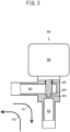
- FIG. 3 shows an example structure of the electronic expansion valves included in the expander 120.
- an electronic expansion valve 60 includes a first port 61 defining a hollow tubular flow path, a second port 62 defining a hollow tubular flow path extending in a direction intersecting with the first port 61, and a funnel-shaped valve seat 63 that connects the first port 61 and the second port 62 at an intersection of the first port 61 and the second port 62.
- the electronic expansion valve 60 also includes a valve rod 65 including a needle valve 64 shaped to fit to the valve seat 63 at the tip, and a forward-rearward movement mechanism 66 that moves the valve rod 65 forward and rearward to change the size of the clearance between the needle valve 64 and the valve seat 63.
- the forward-rearward movement mechanism 66 moves the valve rod 65 forward and rearward upon receiving an electronic control from the controller 240 illustrated in FIG. 1 .
- the electronic expansion valve 60 allows the refrigerant to pass through in a direction from one of the first port 61 or the second port 62 to the other.
- the refrigerant flow is reduced in the clearance between the needle valve 64 and the valve seat 63 to expand the refrigerant with valve expansion.
- Changing the clearance between the needle valve 64 and the valve seat 63 can adjust the degree at which the refrigerant expands (hereafter, expansion degree).
- Passage of the refrigerant from the first port 61 toward the second port 62 is referred to as forward passage P1
- passage of the refrigerant from the second port 62 toward the first port 61 is referred to as reverse passage P2.
- a force used to reduce the refrigerant flow differs between the forward passage P1 and the reverse passage P2. More specifically, the valve rod 65 traverses the first port 61 and extends in parallel to the second port 62. Thus, a force used to reduce the refrigerant flow, that is, a force used to move the valve rod 65 forward is larger for the reverse passage P2 than for the forward passage P1.
- the electronic expansion valve 60 in the present embodiment changes the force used to reduce the refrigerant flow depending on the direction in which the refrigerant passes.
- the dynamic characteristics of opening or closing the electronic expansion valve 60, or more specifically, the dynamic characteristics of moving the valve rod 65 forward or rearward change depending on the direction in which the refrigerant passes.
- carbon dioxide serving as a refrigerant has a large pressure difference at the front and rear of the electronic expansion valve 60.
- the dynamic characteristics of moving the valve rod 65 forward and rearward largely change depending on the direction in which the refrigerant passes.
- the structure according to the present embodiment avoids a failure in air-conditioning performance control regardless of using the electronic expansion valve 60 having the dynamic characteristics changeable depending on the direction in which the refrigerant passes. This is described in detail with reference to FIG. 2 .
- the expander 120 includes a cooling electronic expansion valve 11 including the electronic expansion valve 60 illustrated in FIG. 3 , and a heating electronic expansion valve 21 including the electronic expansion valve 60 illustrated in FIG. 3 .
- the heating electronic expansion valve 21 is connected in parallel to the cooling electronic expansion valve 11 to form parallel flows of the refrigerant.
- the expander 120 also includes a heating check valve 31 connected in series to the cooling electronic expansion valve 11 to form a series flow of the refrigerant, and a cooling check valve 41 connected in series to the heating electronic expansion valve 21 to form a series flow of the refrigerant.
- the cooling electronic expansion valve 11 and the heating check valve 31 connected in series and the heating electronic expansion valve 21 and the cooling check valve 41 connected in series are connected in parallel to each other.
- the heating check valve 31 blocks the heating refrigerant flow FW from flowing into the cooling electronic expansion valve 11.
- the heating check valve 31 is located to block passage of the heating refrigerant flow FW and allow passage of the cooling refrigerant flow FC.
- the cooling check valve 41 blocks the cooling refrigerant flow FC from flowing into the heating electronic expansion valve 21.
- the cooling check valve 41 is located to block passage of the cooling refrigerant flow FC and allow passage of the heating refrigerant flow FW.
- the heating check valve 31 and the cooling check valve 41 form a blocking device 50 that blocks the refrigerant from flowing into the cooling electronic expansion valve 11 in the heating state, and from flowing into the heating electronic expansion valve 21 in the cooling state.
- the cooling and heating electronic expansion valves 11 and 21 are used separately in the cooling and heating states. More specifically, in the cooling state, the cooling electronic expansion valve 11 functions as a cooling electric expansion device 10 that expands the refrigerant condensed by the outdoor heat exchanger 130 illustrated in FIG. 1 . In the heating state, the heating electronic expansion valve 21 functions as the heating electric expansion device 20 that expands the refrigerant condensed by the indoor heat exchanger 140 illustrated in FIG. 1 .
- the refrigerant unidirectionally flows through each of the cooling and heating electronic expansion valves 11 and 21. More specifically, the cooling refrigerant flow FC flows through the cooling electronic expansion valve 11 alone, and the heating refrigerant flow FW flows through the heating electronic expansion valve 21 alone.
- This structure does not change the dynamic characteristics of the cooling and heating electronic expansion valves 11 and 21 depending on the direction in which the refrigerant passes. This structure thus facilitates air-conditioning performance control regardless of using carbon dioxide with a high saturation pressure as a refrigerant.
- the cooling electronic expansion valve 11 is located to allow the cooling refrigerant flow FC corresponding to the forward passage P1 illustrated in FIG. 3 .
- the heating electronic expansion valve 21 is located to allow the heating refrigerant flow FW corresponding to the forward passage P1 illustrated in FIG. 3 .
- each of the cooling and heating electronic expansion valves 11 and 21 uses a small force to reduce the refrigerant flow.
- each of the cooling and heating electronic expansion valves 11 and 21 can easily improve the resolution for adjusting the expansion degree of the refrigerant.
- Carbon dioxide with a high saturation pressure is used as a refrigerant.
- the expansion degree of the refrigerant can be easily controlled precisely regardless of with a large difference between the pressures across the cooling electronic expansion valve 11 in the cooling state and a large difference between the pressures across the heating electronic expansion valve 21 in the heating state.
- the cooling and heating electronic expansion valves 11 and 21 are connected in parallel to each other.
- the cooling electronic expansion valve 11 and the heating check valve 31 function as a bypass for the refrigerant to bypass the heating electronic expansion valve 21.
- the heating electronic expansion valve 21 and the cooling check valve 41 function as a bypass for the refrigerant to bypass the cooling electronic expansion valve 11.
- This structure can eliminate dedicated bypass lines for the cooling and heating electronic expansion valves 11 and 21, and can thus be simplified.
- the cooling and heating electronic expansion valves 11 and 21 are used separately, and thus the frequency of use of the cooling and heating electronic expansion valves 11 and 21 can be reduced.
- This structure can thus further reduce the failure rate, compared with structures with a common electronic expansion valve used both in the cooling state and the heating state and with the refrigerant flow through the electronic expansion valve and rectified with a bridge circuit.
- the cooling electric expansion device 10 that expands the refrigerant in the cooling state includes a single cooling electronic expansion valve 11.
- the heating electric expansion device 20 that expands the refrigerant in the heating state includes a single heating electronic expansion valve 21.
- the cooling and heating electric expansion devices 10 and 20 may each include more than one electronic expansion valve 60.
- a specific example in which the cooling electric expansion device 10 includes more electronic expansion valves 60 than the heating electric expansion device 20 is described.
- the expander 120 includes a first cooling electronic expansion valve 12 and a second cooling electronic expansion valve 13 connected in parallel to each other, a first heating check valve 32 connected in series to the first cooling electronic expansion valve 12, and a second heating check valve 33 connected in series to the second cooling electronic expansion valve 13.
- the cooling electric expansion device 10 that expands the refrigerant in the cooling state includes two electronic expansion valves 60 serving as the first cooling electronic expansion valve 12 and the second cooling electronic expansion valve 13.
- the present embodiment is the same as Embodiment 1 in that, in the heating state, the heating electric expansion device 20 that expands the refrigerant includes a single heating electronic expansion valve 21, and that a single cooling check valve 41 is directly connected to the heating electronic expansion valve 21.
- the first cooling electronic expansion valve 12 and the first heating check valve 32 connected in series and the second cooling electronic expansion valve 13 and the second heating check valve 33 connected in series are connected in parallel, and the heating electronic expansion valve 21 and the cooling check valve 41 connected in series are connected in parallel to the valves 12 and 32 and the valves 13 and 33.
- the first heating check valve 32 blocks the heating refrigerant flow FW from flowing into the first cooling electronic expansion valve 12 in the heating state, and allows the cooling refrigerant flow FC to flow into the first cooling electronic expansion valve 12 in the cooling state.
- the second heating check valve 33 blocks the heating refrigerant flow FW from flowing into the second cooling electronic expansion valve 13 in the heating state, and allows the cooling refrigerant flow FC to flow into the second cooling electronic expansion valve 13 in the cooling state.
- the first heating check valve 32, the second heating check valve 33, and the cooling check valve 41 form the blocking device 50 that enables separate uses of the cooling and heating electric expansion devices 10 and 20.
- the refrigerant is expanded with a single heating electronic expansion valve 21 in the heating state, and the refrigerant is expanded with the two electronic expansion valves 60 serving as the first cooling electronic expansion valve 12 and the second cooling electronic expansion valve 13 in the cooling state.
- This structure can thus improve the capability of the expander 120 expanding the refrigerant in the cooling state further than the capability of the expander 120 expanding the refrigerant in the heating state.
- This structure can thus appropriately expand the refrigerant in the cooling state when the circulation rate of the refrigerant per unit time in the refrigeration cycle 100 illustrated in FIG. 1 is to be increased further than in the heating state.
- All of the first cooling electronic expansion valve 12, the second cooling electronic expansion valve 13, and the heating electronic expansion valve 21 are the electronic expansion valves 60 illustrated in FIG. 3 . Such common components can reduce the costs.
- FIG. 2 shows a structure in which the heating check valve 31 is located upstream from the cooling electronic expansion valve 11 in the direction of the cooling refrigerant flow FC, and the cooling check valve 41 is located upstream from the heating electronic expansion valve 21 in the direction of the heating refrigerant flow FW.
- the heating check valve 31 may be located at any position to be connected in series to the cooling electronic expansion valve 11.
- the cooling check valve 41 may be located at any position to be connected in series to the heating electronic expansion valve 21. A specific example in which the positions of the heating check valve 31 and the cooling check valve 41 are changed is described below.
- the heating check valve 31 is located downstream from the cooling electronic expansion valve 11 in the direction of the cooling refrigerant flow FC.
- the cooling check valve 41 is located downstream from the heating electronic expansion valve 21 in the direction of the heating refrigerant flow FW.
- the present embodiment can produce the same effects as in Embodiment 1.
- FIG. 4 shows an example structure in which the blocking device 50 that enables separate uses of the cooling and heating electric expansion devices 10 and 20 includes the first heating check valve 32, the second heating check valve 33, and the cooling check valve 41.
- the blocking device 50 may include components other than check valves. A specific example structure is described.
- the blocking device 50 that enables separate uses of the cooling and heating electric expansion devices 10 and 20 includes a three-way valve 51.
- the three-way valve 51 connects the first cooling electronic expansion valve 12 and the second cooling electronic expansion valve 13 serving as the cooling electric expansion device 10 to the outdoor heat exchanger 130 and the indoor heat exchanger 140 illustrated in FIG. 1 , and disconnects the heating electronic expansion valve 21 serving as the heating electric expansion device 20 from the outdoor heat exchanger 130 or the indoor heat exchanger 140 illustrated in FIG. 1 .
- the three-way valve 51 connects the heating electronic expansion valve 21 serving as the heating electric expansion device 20 to the outdoor heat exchanger 130 and the indoor heat exchanger 140 illustrated in FIG. 1 , and disconnects the first cooling electronic expansion valve 12 and the second cooling electronic expansion valve 13 serving as the cooling electric expansion device 10 from the outdoor heat exchanger 130 or the indoor heat exchanger 140 illustrated in FIG. 1 .
- the blocking device 50 that enables separate uses of the cooling and heating electric expansion devices 10 and 20 can include a single three-way valve 51.
- the structure according to the present embodiment can thus reduce the number of components further than in Embodiments 1 and 2. Other effects are the same as in Embodiment 2.
- FIG. 1 shows an example structure in which the four-way valve 230 serves as a switching device that switches the direction of refrigerant circulation in the refrigeration cycle 100.
- the switching device may include a component other than the four-way valve 230. A specific example structure is described.
- the compressor 110 includes an inlet IN through which the refrigerant evaporated by the evaporator flows in and an outlet OUT through which the refrigerant after being compressed flows out toward the condenser.
- a switching circuit 231 connects the outlet OUT of the compressor 110, the inlet IN of the compressor 110, the outdoor heat exchanger 130, and the indoor heat exchanger 140 to each other.
- the switching circuit 231 includes a first electromagnetic valve 231a, a second electromagnetic valve 231b, a third electromagnetic valve 231c, and a fourth electromagnetic valve 231d that are switchable between an open state in which the refrigerant is allowed to pass through, and a closed state in which the refrigerant is blocked from passing through.
- the first electromagnetic valve 231a is located in the refrigerant flow path between the outlet OUT of the compressor and the outdoor heat exchanger 130.
- the second electromagnetic valve 231b is located in the refrigerant flow path between the outlet OUT of the compressor and the indoor heat exchanger 140.
- the third electromagnetic valve 231c is located in the refrigerant flow path between the inlet IN of the compressor and the indoor heat exchanger 140.
- the fourth electromagnetic valve 231d is located in the refrigerant flow path between the inlet IN of the compressor and the outdoor heat exchanger 130.
- the first electromagnetic valve 231a and the third electromagnetic valve 231c are open, whereas the second electromagnetic valve 231b and the fourth electromagnetic valve 231d are closed.
- This structure forms the cooling refrigerant flow FC flowing from the outlet OUT of the compressor toward the outdoor heat exchanger 130 serving as a condenser, and the cooling refrigerant flow FC returning from the indoor heat exchanger 140 serving as an evaporator to the inlet IN of the compressor.
- the second electromagnetic valve 231b and the fourth electromagnetic valve 231d are open, whereas the first electromagnetic valve 231a and the third electromagnetic valve 231c are closed.
- This structure forms the heating refrigerant flow FW flowing from the outlet OUT of the compressor toward the indoor heat exchanger 140 serving as a condenser, and the heating refrigerant flow FW returning from the outdoor heat exchanger 130 serving as an evaporator to the inlet IN of the compressor.
- the switching circuit 231 serves as a switching device that switches the direction of refrigerant circulation in the refrigeration cycle 100 illustrated in FIG. 1 .
- the present embodiment can also produce the same effects as in Embodiment 1.
- the controller 240 illustrated in FIG. 1 can control the expander. With the control, the degree at which the refrigerant flow is reduced in the cooling state by the cooling electric expansion device 10 is pre-controlled before a shift from the heating state to the cooling state, and the degree at which the refrigerant flow is reduced in the heating state by the heating electric expansion device 20 is pre-controlled before a shift from the cooling state to the heating state.
- the control is described in detail below.
- the controller 240 determines whether the refrigeration cycle 100 currently operates in the cooling state or in the heating state (step S1).
- the controller 240 acquires, from a non-illustrated sensor, detection results including the rotational speed of the compressor 110, and the temperature and the pressure of the refrigerant that flows into the compressor 110 (step S2).
- the controller 240 controls the degree at which the cooling electric expansion device 10 reduces the refrigerant flow, or more specifically, controls the position of the valve rod 65 in the electronic expansion valve 60 illustrated in FIG. 3 included in the cooling electric expansion device 10 in the forward-rearward movement direction (step S3).
- the controller 240 acquires, from a non-illustrated sensor, a detected value of the current temperature (hereafter, detected temperature) in the passenger compartment to be air-conditioned, and acquires a deviation between the detected temperature and a target value of the temperature (hereafter, target temperature) of the passenger compartment (step S4).
- the controller 240 pre-controls the degree at which the heating electric expansion device 20 reduces the refrigerant flow in the subsequent heating state, or more specifically, controls the position of the valve rod 65 in the electronic expansion valve 60 illustrated in FIG. 3 included in the heating electric expansion device 20 in the forward-rearward movement direction (step S5).
- the controller 240 acquires, from a non-illustrated sensor, detection results including the rotational speed of the compressor 110, and the temperature and the pressure of the refrigerant that flows into the compressor 110 (step S6).
- the controller 240 controls the degree at which the heating electric expansion device 20 reduces the refrigerant flow, or more specifically, controls the position of the valve rod 65 in the electronic expansion valve 60 illustrated in FIG. 3 included in the heating electric expansion device 20 in the forward-rearward movement direction (step S7).
- the controller 240 then acquires, from a non-illustrated sensor, a detected temperature in the passenger compartment, and acquires a deviation between the detected temperature and a target temperature in the passenger compartment (step S8). Based on the deviation acquired, the controller 240 pre-controls the degree at which the cooling electric expansion device 10 reduces the refrigerant flow in the subsequent cooling state, or more specifically, controls the position of the valve rod 65 in the electronic expansion valve 60 illustrated in FIG. 3 included in the cooling electric expansion device 10 in the forward-rearward movement direction (step S9).
- step S10 the controller 240 determines whether to end the operation of the compressor 110 (step S10). To continue the operation of the compressor 110 (NO in step S10), the controller 240 returns to step S1. To end the operation of the compressor 110 (YES in step S10), the controller 240 ends the expander control.
- the structure according to the present embodiment constantly controls the degree at which the heating electric expansion device 20 reduces the refrigerant flow in addition to the degree at which the cooling electric expansion device 10 reduces the refrigerant flow.
- the structure according to the present embodiment constantly controls the degree at which the cooling electric expansion device 10 reduces the refrigerant flow in addition to the degree at which the heating electric expansion device 20 reduces the refrigerant flow.
- the degree at which the expander 120 expands the refrigerant is already controlled as appropriate.
- This structure is less likely to cause an unstable air-conditioning performance when the cooling or heating state is switched to the other, and enables smooth adjustment of the passenger compartment to a comfortable thermal environment.
- each of the cooling and heating electric expansion devices 10 and 20 includes the valve rod 65 that adjusts the refrigerant flow rate, the first port 61 defining the flow path crossing the valve rod 65, and the second port 62 defining the flow path parallel to the valve rod.
- Each of the cooling and heating electric expansion devices 10 and 20 is located in the direction in which the refrigerant passes from the first port 61 to the second port 62.
- each of the cooling and heating electric expansion devices 10 and 20 is not limited to the example structure illustrated in FIG. 3 .
- each of the cooling and heating electric expansion devices 10 and 20 may include an element that uses different magnitudes of force to reduce the refrigerant flow depending on the direction in which the refrigerant passes.
- the blocking device 50 that enables separate uses of the cooling and heating electric expansion devices 10 and 20 includes the heating check valve 31 and the cooling check valve 41.
- an element included in the blocking device 50 may be other than check valves.
- the blocking device 50 may include an electromagnetic valve that is switchable between a closed state in which a refrigerant flow is blocked and an open state in which the refrigerant flow is allowed and that can adjust the refrigerant flow rate.
- the blocking device 50 according to Embodiment 2 may also be formed similarly.
- the blocking device 50 also has the function of adjusting the flow rate of the refrigerant flowing into the cooling electric expansion device 10 in the cooling state, and the function of adjusting the flow rate of the refrigerant flowing into the heating electric expansion device 20 in the heating state. This structure can thus finely control the air-conditioning performance.
- the cooling electric expansion device 10 includes more electronic expansion valves 60 than the heating electric expansion device 20. This structure can further improve the air-conditioning performance for cooling than for heating.
- the heating electric expansion device 20 may include more electronic expansion valves 60 than the cooling electric expansion device 10.
- each of the cooling and heating electric expansion devices 10 and 20 includes a single electronic expansion valve 60 or multiple electronic expansion valves 60 connected in parallel, and the number of electronic expansion valves 60 included in the cooling electric expansion device 10 differs from the number of electronic expansion valves 60 included in the heating electric expansion device 20, the air-conditioning performance can be varied between cooling and heating.
- the railway vehicle herein includes a bullet train, a monorail, and other vehicles that travels along tracks, in addition to an electric train.
- a vehicle on which the refrigeration cycle 100 is to be mounted may be a bus or other automobiles, in addition to a railway vehicle.
- the vehicular air-conditioning device is applicable to air conditioning of a passenger compartment defined in a vehicle.
Landscapes
- Engineering & Computer Science (AREA)
- Mechanical Engineering (AREA)
- Physics & Mathematics (AREA)
- Thermal Sciences (AREA)
- General Engineering & Computer Science (AREA)
- Air-Conditioning For Vehicles (AREA)
Description
- The present invention relates to a vehicular air-conditioning device.
-
WO 2017/212631 describes a known air-conditioning device that is switchable between a cooling state for cooling and a heating state for heating by switching the direction of refrigerant circulation in a refrigeration cycle. This air-conditioning device includes a single electronic expansion valve used both in the cooling and heating states. In this structure, the direction in which the refrigerant passes through the electronic expansion valve (hereafter, refrigerant pass direction) changes between the cooling and heating states. -
JPH10-26429 - For integrity, a vehicular air-conditioning device mounted on a vehicle may use carbon dioxide as a nonflammable refrigerant. Carbon dioxide has relatively high saturation pressure. Thus, carbon dioxide used as a refrigerant has a large difference in pressure between upstream and downstream from an electronic expansion valve.
- With carbon dioxide used as a refrigerant, the structure in
WO 2017/212631 is likely to fail to control the performance of air-conditioning the vehicle interior (hereafter, air-conditioning performance). This is because the dynamic characteristics of the electronic expansion valve may change depending on a direction in which a refrigerant passes through the electronic expansion valve particularly when the refrigerant has a large difference in pressure between upstream and downstream from an electronic expansion valve. - In an air-conditioning device described in
JPH10-26429 - To use the cooling and heating electronic expansion valves separately, a bypass line including a check valve is to be included for each of the cooling and heating electronic expansion valves.
- A bypass line is to be included for the cooling electronic expansion valve for the refrigerant to bypass the cooling electronic expansion valve during heating. A bypass line is to be included for the heating electronic expansion valve for the refrigerant to bypass the heating electronic expansion valve during cooling. Such multiple dedicated bypass lines complicate the structure.
-
US2003037562 A1 discloses a vehicle air conditioner for heating a passenger compartment by a heater core and a heat pump cycle, wherein when operation of a heat pump cycle is switched from a defrosting operation to a heating assist operation, a heating degree of the heater core is increased higher than a predetermined heating degree. Further, when the operation of the heat pump cycle is switched from the defrosting operation to the heating assist operation, an air outlet mode except for a defrosting mode for defrosting a windshield is set. Further, in the defrosting operation of the heat pump cycle, the temperature of an interior heat exchanger of the heat pump cycle is set higher. An objective of the present disclosure is to provide a vehicular air-conditioning device that has a simple structure and can facilitate the air-conditioning performance control using a refrigerant containing carbon dioxide. - To achieve the above objective, a vehicular air-conditioning device according to an aspect of the present invention according to
claim 1 includes: - a compressor to compress a refrigerant;
- an expander to expand the refrigerant;
- an outdoor heat exchanger and an indoor heat exchanger that form a refrigeration cycle together with the compressor and the expander, each of the outdoor heat exchanger and the indoor heat exchanger being operable in the refrigeration cycle as a condenser to condense the refrigerant and an evaporator to evaporate the refrigerant, wherein one of the outdoor heat exchanger or the indoor heat exchanger operates as the condenser when the other of the outdoor heat exchanger or the indoor heat exchanger operates as the evaporator; and
- a switching device to switch a state of the refrigeration cycle between a cooling state in which the outdoor heat exchanger operates as the condenser and the indoor heat exchanger operates as the evaporator and a heating state in which the indoor heat exchanger operates as the condenser and the outdoor heat exchanger operates as the evaporator, in which
- the refrigerant contains carbon dioxide, and
- the expander includes
- a cooling electric expansion device to expand the refrigerant condensed by the outdoor heat exchanger when the refrigeration cycle is in the cooling state,
- a heating electric expansion device connected in parallel to the cooling electric expansion device to form flows of the refrigerant that are parallel to each other and configured to expand the refrigerant condensed by the indoor heat exchanger when the refrigeration cycle is in the heating state, and
- a blocking device to block the refrigerant from flowing into the cooling electric expansion device when the refrigeration cycle is in the heating state, and to block the refrigerant from flowing into the heating electric expansion device when the refrigeration cycle is in the cooling state.
- The above structure prevents a refrigerant from flowing into a cooling electric expansion device in a heating state, and prevents the refrigerant from flowing into a heating electric expansion device in a cooling state. Thus, the refrigerant unidirectionally passes through each of the cooling and heating electric expansion devices. This structure does not change dynamic characteristics of the cooling and heating electric expansion devices depending on the directions in which the refrigerant passes. This structure thus facilitates air-conditioning performance control regardless of using a refrigerant containing carbon dioxide having a high saturation pressure.
- The cooling and heating electric expansion devices are connected in parallel. Thus, in the cooling state in which the refrigerant is prevented from flowing into the heating electric expansion device, the cooling electric expansion device serves as a bypass for the refrigerant to bypass the heating electric expansion device. In the heating state where the refrigerant is prevented from flowing into the cooling electric expansion device, the heating electric expansion device serves as a bypass for the refrigerant to bypass the cooling electric expansion device. This structure may eliminate dedicated bypass lines for the cooling and heating electric expansion devices, and can be simplified.
-
-
FIG. 1 is a schematic diagram of a railway-vehicle air-conditioning device according toEmbodiment 1; -
FIG. 2 is a schematic diagram of an expander according toEmbodiment 1; -
FIG. 3 is a partial cross-sectional view of an example electronic expansion valve according toEmbodiment 1; -
FIG. 4 is a schematic diagram of an expander according toEmbodiment 2; -
FIG. 5 is a schematic diagram of an expander according toEmbodiment 3; -
FIG. 6 is a schematic diagram of an expander according toEmbodiment 4; -
FIG. 7 is a schematic diagram of a switching circuit according toEmbodiment 5; and -
FIG. 8 is a flowchart showing an expander control according toEmbodiment 6. - A railway-vehicle air-conditioning device according to one or more embodiments is described with reference to the drawings using a railway vehicle as an example. In the figures, the same or corresponding components are given the same reference numerals.
- As illustrated in
FIG. 1 , a railway-vehicle air-conditioning device 200 according to the present embodiment includes a refrigeration cycle 100 in which a refrigerant circulates. The refrigeration cycle 100 generates cooling to cool a non-illustrated passenger compartment in a railway vehicle, and generates heat to heat the passenger compartment. - An example refrigerant contains carbon dioxide as a main component, or more specifically, carbon dioxide with a purity of 99.9% or greater with refrigerant number R744. For a high level of safety with its nonflammability, carbon dioxide is particularly suitable for the refrigeration cycle 100 mounted on a railway vehicle. Moreover, carbon dioxide has a low global warming potential.
- The refrigeration cycle 100 includes a
compressor 110 that compresses the refrigerant, anexpander 120 that expands the refrigerant, and anoutdoor heat exchanger 130 and anindoor heat exchanger 140 that form the refrigeration cycle 100 together with thecompressor 110 and theexpander 120. One of theoutdoor heat exchanger 130 or theindoor heat exchanger 140 functions as a condenser that condenses the refrigerant, and the other functions as an evaporator that evaporates the refrigerant. - The railway-vehicle air-
conditioning device 200 includes anoutdoor fan 210 that forms an airflow blowing against theoutdoor heat exchanger 130. The airflow formed by theoutdoor fan 210 facilitates heat exchange between theoutdoor heat exchanger 130 and outside air or air out of a non-illustrated railway vehicle. - The railway-vehicle air-
conditioning device 200 also includes anindoor fan 220 that forms an airflow blowing against theindoor heat exchanger 140. The airflow formed by theindoor fan 220 facilitates heat exchange between theindoor heat exchanger 140 and inside air or air inside the non-illustrated passenger compartment. - The railway-vehicle air-
conditioning device 200 also includes a four-way valve 230 serving as a switching device that switches the direction of refrigerant circulation in the refrigeration cycle 100. The four-way valve 230 switches a state of the refrigeration cycle 100 between a cooling state in which theoutdoor heat exchanger 130 operates as a condenser and theindoor heat exchanger 140 operates as an evaporator and a heating state in which theindoor heat exchanger 140 operates as a condenser and theoutdoor heat exchanger 130 operates as an evaporator. - The railway-vehicle air-
conditioning device 200 also includes acontroller 240 that controls the rotational speed of thecompressor 110, the expansion degree at which theexpander 120 expands the refrigerant, the rotational speed of theoutdoor fan 210, the rotational speed of theindoor fan 220, and the four-way valve 230. Under the control of thecontroller 240, the four-way valve 230 switches the state between the cooling and heating states. - In the cooling state, the refrigerant circulates in the
compressor 110, theoutdoor heat exchanger 130, theexpander 120, and theindoor heat exchanger 140 in this order. - Thus, in the cooling state, a refrigerant flow (hereafter referred to as cooling refrigerant flow) FC flowing from the
outdoor heat exchanger 130 toward theindoor heat exchanger 140 is formed between theoutdoor heat exchanger 130 and theindoor heat exchanger 140. - In the heating state, the refrigerant circulates in the
compressor 110, theindoor heat exchanger 140, theexpander 120, and theoutdoor heat exchanger 130 in this order. - Thus, in the heating state, a refrigerant flow (hereafter, heating refrigerant flow) FW flowing from the
indoor heat exchanger 140 toward theoutdoor heat exchanger 130 is formed between theoutdoor heat exchanger 130 and theindoor heat exchanger 140. More specifically, the direction in which the refrigerant passes through theexpander 120 changes between the cooling and heating states. The structure according to the present embodiment particularly includes theexpander 120 adaptive to a change of the direction in which the refrigerant passes. The structure of theexpander 120 is described more specifically below. - The
expander 120 includes electronic expansion valves. The electronic expansion valves herein refer to elements that expand the refrigerant by reducing refrigerant flows that pass through the valves and allows regulation of the degree of the refrigerant flow reduction with an external electronic control. The electronic expansion valves include an electronic linear expansion valve.FIG. 3 shows an example structure of the electronic expansion valves included in theexpander 120. - As illustrated in
FIG. 3 , anelectronic expansion valve 60 includes afirst port 61 defining a hollow tubular flow path, asecond port 62 defining a hollow tubular flow path extending in a direction intersecting with thefirst port 61, and a funnel-shapedvalve seat 63 that connects thefirst port 61 and thesecond port 62 at an intersection of thefirst port 61 and thesecond port 62. - The
electronic expansion valve 60 also includes avalve rod 65 including aneedle valve 64 shaped to fit to thevalve seat 63 at the tip, and a forward-rearward movement mechanism 66 that moves thevalve rod 65 forward and rearward to change the size of the clearance between theneedle valve 64 and thevalve seat 63. The forward-rearward movement mechanism 66 moves thevalve rod 65 forward and rearward upon receiving an electronic control from thecontroller 240 illustrated inFIG. 1 . - The
electronic expansion valve 60 allows the refrigerant to pass through in a direction from one of thefirst port 61 or thesecond port 62 to the other. The refrigerant flow is reduced in the clearance between theneedle valve 64 and thevalve seat 63 to expand the refrigerant with valve expansion. Changing the clearance between theneedle valve 64 and thevalve seat 63 can adjust the degree at which the refrigerant expands (hereafter, expansion degree). - Passage of the refrigerant from the
first port 61 toward thesecond port 62 is referred to as forward passage P1, and passage of the refrigerant from thesecond port 62 toward thefirst port 61 is referred to as reverse passage P2. - A force used to reduce the refrigerant flow differs between the forward passage P1 and the reverse passage P2. More specifically, the
valve rod 65 traverses thefirst port 61 and extends in parallel to thesecond port 62. Thus, a force used to reduce the refrigerant flow, that is, a force used to move thevalve rod 65 forward is larger for the reverse passage P2 than for the forward passage P1. - As described above, the
electronic expansion valve 60 in the present embodiment changes the force used to reduce the refrigerant flow depending on the direction in which the refrigerant passes. Thus, the dynamic characteristics of opening or closing theelectronic expansion valve 60, or more specifically, the dynamic characteristics of moving thevalve rod 65 forward or rearward change depending on the direction in which the refrigerant passes. In particular, carbon dioxide serving as a refrigerant has a large pressure difference at the front and rear of theelectronic expansion valve 60. Thus, the dynamic characteristics of moving thevalve rod 65 forward and rearward largely change depending on the direction in which the refrigerant passes. - When the direction in which the refrigerant passes through the
electronic expansion valve 60 changes with switching from one of the cooling refrigerant flow FC or the heating refrigerant flow FW illustrated inFIG. 1 to the other, the air-conditioning performance control may be difficult. - The structure according to the present embodiment avoids a failure in air-conditioning performance control regardless of using the
electronic expansion valve 60 having the dynamic characteristics changeable depending on the direction in which the refrigerant passes. This is described in detail with reference toFIG. 2 . - As illustrated in
FIG. 2 , theexpander 120 includes a coolingelectronic expansion valve 11 including theelectronic expansion valve 60 illustrated inFIG. 3 , and a heatingelectronic expansion valve 21 including theelectronic expansion valve 60 illustrated inFIG. 3 . The heatingelectronic expansion valve 21 is connected in parallel to the coolingelectronic expansion valve 11 to form parallel flows of the refrigerant. - The
expander 120 also includes aheating check valve 31 connected in series to the coolingelectronic expansion valve 11 to form a series flow of the refrigerant, and acooling check valve 41 connected in series to the heatingelectronic expansion valve 21 to form a series flow of the refrigerant. The coolingelectronic expansion valve 11 and theheating check valve 31 connected in series and the heatingelectronic expansion valve 21 and thecooling check valve 41 connected in series are connected in parallel to each other. In the heating state, theheating check valve 31 blocks the heating refrigerant flow FW from flowing into the coolingelectronic expansion valve 11. In other words, theheating check valve 31 is located to block passage of the heating refrigerant flow FW and allow passage of the cooling refrigerant flow FC. - In the cooling state, the
cooling check valve 41 blocks the cooling refrigerant flow FC from flowing into the heatingelectronic expansion valve 21. In other words, thecooling check valve 41 is located to block passage of the cooling refrigerant flow FC and allow passage of the heating refrigerant flow FW. - More specifically, the
heating check valve 31 and thecooling check valve 41 form ablocking device 50 that blocks the refrigerant from flowing into the coolingelectronic expansion valve 11 in the heating state, and from flowing into the heatingelectronic expansion valve 21 in the cooling state. - Thus, the cooling and heating
electronic expansion valves electronic expansion valve 11 functions as a coolingelectric expansion device 10 that expands the refrigerant condensed by theoutdoor heat exchanger 130 illustrated inFIG. 1 . In the heating state, the heatingelectronic expansion valve 21 functions as the heatingelectric expansion device 20 that expands the refrigerant condensed by theindoor heat exchanger 140 illustrated inFIG. 1 . - In the structure described above, the refrigerant unidirectionally flows through each of the cooling and heating
electronic expansion valves electronic expansion valve 11 alone, and the heating refrigerant flow FW flows through the heatingelectronic expansion valve 21 alone. - This structure does not change the dynamic characteristics of the cooling and heating
electronic expansion valves - In the present embodiment, the cooling
electronic expansion valve 11 is located to allow the cooling refrigerant flow FC corresponding to the forward passage P1 illustrated inFIG. 3 . The heatingelectronic expansion valve 21 is located to allow the heating refrigerant flow FW corresponding to the forward passage P1 illustrated inFIG. 3 . - In this structure, each of the cooling and heating
electronic expansion valves electronic expansion valves - Carbon dioxide with a high saturation pressure is used as a refrigerant. Thus, the expansion degree of the refrigerant can be easily controlled precisely regardless of with a large difference between the pressures across the cooling
electronic expansion valve 11 in the cooling state and a large difference between the pressures across the heatingelectronic expansion valve 21 in the heating state. - The cooling and heating
electronic expansion valves electronic expansion valve 21, the coolingelectronic expansion valve 11 and theheating check valve 31 function as a bypass for the refrigerant to bypass the heatingelectronic expansion valve 21. In the heating state in which the refrigerant is blocked from flowing into the coolingelectronic expansion valve 11, the heatingelectronic expansion valve 21 and thecooling check valve 41 function as a bypass for the refrigerant to bypass the coolingelectronic expansion valve 11. - This structure can eliminate dedicated bypass lines for the cooling and heating
electronic expansion valves - In the present embodiment, the cooling and heating
electronic expansion valves electronic expansion valves - In
FIG. 2 , the coolingelectric expansion device 10 that expands the refrigerant in the cooling state includes a single coolingelectronic expansion valve 11. The heatingelectric expansion device 20 that expands the refrigerant in the heating state includes a single heatingelectronic expansion valve 21. - The cooling and heating
electric expansion devices electronic expansion valve 60. A specific example in which the coolingelectric expansion device 10 includes moreelectronic expansion valves 60 than the heatingelectric expansion device 20 is described. - As illustrated in
FIG. 4 , in the present embodiment, theexpander 120 includes a first coolingelectronic expansion valve 12 and a second coolingelectronic expansion valve 13 connected in parallel to each other, a firstheating check valve 32 connected in series to the first coolingelectronic expansion valve 12, and a secondheating check valve 33 connected in series to the second coolingelectronic expansion valve 13. - In the present embodiment, the cooling
electric expansion device 10 that expands the refrigerant in the cooling state includes twoelectronic expansion valves 60 serving as the first coolingelectronic expansion valve 12 and the second coolingelectronic expansion valve 13. - The present embodiment is the same as
Embodiment 1 in that, in the heating state, the heatingelectric expansion device 20 that expands the refrigerant includes a single heatingelectronic expansion valve 21, and that a singlecooling check valve 41 is directly connected to the heatingelectronic expansion valve 21. - The first cooling
electronic expansion valve 12 and the firstheating check valve 32 connected in series and the second coolingelectronic expansion valve 13 and the secondheating check valve 33 connected in series are connected in parallel, and the heatingelectronic expansion valve 21 and thecooling check valve 41 connected in series are connected in parallel to thevalves valves - The first
heating check valve 32 blocks the heating refrigerant flow FW from flowing into the first coolingelectronic expansion valve 12 in the heating state, and allows the cooling refrigerant flow FC to flow into the first coolingelectronic expansion valve 12 in the cooling state. - The second
heating check valve 33 blocks the heating refrigerant flow FW from flowing into the second coolingelectronic expansion valve 13 in the heating state, and allows the cooling refrigerant flow FC to flow into the second coolingelectronic expansion valve 13 in the cooling state. - The first
heating check valve 32, the secondheating check valve 33, and thecooling check valve 41 form the blockingdevice 50 that enables separate uses of the cooling and heatingelectric expansion devices - In the present embodiment, the refrigerant is expanded with a single heating
electronic expansion valve 21 in the heating state, and the refrigerant is expanded with the twoelectronic expansion valves 60 serving as the first coolingelectronic expansion valve 12 and the second coolingelectronic expansion valve 13 in the cooling state. This structure can thus improve the capability of theexpander 120 expanding the refrigerant in the cooling state further than the capability of theexpander 120 expanding the refrigerant in the heating state. - This structure can thus appropriately expand the refrigerant in the cooling state when the circulation rate of the refrigerant per unit time in the refrigeration cycle 100 illustrated in
FIG. 1 is to be increased further than in the heating state. - All of the first cooling
electronic expansion valve 12, the second coolingelectronic expansion valve 13, and the heatingelectronic expansion valve 21 are theelectronic expansion valves 60 illustrated inFIG. 3 . Such common components can reduce the costs. -
FIG. 2 shows a structure in which theheating check valve 31 is located upstream from the coolingelectronic expansion valve 11 in the direction of the cooling refrigerant flow FC, and thecooling check valve 41 is located upstream from the heatingelectronic expansion valve 21 in the direction of the heating refrigerant flow FW. - The
heating check valve 31 may be located at any position to be connected in series to the coolingelectronic expansion valve 11. Thecooling check valve 41 may be located at any position to be connected in series to the heatingelectronic expansion valve 21. A specific example in which the positions of theheating check valve 31 and thecooling check valve 41 are changed is described below. - As illustrated in
FIG. 5 , in the present embodiment, theheating check valve 31 is located downstream from the coolingelectronic expansion valve 11 in the direction of the cooling refrigerant flow FC. Thecooling check valve 41 is located downstream from the heatingelectronic expansion valve 21 in the direction of the heating refrigerant flow FW. The present embodiment can produce the same effects as inEmbodiment 1. -
FIG. 4 shows an example structure in which theblocking device 50 that enables separate uses of the cooling and heatingelectric expansion devices heating check valve 32, the secondheating check valve 33, and thecooling check valve 41. However, the blockingdevice 50 may include components other than check valves. A specific example structure is described. - As illustrated in
FIG. 6 , in the present embodiment, the blockingdevice 50 that enables separate uses of the cooling and heatingelectric expansion devices way valve 51. - In the cooling state, the three-
way valve 51 connects the first coolingelectronic expansion valve 12 and the second coolingelectronic expansion valve 13 serving as the coolingelectric expansion device 10 to theoutdoor heat exchanger 130 and theindoor heat exchanger 140 illustrated inFIG. 1 , and disconnects the heatingelectronic expansion valve 21 serving as the heatingelectric expansion device 20 from theoutdoor heat exchanger 130 or theindoor heat exchanger 140 illustrated inFIG. 1 . - In the heating state, the three-
way valve 51 connects the heatingelectronic expansion valve 21 serving as the heatingelectric expansion device 20 to theoutdoor heat exchanger 130 and theindoor heat exchanger 140 illustrated inFIG. 1 , and disconnects the first coolingelectronic expansion valve 12 and the second coolingelectronic expansion valve 13 serving as the coolingelectric expansion device 10 from theoutdoor heat exchanger 130 or theindoor heat exchanger 140 illustrated inFIG. 1 . - In the present embodiment, the blocking
device 50 that enables separate uses of the cooling and heatingelectric expansion devices way valve 51. The structure according to the present embodiment can thus reduce the number of components further than inEmbodiments Embodiment 2. -
FIG. 1 shows an example structure in which the four-way valve 230 serves as a switching device that switches the direction of refrigerant circulation in the refrigeration cycle 100. The switching device may include a component other than the four-way valve 230. A specific example structure is described. - As illustrated in
FIG. 1 , thecompressor 110 includes an inlet IN through which the refrigerant evaporated by the evaporator flows in and an outlet OUT through which the refrigerant after being compressed flows out toward the condenser. - As illustrated in
FIG. 7 , in the present embodiment, aswitching circuit 231 connects the outlet OUT of thecompressor 110, the inlet IN of thecompressor 110, theoutdoor heat exchanger 130, and theindoor heat exchanger 140 to each other. - The
switching circuit 231 includes a firstelectromagnetic valve 231a, a secondelectromagnetic valve 231b, a thirdelectromagnetic valve 231c, and a fourthelectromagnetic valve 231d that are switchable between an open state in which the refrigerant is allowed to pass through, and a closed state in which the refrigerant is blocked from passing through. - The first
electromagnetic valve 231a is located in the refrigerant flow path between the outlet OUT of the compressor and theoutdoor heat exchanger 130. The secondelectromagnetic valve 231b is located in the refrigerant flow path between the outlet OUT of the compressor and theindoor heat exchanger 140. The thirdelectromagnetic valve 231c is located in the refrigerant flow path between the inlet IN of the compressor and theindoor heat exchanger 140. The fourthelectromagnetic valve 231d is located in the refrigerant flow path between the inlet IN of the compressor and theoutdoor heat exchanger 130. - In the cooling state, the first
electromagnetic valve 231a and the thirdelectromagnetic valve 231c are open, whereas the secondelectromagnetic valve 231b and the fourthelectromagnetic valve 231d are closed. This structure forms the cooling refrigerant flow FC flowing from the outlet OUT of the compressor toward theoutdoor heat exchanger 130 serving as a condenser, and the cooling refrigerant flow FC returning from theindoor heat exchanger 140 serving as an evaporator to the inlet IN of the compressor. - In the heating state, the second
electromagnetic valve 231b and the fourthelectromagnetic valve 231d are open, whereas the firstelectromagnetic valve 231a and the thirdelectromagnetic valve 231c are closed. This structure forms the heating refrigerant flow FW flowing from the outlet OUT of the compressor toward theindoor heat exchanger 140 serving as a condenser, and the heating refrigerant flow FW returning from theoutdoor heat exchanger 130 serving as an evaporator to the inlet IN of the compressor. - As described above, the
switching circuit 231 serves as a switching device that switches the direction of refrigerant circulation in the refrigeration cycle 100 illustrated inFIG. 1 . The present embodiment can also produce the same effects as inEmbodiment 1. - The
controller 240 illustrated inFIG. 1 can control the expander. With the control, the degree at which the refrigerant flow is reduced in the cooling state by the coolingelectric expansion device 10 is pre-controlled before a shift from the heating state to the cooling state, and the degree at which the refrigerant flow is reduced in the heating state by the heatingelectric expansion device 20 is pre-controlled before a shift from the cooling state to the heating state. The control is described in detail below. - As illustrated in
FIG. 8 , first, thecontroller 240 determines whether the refrigeration cycle 100 currently operates in the cooling state or in the heating state (step S1). - When the refrigeration cycle 100 is currently in the cooling state (cooling state in step S1), the
controller 240 acquires, from a non-illustrated sensor, detection results including the rotational speed of thecompressor 110, and the temperature and the pressure of the refrigerant that flows into the compressor 110 (step S2). - Subsequently, based on the detection results acquired in step S2, the
controller 240 controls the degree at which the coolingelectric expansion device 10 reduces the refrigerant flow, or more specifically, controls the position of thevalve rod 65 in theelectronic expansion valve 60 illustrated inFIG. 3 included in the coolingelectric expansion device 10 in the forward-rearward movement direction (step S3). - The
controller 240 then acquires, from a non-illustrated sensor, a detected value of the current temperature (hereafter, detected temperature) in the passenger compartment to be air-conditioned, and acquires a deviation between the detected temperature and a target value of the temperature (hereafter, target temperature) of the passenger compartment (step S4). - Subsequently, based on the deviation acquired in step S4, the
controller 240 pre-controls the degree at which the heatingelectric expansion device 20 reduces the refrigerant flow in the subsequent heating state, or more specifically, controls the position of thevalve rod 65 in theelectronic expansion valve 60 illustrated inFIG. 3 included in the heatingelectric expansion device 20 in the forward-rearward movement direction (step S5). When the refrigeration cycle 100 is currently in the heating state in step S1 (heating state in step S1), thecontroller 240 acquires, from a non-illustrated sensor, detection results including the rotational speed of thecompressor 110, and the temperature and the pressure of the refrigerant that flows into the compressor 110 (step S6). - Subsequently, based on the detection results acquired in step S6, the
controller 240 controls the degree at which the heatingelectric expansion device 20 reduces the refrigerant flow, or more specifically, controls the position of thevalve rod 65 in theelectronic expansion valve 60 illustrated inFIG. 3 included in the heatingelectric expansion device 20 in the forward-rearward movement direction (step S7). - The
controller 240 then acquires, from a non-illustrated sensor, a detected temperature in the passenger compartment, and acquires a deviation between the detected temperature and a target temperature in the passenger compartment (step S8). Based on the deviation acquired, thecontroller 240 pre-controls the degree at which the coolingelectric expansion device 10 reduces the refrigerant flow in the subsequent cooling state, or more specifically, controls the position of thevalve rod 65 in theelectronic expansion valve 60 illustrated inFIG. 3 included in the coolingelectric expansion device 10 in the forward-rearward movement direction (step S9). - After step S5 or S9, the
controller 240 determines whether to end the operation of the compressor 110 (step S10). To continue the operation of the compressor 110 (NO in step S10), thecontroller 240 returns to step S1. To end the operation of the compressor 110 (YES in step S10), thecontroller 240 ends the expander control. - As described above, in the cooling state, the structure according to the present embodiment constantly controls the degree at which the heating
electric expansion device 20 reduces the refrigerant flow in addition to the degree at which the coolingelectric expansion device 10 reduces the refrigerant flow. In the heating state, the structure according to the present embodiment constantly controls the degree at which the coolingelectric expansion device 10 reduces the refrigerant flow in addition to the degree at which the heatingelectric expansion device 20 reduces the refrigerant flow. - Thus, before the cooling or heating state is switched to the other, the degree at which the
expander 120 expands the refrigerant is already controlled as appropriate. This structure is less likely to cause an unstable air-conditioning performance when the cooling or heating state is switched to the other, and enables smooth adjustment of the passenger compartment to a comfortable thermal environment. - The embodiments have been described above. The embodiments may be modified in the following manner.
- In an example structure according to
Embodiment 1, each of the cooling and heatingelectric expansion devices valve rod 65 that adjusts the refrigerant flow rate, thefirst port 61 defining the flow path crossing thevalve rod 65, and thesecond port 62 defining the flow path parallel to the valve rod. Each of the cooling and heatingelectric expansion devices first port 61 to thesecond port 62. - The structure of the electronic expansion valve included in each of the cooling and heating
electric expansion devices FIG. 3 . Instead of an electronic expansion valve, each of the cooling and heatingelectric expansion devices - In
Embodiment 1, the blockingdevice 50 that enables separate uses of the cooling and heatingelectric expansion devices heating check valve 31 and thecooling check valve 41. However, an element included in the blockingdevice 50 may be other than check valves. - The blocking
device 50 may include an electromagnetic valve that is switchable between a closed state in which a refrigerant flow is blocked and an open state in which the refrigerant flow is allowed and that can adjust the refrigerant flow rate. The blockingdevice 50 according toEmbodiment 2 may also be formed similarly. - Thus, the blocking
device 50 also has the function of adjusting the flow rate of the refrigerant flowing into the coolingelectric expansion device 10 in the cooling state, and the function of adjusting the flow rate of the refrigerant flowing into the heatingelectric expansion device 20 in the heating state. This structure can thus finely control the air-conditioning performance. - In the example structure according to
Embodiment 2, the coolingelectric expansion device 10 includes moreelectronic expansion valves 60 than the heatingelectric expansion device 20. This structure can further improve the air-conditioning performance for cooling than for heating. - To improve the air-conditioning performance for heating further than for cooling, the heating
electric expansion device 20 may include moreelectronic expansion valves 60 than the coolingelectric expansion device 10. - More specifically, when each of the cooling and heating
electric expansion devices electronic expansion valve 60 or multipleelectronic expansion valves 60 connected in parallel, and the number ofelectronic expansion valves 60 included in the coolingelectric expansion device 10 differs from the number ofelectronic expansion valves 60 included in the heatingelectric expansion device 20, the air-conditioning performance can be varied between cooling and heating. - The railway vehicle herein includes a bullet train, a monorail, and other vehicles that travels along tracks, in addition to an electric train. A vehicle on which the refrigeration cycle 100 is to be mounted may be a bus or other automobiles, in addition to a railway vehicle.
- The foregoing describes some example embodiments for explanatory purposes. Although the foregoing discussion has presented specific embodiments, persons skilled in the art will recognize that changes may be made in form and detail without departing from the scope of the invention as defined by the appended claims. Accordingly, the specification and drawings are to be regarded in an illustrative rather than a restrictive sense. This detailed description, therefore, is not to be taken in a limiting sense, and the scope of the invention is defined only by the included claims.
- The vehicular air-conditioning device according to the present invention is applicable to air conditioning of a passenger compartment defined in a vehicle.
-
- 10
- Cooling electric expansion device
- 11
- Cooling electronic expansion valve (electronic expansion valve)
- 12
- First cooling electronic expansion valve
- 13
- Second cooling electronic expansion valve
- 20
- Heating electric expansion device
- 21
- Heating electronic expansion valve (electronic expansion valve)
- 31
- Heating check valve (check valve)
- 32
- First heating check valve
- 33
- Second heating check valve
- 41
- Cooling check valve (check valve)
- 50
- Blocking device
- 51
- Three-way valve
- 60
- Electronic expansion valve
- 61
- First port
- 62
- Second port
- 63
- Valve seat
- 64
- Needle valve
- 65
- Valve rod
- 66
- Forward-rearward movement mechanism
- 100
- Refrigeration cycle
- 110
- Compressor
- 120
- Expander
- 130
- Outdoor heat exchanger
- 140
- Indoor heat exchanger
- 200
- Railway-vehicle air-conditioning device (vehicular air-conditioning device)
- 210
- Outdoor fan
- 220
- Indoor fan
- 230
- Four-way valve (switching device)
- 231
- Switching circuit (switching device)
- 231a
- First electromagnetic valve
- 231b
- Second electromagnetic valve
- 231c
- Third electromagnetic valve
- 231d
- Fourth electromagnetic valve
- 240
- Controller
- FC
- Cooling refrigerant flow
- FW
- Heating refrigerant flow
- IN
- Inlet
- OUT
- Outlet
- P1
- Forward passage
- P2
- Reverse passage
Claims (4)
- A vehicular air-conditioning device (200) comprising:a compressor (110) to compress a refrigerant;an expander (120) to expand the refrigerant;an outdoor heat exchanger (130) and an indoor heat exchanger (140) that form a refrigeration cycle (100) together with the compressor (110) and the expander (120), each of the outdoor heat exchanger (130) and the indoor heat exchanger (140) being operable in the refrigeration cycle (100) as a condenser to condense the refrigerant and an evaporator to evaporate the refrigerant, wherein one of the outdoor heat exchanger (130) or the indoor heat exchanger (140) operates as the condenser when the other of the outdoor heat exchanger (130) or the indoor heat exchanger (140) operates as the evaporator; anda switching device (230) to switch a state of the refrigeration cycle (100) between a cooling state in which the outdoor heat exchanger (130) operates as the condenser and the indoor heat exchanger (140) operates as the evaporator and a heating state in which the indoor heat exchanger (140) operates as the condenser and the outdoor heat exchanger (130) operates as the evaporator, whereinthe refrigerant contains carbon dioxide,the expander (120) includesa cooling electric expansion device (10) to expand the refrigerant by reducing a flow of the refrigerant condensed by the outdoor heat exchanger (130) when the refrigeration cycle (100) is in the cooling state, the cooling electric expansion device (10) including a cooling first port (61) and a cooling second port (62) connected to the cooling first port (61), wherein a force used to reduce the flow of the refrigerant when the refrigerant passes from the cooling first port (61) toward the cooling second port (62) is smaller than a force used to reduce the flow of the refrigerant when the refrigerant passes from the cooling second port (62) toward the cooling first port (61),a heating electric expansion device (20) connected in parallel to the cooling electric expansion device (10) to form another flow of the refrigerant that is parallel to the flow of the refrigerant and configured to expand the refrigerant by reducing the another flow of the refrigerant condensed by the indoor heat exchanger (140) when the refrigeration cycle (100) is in the heating state, the heating electric expansion device (20) including a heating first port (61) and a heating second port (62) connected to the heating first port (61), wherein a force used to reduce the another flow of the refrigerant when the refrigerant passes from the heating first port (61) toward the heating second port (62) is smaller than a force used to reduce the another flow of the refrigerant when the refrigerant passes from the heating second port (62) toward the heating first port (61), anda blocking device (50) to block the refrigerant from flowing into the cooling electric expansion device (10) when the refrigeration cycle (100) is in the heating state, and to block the refrigerant from flowing into the heating electric expansion device (20) when the refrigeration cycle (100) is in the cooling state, andthe refrigerant passes through the cooling electric expansion device (10) from the cooling first port (61) toward the cooling second port (62) when the refrigeration cycle (100) is in the cooling state, and passes through the heating electric expansion device (20) from the heating first port (61) toward the heating second port (62) when the refrigeration cycle (100) is in the heating state;whereinthe cooling electric expansion device (10) expands the refrigerant by reducing the flow of the refrigerant passing therethrough and allows control of a degree at which the flow of the refrigerant is reduced,the heating electric expansion device (20) expands the refrigerant by reducing the another flow of the refrigerant passing therethrough and allows control of a degree at which the another flow of the refrigerant is reduced, andthe vehicular air-conditioning device (200) further comprises
a controller (240) configured to control the degrees at which the flows of the refrigerant are reduced;characterized in that the controller (240) is further configured to pre-control the degree at which the flow of the refrigerant is reduced in the cooling state by the cooling electric expansion device (10) before a shift from the heating state to the cooling state and to pre-control the degree at which the another flow of the refrigerant is reduced in the heating state by the heating electric expansion device (20) before a shift from the cooling state to the heating state. - The vehicular air-conditioning device (200) according to claim 1, whereineach of the cooling electric expansion device (10) and the heating electric expansion device (20) includes one electronic expansion valve (60), andthe blocking device (50) includes two check valves (31, 41), one check valve (31) of the two check valves (31, 41) being connected in series to the electronic expansion valve (60) included in the cooling electric expansion device (10) to form the flow of the refrigerant, and the other check valve (41) of the two check valves (31, 41) being connected in series to the electronic expansion valve (60) included in the heating electric expansion device (20) to form the another flow of the refrigerant.
- The vehicular air-conditioning device (200) according to claim 1, whereineach of the cooling electric expansion device (10) and the heating electric expansion device (20) includes one or more electronic expansion valves (60), anda number of the one or more electronic expansion valves (60) included in the cooling electric expansion device (10) differs from a number of the one or more electronic expansion valves (60) included in the heating electric expansion device (20).
- The vehicular air-conditioning device (200) according to any one of claims 1 to 3, whereinthe compressor (110) has an inlet (IN) through which the refrigerant evaporated by the evaporator flows in and an outlet (OUT) through which the refrigerant after being compressed flows out toward the condenser, andthe switching device (230) includesa first electromagnetic valve (231a) located in a flow path for the refrigerant between the outlet (OUT) of the compressor (110) and the outdoor heat exchanger (130),a second electromagnetic valve (231b) located in a flow path for the refrigerant between the outlet (OUT) of the compressor (110) and the indoor heat exchanger (140),a third electromagnetic valve (231c) located in a flow path for the refrigerant between the inlet (IN) of the compressor (110) and the indoor heat exchanger (140), anda fourth electromagnetic valve (231d) located in a flow path for the refrigerant between the inlet (IN) of the compressor (110) and the outdoor heat exchanger (130).
Applications Claiming Priority (2)
| Application Number | Priority Date | Filing Date | Title |
|---|---|---|---|
| JP2019114330 | 2019-06-20 | ||
| PCT/JP2019/049290 WO2020255454A1 (en) | 2019-06-20 | 2019-12-17 | Vehicular air-conditioning device |
Publications (3)
| Publication Number | Publication Date |
|---|---|
| EP3988860A1 EP3988860A1 (en) | 2022-04-27 |
| EP3988860A4 EP3988860A4 (en) | 2022-08-17 |
| EP3988860B1 true EP3988860B1 (en) | 2024-02-28 |
Family
ID=74039980
Family Applications (1)
| Application Number | Title | Priority Date | Filing Date |
|---|---|---|---|
| EP19934013.4A Active EP3988860B1 (en) | 2019-06-20 | 2019-12-17 | Vehicular air-conditioning device |
Country Status (3)
| Country | Link |
|---|---|
| EP (1) | EP3988860B1 (en) |
| JP (1) | JP7109671B2 (en) |
| WO (1) | WO2020255454A1 (en) |
Family Cites Families (8)
| Publication number | Priority date | Publication date | Assignee | Title |
|---|---|---|---|---|
| JP3687201B2 (en) | 1996-07-10 | 2005-08-24 | ダイキン工業株式会社 | Air conditioner |
| DE19813674C1 (en) | 1998-03-27 | 1999-04-15 | Daimler Chrysler Ag | Air conditioner for motor vehicle interior |
| JP2003063236A (en) * | 2001-08-27 | 2003-03-05 | Denso Corp | Vehicle air conditioner |
| JP5005122B2 (en) * | 2010-04-23 | 2012-08-22 | パナソニック株式会社 | Air conditioner for vehicles |
| JP2012167869A (en) | 2011-02-15 | 2012-09-06 | Panasonic Corp | Air conditioner |
| JP6394683B2 (en) * | 2016-01-08 | 2018-09-26 | 株式会社デンソー | Transportation refrigeration equipment |
| US10913326B2 (en) | 2016-06-10 | 2021-02-09 | Mitsubishi Electric Corporation | Vehicle air-conditioning apparatus and abnormality detection system for vehicle air-conditioning apparatus |
| JP6869882B2 (en) | 2017-12-21 | 2021-05-12 | 株式会社ニフコ | Plane heating element and windshield device for vehicles |
-
2019
- 2019-12-17 WO PCT/JP2019/049290 patent/WO2020255454A1/en not_active Ceased
- 2019-12-17 JP JP2021527325A patent/JP7109671B2/en active Active
- 2019-12-17 EP EP19934013.4A patent/EP3988860B1/en active Active
Also Published As
| Publication number | Publication date |
|---|---|
| EP3988860A4 (en) | 2022-08-17 |
| JPWO2020255454A1 (en) | 2021-10-21 |
| EP3988860A1 (en) | 2022-04-27 |
| JP7109671B2 (en) | 2022-07-29 |
| WO2020255454A1 (en) | 2020-12-24 |
Similar Documents
| Publication | Publication Date | Title |
|---|---|---|
| US10118462B2 (en) | Heat-pump-type vehicular air-conditioning system | |
| US8948966B2 (en) | Heat pump system for vehicle and method of controlling the same | |
| US10752092B2 (en) | Vehicular heat pump system | |
| JP5213817B2 (en) | Air conditioner | |
| US20150217625A1 (en) | Heat pump system for vehicle | |
| JP2016011760A (en) | Refrigeration cycle device | |
| JP2017030724A (en) | Heat pump system | |
| JP5935625B2 (en) | Refrigeration cycle controller | |
| JP2012250708A (en) | Vehicle air conditioning apparatus | |
| KR101712069B1 (en) | Heat pump type cooling and heating system for vehicle | |
| CN103712369B (en) | Vehicle heat pump and control method | |
| JP6375796B2 (en) | Refrigeration cycle equipment | |
| JP2014013094A (en) | Refrigeration cycle device | |
| US20180319244A1 (en) | Vehicle air conditioner | |
| JP6589242B2 (en) | Air conditioner for vehicles | |
| EP3988860B1 (en) | Vehicular air-conditioning device | |
| JP2025044305A (en) | Refrigeration cycle system | |
| JP6369237B2 (en) | Air conditioner | |
| JP4400533B2 (en) | Ejector refrigeration cycle | |
| JP5888126B2 (en) | Air conditioner for vehicles | |
| JP2018077029A (en) | Refrigeration cycle equipment | |
| JP2016164055A (en) | Vehicular air conditioner | |
| JP6583222B2 (en) | Air conditioner | |
| JP2018176968A (en) | Air conditioning controller | |
| JP2008164256A (en) | Refrigeration cycle equipment |
Legal Events
| Date | Code | Title | Description |
|---|---|---|---|
| STAA | Information on the status of an ep patent application or granted ep patent |
Free format text: STATUS: THE INTERNATIONAL PUBLICATION HAS BEEN MADE |
|
| PUAI | Public reference made under article 153(3) epc to a published international application that has entered the european phase |
Free format text: ORIGINAL CODE: 0009012 |
|
| STAA | Information on the status of an ep patent application or granted ep patent |
Free format text: STATUS: REQUEST FOR EXAMINATION WAS MADE |
|
| 17P | Request for examination filed |
Effective date: 20211213 |
|
| AK | Designated contracting states |
Kind code of ref document: A1 Designated state(s): AL AT BE BG CH CY CZ DE DK EE ES FI FR GB GR HR HU IE IS IT LI LT LU LV MC MK MT NL NO PL PT RO RS SE SI SK SM TR |
|
| A4 | Supplementary search report drawn up and despatched |
Effective date: 20220715 |
|
| RIC1 | Information provided on ipc code assigned before grant |
Ipc: F25B 13/00 20060101ALI20220711BHEP Ipc: F25B 49/02 20060101ALI20220711BHEP Ipc: B60H 1/00 20060101ALI20220711BHEP Ipc: B60H 1/32 20060101ALI20220711BHEP Ipc: B60H 1/22 20060101ALI20220711BHEP Ipc: F25B 1/00 20060101AFI20220711BHEP |
|
| DAV | Request for validation of the european patent (deleted) | ||
| DAX | Request for extension of the european patent (deleted) | ||
| REG | Reference to a national code |
Ref country code: DE Ref legal event code: R079 Free format text: PREVIOUS MAIN CLASS: F25B0001000000 Ipc: B61D0027000000 Ref document number: 602019047580 Country of ref document: DE |
|
| GRAP | Despatch of communication of intention to grant a patent |
Free format text: ORIGINAL CODE: EPIDOSNIGR1 |
|
| RIC1 | Information provided on ipc code assigned before grant |
Ipc: B60H 1/22 20060101ALI20230811BHEP Ipc: B60H 1/32 20060101ALI20230811BHEP Ipc: B60H 1/00 20060101ALI20230811BHEP Ipc: F25B 49/02 20060101ALI20230811BHEP Ipc: F25B 13/00 20060101ALI20230811BHEP Ipc: F25B 1/00 20060101ALI20230811BHEP Ipc: B61D 27/00 20060101AFI20230811BHEP |
|
| STAA | Information on the status of an ep patent application or granted ep patent |
Free format text: STATUS: GRANT OF PATENT IS INTENDED |
|
| INTG | Intention to grant announced |
Effective date: 20230921 |
|
| GRAS | Grant fee paid |
Free format text: ORIGINAL CODE: EPIDOSNIGR3 |
|
| GRAA | (expected) grant |
Free format text: ORIGINAL CODE: 0009210 |
|
| STAA | Information on the status of an ep patent application or granted ep patent |
Free format text: STATUS: THE PATENT HAS BEEN GRANTED |
|
| P01 | Opt-out of the competence of the unified patent court (upc) registered |
Effective date: 20240111 |
|
| AK | Designated contracting states |
Kind code of ref document: B1 Designated state(s): AL AT BE BG CH CY CZ DE DK EE ES FI FR GB GR HR HU IE IS IT LI LT LU LV MC MK MT NL NO PL PT RO RS SE SI SK SM TR |
|
| REG | Reference to a national code |
Ref country code: GB Ref legal event code: FG4D |
|
| REG | Reference to a national code |
Ref country code: CH Ref legal event code: EP |
|
| REG | Reference to a national code |
Ref country code: DE Ref legal event code: R096 Ref document number: 602019047580 Country of ref document: DE |
|
| REG | Reference to a national code |
Ref country code: IE Ref legal event code: FG4D |
|
| REG | Reference to a national code |
Ref country code: LT Ref legal event code: MG9D |
|
| PG25 | Lapsed in a contracting state [announced via postgrant information from national office to epo] |
Ref country code: IS Free format text: LAPSE BECAUSE OF FAILURE TO SUBMIT A TRANSLATION OF THE DESCRIPTION OR TO PAY THE FEE WITHIN THE PRESCRIBED TIME-LIMIT Effective date: 20240628 |
|
| REG | Reference to a national code |
Ref country code: NL Ref legal event code: MP Effective date: 20240228 |
|
| PG25 | Lapsed in a contracting state [announced via postgrant information from national office to epo] |
Ref country code: LT Free format text: LAPSE BECAUSE OF FAILURE TO SUBMIT A TRANSLATION OF THE DESCRIPTION OR TO PAY THE FEE WITHIN THE PRESCRIBED TIME-LIMIT Effective date: 20240228 |
|
| PG25 | Lapsed in a contracting state [announced via postgrant information from national office to epo] |
Ref country code: GR Free format text: LAPSE BECAUSE OF FAILURE TO SUBMIT A TRANSLATION OF THE DESCRIPTION OR TO PAY THE FEE WITHIN THE PRESCRIBED TIME-LIMIT Effective date: 20240529 |
|
| PG25 | Lapsed in a contracting state [announced via postgrant information from national office to epo] |
Ref country code: RS Free format text: LAPSE BECAUSE OF FAILURE TO SUBMIT A TRANSLATION OF THE DESCRIPTION OR TO PAY THE FEE WITHIN THE PRESCRIBED TIME-LIMIT Effective date: 20240528 Ref country code: NL Free format text: LAPSE BECAUSE OF FAILURE TO SUBMIT A TRANSLATION OF THE DESCRIPTION OR TO PAY THE FEE WITHIN THE PRESCRIBED TIME-LIMIT Effective date: 20240228 Ref country code: HR Free format text: LAPSE BECAUSE OF FAILURE TO SUBMIT A TRANSLATION OF THE DESCRIPTION OR TO PAY THE FEE WITHIN THE PRESCRIBED TIME-LIMIT Effective date: 20240228 |
|
| PG25 | Lapsed in a contracting state [announced via postgrant information from national office to epo] |
Ref country code: ES Free format text: LAPSE BECAUSE OF FAILURE TO SUBMIT A TRANSLATION OF THE DESCRIPTION OR TO PAY THE FEE WITHIN THE PRESCRIBED TIME-LIMIT Effective date: 20240228 |
|
| PG25 | Lapsed in a contracting state [announced via postgrant information from national office to epo] |
Ref country code: RS Free format text: LAPSE BECAUSE OF FAILURE TO SUBMIT A TRANSLATION OF THE DESCRIPTION OR TO PAY THE FEE WITHIN THE PRESCRIBED TIME-LIMIT Effective date: 20240528 Ref country code: NO Free format text: LAPSE BECAUSE OF FAILURE TO SUBMIT A TRANSLATION OF THE DESCRIPTION OR TO PAY THE FEE WITHIN THE PRESCRIBED TIME-LIMIT Effective date: 20240528 Ref country code: NL Free format text: LAPSE BECAUSE OF FAILURE TO SUBMIT A TRANSLATION OF THE DESCRIPTION OR TO PAY THE FEE WITHIN THE PRESCRIBED TIME-LIMIT Effective date: 20240228 Ref country code: LT Free format text: LAPSE BECAUSE OF FAILURE TO SUBMIT A TRANSLATION OF THE DESCRIPTION OR TO PAY THE FEE WITHIN THE PRESCRIBED TIME-LIMIT Effective date: 20240228 Ref country code: IS Free format text: LAPSE BECAUSE OF FAILURE TO SUBMIT A TRANSLATION OF THE DESCRIPTION OR TO PAY THE FEE WITHIN THE PRESCRIBED TIME-LIMIT Effective date: 20240628 Ref country code: HR Free format text: LAPSE BECAUSE OF FAILURE TO SUBMIT A TRANSLATION OF THE DESCRIPTION OR TO PAY THE FEE WITHIN THE PRESCRIBED TIME-LIMIT Effective date: 20240228 Ref country code: GR Free format text: LAPSE BECAUSE OF FAILURE TO SUBMIT A TRANSLATION OF THE DESCRIPTION OR TO PAY THE FEE WITHIN THE PRESCRIBED TIME-LIMIT Effective date: 20240529 Ref country code: FI Free format text: LAPSE BECAUSE OF FAILURE TO SUBMIT A TRANSLATION OF THE DESCRIPTION OR TO PAY THE FEE WITHIN THE PRESCRIBED TIME-LIMIT Effective date: 20240228 Ref country code: ES Free format text: LAPSE BECAUSE OF FAILURE TO SUBMIT A TRANSLATION OF THE DESCRIPTION OR TO PAY THE FEE WITHIN THE PRESCRIBED TIME-LIMIT Effective date: 20240228 Ref country code: BG Free format text: LAPSE BECAUSE OF FAILURE TO SUBMIT A TRANSLATION OF THE DESCRIPTION OR TO PAY THE FEE WITHIN THE PRESCRIBED TIME-LIMIT Effective date: 20240228 |
|
| PG25 | Lapsed in a contracting state [announced via postgrant information from national office to epo] |
Ref country code: PL Free format text: LAPSE BECAUSE OF FAILURE TO SUBMIT A TRANSLATION OF THE DESCRIPTION OR TO PAY THE FEE WITHIN THE PRESCRIBED TIME-LIMIT Effective date: 20240228 Ref country code: PT Free format text: LAPSE BECAUSE OF FAILURE TO SUBMIT A TRANSLATION OF THE DESCRIPTION OR TO PAY THE FEE WITHIN THE PRESCRIBED TIME-LIMIT Effective date: 20240628 |
|
| REG | Reference to a national code |
Ref country code: AT Ref legal event code: MK05 Ref document number: 1660987 Country of ref document: AT Kind code of ref document: T Effective date: 20240228 |
|
| PG25 | Lapsed in a contracting state [announced via postgrant information from national office to epo] |
Ref country code: SE Free format text: LAPSE BECAUSE OF FAILURE TO SUBMIT A TRANSLATION OF THE DESCRIPTION OR TO PAY THE FEE WITHIN THE PRESCRIBED TIME-LIMIT Effective date: 20240228 Ref country code: PT Free format text: LAPSE BECAUSE OF FAILURE TO SUBMIT A TRANSLATION OF THE DESCRIPTION OR TO PAY THE FEE WITHIN THE PRESCRIBED TIME-LIMIT Effective date: 20240628 Ref country code: PL Free format text: LAPSE BECAUSE OF FAILURE TO SUBMIT A TRANSLATION OF THE DESCRIPTION OR TO PAY THE FEE WITHIN THE PRESCRIBED TIME-LIMIT Effective date: 20240228 Ref country code: LV Free format text: LAPSE BECAUSE OF FAILURE TO SUBMIT A TRANSLATION OF THE DESCRIPTION OR TO PAY THE FEE WITHIN THE PRESCRIBED TIME-LIMIT Effective date: 20240228 |
|
| PG25 | Lapsed in a contracting state [announced via postgrant information from national office to epo] |
Ref country code: DK Free format text: LAPSE BECAUSE OF FAILURE TO SUBMIT A TRANSLATION OF THE DESCRIPTION OR TO PAY THE FEE WITHIN THE PRESCRIBED TIME-LIMIT Effective date: 20240228 |
|
| PG25 | Lapsed in a contracting state [announced via postgrant information from national office to epo] |
Ref country code: SM Free format text: LAPSE BECAUSE OF FAILURE TO SUBMIT A TRANSLATION OF THE DESCRIPTION OR TO PAY THE FEE WITHIN THE PRESCRIBED TIME-LIMIT Effective date: 20240228 |
|
| PG25 | Lapsed in a contracting state [announced via postgrant information from national office to epo] |
Ref country code: EE Free format text: LAPSE BECAUSE OF FAILURE TO SUBMIT A TRANSLATION OF THE DESCRIPTION OR TO PAY THE FEE WITHIN THE PRESCRIBED TIME-LIMIT Effective date: 20240228 Ref country code: CZ Free format text: LAPSE BECAUSE OF FAILURE TO SUBMIT A TRANSLATION OF THE DESCRIPTION OR TO PAY THE FEE WITHIN THE PRESCRIBED TIME-LIMIT Effective date: 20240228 |
|
| PG25 | Lapsed in a contracting state [announced via postgrant information from national office to epo] |
Ref country code: AT Free format text: LAPSE BECAUSE OF FAILURE TO SUBMIT A TRANSLATION OF THE DESCRIPTION OR TO PAY THE FEE WITHIN THE PRESCRIBED TIME-LIMIT Effective date: 20240228 |
|
| PG25 | Lapsed in a contracting state [announced via postgrant information from national office to epo] |
Ref country code: SK Free format text: LAPSE BECAUSE OF FAILURE TO SUBMIT A TRANSLATION OF THE DESCRIPTION OR TO PAY THE FEE WITHIN THE PRESCRIBED TIME-LIMIT Effective date: 20240228 |
|
| PG25 | Lapsed in a contracting state [announced via postgrant information from national office to epo] |
Ref country code: SM Free format text: LAPSE BECAUSE OF FAILURE TO SUBMIT A TRANSLATION OF THE DESCRIPTION OR TO PAY THE FEE WITHIN THE PRESCRIBED TIME-LIMIT Effective date: 20240228 Ref country code: SK Free format text: LAPSE BECAUSE OF FAILURE TO SUBMIT A TRANSLATION OF THE DESCRIPTION OR TO PAY THE FEE WITHIN THE PRESCRIBED TIME-LIMIT Effective date: 20240228 Ref country code: RO Free format text: LAPSE BECAUSE OF FAILURE TO SUBMIT A TRANSLATION OF THE DESCRIPTION OR TO PAY THE FEE WITHIN THE PRESCRIBED TIME-LIMIT Effective date: 20240228 Ref country code: EE Free format text: LAPSE BECAUSE OF FAILURE TO SUBMIT A TRANSLATION OF THE DESCRIPTION OR TO PAY THE FEE WITHIN THE PRESCRIBED TIME-LIMIT Effective date: 20240228 Ref country code: DK Free format text: LAPSE BECAUSE OF FAILURE TO SUBMIT A TRANSLATION OF THE DESCRIPTION OR TO PAY THE FEE WITHIN THE PRESCRIBED TIME-LIMIT Effective date: 20240228 Ref country code: CZ Free format text: LAPSE BECAUSE OF FAILURE TO SUBMIT A TRANSLATION OF THE DESCRIPTION OR TO PAY THE FEE WITHIN THE PRESCRIBED TIME-LIMIT Effective date: 20240228 Ref country code: AT Free format text: LAPSE BECAUSE OF FAILURE TO SUBMIT A TRANSLATION OF THE DESCRIPTION OR TO PAY THE FEE WITHIN THE PRESCRIBED TIME-LIMIT Effective date: 20240228 |
|
| REG | Reference to a national code |
Ref country code: DE Ref legal event code: R097 Ref document number: 602019047580 Country of ref document: DE |
|
| PLBE | No opposition filed within time limit |
Free format text: ORIGINAL CODE: 0009261 |
|
| STAA | Information on the status of an ep patent application or granted ep patent |
Free format text: STATUS: NO OPPOSITION FILED WITHIN TIME LIMIT |
|
| 26N | No opposition filed |
Effective date: 20241129 |
|
| PG25 | Lapsed in a contracting state [announced via postgrant information from national office to epo] |
Ref country code: SI Free format text: LAPSE BECAUSE OF FAILURE TO SUBMIT A TRANSLATION OF THE DESCRIPTION OR TO PAY THE FEE WITHIN THE PRESCRIBED TIME-LIMIT Effective date: 20240228 |
|
| PG25 | Lapsed in a contracting state [announced via postgrant information from national office to epo] |
Ref country code: MC Free format text: LAPSE BECAUSE OF FAILURE TO SUBMIT A TRANSLATION OF THE DESCRIPTION OR TO PAY THE FEE WITHIN THE PRESCRIBED TIME-LIMIT Effective date: 20240228 |
|
| REG | Reference to a national code |
Ref country code: CH Ref legal event code: PL |
|
| PG25 | Lapsed in a contracting state [announced via postgrant information from national office to epo] |
Ref country code: LU Free format text: LAPSE BECAUSE OF NON-PAYMENT OF DUE FEES Effective date: 20241217 |
|
| REG | Reference to a national code |
Ref country code: BE Ref legal event code: MM Effective date: 20241231 |
|
| PG25 | Lapsed in a contracting state [announced via postgrant information from national office to epo] |
Ref country code: BE Free format text: LAPSE BECAUSE OF NON-PAYMENT OF DUE FEES Effective date: 20241231 |
|
| PG25 | Lapsed in a contracting state [announced via postgrant information from national office to epo] |
Ref country code: CH Free format text: LAPSE BECAUSE OF NON-PAYMENT OF DUE FEES Effective date: 20241231 |
|
| PG25 | Lapsed in a contracting state [announced via postgrant information from national office to epo] |
Ref country code: IE Free format text: LAPSE BECAUSE OF NON-PAYMENT OF DUE FEES Effective date: 20241217 |
|
| PGFP | Annual fee paid to national office [announced via postgrant information from national office to epo] |
Ref country code: DE Payment date: 20251028 Year of fee payment: 7 |
|
| PGFP | Annual fee paid to national office [announced via postgrant information from national office to epo] |
Ref country code: GB Payment date: 20251030 Year of fee payment: 7 |
|
| PGFP | Annual fee paid to national office [announced via postgrant information from national office to epo] |
Ref country code: IT Payment date: 20251121 Year of fee payment: 7 |
|
| PGFP | Annual fee paid to national office [announced via postgrant information from national office to epo] |
Ref country code: FR Payment date: 20251117 Year of fee payment: 7 |