EP3988719A1 - Work machine - Google Patents
Work machine Download PDFInfo
- Publication number
- EP3988719A1 EP3988719A1 EP20870966.7A EP20870966A EP3988719A1 EP 3988719 A1 EP3988719 A1 EP 3988719A1 EP 20870966 A EP20870966 A EP 20870966A EP 3988719 A1 EP3988719 A1 EP 3988719A1
- Authority
- EP
- European Patent Office
- Prior art keywords
- vehicular body
- rear axle
- region
- respect
- center
- Prior art date
- Legal status (The legal status is an assumption and is not a legal conclusion. Google has not performed a legal analysis and makes no representation as to the accuracy of the status listed.)
- Pending
Links
- 230000033001 locomotion Effects 0.000 claims abstract description 62
- 230000005484 gravity Effects 0.000 claims abstract description 23
- 230000007246 mechanism Effects 0.000 claims description 48
- 238000001514 detection method Methods 0.000 description 52
- 230000010355 oscillation Effects 0.000 description 36
- 238000010586 diagram Methods 0.000 description 20
- 230000008878 coupling Effects 0.000 description 14
- 238000010168 coupling process Methods 0.000 description 14
- 238000005859 coupling reaction Methods 0.000 description 14
- 230000005540 biological transmission Effects 0.000 description 10
- 238000000034 method Methods 0.000 description 10
- 230000006870 function Effects 0.000 description 8
- 239000010720 hydraulic oil Substances 0.000 description 8
- 230000008569 process Effects 0.000 description 7
- 230000004308 accommodation Effects 0.000 description 5
- 238000000605 extraction Methods 0.000 description 3
- 239000003921 oil Substances 0.000 description 3
- 238000012546 transfer Methods 0.000 description 3
- 238000009412 basement excavation Methods 0.000 description 1
- 230000008859 change Effects 0.000 description 1
- 238000004891 communication Methods 0.000 description 1
- 239000000470 constituent Substances 0.000 description 1
- 230000008602 contraction Effects 0.000 description 1
- 239000000446 fuel Substances 0.000 description 1
- 238000005259 measurement Methods 0.000 description 1
- 238000012986 modification Methods 0.000 description 1
- 230000004048 modification Effects 0.000 description 1
- 230000002265 prevention Effects 0.000 description 1
- 238000012545 processing Methods 0.000 description 1
- 230000004044 response Effects 0.000 description 1
Images




Classifications
-
- E—FIXED CONSTRUCTIONS
- E02—HYDRAULIC ENGINEERING; FOUNDATIONS; SOIL SHIFTING
- E02F—DREDGING; SOIL-SHIFTING
- E02F9/00—Component parts of dredgers or soil-shifting machines, not restricted to one of the kinds covered by groups E02F3/00 - E02F7/00
- E02F9/08—Superstructures; Supports for superstructures
-
- E—FIXED CONSTRUCTIONS
- E02—HYDRAULIC ENGINEERING; FOUNDATIONS; SOIL SHIFTING
- E02F—DREDGING; SOIL-SHIFTING
- E02F9/00—Component parts of dredgers or soil-shifting machines, not restricted to one of the kinds covered by groups E02F3/00 - E02F7/00
- E02F9/02—Travelling-gear, e.g. associated with slewing gears
- E02F9/028—Travelling-gear, e.g. associated with slewing gears with arrangements for levelling the machine
-
- B—PERFORMING OPERATIONS; TRANSPORTING
- B60—VEHICLES IN GENERAL
- B60G—VEHICLE SUSPENSION ARRANGEMENTS
- B60G9/00—Resilient suspensions of a rigid axle or axle housing for two or more wheels
- B60G9/02—Resilient suspensions of a rigid axle or axle housing for two or more wheels the axle or housing being pivotally mounted on the vehicle, e.g. the pivotal axis being parallel to the longitudinal axis of the vehicle
-
- B—PERFORMING OPERATIONS; TRANSPORTING
- B60—VEHICLES IN GENERAL
- B60G—VEHICLE SUSPENSION ARRANGEMENTS
- B60G17/00—Resilient suspensions having means for adjusting the spring or vibration-damper characteristics, for regulating the distance between a supporting surface and a sprung part of vehicle or for locking suspension during use to meet varying vehicular or surface conditions, e.g. due to speed or load
- B60G17/005—Suspension locking arrangements
-
- B—PERFORMING OPERATIONS; TRANSPORTING
- B60—VEHICLES IN GENERAL
- B60G—VEHICLE SUSPENSION ARRANGEMENTS
- B60G17/00—Resilient suspensions having means for adjusting the spring or vibration-damper characteristics, for regulating the distance between a supporting surface and a sprung part of vehicle or for locking suspension during use to meet varying vehicular or surface conditions, e.g. due to speed or load
- B60G17/015—Resilient suspensions having means for adjusting the spring or vibration-damper characteristics, for regulating the distance between a supporting surface and a sprung part of vehicle or for locking suspension during use to meet varying vehicular or surface conditions, e.g. due to speed or load the regulating means comprising electric or electronic elements
- B60G17/016—Resilient suspensions having means for adjusting the spring or vibration-damper characteristics, for regulating the distance between a supporting surface and a sprung part of vehicle or for locking suspension during use to meet varying vehicular or surface conditions, e.g. due to speed or load the regulating means comprising electric or electronic elements characterised by their responsiveness, when the vehicle is travelling, to specific motion, a specific condition, or driver input
-
- B—PERFORMING OPERATIONS; TRANSPORTING
- B60—VEHICLES IN GENERAL
- B60G—VEHICLE SUSPENSION ARRANGEMENTS
- B60G21/00—Interconnection systems for two or more resiliently-suspended wheels, e.g. for stabilising a vehicle body with respect to acceleration, deceleration or centrifugal forces
- B60G21/007—Interconnection systems for two or more resiliently-suspended wheels, e.g. for stabilising a vehicle body with respect to acceleration, deceleration or centrifugal forces means for adjusting the wheel inclination
-
- B—PERFORMING OPERATIONS; TRANSPORTING
- B60—VEHICLES IN GENERAL
- B60K—ARRANGEMENT OR MOUNTING OF PROPULSION UNITS OR OF TRANSMISSIONS IN VEHICLES; ARRANGEMENT OR MOUNTING OF PLURAL DIVERSE PRIME-MOVERS IN VEHICLES; AUXILIARY DRIVES FOR VEHICLES; INSTRUMENTATION OR DASHBOARDS FOR VEHICLES; ARRANGEMENTS IN CONNECTION WITH COOLING, AIR INTAKE, GAS EXHAUST OR FUEL SUPPLY OF PROPULSION UNITS IN VEHICLES
- B60K17/00—Arrangement or mounting of transmissions in vehicles
- B60K17/30—Arrangement or mounting of transmissions in vehicles the ultimate propulsive elements, e.g. ground wheels, being steerable
-
- B—PERFORMING OPERATIONS; TRANSPORTING
- B60—VEHICLES IN GENERAL
- B60K—ARRANGEMENT OR MOUNTING OF PROPULSION UNITS OR OF TRANSMISSIONS IN VEHICLES; ARRANGEMENT OR MOUNTING OF PLURAL DIVERSE PRIME-MOVERS IN VEHICLES; AUXILIARY DRIVES FOR VEHICLES; INSTRUMENTATION OR DASHBOARDS FOR VEHICLES; ARRANGEMENTS IN CONNECTION WITH COOLING, AIR INTAKE, GAS EXHAUST OR FUEL SUPPLY OF PROPULSION UNITS IN VEHICLES
- B60K17/00—Arrangement or mounting of transmissions in vehicles
- B60K17/34—Arrangement or mounting of transmissions in vehicles for driving both front and rear wheels, e.g. four wheel drive vehicles
- B60K17/344—Arrangement or mounting of transmissions in vehicles for driving both front and rear wheels, e.g. four wheel drive vehicles having a transfer gear
-
- E—FIXED CONSTRUCTIONS
- E02—HYDRAULIC ENGINEERING; FOUNDATIONS; SOIL SHIFTING
- E02F—DREDGING; SOIL-SHIFTING
- E02F3/00—Dredgers; Soil-shifting machines
- E02F3/04—Dredgers; Soil-shifting machines mechanically-driven
- E02F3/28—Dredgers; Soil-shifting machines mechanically-driven with digging tools mounted on a dipper- or bucket-arm, i.e. there is either one arm or a pair of arms, e.g. dippers, buckets
- E02F3/34—Dredgers; Soil-shifting machines mechanically-driven with digging tools mounted on a dipper- or bucket-arm, i.e. there is either one arm or a pair of arms, e.g. dippers, buckets with bucket-arms, i.e. a pair of arms, e.g. manufacturing processes, form, geometry, material of bucket-arms directly pivoted on the frames of tractors or self-propelled machines
- E02F3/3405—Dredgers; Soil-shifting machines mechanically-driven with digging tools mounted on a dipper- or bucket-arm, i.e. there is either one arm or a pair of arms, e.g. dippers, buckets with bucket-arms, i.e. a pair of arms, e.g. manufacturing processes, form, geometry, material of bucket-arms directly pivoted on the frames of tractors or self-propelled machines and comprising an additional linkage mechanism
- E02F3/3411—Dredgers; Soil-shifting machines mechanically-driven with digging tools mounted on a dipper- or bucket-arm, i.e. there is either one arm or a pair of arms, e.g. dippers, buckets with bucket-arms, i.e. a pair of arms, e.g. manufacturing processes, form, geometry, material of bucket-arms directly pivoted on the frames of tractors or self-propelled machines and comprising an additional linkage mechanism of the Z-type
-
- E—FIXED CONSTRUCTIONS
- E02—HYDRAULIC ENGINEERING; FOUNDATIONS; SOIL SHIFTING
- E02F—DREDGING; SOIL-SHIFTING
- E02F3/00—Dredgers; Soil-shifting machines
- E02F3/04—Dredgers; Soil-shifting machines mechanically-driven
- E02F3/28—Dredgers; Soil-shifting machines mechanically-driven with digging tools mounted on a dipper- or bucket-arm, i.e. there is either one arm or a pair of arms, e.g. dippers, buckets
- E02F3/34—Dredgers; Soil-shifting machines mechanically-driven with digging tools mounted on a dipper- or bucket-arm, i.e. there is either one arm or a pair of arms, e.g. dippers, buckets with bucket-arms, i.e. a pair of arms, e.g. manufacturing processes, form, geometry, material of bucket-arms directly pivoted on the frames of tractors or self-propelled machines
- E02F3/342—Buckets emptying overhead
-
- E—FIXED CONSTRUCTIONS
- E02—HYDRAULIC ENGINEERING; FOUNDATIONS; SOIL SHIFTING
- E02F—DREDGING; SOIL-SHIFTING
- E02F3/00—Dredgers; Soil-shifting machines
- E02F3/04—Dredgers; Soil-shifting machines mechanically-driven
- E02F3/28—Dredgers; Soil-shifting machines mechanically-driven with digging tools mounted on a dipper- or bucket-arm, i.e. there is either one arm or a pair of arms, e.g. dippers, buckets
- E02F3/36—Component parts
- E02F3/42—Drives for dippers, buckets, dipper-arms or bucket-arms
- E02F3/422—Drive systems for bucket-arms, front-end loaders, dumpers or the like
-
- E—FIXED CONSTRUCTIONS
- E02—HYDRAULIC ENGINEERING; FOUNDATIONS; SOIL SHIFTING
- E02F—DREDGING; SOIL-SHIFTING
- E02F9/00—Component parts of dredgers or soil-shifting machines, not restricted to one of the kinds covered by groups E02F3/00 - E02F7/00
- E02F9/02—Travelling-gear, e.g. associated with slewing gears
-
- E—FIXED CONSTRUCTIONS
- E02—HYDRAULIC ENGINEERING; FOUNDATIONS; SOIL SHIFTING
- E02F—DREDGING; SOIL-SHIFTING
- E02F9/00—Component parts of dredgers or soil-shifting machines, not restricted to one of the kinds covered by groups E02F3/00 - E02F7/00
- E02F9/08—Superstructures; Supports for superstructures
- E02F9/10—Supports for movable superstructures mounted on travelling or walking gears or on other superstructures
-
- E—FIXED CONSTRUCTIONS
- E02—HYDRAULIC ENGINEERING; FOUNDATIONS; SOIL SHIFTING
- E02F—DREDGING; SOIL-SHIFTING
- E02F9/00—Component parts of dredgers or soil-shifting machines, not restricted to one of the kinds covered by groups E02F3/00 - E02F7/00
- E02F9/20—Drives; Control devices
-
- E—FIXED CONSTRUCTIONS
- E02—HYDRAULIC ENGINEERING; FOUNDATIONS; SOIL SHIFTING
- E02F—DREDGING; SOIL-SHIFTING
- E02F9/00—Component parts of dredgers or soil-shifting machines, not restricted to one of the kinds covered by groups E02F3/00 - E02F7/00
- E02F9/20—Drives; Control devices
- E02F9/2058—Electric or electro-mechanical or mechanical control devices of vehicle sub-units
-
- E—FIXED CONSTRUCTIONS
- E02—HYDRAULIC ENGINEERING; FOUNDATIONS; SOIL SHIFTING
- E02F—DREDGING; SOIL-SHIFTING
- E02F9/00—Component parts of dredgers or soil-shifting machines, not restricted to one of the kinds covered by groups E02F3/00 - E02F7/00
- E02F9/20—Drives; Control devices
- E02F9/2058—Electric or electro-mechanical or mechanical control devices of vehicle sub-units
- E02F9/2087—Control of vehicle steering
-
- E—FIXED CONSTRUCTIONS
- E02—HYDRAULIC ENGINEERING; FOUNDATIONS; SOIL SHIFTING
- E02F—DREDGING; SOIL-SHIFTING
- E02F9/00—Component parts of dredgers or soil-shifting machines, not restricted to one of the kinds covered by groups E02F3/00 - E02F7/00
- E02F9/20—Drives; Control devices
- E02F9/22—Hydraulic or pneumatic drives
- E02F9/2278—Hydraulic circuits
- E02F9/2296—Systems with a variable displacement pump
-
- E—FIXED CONSTRUCTIONS
- E02—HYDRAULIC ENGINEERING; FOUNDATIONS; SOIL SHIFTING
- E02F—DREDGING; SOIL-SHIFTING
- E02F9/00—Component parts of dredgers or soil-shifting machines, not restricted to one of the kinds covered by groups E02F3/00 - E02F7/00
- E02F9/26—Indicating devices
- E02F9/264—Sensors and their calibration for indicating the position of the work tool
- E02F9/265—Sensors and their calibration for indicating the position of the work tool with follow-up actions (e.g. control signals sent to actuate the work tool)
-
- B—PERFORMING OPERATIONS; TRANSPORTING
- B60—VEHICLES IN GENERAL
- B60G—VEHICLE SUSPENSION ARRANGEMENTS
- B60G2200/00—Indexing codes relating to suspension types
- B60G2200/30—Rigid axle suspensions
- B60G2200/32—Rigid axle suspensions pivoted
- B60G2200/322—Rigid axle suspensions pivoted with a single pivot point and a straight axle
-
- B—PERFORMING OPERATIONS; TRANSPORTING
- B60—VEHICLES IN GENERAL
- B60G—VEHICLE SUSPENSION ARRANGEMENTS
- B60G2204/00—Indexing codes related to suspensions per se or to auxiliary parts
- B60G2204/40—Auxiliary suspension parts; Adjustment of suspensions
- B60G2204/46—Means for locking the suspension
-
- B—PERFORMING OPERATIONS; TRANSPORTING
- B60—VEHICLES IN GENERAL
- B60G—VEHICLE SUSPENSION ARRANGEMENTS
- B60G2300/00—Indexing codes relating to the type of vehicle
- B60G2300/09—Construction vehicles, e.g. graders, excavators
-
- B—PERFORMING OPERATIONS; TRANSPORTING
- B60—VEHICLES IN GENERAL
- B60G—VEHICLE SUSPENSION ARRANGEMENTS
- B60G2400/00—Indexing codes relating to detected, measured or calculated conditions or factors
- B60G2400/05—Attitude
- B60G2400/051—Angle
- B60G2400/0511—Roll angle
-
- B—PERFORMING OPERATIONS; TRANSPORTING
- B60—VEHICLES IN GENERAL
- B60G—VEHICLE SUSPENSION ARRANGEMENTS
- B60G2400/00—Indexing codes relating to detected, measured or calculated conditions or factors
- B60G2400/05—Attitude
- B60G2400/051—Angle
- B60G2400/0516—Angular position of a suspension element
-
- B—PERFORMING OPERATIONS; TRANSPORTING
- B60—VEHICLES IN GENERAL
- B60G—VEHICLE SUSPENSION ARRANGEMENTS
- B60G2400/00—Indexing codes relating to detected, measured or calculated conditions or factors
- B60G2400/60—Load
- B60G2400/63—Location of the center of gravity
-
- B—PERFORMING OPERATIONS; TRANSPORTING
- B60—VEHICLES IN GENERAL
- B60G—VEHICLE SUSPENSION ARRANGEMENTS
- B60G2400/00—Indexing codes relating to detected, measured or calculated conditions or factors
- B60G2400/90—Other conditions or factors
- B60G2400/95—Position of vehicle body elements
-
- B—PERFORMING OPERATIONS; TRANSPORTING
- B60—VEHICLES IN GENERAL
- B60G—VEHICLE SUSPENSION ARRANGEMENTS
- B60G2800/00—Indexing codes relating to the type of movement or to the condition of the vehicle and to the end result to be achieved by the control action
- B60G2800/01—Attitude or posture control
- B60G2800/012—Rolling condition
- B60G2800/0124—Roll-over conditions
-
- B—PERFORMING OPERATIONS; TRANSPORTING
- B60—VEHICLES IN GENERAL
- B60G—VEHICLE SUSPENSION ARRANGEMENTS
- B60G2800/00—Indexing codes relating to the type of movement or to the condition of the vehicle and to the end result to be achieved by the control action
- B60G2800/90—System Controller type
- B60G2800/91—Suspension Control
- B60G2800/912—Attitude Control; levelling control
- B60G2800/9124—Roll-over protection systems, e.g. for warning or control
-
- E—FIXED CONSTRUCTIONS
- E02—HYDRAULIC ENGINEERING; FOUNDATIONS; SOIL SHIFTING
- E02F—DREDGING; SOIL-SHIFTING
- E02F9/00—Component parts of dredgers or soil-shifting machines, not restricted to one of the kinds covered by groups E02F3/00 - E02F7/00
- E02F9/08—Superstructures; Supports for superstructures
- E02F9/0841—Articulated frame, i.e. having at least one pivot point between two travelling gear units
Definitions
- the present disclosure relates to a work machine.
- Japanese Patent Laying-Open No. 05-86636 discloses a work vehicle in which the posture of a work implement is adjusted when the rotation moment in the direction in which a vehicle contacts the ground becomes equal to or less than a threshold value. This rotation moment is obtained by combining the rotation moment of a vehicular body and the rotation moment of the work implement. This literature discloses that such a configuration prevents the work vehicle from tipping over when it travels on an inclined terrain.
- a work machine such as a wheel loader includes a rear axle oscillation mechanism that causes rear wheels to be inclined leftward and rightward along unevenness of the ground, to thereby allow four wheels including front and rear wheels to continuously contact the ground so as to reliably transmit the driving force to the ground.
- the above-mentioned literature discloses a work vehicle including a rear axle that does not rotate with respect to its vehicular body, and fails to consider prevention of tipping over of a work machine that can oscillate.
- the present disclosure provides a technique that can prevent tipping over of a work machine including a rear axle capable of undergoing a roll motion with respect to a vehicular body.
- a work machine includes: a vehicular body; and a rear axle attached to the vehicular body to be capable of undergoing a roll motion with respect to an axis extending in a front-rear direction of the vehicular body.
- the work machine includes a controller.
- the controller acquires stability of a center of gravity of the vehicular body and controls the roll motion of the rear axle with respect to the vehicular body based on the stability of the center of gravity.
- tipping over of a work machine including a rear axle capable of undergoing a roll motion with respect to a vehicular body can be prevented.
- a wheel loader 1 will be described as an example of a work machine.
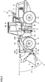
- Fig. 1 is a side view of wheel loader 1 as an example of the work machine according to the embodiment.
- wheel loader 1 includes a vehicular body frame 2, a work implement 3, a traveling unit 4, and a cab 5.
- Vehicular body frame 2, cab 5 and the like constitute a vehicular body (a work machine main body) of wheel loader 1.
- Work implement 3 and traveling unit 4 are attached to the vehicular body of wheel loader 1.
- Traveling unit 4 cause the vehicular body of wheel loader 1 to travel and includes running wheels 4a and 4b.
- Wheel loader 1 is movable as running wheels 4a and 4b are rotationally driven, and also, can perform a desired work using work implement 3.
- Vehicular body frame 2 includes a front frame 2a and a rear frame 2b. Front frame 2a and rear frame 2b are attached to each other so as to be pivotable in a left-right direction.
- a pair of steering cylinders 11 is attached across front frame 2a and rear frame 2b. Each steering cylinder 11 is a hydraulic cylinder. As each steering cylinder 11 extends and contracts by hydraulic oil from a steering pump (not shown), the traveling direction of wheel loader 1 is laterally changed.
- a front-rear direction of wheel loader 1 In the present specification, the direction in which wheel loader 1 travels straightforward is referred to as a front-rear direction of wheel loader 1.
- the front-rear direction of wheel loader 1 the side where work implement 3 is located with respect to vehicular body frame 2 is referred to as a frontward direction, and the side opposite to the frontward direction is referred to as a rearward direction.
- the left-right direction of wheel loader 1 is orthogonal to the front-rear direction in a plan view of wheel loader 1 situated on a flat ground.
- the right side and the left side in the left-right direction in facing forward are defined as a right direction and a left direction, respectively.
- a top-bottom direction of wheel loader 1 is orthogonal to a plane defined by the front-rear direction and the left-right direction. In the top-bottom direction, the ground side is defined as a lower side and the sky side is defined as an upper side.
- Work implement 3 and a pair of left and right running wheels (front wheels) 4a are attached to front frame 2a.
- Work implement 3 is disposed on the front side of the vehicular body.
- Work implement 3 is driven by hydraulic oil from a work implement pump 25 (see Fig. 2 ).
- Work implement pump 25 is a hydraulic pump that is driven by an engine 20 to discharge hydraulic oil for operating work implement 3.
- Work implement 3 includes a boom 14 and a bucket 6 that serves as a work tool.
- Bucket 6 is disposed at the distal end of work implement 3.
- Bucket 6 is an example of an attachment detachably attached to the distal end of boom 14. Depending on the type of work, the attachment is replaced with a grapple, a fork, a plow, or the like.
- a proximal end portion of boom 14 is attached by a boom pin 9 to front frame 2a so as to be rotatable.
- a bucket pin 17 located at a distal end of boom 14 bucket 6 is attached to boom 14 so as to be rotatable.
- Front frame 2a and boom 14 are coupled to each other by a pair of boom cylinders 16.
- Each boom cylinder 16 is a hydraulic cylinder.
- Each boom cylinder 16 has a proximal end attached to front frame 2a and a distal end attached to boom 14.
- boom 14 is raised and lowered.
- Boom cylinder 16 rotationally drives boom 14 to be raised and lowered about boom pin 9.
- Work implement 3 further includes a bell crank 18, a bucket cylinder 19, and a link 15.
- a support pin 18a located substantially in the center of boom 14, bell crank 18 is supported on boom 14 so as to be rotatable.
- Bucket cylinder 19 couples bell crank 18 to front frame 2a.
- Link 15 is coupled to a coupling pin 18c provided at a distal end portion of bell crank 18.
- Link 15 couples bell crank 18 and bucket 6.
- Bucket cylinder 19 is a hydraulic cylinder and serves as a work tool cylinder. Bucket cylinder 19 has a proximal end attached to front frame 2a. Bucket cylinder 19 has a distal end attached to a coupling pin 18b provided at a proximal end portion of bell crank 18. When bucket cylinder 19 extends and contracts by hydraulic oil from work implement pump 25 (see Fig. 2 ), bucket 6 pivots up and down. Bucket cylinder 19 drives bucket 6 to rotate about bucket pin 17.
- Cab 5 and a pair of left and right running wheels (rear wheels) 4b are attached to rear frame 2b.
- Cab 5 is disposed behind boom 14.
- Cab 5 is placed on vehicular body frame 2.
- a seat on which an operator sits, an operation apparatus (described later), and the like are disposed inside cab 5.
- IMU 66 Inside cab 5, an inertial measurement unit (IMU) 66 is disposed. IMU 66 detects the inclination of vehicular body frame 2. IMU 66 detects inclination angles of vehicular body frame 2 with respect to the front-rear direction and the left-right direction. IMU 66 detects the inclination of the vehicular body of wheel loader 1 with respect to the vertical direction.
- An engine hood 7 is disposed behind cab 5.
- Engine hood 7 covers the upper side and both sides of the accommodation space in which engine 20 ( Fig. 2 ) and the like are accommodated.
- An air cleaner 12 and an exhaust pipe 13 protrude upward from the upper surface of engine hood 7.
- a rear face grille 8 is disposed behind engine hood 7.
- Rear face grille 8 covers the accommodation space from behind.
- the rear surface of rear face grille 8 is provided with an intake port that allows communication between the inside and the outside of the accommodation space. Through this intake port, air is supplied into the accommodation space.
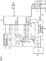
- Fig. 2 is a schematic block diagram showing a configuration of the entire system including wheel loader 1 according to an embodiment.
- Wheel loader 1 includes engine 20, a motive power extraction unit 22, a motive power transmission mechanism 23, a cylinder driving unit 24, a first angle detector 29, a second angle detector 48, a pivot mechanism 60, and a first processor 30 (a controller).
- Engine 20 is a diesel engine, for example.
- Engine 20 is accommodated in the accommodation space covered by engine hood 7 ( Fig. 1 ).
- An output from engine 20 is controlled by adjusting the amount of fuel to be injected into a cylinder of engine 20.
- Engine 20 is provided with a rotation sensor 32.
- Rotation sensor 32 detects the rotation speed of the rotation shaft inside engine 20 and outputs a detection signal indicating the rotation speed to first processor 30.
- Motive power extraction unit 22 is an apparatus that distributes the output from engine 20 to motive power transmission mechanism 23 and cylinder driving unit 24.
- Motive power transmission mechanism 23 is a mechanism that transmits the driving force from engine 20 to a front wheel 4a and a rear wheel 4b, and serves as a transmission, for example.
- both front wheels 4a attached to front frame 2a and rear wheels 4b attached to rear frame 2b constitute driving wheels that receive driving force to cause wheel loader 1 to travel.
- Motive power transmission mechanism 23 changes the speed of rotation of an input shaft 21 and outputs the resultant rotation to an output shaft 23a.
- a vehicle speed detection unit 27 for detecting a vehicle speed of wheel loader 1 is attached to output shaft 23a of motive power transmission mechanism 23.
- Wheel loader 1 includes vehicle speed detection unit 27.
- Vehicle speed detection unit 27 is a vehicle speed sensor, for example. Vehicle speed detection unit 27 detects the rotation speed of output shaft 23a to thereby detect the speed of movement of wheel loader 1 by traveling unit 4 ( Fig. 1 ). Vehicle speed detection unit 27 functions as a rotation sensor for detecting the rotation speed of output shaft 23a. Vehicle speed detection unit 27 functions as a movement detector that detects the movement by traveling unit 4. Vehicle speed detection unit 27 outputs a detection signal showing the vehicle speed of wheel loader 1 to first processor 30.
- a front axle 41 is connected to output shaft 23a.
- the driving force generated by engine 20 is transmitted to front axle 41.
- Left and right front wheels 4a are attached to respective both ends of front axle 41.
- the driving force is transmitted from front axle 41 to the pair of left and right front wheels 4a.
- Front axle 41 is supported by front frame 2a.
- Each front wheel 4a is attached via front axle 41 to front frame 2a, which forms a part of the vehicular body of wheel loader 1, such that each front wheel 4a is rotatable with respect to front frame 2a.
- Pivot mechanism 60 couples front frame 2a and rear frame 2b to each other so as to be pivotable.
- Front frame 2a is pivoted with respect to rear frame 2b by extension and contraction of an articulation cylinder coupled between front frame 2a and rear frame 2b.
- Front frame 2a can be angled with respect to rear frame 2b.
- the turning radius difference between front wheel 4a and rear wheel 4b can be reduced to thereby reduce a radius of revolution in revolution of wheel loader 1.
- Pivot mechanism 60 is provided with an articulation angle sensor 61.
- Articulation angle sensor 61 detects an articulation angle that is formed by front frame 2a and rear frame 2b. Articulation angle sensor 61 outputs a detection signal indicating the articulation angle to first processor 30.
- a rear propeller shaft 43 is connected to output shaft 23a.
- Rear propeller shaft 43 has a rear end provided with a coupling portion 44.
- a rear axle 42 is connected to coupling portion 44.
- Rear axle 42 is connected to output shaft 23a via rear propeller shaft 43.
- the driving force generated by engine 20 is transmitted to rear axle 42.
- Left and right rear wheels 4b are attached to respective both ends of rear axle 42.
- Driving force is transmitted from rear axle 42 to the pair of left and right rear wheels 4b.
- Rear axle 42 is supported by rear frame 2b.
- Each rear wheel 4b is attached via rear axle 42 to rear frame 2b, which forms a part of the vehicular body of wheel loader 1, such that each rear wheel 4b is rotatable with respect to rear frame 2b.
- Fig. 2 schematically shows an example of a structure for transmitting driving force generated by engine 20 to front wheel 4a and rear wheel 4b.
- the structure for transmitting motive power from engine 20 to front wheel 4a and rear wheel 4b is not limited to the above-described example.
- motive power transmission mechanism 23 may include a transmission and a transfer for distributing the driving force to the front and rear shafts, and may be configured to transmit driving force from one end of the output shaft of the transfer to front wheel 4a and to transmit driving force from the other end of the output shaft of the transfer to rear wheel 4b.
- Wheel loader 1 has a rear axle oscillation mechanism.
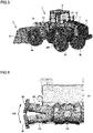
- Fig. 3 is a perspective view showing rear wheels 4b in an oscillatable state.
- Fig. 3 shows wheel loader 1 viewed from behind on the left side.
- Fig. 4 is a diagram showing a roll motion of rear axle 42 with respect to the vehicular body.
- Fig. 4 shows rear axle 42 viewed from behind.
- the rear axle oscillation mechanism serves to keep the vehicular body horizontally when wheel loader 1 travels on an uneven road surface or a road surface inclined in the vehicle width direction.
- rear axle 42 coupling the pair of rear wheels 4b to each other is supported by rear frame 2b so as to be swingable about coupling portion 44.
- rear axle 42 is capable of undergoing a roll motion such that rear axle 42 is inclined in both directions with respect to the horizontal axis extending in the front-rear direction of the vehicular body, for example, the center of rotation of output shaft 23a or the center of rotation of rear propeller shaft 43.
- Coupling portion 44 ( Fig. 2 ) is an example of a coupling device that supports rear axle 42 to be swingable about the horizontal axis such that rear axle 42 freely oscillates about the horizontal axis.
- Rear wheel attachment portions 46 are provided at both the left and right end portions of rear axle 42.
- Left and right rear wheels 4b are attached to respective left and right rear wheel attachment portions 46.
- rear wheels 4b move up and down integrally with rear axle 42 as indicated by double-headed arrow AR in Fig. 3 .
- a total of four running wheels including one pair of left and right front wheels 4a and one pair of left and right rear wheels 4b can be brought into contact with the ground, and thereby, the driving force of wheel loader 1 can be reliably transmitted to the ground.
- cylinder driving unit 24 includes work implement pump 25 and a control valve 26.
- the output from engine 20 is transmitted to work implement pump 25 through motive power extraction unit 22.
- the hydraulic oil discharged from work implement pump 25 is supplied to boom cylinder 16 and bucket cylinder 19 through control valve 26.
- a sensor 33 detects the angle of a swash plate of work implement pump 25. Sensor 33 outputs a detection signal indicating the angle of the swash plate of work implement pump 25 to first processor 30.
- a pressure sensor 34 detects the pressure discharged from work implement pump 25. Pressure sensor 34 outputs a detection signal indicating the pressure discharged from work implement pump 25 to first processor 30.
- First hydraulic pressure detectors 28a and 28b for detecting hydraulic pressure in an oil chamber of boom cylinder 16 are attached to boom cylinder 16.
- Wheel loader 1 includes first hydraulic pressure detectors 28a and 28b.
- First hydraulic pressure detectors 28a and 28b include a pressure sensor 28a for detecting head pressure, and a pressure sensor 28b for detecting bottom pressure, for example.
- Pressure sensor 28a is attached to the head side of boom cylinder 16. Pressure sensor 28a can detect the pressure (head pressure) of the hydraulic oil in the cylinder-head-side oil chamber of boom cylinder 16. Pressure sensor 28a outputs a detection signal showing the head pressure of boom cylinder 16 to first processor 30.
- Pressure sensor 28b is attached to the bottom side of boom cylinder 16. Pressure sensor 28b can detect the pressure (bottom pressure) of the hydraulic oil in the cylinder-bottom-side oil chamber of boom cylinder 16. Pressure sensor 28b outputs a detection signal showing the bottom pressure of boom cylinder 16 to first processor 30.
- First angle detector 29 is, for example, a potentiometer attached to boom pin 9. First angle detector 29 detects a boom angle showing a lift angle of boom 14. First angle detector 29 outputs a detection signal showing the boom angle to first processor 30.
- a boom reference line A is a straight line passing through the center of boom pin 9 and the center of bucket pin 17.
- a boom angle ⁇ 1 is an angle formed by a horizontal line H extending forward from the center of boom pin 9 and boom reference line A.
- boom angle ⁇ 1 0°.
- boom angle ⁇ 1 is positive.
- boom angle ⁇ 1 is negative.
- First angle detector 29 may be a stroke sensor disposed in boom cylinder 16.
- Second angle detector 48 is, for example, a potentiometer attached to support pin 18a. Second angle detector 48 detects a bucket angle indicating an angle of bucket 6 with respect to boom 14. Second angle detector 48 outputs a detection signal indicating the bucket angle to first processor 30.
- a bucket reference line B is a straight line passing through the center of bucket pin 17 and a cutting edge 6a of bucket 6.
- a bucket angle ⁇ 2 is an angle formed by boom reference line A and bucket reference line B.
- bucket angle ⁇ 2 0°.
- bucket angle ⁇ 2 is positive.
- bucket angle ⁇ 2 is negative.
- Second angle detector 48 may detect bucket angle ⁇ 2 by detecting an angle of bell crank 18 with respect to boom 14 (hereinafter referred to as a bell crank angle).
- the bell crank angle is formed by: a straight line passing through the center of support pin 18a and the center of coupling pin 18b; and boom reference line A.
- Second angle detector 48 may be a potentiometer or a proximity switch attached to bucket pin 17.
- second angle detector 48 may be a stroke sensor disposed on bucket cylinder 19.
- IMU 66 outputs a detection signal to first processor 30, which indicates the angle of the inclination of the vehicular body of wheel loader 1 with respect to the vertical direction.
- wheel loader 1 includes an operation device 49 inside cab 5.
- Operation device 49 includes: an operation member 49a operated by an operator; and a detection sensor 49b that detects the position of operation member 49a and outputs the detection result to first processor 30.
- Operation device 49 is operated by the operator to give instructions to: switch the movement of the vehicle between forward movement and rearward movement; set the target rotational speed of engine 20; control the deceleration force of wheel loader 1; operate boom 14 to be raised and lowered; control a speed change from input shaft 21 to output shaft 23a in motive power transmission mechanism 23; cause bucket 6 to perform an excavation operation or a dumping operation; angle (articulate) front frame 2a relative to rear frame 2b via pivot mechanism 60; and the like.
- First processor 30 is configured of a microcomputer including a storage device such as a random access memory (RAM) and a read only memory (ROM), and a computing device such as a central processing unit (CPU).
- First processor 30 may be implemented as a part of the function of the controller of wheel loader 1 that controls the operations of engine 20, work implement 3 (boom cylinder 16, bucket cylinder 19, and the like), motive power transmission mechanism 23, and the like.
- First processor 30 receives inputs including mainly: a signal of the inclination angle of the vehicular body detected by IMU 66; a signal of boom angle ⁇ 1 detected by first angle detector 29; a signal of bucket angle ⁇ 2 detected by second angle detector 48; a signal of the head pressure of boom cylinder 16 detected by pressure sensor 28a; a signal of the bottom pressure of boom cylinder 16 detected by pressure sensor 28b; a signal of the articulation angle detected by articulation angle sensor 61; and a signal of the vehicle speed of wheel loader 1 detected by vehicle speed detection unit 27.
- First processor 30 includes a storage unit 30j.
- Storage unit 30j stores a program for controlling various operations of wheel loader 1.
- First processor 30 performs various processes for controlling the operation of wheel loader 1 based on the program stored in storage unit 30j.
- Storage unit 30j is a non-volatile memory and provided as an area in which necessary data is stored.
- Wheel loader 1 further includes an oscillation lock mechanism 40.
- oscillation lock mechanism 40 In response to a control signal from first processor 30, oscillation lock mechanism 40 is driven to lock rear axle 42 so as not to move relative to the vehicular body, to thereby prevent a roll motion of rear axle 42 with respect to the vehicular body.
- Fig. 5 is a schematic diagram showing the first example of oscillation lock mechanism 40.
- Oscillation lock mechanism 40 shown in Fig. 5 includes cylinders 81 and 82.
- Cylinder 81 is disposed to face a portion of rear axle 42 that is close to left rear wheel 4b with respect to coupling portion 44.
- Cylinder 82 is disposed to face a portion of rear axle 42 that is close to right rear wheel 4b with respect to coupling portion 44.
- Fig. 6 is a schematic diagram showing the state where oscillation lock mechanism 40 shown in Fig. 5 is driven.
- the piston rods of cylinders 81 and 82 protrude and the distal end portions of the piston rods come into contact with rear axle 42.
- the piston rods of cylinders 81 and 82 are pressed against rear axle 42 on both sides of coupling portion 44, to thereby prevent relative movement of rear axle 42 with respect to the vehicular body. In this way, rear axle 42 is locked to thereby prevent a roll motion of rear axle 42 with respect to the vehicular body.
- Fig. 7 is a schematic diagram showing the second example of oscillation lock mechanism 40.
- Oscillation lock mechanism 40 shown in Fig. 7 includes a brake disc 83 and a brake pad 84.
- Brake disc 83 is fixed to rear axle 42 and is rotatable integrally with rear axle 42 with respect to the vehicular body.
- Brake disc 83 has a flat plate shape.
- Brake pads 84 are disposed to sandwich plate-shaped brake disc 83 therebetween.
- brake pads 84 sandwich plate-shaped brake disc 83 from both sides to restrict the movement of brake disc 83. Since brake disc 83 is integrally fixed to rear axle 42, the relative movement of rear axle 42 with respect to the vehicular body is prevented. In this way, rear axle 42 is locked to thereby prevent a roll motion of rear axle 42 with respect to the vehicular body.
- First processor 30 shown in Fig. 2 has a function of locking the roll motion of rear axle 42 with respect to the vehicular body by driving oscillation lock mechanism 40.
- the functional blocks of first processor 30 having this function will be described below.
- Fig. 8 is a diagram showing functional blocks in first processor 30.
- first processor 30 includes, for example, a vehicular body information detection unit 36, a center-of-gravity calculation unit 37, a determination unit 38, and an instruction unit 39.
- Vehicular body information detection unit 36 detects information about the vehicular body of wheel loader 1. Vehicular body information detection unit 36 acquires: a detection signal of the vehicle speed of wheel loader 1 that is output from vehicle speed detection unit 27; a detection signal of the hydraulic pressure in boom cylinder 16 that is output from each of first hydraulic pressure detectors 28a and 28b; a detection signal of boom angle ⁇ 1 that is output from first angle detector 29; a detection signal of bucket angle ⁇ 2 that is output from second angle detector 48; a detection signal of the articulation angle that is output from articulation angle sensor 61; and a detection signal of the inclination angle of the vehicular body that is output from IMU 66.
- Boom angle ⁇ 1 and bucket angle ⁇ 2 the articulation angle, and the inclination angle of the vehicular body may be acquired by analyzing an image from a camera mounted on cab 5. Further, an IMU may be installed in work implement 3 to acquire boom angle ⁇ 1 and bucket angle ⁇ 2 based on the relativity between the result of detection by the IMU in work implement 3 and the result of detection by IMU 66 in the vehicular body.
- Center-of-gravity calculation unit 37 calculates the position of the center of gravity of the vehicular body of wheel loader 1 based on the acquired vehicular body information. Center-of-gravity calculation unit 37 further acquires a vertical line that is a virtual straight line passing through the center of gravity of the vehicular body and extending in the vertical direction. Center-of-gravity calculation unit 37 outputs the acquired information about the vertical line to determination unit 38.
- Determination unit 38 reads the information related to the specifications of the vehicular body of wheel loader 1 from storage unit 30j ( Fig. 2 ). Specifically, from storage unit 30j, determination unit 38 reads: the center of rotation of left and right front wheels 4a; and the position of the center of the roll motion of rear axle 42 with respect to the vehicular body. Based on the information related to the specifications of the vehicular body of wheel loader 1 and the articulation angle, determination unit 38 derives a region defined from the center of rotation of left and right front wheels 4a and the position of the center of the roll motion of rear axle 42. Determination unit 38 determines the stability of wheel loader 1 based on the positional relation between the derived region and the vertical line acquired from center-of-gravity calculation unit 37. Based on the determined stability, determination unit 38 determines whether or not to lock the roll motion of rear axle 42. Determination unit 38 outputs the determination result to instruction unit 39.
- instruction unit 39 When instruction unit 39 acquires the result of the determination to lock the roll motion of rear axle 42 from determination unit 38, it outputs a control signal for driving oscillation lock mechanism 40 to oscillation lock mechanism 40.
- Fig. 9 is a flowchart showing a flow of a process of locking the roll motion of rear axle 42.
- step S1 vehicular body information is first detected.
- First processor 30, specifically, vehicular body information detection unit 36 detects information about the vehicular body of wheel loader 1.
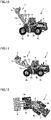
- Fig. 10 is a side view of wheel loader 1 showing an example of the vehicular body information.
- the vehicular body information includes the posture of work implement 3.
- boom 14 is located higher than that in Fig. 1 .
- Boom reference line A is located higher than horizontal line H in the posture shown in Fig. 10 .
- boom angle ⁇ 1 has a positive value.
- bucket 6 is moved in the dump direction as compared with Fig. 1 .
- bucket angle ⁇ 2 has a negative value.
- Vehicular body information detection unit 36 acquires a detection signal of boom angle ⁇ 1 from first angle detector 29. Vehicular body information detection unit 36 acquires a detection signal of bucket angle ⁇ 2 from second angle detector 48.
- the posture of work implement 3 is determined from boom angle ⁇ 1 and bucket angle ⁇ 2. The posture of work implement 3 influences the position of the center of gravity of the vehicular body of wheel loader 1. In the posture shown in Fig. 10 in which boom 14 is raised, the center of gravity of the vehicular body is located higher than that in the posture shown in Fig. 1 .
- Fig. 11 is a side view of wheel loader 1 showing an example of the vehicular body information.
- the vehicular body information includes the state of a load L mounted on work implement 3.
- boom angle ⁇ 1 has a positive value while bucket angle ⁇ 2 has a negative value.
- load L is mounted on bucket 6.
- Vehicular body information detection unit 36 acquires a detection signal of boom angle ⁇ 1 from first angle detector 29. Vehicular body information detection unit 36 acquires a detection signal of bucket angle ⁇ 2 from second angle detector 48. From first hydraulic pressure detectors 28a and 28b, vehicular body information detection unit 36 acquires detection signals of the head pressure and the bottom pressure of boom cylinder 16. The weight of load L mounted on work implement 3 is determined from boom angle ⁇ 1, bucket angle ⁇ 2, and the head pressure and the bottom pressure of boom cylinder 16.
- the weight of load L mounted on work implement 3 and the posture of work implement 3 on which load L is mounted influence the position of the center of gravity of the vehicular body of wheel loader 1.
- the center of gravity of the vehicular body is located higher than that in Fig. 1 .
- Fig. 12 is a plan view of wheel loader 1 showing an example of the vehicular body information.
- the vehicular body information includes an articulation angle.
- front frame 2a is angled with respect to rear frame 2b.
- Vehicular body information detection unit 36 acquires a detection signal of the articulation angle from articulation angle sensor 61.
- the articulation angle influences the region defined by: the center of rotation of left and right front wheels 4a; and the position of the center of the roll motion of rear axle 42. In a plan view, this region has an isosceles triangle shape when wheel loader 1 travels straightforward, but has a scalene triangle shape when wheel loader 1 is in an angled posture as shown in Fig. 12 .
- the articulation angle also influences the position of the center of gravity of the vehicular body of wheel loader 1.
- Fig. 13 is a rear view of wheel loader 1 showing an example of the vehicular body information.
- the vehicular body information includes the inclination of the vehicular body of wheel loader 1 with respect to the vertical direction.
- a ground GL on which wheel loader 1 shown in Fig. 13 travels is inclined, so that the vehicular body of wheel loader 1 is inclined with respect to the vertical direction.
- vehicular body information detection unit 36 acquires a detection signal of the inclination angle of the vehicular body.
- the inclination angle of the vehicular body influences the inclination of the vertical line with respect to the top-bottom direction of the vehicular body.
- the vertical line that is a virtual straight line passing through the center of gravity of the vehicular body of wheel loader 1 and extending in the vertical direction extends in the top-bottom direction of the vehicular body.
- the vertical line extends in a direction inclined with respect to the top-bottom direction of the vehicular body.
- the vehicular body information includes the vehicle speed of wheel loader 1.
- Vehicular body information detection unit 36 acquires a detection signal of the vehicle speed from vehicle speed detection unit 27. In particular, when the vehicle travels on an inclined surface as shown in Fig. 13 , the higher vehicle speed reduces the stability of the posture of wheel loader 1.
- first processor 30 acquires the position of the center of gravity of the vehicular body of wheel loader 1 from the vehicular body information detected in previous step S1, and then, acquires a vertical line that is a virtual straight line passing through the center of gravity and extending in the vertical direction.
- First processor 30 further derives information related to the specifications of the vehicular body of wheel loader 1, specifically, a region defined by vertices as: the center of rotation of left and right front wheels 4a; and the position of the center of the roll motion of rear axle 42 with respect to the vehicular body.
- First processor 30 further calculates the positional relation between the derived region and the vertical line.
- first processor 30 determines the stability of wheel loader 1. Specifically, first processor 30 determines whether the inclination of the vehicular body in the vertical direction increases or not due to oscillation of wheel loader 1 under its own weight.
- Fig. 14 is a diagram showing a vertical line of wheel loader 1 traveling on an inclined surface.
- Fig. 14 shows wheel loader 1 from behind as in Fig. 13 .
- Ground GL on which wheel loader 1 travels is inclined laterally.
- a vertical line g shown in Fig. 14 extends in a direction inclined with respect to the direction orthogonal to ground GL.
- Vertical line g extends at an inclination with respect to the top-bottom direction of the vehicular body of wheel loader 1.
- Fig. 15 is a diagram showing a positional relation between: regions R11, R12 in an oscillatable state; and vertical line g.
- Region R11 shown in Fig. 15 is defined by three vertices P1, P2, and P3.
- Vertex P1 is the center of rotation of right front wheel 4a.
- Vertex P1 indicates the center of a hub at the right end of front axle 41.
- Vertex P2 is the center of rotation of left front wheel 4a.
- Vertex P2 indicates the center of the hub at the left end of front axle 41.
- Vertex P3 indicates the position of the center of rear axle 42 in the left-right direction.
- Vertex P3 indicates the position of coupling portion 44 ( Fig. 2 ) between rear propeller shaft 43 and rear axle 42.
- Vertex P3 indicates the position of the center of the roll motion of rear axle 42 with respect to the vehicular body.
- Fig. 15 shows wheel loader 1 in a posture in which it travels straightforward, and region R11 has an isosceles triangle shape in this case. As described above, in the posture in which front frame 2a is angled (articulated) with respect to rear frame 2b, region R11 has a scalene triangle shape.
- vertical line g is inclined with respect to the top-bottom direction of the vehicular body as shown in Fig. 14 , vertical line g does not intersect with region R11 in the plane in which region R11 is defined. Vertical line g is located outside region R11. Since the vehicular body is inclined to the left, vertical line g is located outside region R11 on the left side.
- first processor 30, specifically, determination unit 38 determines that rear axle 42 undergoes a roll motion with respect to the vehicular body under the weight of the vehicular body, and as a result, the inclination of the vehicular body with respect to the vertical direction increases (YES in step S3).
- the vehicular body relatively rotates under its own weight from the posture shown in Fig. 14 in the counterclockwise direction with respect to rear axle 42, the vehicular body is inclined more significantly with respect to ground GL.
- the posture of the vehicular body becomes unstable.
- step S4 When it is determined that the stability of wheel loader 1 is low, the process proceeds to step S4, and the roll motion of rear axle 42 is locked.
- Instruction unit 39 of first processor 30 outputs a control signal for driving oscillation lock mechanism 40 to oscillation lock mechanism 40. Oscillation lock mechanism 40 having received the control signal is driven to thereby lock the roll motion of rear axle 42. As rear axle 42 cannot be relatively moved with respect to the vehicular body, the vehicular body is prevented from relatively rotating under its own weight with respect to rear axle 42.
- Fig. 16 is the first diagram showing the positional relation between a region R21 in an oscillation lock state and vertical line g. When the roll motion of rear axle 42 is locked, region R21 shown in Fig. 16 is defined.
- Region R21 is defined by four vertices P11, P12, P13, and P14.
- Vertex P11 is the center of rotation of right front wheel 4a. Vertex P11 indicates the center of a hub at the right end of front axle 41.
- Vertex P12 is the center of rotation of left front wheel 4a. Vertex P12 indicates the center of the hub at the left end of front axle 41.
- Vertex P13 is the center of rotation of right rear wheel 4b. Vertex P13 indicates the center of the hub (rear wheel attachment portion 46 in Fig. 4 ) at the right end of rear axle 42.
- Vertex P14 is the center of rotation of left rear wheel 4b. Vertex P14 indicates the center of the hub (rear wheel attachment portion 46 in Fig. 4 ) at the left end of rear axle 42.
- Region R21 has a rectangular shape.
- vertical line g intersects with region R21.
- Vertical line g is located inside region R21.
- Fig. 17 is the second diagram showing a positional relation between a region R22 in the oscillation lock state and vertical line g.
- Fig. 17 shows region R22 defined when left rear wheel 4b is in contact with the ground while right rear wheel 4b is not in contact with the ground. Note that region R11 described with reference to Fig. 16 is defined when both left and right rear wheels 4b are in contact with the ground.
- Region R22 is defined by three vertices P11, P12, and P14. Region R22 has a right triangular shape. As shown in Fig. 17 , in the plane in which region R22 is defined, vertical line g intersects with region R22. Vertical line g is located inside region R22.
- vertical line g is to intersect with: rectangular region R21 defined by the four wheels of wheel loader 1; or right-angled triangular region R22 defined by the three wheels contacting the ground even if one of rear wheels 4b is away from the ground.
- This increases the stability of wheel loader 1, so that an increase in inclination of the vehicular body with respect to ground GL is suppressed, and thus, the posture of the vehicular body can be stabilized.
- step S3 when it is determined in step S3 that the vehicular body is not inclined and rear axle 42 does not undergo a roll motion with respect to the vehicular body, or that the vehicular body is not so inclined as to increase the inclination of the vehicular body even if rear axle 42 undergoes a roll motion with respect to the vehicular body (NO in step S3), i.e., when it is determined that the stability of wheel loader 1 is sufficiently high, the process proceeds to step S5.
- instruction unit 39 does not output a control signal to oscillation lock mechanism 40, and the roll motion of rear axle 42 is not locked but remains in an oscillatable state. Then, the process ends.
- a region R12 indicated by a broken line is defined inside region R11 indicated by a solid line.
- Region R12 is defined by three vertices P4, P5, and P6.
- Vertices P4 and P5 are located rearward of front axle 41.
- Vertex P6 is located forward of rear axle 42.
- Vertex P4 is located more inside the vehicular body than vertex P1 is.
- Vertex P5 is located more inside the vehicular body than vertex P2 is.
- Vertex P6 is located more inside the vehicular body than vertex P3 is.
- Region R12 has an isosceles triangle shape similar to that of region R11. The isosceles triangle shape forming region R12 is shorter in base and height, and therefore, smaller in area than the isosceles triangle shape forming region R11.
- Region R12 can be set as a region for which sensor errors and the like are taken into consideration with respect to region R11.
- Region R11 is set based on the information related to the specifications of the vehicular body, and region R12 is set in consideration of an error with respect to region R11. Then, when it is determined that vertical line g does not intersect with region R12 and is located outside region R12, the roll motion of rear axle 42 can be locked. In this way, an increase in inclination of the vehicular body can be more reliably prevented.
- wheel loader 1 includes rear axle 42 and first processor 30.
- Rear axle 42 can undergo a roll motion with respect to an axis extending in the front-rear direction of a vehicular body.
- first processor 30 sets region R11 defined by: vertices P1 and P2 as the center of rotation of respective left and right front wheels 4a; and vertex P3 as the center of the roll motion of rear axle 42.
- First processor 30 sets vertical line g that is a virtual straight line passing through the center of gravity of the vehicular body and extending in the vertical direction.
- First processor 30 acquires the stability of the center of gravity of the vehicular body of wheel loader 1 from the positional relation between region R11 and vertical line g, and then, controls the roll motion of rear axle 42 with respect to the vehicular body based on the acquired stability.
- first processor 30 controls the roll motion of rear axle 42. Controlling the roll motion of rear axle 42 can suppress an increase in inclination of the vehicular body of wheel loader 1 with respect to the ground surface. Therefore, tipping over of wheel loader 1 including rear axle 42 capable of undergoing a roll motion with respect to the vehicular body can be prevented.
- first processor 30 acquires vertical line g in consideration of the inclination of the vehicular body with respect to the vertical direction. By acquiring vertical line g in this way, it can be more accurately determined whether or not to control the roll motion of rear axle 42 based on the positional relation between region R11 and vertical line g.
- first processor 30 acquires the position of the center of gravity of the vehicular body in consideration of the posture of work implement 3 and the state of load L mounted on work implement 3. By acquiring the position of the center of gravity in this way, it can be more accurately determined whether or not to control the roll motion of rear axle 42 based on the positional relation between region R11 and vertical line g.
- first processor 30 calculates region R11 from the angle formed by front frame 2a and rear frame 2b. By calculating region R11 in this way, it can be more accurately determined whether or not to control the roll motion of rear axle 42 based on the positional relation between region R11 and vertical line g. First processor 30 can acquire the position of the center of gravity of the vehicular body using the articulation angle and can calculate region R11 also using the articulation angle. Thus, it can be further more accurately determined whether or not to control the roll motion of rear axle 42 based on the positional relation between region R11 and vertical line g.
- wheel loader 1 further includes oscillation lock mechanism 40 that locks the roll motion of rear axle 42.
- First processor 30 outputs a control signal for driving oscillation lock mechanism 40, to thereby allow easy control for locking the roll motion of rear axle 42.
- first processor 30 determines that the inclination of the vehicular body with respect to the vertical direction increases as a result of the roll motion of rear axle 42 with respect to the vehicular body under the weight of the vehicular body
- first processor 30 drives oscillation lock mechanism 40. Locking the roll motion of rear axle 42 can suppress an increase in inclination of the vehicular body of wheel loader 1 with respect to the ground surface, and thus, can prevent tipping over of wheel loader 1 including rear axle 42 capable of undergoing a roll motion with respect to the vehicular body.
- first processor 30 drives oscillation lock mechanism 40. Thereby, it can be more accurately determined whether or not to drive oscillation lock mechanism 40 based on the positional relation between vertical line g and region R11.
- region R11 in the oscillatable state is defined from: the center of rotation of left and right front wheels 4a; and the position of the center of the roll motion of rear axle 42 with respect to the vehicular body.
- the vertex defining region R11 in rear axle 42 is not limited to vertex P3 corresponding to the position of the center of the roll motion but may be set at any position in rear axle 42.
- the vertices of region R11 may be set at both ends of rear axle 42.
- the vertex of region R11 may be set at one or both of left and right rear wheels 4b.
- Rear axle 42 extending in the left-right direction may form one side of region R11.
- the vertices defining region R11 in front axle 41 are not limited to left and right front wheels 4a, but may be set at any positions in front axle 41.
- wheel loader 1 As an example of the work machine. Without being limited to wheel loader 1, the concept of the embodiment may be applicable to any other work machine including rear wheels that can oscillate.
- 1 wheel loader 2 vehicular body frame, 2a front frame, 2b rear frame, 3 work implement, 4 traveling unit, 4a front wheel, 4b rear wheel, 5 cab, 6 bucket, 14 boom, 20 engine, 27 vehicle speed detection unit, 28a, 28b first hydraulic pressure detector, 29 first angle detector, 30 first processor, 36 vehicular body information detection unit, 37 center-of-gravity calculation unit, 38 determination unit, 39 instruction unit, 40 oscillation lock mechanism, 41 front axle, 42 rear axle, 43 rear propeller shaft, 44 coupling portion, 46 rear wheel attachment portion, 48 second angle detector, 61 articulation angle sensor, 81, 82 cylinder, 83 brake disc, 84 brake pad, A boom reference line, AR double-headed arrow, B bucket reference line, GL ground, H horizontal line, L load, P1, P2, P3, P4, P5, P6, P11, P12, P13, P14 vertex, R11, R12, R21, R22 region, g vertical line.
Landscapes
- Engineering & Computer Science (AREA)
- Mining & Mineral Resources (AREA)
- Civil Engineering (AREA)
- General Engineering & Computer Science (AREA)
- Structural Engineering (AREA)
- Mechanical Engineering (AREA)
- Chemical & Material Sciences (AREA)
- Combustion & Propulsion (AREA)
- Transportation (AREA)
- Operation Control Of Excavators (AREA)
- Component Parts Of Construction Machinery (AREA)
- Arrangement And Driving Of Transmission Devices (AREA)
- Vehicle Body Suspensions (AREA)
Abstract
Description
- The present disclosure relates to a work machine.
-
Japanese Patent Laying-Open No. 05-86636 - PTL 1:
Japanese Patent Laying-Open No. 5-86636 - A work machine such as a wheel loader includes a rear axle oscillation mechanism that causes rear wheels to be inclined leftward and rightward along unevenness of the ground, to thereby allow four wheels including front and rear wheels to continuously contact the ground so as to reliably transmit the driving force to the ground.
- The above-mentioned literature discloses a work vehicle including a rear axle that does not rotate with respect to its vehicular body, and fails to consider prevention of tipping over of a work machine that can oscillate.
- The present disclosure provides a technique that can prevent tipping over of a work machine including a rear axle capable of undergoing a roll motion with respect to a vehicular body.
- According to the present disclosure, a work machine is provided that includes: a vehicular body; and a rear axle attached to the vehicular body to be capable of undergoing a roll motion with respect to an axis extending in a front-rear direction of the vehicular body. The work machine includes a controller. The controller acquires stability of a center of gravity of the vehicular body and controls the roll motion of the rear axle with respect to the vehicular body based on the stability of the center of gravity.
- According to the present disclosure, tipping over of a work machine including a rear axle capable of undergoing a roll motion with respect to a vehicular body can be prevented.
-
-
Fig. 1 is a side view of a wheel loader as an example of a work machine according to an embodiment. -
Fig. 2 is a schematic block diagram showing a configuration of the entire system including the wheel loader according to an embodiment. -
Fig. 3 is a perspective view showing rear wheels in an oscillatable state. -
Fig. 4 is a diagram showing a roll motion of a rear axle with respect to a vehicular body. -
Fig. 5 is a schematic diagram showing a first example of an oscillation lock mechanism. -
Fig. 6 is a schematic diagram showing the state where the oscillation lock mechanism shown inFig. 5 is driven. -
Fig. 7 is a schematic diagram showing a second example of the oscillation lock mechanism. -
Fig. 8 is a diagram showing functional blocks in a first processor. -
Fig. 9 is a flowchart showing a flow of a process of locking the roll motion of the rear axle. -
Fig. 10 is a side view of the wheel loader showing an example of vehicular body information. -
Fig. 11 is a side view of the wheel loader showing an example of the vehicular body information. -
Fig. 12 is a plan view of the wheel loader showing an example of the vehicular body information. -
Fig. 13 is a rear view of the wheel loader showing an example of the vehicular body information. -
Fig. 14 is a diagram showing a vertical line of the wheel loader traveling on an inclined surface. -
Fig. 15 is a diagram showing a positional relation between a region in an oscillatable state and the vertical line. -
Fig. 16 is a diagram showing a positional relation between a region in an oscillation lock state and the vertical line. -
Fig. 17 is a diagram showing a positional relation between the region in the oscillation lock state and the vertical line. - Embodiments will be hereinafter described with reference to the accompanying drawings. In the following description, the same components are denoted by the same reference characters. Names and functions thereof are also the same. Accordingly, the detailed description thereof will not be repeated.
- In an embodiment, a
wheel loader 1 will be described as an example of a work machine.Fig. 1 is a side view ofwheel loader 1 as an example of the work machine according to the embodiment. - As shown in
Fig. 1 ,wheel loader 1 includes a vehicular body frame 2, a work implement 3, a traveling unit 4, and acab 5. Vehicular body frame 2,cab 5 and the like constitute a vehicular body (a work machine main body) ofwheel loader 1. Work implement 3 and traveling unit 4 are attached to the vehicular body ofwheel loader 1. - Traveling unit 4 cause the vehicular body of
wheel loader 1 to travel and includes runningwheels Wheel loader 1 is movable as runningwheels work implement 3. - Vehicular body frame 2 includes a
front frame 2a and arear frame 2b.Front frame 2a andrear frame 2b are attached to each other so as to be pivotable in a left-right direction. A pair of steering cylinders 11 is attached acrossfront frame 2a andrear frame 2b. Each steering cylinder 11 is a hydraulic cylinder. As each steering cylinder 11 extends and contracts by hydraulic oil from a steering pump (not shown), the traveling direction ofwheel loader 1 is laterally changed. - In the present specification, the direction in which
wheel loader 1 travels straightforward is referred to as a front-rear direction ofwheel loader 1. In the front-rear direction ofwheel loader 1, the side wherework implement 3 is located with respect to vehicular body frame 2 is referred to as a frontward direction, and the side opposite to the frontward direction is referred to as a rearward direction. The left-right direction ofwheel loader 1 is orthogonal to the front-rear direction in a plan view ofwheel loader 1 situated on a flat ground. The right side and the left side in the left-right direction in facing forward are defined as a right direction and a left direction, respectively. A top-bottom direction ofwheel loader 1 is orthogonal to a plane defined by the front-rear direction and the left-right direction. In the top-bottom direction, the ground side is defined as a lower side and the sky side is defined as an upper side. - Work implement 3 and a pair of left and right running wheels (front wheels) 4a are attached to
front frame 2a.Work implement 3 is disposed on the front side of the vehicular body.Work implement 3 is driven by hydraulic oil from a work implement pump 25 (seeFig. 2 ).Work implement pump 25 is a hydraulic pump that is driven by anengine 20 to discharge hydraulic oil foroperating work implement 3.Work implement 3 includes aboom 14 and abucket 6 that serves as a work tool.Bucket 6 is disposed at the distal end of work implement 3.Bucket 6 is an example of an attachment detachably attached to the distal end ofboom 14. Depending on the type of work, the attachment is replaced with a grapple, a fork, a plow, or the like. - A proximal end portion of
boom 14 is attached by a boom pin 9 tofront frame 2a so as to be rotatable. By abucket pin 17 located at a distal end ofboom 14,bucket 6 is attached to boom 14 so as to be rotatable. -
Front frame 2a andboom 14 are coupled to each other by a pair ofboom cylinders 16. Eachboom cylinder 16 is a hydraulic cylinder. Eachboom cylinder 16 has a proximal end attached tofront frame 2a and a distal end attached toboom 14. Asboom cylinder 16 extends and contracts by hydraulic oil from work implement pump 25 (seeFig. 2 ),boom 14 is raised and lowered.Boom cylinder 16 rotationally drives boom 14 to be raised and lowered about boom pin 9. - Work implement 3 further includes a
bell crank 18, abucket cylinder 19, and alink 15. By asupport pin 18a located substantially in the center ofboom 14, bell crank 18 is supported onboom 14 so as to be rotatable.Bucket cylinder 19 couples bell crank 18 tofront frame 2a.Link 15 is coupled to acoupling pin 18c provided at a distal end portion ofbell crank 18.Link 15 couples bell crank 18 andbucket 6. -
Bucket cylinder 19 is a hydraulic cylinder and serves as a work tool cylinder.Bucket cylinder 19 has a proximal end attached tofront frame 2a.Bucket cylinder 19 has a distal end attached to acoupling pin 18b provided at a proximal end portion ofbell crank 18. Whenbucket cylinder 19 extends and contracts by hydraulic oil from work implement pump 25 (seeFig. 2 ),bucket 6 pivots up and down.Bucket cylinder 19drives bucket 6 to rotate aboutbucket pin 17. -
Cab 5 and a pair of left and right running wheels (rear wheels) 4b are attached torear frame 2b.Cab 5 is disposed behindboom 14.Cab 5 is placed on vehicular body frame 2. A seat on which an operator sits, an operation apparatus (described later), and the like are disposed insidecab 5. - Inside
cab 5, an inertial measurement unit (IMU) 66 is disposed.IMU 66 detects the inclination of vehicular body frame 2.IMU 66 detects inclination angles of vehicular body frame 2 with respect to the front-rear direction and the left-right direction.IMU 66 detects the inclination of the vehicular body ofwheel loader 1 with respect to the vertical direction. - An
engine hood 7 is disposed behindcab 5.Engine hood 7 covers the upper side and both sides of the accommodation space in which engine 20 (Fig. 2 ) and the like are accommodated. Anair cleaner 12 and anexhaust pipe 13 protrude upward from the upper surface ofengine hood 7. - A
rear face grille 8 is disposed behindengine hood 7.Rear face grille 8 covers the accommodation space from behind. The rear surface ofrear face grille 8 is provided with an intake port that allows communication between the inside and the outside of the accommodation space. Through this intake port, air is supplied into the accommodation space. -
Fig. 2 is a schematic block diagram showing a configuration of the entire system includingwheel loader 1 according to an embodiment. -
Wheel loader 1 includesengine 20, a motivepower extraction unit 22, a motivepower transmission mechanism 23, acylinder driving unit 24, afirst angle detector 29, asecond angle detector 48, apivot mechanism 60, and a first processor 30 (a controller). -
Engine 20 is a diesel engine, for example.Engine 20 is accommodated in the accommodation space covered by engine hood 7 (Fig. 1 ). An output fromengine 20 is controlled by adjusting the amount of fuel to be injected into a cylinder ofengine 20.Engine 20 is provided with arotation sensor 32.Rotation sensor 32 detects the rotation speed of the rotation shaft insideengine 20 and outputs a detection signal indicating the rotation speed tofirst processor 30. - Motive
power extraction unit 22 is an apparatus that distributes the output fromengine 20 to motivepower transmission mechanism 23 andcylinder driving unit 24. Motivepower transmission mechanism 23 is a mechanism that transmits the driving force fromengine 20 to afront wheel 4a and arear wheel 4b, and serves as a transmission, for example. Inwheel loader 1, bothfront wheels 4a attached tofront frame 2a andrear wheels 4b attached torear frame 2b constitute driving wheels that receive driving force to causewheel loader 1 to travel. - Motive
power transmission mechanism 23 changes the speed of rotation of aninput shaft 21 and outputs the resultant rotation to anoutput shaft 23a. A vehiclespeed detection unit 27 for detecting a vehicle speed ofwheel loader 1 is attached tooutput shaft 23a of motivepower transmission mechanism 23.Wheel loader 1 includes vehiclespeed detection unit 27. - Vehicle
speed detection unit 27 is a vehicle speed sensor, for example. Vehiclespeed detection unit 27 detects the rotation speed ofoutput shaft 23a to thereby detect the speed of movement ofwheel loader 1 by traveling unit 4 (Fig. 1 ). Vehiclespeed detection unit 27 functions as a rotation sensor for detecting the rotation speed ofoutput shaft 23a. Vehiclespeed detection unit 27 functions as a movement detector that detects the movement by traveling unit 4. Vehiclespeed detection unit 27 outputs a detection signal showing the vehicle speed ofwheel loader 1 tofirst processor 30. - A
front axle 41 is connected tooutput shaft 23a. The driving force generated byengine 20 is transmitted tofront axle 41. Left and rightfront wheels 4a are attached to respective both ends offront axle 41. The driving force is transmitted fromfront axle 41 to the pair of left and rightfront wheels 4a.Front axle 41 is supported byfront frame 2a. Eachfront wheel 4a is attached viafront axle 41 tofront frame 2a, which forms a part of the vehicular body ofwheel loader 1, such that eachfront wheel 4a is rotatable with respect tofront frame 2a. -
Pivot mechanism 60 couplesfront frame 2a andrear frame 2b to each other so as to be pivotable.Front frame 2a is pivoted with respect torear frame 2b by extension and contraction of an articulation cylinder coupled betweenfront frame 2a andrear frame 2b.Front frame 2a can be angled with respect torear frame 2b. By angling (articulating)front frame 2a with respect torear frame 2b, the turning radius difference betweenfront wheel 4a andrear wheel 4b can be reduced to thereby reduce a radius of revolution in revolution ofwheel loader 1. -
Pivot mechanism 60 is provided with anarticulation angle sensor 61.Articulation angle sensor 61 detects an articulation angle that is formed byfront frame 2a andrear frame 2b.Articulation angle sensor 61 outputs a detection signal indicating the articulation angle tofirst processor 30. - A
rear propeller shaft 43 is connected tooutput shaft 23a.Rear propeller shaft 43 has a rear end provided with acoupling portion 44. Arear axle 42 is connected to couplingportion 44.Rear axle 42 is connected tooutput shaft 23a viarear propeller shaft 43. The driving force generated byengine 20 is transmitted torear axle 42. Left and rightrear wheels 4b are attached to respective both ends ofrear axle 42. Driving force is transmitted fromrear axle 42 to the pair of left and rightrear wheels 4b.Rear axle 42 is supported byrear frame 2b. Eachrear wheel 4b is attached viarear axle 42 torear frame 2b, which forms a part of the vehicular body ofwheel loader 1, such that eachrear wheel 4b is rotatable with respect torear frame 2b. -
Fig. 2 schematically shows an example of a structure for transmitting driving force generated byengine 20 tofront wheel 4a andrear wheel 4b. The structure for transmitting motive power fromengine 20 tofront wheel 4a andrear wheel 4b is not limited to the above-described example. For example, motivepower transmission mechanism 23 may include a transmission and a transfer for distributing the driving force to the front and rear shafts, and may be configured to transmit driving force from one end of the output shaft of the transfer tofront wheel 4a and to transmit driving force from the other end of the output shaft of the transfer torear wheel 4b. -
Wheel loader 1 has a rear axle oscillation mechanism.Fig. 3 is a perspective view showingrear wheels 4b in an oscillatable state.Fig. 3 showswheel loader 1 viewed from behind on the left side.Fig. 4 is a diagram showing a roll motion ofrear axle 42 with respect to the vehicular body.Fig. 4 showsrear axle 42 viewed from behind. - The rear axle oscillation mechanism serves to keep the vehicular body horizontally when
wheel loader 1 travels on an uneven road surface or a road surface inclined in the vehicle width direction. Inwheel loader 1 having the rear axle oscillation mechanism, as shown inFig. 4 ,rear axle 42 coupling the pair ofrear wheels 4b to each other is supported byrear frame 2b so as to be swingable about couplingportion 44. As indicated by a double-headed arrow AR inFig. 4 ,rear axle 42 is capable of undergoing a roll motion such thatrear axle 42 is inclined in both directions with respect to the horizontal axis extending in the front-rear direction of the vehicular body, for example, the center of rotation ofoutput shaft 23a or the center of rotation ofrear propeller shaft 43. Coupling portion 44 (Fig. 2 ) is an example of a coupling device that supportsrear axle 42 to be swingable about the horizontal axis such thatrear axle 42 freely oscillates about the horizontal axis. - Rear
wheel attachment portions 46 are provided at both the left and right end portions ofrear axle 42. Left and rightrear wheels 4b are attached to respective left and right rearwheel attachment portions 46. Whenrear axle 42 swings along the unevenness or the inclination of the road surface and inclines with respect to the vehicle width direction,rear wheels 4b move up and down integrally withrear axle 42 as indicated by double-headed arrow AR inFig. 3 . Thus, a total of four running wheels including one pair of left and rightfront wheels 4a and one pair of left and rightrear wheels 4b can be brought into contact with the ground, and thereby, the driving force ofwheel loader 1 can be reliably transmitted to the ground. - Referring back to
Fig. 2 ,cylinder driving unit 24 includes work implementpump 25 and acontrol valve 26. The output fromengine 20 is transmitted to work implementpump 25 through motivepower extraction unit 22. The hydraulic oil discharged from work implementpump 25 is supplied toboom cylinder 16 andbucket cylinder 19 throughcontrol valve 26. - A
sensor 33 detects the angle of a swash plate of work implementpump 25.Sensor 33 outputs a detection signal indicating the angle of the swash plate of work implementpump 25 tofirst processor 30. Apressure sensor 34 detects the pressure discharged from work implementpump 25.Pressure sensor 34 outputs a detection signal indicating the pressure discharged from work implementpump 25 tofirst processor 30. - First
hydraulic pressure detectors boom cylinder 16 are attached toboom cylinder 16.Wheel loader 1 includes firsthydraulic pressure detectors hydraulic pressure detectors pressure sensor 28a for detecting head pressure, and apressure sensor 28b for detecting bottom pressure, for example. -
Pressure sensor 28a is attached to the head side ofboom cylinder 16.Pressure sensor 28a can detect the pressure (head pressure) of the hydraulic oil in the cylinder-head-side oil chamber ofboom cylinder 16.Pressure sensor 28a outputs a detection signal showing the head pressure ofboom cylinder 16 tofirst processor 30.Pressure sensor 28b is attached to the bottom side ofboom cylinder 16.Pressure sensor 28b can detect the pressure (bottom pressure) of the hydraulic oil in the cylinder-bottom-side oil chamber ofboom cylinder 16.Pressure sensor 28b outputs a detection signal showing the bottom pressure ofboom cylinder 16 tofirst processor 30. -
First angle detector 29 is, for example, a potentiometer attached to boom pin 9.First angle detector 29 detects a boom angle showing a lift angle ofboom 14.First angle detector 29 outputs a detection signal showing the boom angle tofirst processor 30. - Specifically, as shown in
Fig. 1 , a boom reference line A is a straight line passing through the center of boom pin 9 and the center ofbucket pin 17. A boom angle θ1 is an angle formed by a horizontal line H extending forward from the center of boom pin 9 and boom reference line A. When boom reference line A is horizontal, boom angle θ1 = 0°. When boom reference line A is above horizontal line H, boom angle θ1 is positive. When boom reference line A is below horizontal line H, boom angle θ1 is negative. -
First angle detector 29 may be a stroke sensor disposed inboom cylinder 16. -
Second angle detector 48 is, for example, a potentiometer attached to supportpin 18a.Second angle detector 48 detects a bucket angle indicating an angle ofbucket 6 with respect toboom 14.Second angle detector 48 outputs a detection signal indicating the bucket angle tofirst processor 30. - Specifically, as shown in
Fig. 1 , a bucket reference line B is a straight line passing through the center ofbucket pin 17 and acutting edge 6a ofbucket 6. A bucket angle θ2 is an angle formed by boom reference line A and bucket reference line B. When cuttingedge 6a ofbucket 6 extends horizontally on the ground in the state wherebucket 6 is in contact with the ground, bucket angle θ2 = 0°. Whenbucket 6 is moved in a direction to be tilted (or upward), bucket angle θ2 is positive. Whenbucket 6 is moved in a direction for dumping (or downward), bucket angle θ2 is negative. -
Second angle detector 48 may detect bucket angle θ2 by detecting an angle of bell crank 18 with respect to boom 14 (hereinafter referred to as a bell crank angle). The bell crank angle is formed by: a straight line passing through the center ofsupport pin 18a and the center ofcoupling pin 18b; and boom reference line A.Second angle detector 48 may be a potentiometer or a proximity switch attached tobucket pin 17. Alternatively,second angle detector 48 may be a stroke sensor disposed onbucket cylinder 19. -
IMU 66 outputs a detection signal tofirst processor 30, which indicates the angle of the inclination of the vehicular body ofwheel loader 1 with respect to the vertical direction. - As shown in
Fig. 2 ,wheel loader 1 includes anoperation device 49 insidecab 5.Operation device 49 includes: anoperation member 49a operated by an operator; and adetection sensor 49b that detects the position ofoperation member 49a and outputs the detection result tofirst processor 30.Operation device 49 is operated by the operator to give instructions to: switch the movement of the vehicle between forward movement and rearward movement; set the target rotational speed ofengine 20; control the deceleration force ofwheel loader 1; operateboom 14 to be raised and lowered; control a speed change frominput shaft 21 tooutput shaft 23a in motivepower transmission mechanism 23; causebucket 6 to perform an excavation operation or a dumping operation; angle (articulate)front frame 2a relative torear frame 2b viapivot mechanism 60; and the like. -
First processor 30 is configured of a microcomputer including a storage device such as a random access memory (RAM) and a read only memory (ROM), and a computing device such as a central processing unit (CPU).First processor 30 may be implemented as a part of the function of the controller ofwheel loader 1 that controls the operations ofengine 20, work implement 3 (boom cylinder 16,bucket cylinder 19, and the like), motivepower transmission mechanism 23, and the like. -
First processor 30 receives inputs including mainly: a signal of the inclination angle of the vehicular body detected byIMU 66; a signal of boom angle θ1 detected byfirst angle detector 29; a signal of bucket angle θ2 detected bysecond angle detector 48; a signal of the head pressure ofboom cylinder 16 detected bypressure sensor 28a; a signal of the bottom pressure ofboom cylinder 16 detected bypressure sensor 28b; a signal of the articulation angle detected byarticulation angle sensor 61; and a signal of the vehicle speed ofwheel loader 1 detected by vehiclespeed detection unit 27. -
First processor 30 includes astorage unit 30j.Storage unit 30j stores a program for controlling various operations ofwheel loader 1.First processor 30 performs various processes for controlling the operation ofwheel loader 1 based on the program stored instorage unit 30j.Storage unit 30j is a non-volatile memory and provided as an area in which necessary data is stored. -
Wheel loader 1 further includes anoscillation lock mechanism 40. In response to a control signal fromfirst processor 30,oscillation lock mechanism 40 is driven to lockrear axle 42 so as not to move relative to the vehicular body, to thereby prevent a roll motion ofrear axle 42 with respect to the vehicular body. -
Fig. 5 is a schematic diagram showing the first example ofoscillation lock mechanism 40.Oscillation lock mechanism 40 shown inFig. 5 includescylinders Cylinder 81 is disposed to face a portion ofrear axle 42 that is close to leftrear wheel 4b with respect tocoupling portion 44.Cylinder 82 is disposed to face a portion ofrear axle 42 that is close to rightrear wheel 4b with respect tocoupling portion 44. -
Fig. 6 is a schematic diagram showing the state whereoscillation lock mechanism 40 shown inFig. 5 is driven. In the state whereoscillation lock mechanism 40 shown inFig. 6 is driven, the piston rods ofcylinders rear axle 42. The piston rods ofcylinders rear axle 42 on both sides ofcoupling portion 44, to thereby prevent relative movement ofrear axle 42 with respect to the vehicular body. In this way,rear axle 42 is locked to thereby prevent a roll motion ofrear axle 42 with respect to the vehicular body. -
Fig. 7 is a schematic diagram showing the second example ofoscillation lock mechanism 40.Oscillation lock mechanism 40 shown inFig. 7 includes abrake disc 83 and abrake pad 84.Brake disc 83 is fixed torear axle 42 and is rotatable integrally withrear axle 42 with respect to the vehicular body.Brake disc 83 has a flat plate shape.Brake pads 84 are disposed to sandwich plate-shapedbrake disc 83 therebetween. - In the state where
oscillation lock mechanism 40 shown inFig. 7 is driven,brake pads 84 sandwich plate-shapedbrake disc 83 from both sides to restrict the movement ofbrake disc 83. Sincebrake disc 83 is integrally fixed torear axle 42, the relative movement ofrear axle 42 with respect to the vehicular body is prevented. In this way,rear axle 42 is locked to thereby prevent a roll motion ofrear axle 42 with respect to the vehicular body. -
First processor 30 shown inFig. 2 has a function of locking the roll motion ofrear axle 42 with respect to the vehicular body by drivingoscillation lock mechanism 40. The functional blocks offirst processor 30 having this function will be described below. -
Fig. 8 is a diagram showing functional blocks infirst processor 30. As shown inFig. 8 ,first processor 30 includes, for example, a vehicular bodyinformation detection unit 36, a center-of-gravity calculation unit 37, adetermination unit 38, and aninstruction unit 39. - Vehicular body
information detection unit 36 detects information about the vehicular body ofwheel loader 1. Vehicular bodyinformation detection unit 36 acquires: a detection signal of the vehicle speed ofwheel loader 1 that is output from vehiclespeed detection unit 27; a detection signal of the hydraulic pressure inboom cylinder 16 that is output from each of firsthydraulic pressure detectors first angle detector 29; a detection signal of bucket angle θ2 that is output fromsecond angle detector 48; a detection signal of the articulation angle that is output fromarticulation angle sensor 61; and a detection signal of the inclination angle of the vehicular body that is output fromIMU 66. - Boom angle θ1 and bucket angle θ2, the articulation angle, and the inclination angle of the vehicular body may be acquired by analyzing an image from a camera mounted on
cab 5. Further, an IMU may be installed in work implement 3 to acquire boom angle θ1 and bucket angle θ2 based on the relativity between the result of detection by the IMU in work implement 3 and the result of detection byIMU 66 in the vehicular body. - Center-of-
gravity calculation unit 37 calculates the position of the center of gravity of the vehicular body ofwheel loader 1 based on the acquired vehicular body information. Center-of-gravity calculation unit 37 further acquires a vertical line that is a virtual straight line passing through the center of gravity of the vehicular body and extending in the vertical direction. Center-of-gravity calculation unit 37 outputs the acquired information about the vertical line todetermination unit 38. -
Determination unit 38 reads the information related to the specifications of the vehicular body ofwheel loader 1 fromstorage unit 30j (Fig. 2 ). Specifically, fromstorage unit 30j,determination unit 38 reads: the center of rotation of left and rightfront wheels 4a; and the position of the center of the roll motion ofrear axle 42 with respect to the vehicular body. Based on the information related to the specifications of the vehicular body ofwheel loader 1 and the articulation angle,determination unit 38 derives a region defined from the center of rotation of left and rightfront wheels 4a and the position of the center of the roll motion ofrear axle 42.Determination unit 38 determines the stability ofwheel loader 1 based on the positional relation between the derived region and the vertical line acquired from center-of-gravity calculation unit 37. Based on the determined stability,determination unit 38 determines whether or not to lock the roll motion ofrear axle 42.Determination unit 38 outputs the determination result toinstruction unit 39. - When
instruction unit 39 acquires the result of the determination to lock the roll motion ofrear axle 42 fromdetermination unit 38, it outputs a control signal for drivingoscillation lock mechanism 40 tooscillation lock mechanism 40. - The following describes a control method for locking
rear axle 42.Fig. 9 is a flowchart showing a flow of a process of locking the roll motion ofrear axle 42. - As shown in
Fig. 9 , in step S1, vehicular body information is first detected.First processor 30, specifically, vehicular bodyinformation detection unit 36, detects information about the vehicular body ofwheel loader 1. -
Fig. 10 is a side view ofwheel loader 1 showing an example of the vehicular body information. The vehicular body information includes the posture of work implement 3. Inwheel loader 1 shown inFig. 10 ,boom 14 is located higher than that inFig. 1 . Boom reference line A is located higher than horizontal line H in the posture shown inFig. 10 . In the posture shown inFig. 10 , boom angle θ1 has a positive value. Inwheel loader 1 shown inFig. 10 ,bucket 6 is moved in the dump direction as compared withFig. 1 . In the posture shown inFig. 10 , bucket angle θ2 has a negative value. - Vehicular body
information detection unit 36 acquires a detection signal of boom angle θ1 fromfirst angle detector 29. Vehicular bodyinformation detection unit 36 acquires a detection signal of bucket angle θ2 fromsecond angle detector 48. The posture of work implement 3 is determined from boom angle θ1 and bucket angle θ2. The posture of work implement 3 influences the position of the center of gravity of the vehicular body ofwheel loader 1. In the posture shown inFig. 10 in which boom 14 is raised, the center of gravity of the vehicular body is located higher than that in the posture shown inFig. 1 . -
Fig. 11 is a side view ofwheel loader 1 showing an example of the vehicular body information. The vehicular body information includes the state of a load L mounted on work implement 3. In the posture shown inFig. 11 , boom angle θ1 has a positive value while bucket angle θ2 has a negative value. Inwheel loader 1 shown inFig. 11 , load L is mounted onbucket 6. - Vehicular body
information detection unit 36 acquires a detection signal of boom angle θ1 fromfirst angle detector 29. Vehicular bodyinformation detection unit 36 acquires a detection signal of bucket angle θ2 fromsecond angle detector 48. From firsthydraulic pressure detectors information detection unit 36 acquires detection signals of the head pressure and the bottom pressure ofboom cylinder 16. The weight of load L mounted on work implement 3 is determined from boom angle θ1, bucket angle θ2, and the head pressure and the bottom pressure ofboom cylinder 16. - The weight of load L mounted on work implement 3 and the posture of work implement 3 on which load L is mounted influence the position of the center of gravity of the vehicular body of
wheel loader 1. In the state whereboom 14 is raised and load L is mounted onbucket 6 as shown inFig. 11 , the center of gravity of the vehicular body is located higher than that inFig. 1 . -
Fig. 12 is a plan view ofwheel loader 1 showing an example of the vehicular body information. The vehicular body information includes an articulation angle. Inwheel loader 1 shown inFig. 12 ,front frame 2a is angled with respect torear frame 2b. - Vehicular body
information detection unit 36 acquires a detection signal of the articulation angle fromarticulation angle sensor 61. The articulation angle influences the region defined by: the center of rotation of left and rightfront wheels 4a; and the position of the center of the roll motion ofrear axle 42. In a plan view, this region has an isosceles triangle shape whenwheel loader 1 travels straightforward, but has a scalene triangle shape whenwheel loader 1 is in an angled posture as shown inFig. 12 . The articulation angle also influences the position of the center of gravity of the vehicular body ofwheel loader 1. -
Fig. 13 is a rear view ofwheel loader 1 showing an example of the vehicular body information. The vehicular body information includes the inclination of the vehicular body ofwheel loader 1 with respect to the vertical direction. A ground GL on whichwheel loader 1 shown inFig. 13 travels is inclined, so that the vehicular body ofwheel loader 1 is inclined with respect to the vertical direction. - From
IMU 66, vehicular bodyinformation detection unit 36 acquires a detection signal of the inclination angle of the vehicular body. The inclination angle of the vehicular body influences the inclination of the vertical line with respect to the top-bottom direction of the vehicular body. Whenwheel loader 1 is traveling on a flat road surface, the vertical line that is a virtual straight line passing through the center of gravity of the vehicular body ofwheel loader 1 and extending in the vertical direction extends in the top-bottom direction of the vehicular body. Whenwheel loader 1 is traveling on an inclined surface as shown inFig. 13 , the vertical line extends in a direction inclined with respect to the top-bottom direction of the vehicular body. - Further, the vehicular body information includes the vehicle speed of
wheel loader 1. Vehicular bodyinformation detection unit 36 acquires a detection signal of the vehicle speed from vehiclespeed detection unit 27. In particular, when the vehicle travels on an inclined surface as shown inFig. 13 , the higher vehicle speed reduces the stability of the posture ofwheel loader 1. - Referring back to
Fig. 9 , in step S2,first processor 30 then acquires the position of the center of gravity of the vehicular body ofwheel loader 1 from the vehicular body information detected in previous step S1, and then, acquires a vertical line that is a virtual straight line passing through the center of gravity and extending in the vertical direction.First processor 30 further derives information related to the specifications of the vehicular body ofwheel loader 1, specifically, a region defined by vertices as: the center of rotation of left and rightfront wheels 4a; and the position of the center of the roll motion ofrear axle 42 with respect to the vehicular body.First processor 30 further calculates the positional relation between the derived region and the vertical line. - Then in step S3,
first processor 30 determines the stability ofwheel loader 1. Specifically,first processor 30 determines whether the inclination of the vehicular body in the vertical direction increases or not due to oscillation ofwheel loader 1 under its own weight. -
Fig. 14 is a diagram showing a vertical line ofwheel loader 1 traveling on an inclined surface.Fig. 14 showswheel loader 1 from behind as inFig. 13 . Ground GL on whichwheel loader 1 travels is inclined laterally. A vertical line g shown inFig. 14 extends in a direction inclined with respect to the direction orthogonal to ground GL. Vertical line g extends at an inclination with respect to the top-bottom direction of the vehicular body ofwheel loader 1. -
Fig. 15 is a diagram showing a positional relation between: regions R11, R12 in an oscillatable state; and vertical line g. Region R11 shown inFig. 15 is defined by three vertices P1, P2, and P3. Vertex P1 is the center of rotation of rightfront wheel 4a. Vertex P1 indicates the center of a hub at the right end offront axle 41. Vertex P2 is the center of rotation of leftfront wheel 4a. Vertex P2 indicates the center of the hub at the left end offront axle 41. Vertex P3 indicates the position of the center ofrear axle 42 in the left-right direction. Vertex P3 indicates the position of coupling portion 44 (Fig. 2 ) betweenrear propeller shaft 43 andrear axle 42. Vertex P3 indicates the position of the center of the roll motion ofrear axle 42 with respect to the vehicular body. -
Fig. 15 showswheel loader 1 in a posture in which it travels straightforward, and region R11 has an isosceles triangle shape in this case. As described above, in the posture in whichfront frame 2a is angled (articulated) with respect torear frame 2b, region R11 has a scalene triangle shape. - Since vertical line g is inclined with respect to the top-bottom direction of the vehicular body as shown in
Fig. 14 , vertical line g does not intersect with region R11 in the plane in which region R11 is defined. Vertical line g is located outside region R11. Since the vehicular body is inclined to the left, vertical line g is located outside region R11 on the left side. - When region R11 and vertical line g are in a positional relation in which vertical line g does not intersect with region R11,
first processor 30, specifically,determination unit 38, determines thatrear axle 42 undergoes a roll motion with respect to the vehicular body under the weight of the vehicular body, and as a result, the inclination of the vehicular body with respect to the vertical direction increases (YES in step S3). When the vehicular body relatively rotates under its own weight from the posture shown inFig. 14 in the counterclockwise direction with respect torear axle 42, the vehicular body is inclined more significantly with respect to ground GL. When the inclination of the vehicular body increases in this way, the posture of the vehicular body becomes unstable. - When it is determined that the stability of
wheel loader 1 is low, the process proceeds to step S4, and the roll motion ofrear axle 42 is locked.Instruction unit 39 offirst processor 30 outputs a control signal for drivingoscillation lock mechanism 40 tooscillation lock mechanism 40.Oscillation lock mechanism 40 having received the control signal is driven to thereby lock the roll motion ofrear axle 42. Asrear axle 42 cannot be relatively moved with respect to the vehicular body, the vehicular body is prevented from relatively rotating under its own weight with respect torear axle 42. -
Fig. 16 is the first diagram showing the positional relation between a region R21 in an oscillation lock state and vertical line g. When the roll motion ofrear axle 42 is locked, region R21 shown inFig. 16 is defined. - Region R21 is defined by four vertices P11, P12, P13, and P14. Vertex P11 is the center of rotation of right
front wheel 4a. Vertex P11 indicates the center of a hub at the right end offront axle 41. Vertex P12 is the center of rotation of leftfront wheel 4a. Vertex P12 indicates the center of the hub at the left end offront axle 41. Vertex P13 is the center of rotation of rightrear wheel 4b. Vertex P13 indicates the center of the hub (rearwheel attachment portion 46 inFig. 4 ) at the right end ofrear axle 42. Vertex P14 is the center of rotation of leftrear wheel 4b. Vertex P14 indicates the center of the hub (rearwheel attachment portion 46 inFig. 4 ) at the left end ofrear axle 42. Region R21 has a rectangular shape. - As shown in
Fig. 16 , in the plane in which region R21 is defined, vertical line g intersects with region R21. Vertical line g is located inside region R21. -
Fig. 17 is the second diagram showing a positional relation between a region R22 in the oscillation lock state and vertical line g.Fig. 17 shows region R22 defined when leftrear wheel 4b is in contact with the ground while rightrear wheel 4b is not in contact with the ground. Note that region R11 described with reference toFig. 16 is defined when both left and rightrear wheels 4b are in contact with the ground. - Region R22 is defined by three vertices P11, P12, and P14. Region R22 has a right triangular shape. As shown in
Fig. 17 , in the plane in which region R22 is defined, vertical line g intersects with region R22. Vertical line g is located inside region R22. - Thus, vertical line g is to intersect with: rectangular region R21 defined by the four wheels of
wheel loader 1; or right-angled triangular region R22 defined by the three wheels contacting the ground even if one ofrear wheels 4b is away from the ground. This increases the stability ofwheel loader 1, so that an increase in inclination of the vehicular body with respect to ground GL is suppressed, and thus, the posture of the vehicular body can be stabilized. - Referring back to
Fig. 9 , when it is determined in step S3 that the vehicular body is not inclined andrear axle 42 does not undergo a roll motion with respect to the vehicular body, or that the vehicular body is not so inclined as to increase the inclination of the vehicular body even ifrear axle 42 undergoes a roll motion with respect to the vehicular body (NO in step S3), i.e., when it is determined that the stability ofwheel loader 1 is sufficiently high, the process proceeds to step S5. In the process in step S5,instruction unit 39 does not output a control signal tooscillation lock mechanism 40, and the roll motion ofrear axle 42 is not locked but remains in an oscillatable state. Then, the process ends. - As shown in
Fig. 15 , a region R12 indicated by a broken line is defined inside region R11 indicated by a solid line. Region R12 is defined by three vertices P4, P5, and P6. Vertices P4 and P5 are located rearward offront axle 41. Vertex P6 is located forward ofrear axle 42. Vertex P4 is located more inside the vehicular body than vertex P1 is. Vertex P5 is located more inside the vehicular body than vertex P2 is. Vertex P6 is located more inside the vehicular body than vertex P3 is. Region R12 has an isosceles triangle shape similar to that of region R11. The isosceles triangle shape forming region R12 is shorter in base and height, and therefore, smaller in area than the isosceles triangle shape forming region R11. - When vertical line g does not intersect with region R11 and is located outside region R11, the inclination of the vehicular body with respect to the ground increases due to the weight of the vehicular body as described above. Region R12 can be set as a region for which sensor errors and the like are taken into consideration with respect to region R11. Region R11 is set based on the information related to the specifications of the vehicular body, and region R12 is set in consideration of an error with respect to region R11. Then, when it is determined that vertical line g does not intersect with region R12 and is located outside region R12, the roll motion of
rear axle 42 can be locked. In this way, an increase in inclination of the vehicular body can be more reliably prevented. - The following summarizes characteristic configurations, and functions and effects about the work machine according to the above-described embodiment. Note that the constituent elements in the embodiment are denoted by reference characters, which are however provided merely by way of example.
- As shown in
Fig. 2 ,wheel loader 1 includesrear axle 42 andfirst processor 30.Rear axle 42 can undergo a roll motion with respect to an axis extending in the front-rear direction of a vehicular body. As shown inFigs. 9 and15 ,first processor 30 sets region R11 defined by: vertices P1 and P2 as the center of rotation of respective left and rightfront wheels 4a; and vertex P3 as the center of the roll motion ofrear axle 42.First processor 30 sets vertical line g that is a virtual straight line passing through the center of gravity of the vehicular body and extending in the vertical direction.First processor 30 acquires the stability of the center of gravity of the vehicular body ofwheel loader 1 from the positional relation between region R11 and vertical line g, and then, controls the roll motion ofrear axle 42 with respect to the vehicular body based on the acquired stability. - When it is determined from the positional relation between region R11 and vertical line g that the inclination of the vehicular body of
wheel loader 1 with respect to the ground surface increases,first processor 30 controls the roll motion ofrear axle 42. Controlling the roll motion ofrear axle 42 can suppress an increase in inclination of the vehicular body ofwheel loader 1 with respect to the ground surface. Therefore, tipping over ofwheel loader 1 includingrear axle 42 capable of undergoing a roll motion with respect to the vehicular body can be prevented. - As shown in
Figs. 13 and 14 ,first processor 30 acquires vertical line g in consideration of the inclination of the vehicular body with respect to the vertical direction. By acquiring vertical line g in this way, it can be more accurately determined whether or not to control the roll motion ofrear axle 42 based on the positional relation between region R11 and vertical line g. - As shown in
Figs. 10 and 11 ,first processor 30 acquires the position of the center of gravity of the vehicular body in consideration of the posture of work implement 3 and the state of load L mounted on work implement 3. By acquiring the position of the center of gravity in this way, it can be more accurately determined whether or not to control the roll motion ofrear axle 42 based on the positional relation between region R11 and vertical line g. - As shown in
Fig. 12 ,first processor 30 calculates region R11 from the angle formed byfront frame 2a andrear frame 2b. By calculating region R11 in this way, it can be more accurately determined whether or not to control the roll motion ofrear axle 42 based on the positional relation between region R11 and vertical line g.First processor 30 can acquire the position of the center of gravity of the vehicular body using the articulation angle and can calculate region R11 also using the articulation angle. Thus, it can be further more accurately determined whether or not to control the roll motion ofrear axle 42 based on the positional relation between region R11 and vertical line g. - As shown in
Figs. 2 and5 to 7 ,wheel loader 1 further includesoscillation lock mechanism 40 that locks the roll motion ofrear axle 42.First processor 30 outputs a control signal for drivingoscillation lock mechanism 40, to thereby allow easy control for locking the roll motion ofrear axle 42. - As shown in
Fig. 9 , whenfirst processor 30 determines that the inclination of the vehicular body with respect to the vertical direction increases as a result of the roll motion ofrear axle 42 with respect to the vehicular body under the weight of the vehicular body,first processor 30 drivesoscillation lock mechanism 40. Locking the roll motion ofrear axle 42 can suppress an increase in inclination of the vehicular body ofwheel loader 1 with respect to the ground surface, and thus, can prevent tipping over ofwheel loader 1 includingrear axle 42 capable of undergoing a roll motion with respect to the vehicular body. - As shown in
Fig. 15 , when vertical line g does not intersect with region R11,first processor 30 drivesoscillation lock mechanism 40. Thereby, it can be more accurately determined whether or not to driveoscillation lock mechanism 40 based on the positional relation between vertical line g and region R11. - The embodiment has been described above with regard to a configuration including
oscillation lock mechanism 40 that fixesrear axle 42, wherein, in the case where the inclination of the vehicular body with respect to the ground may possibly increase upon execution of a roll motion ofrear axle 42 with respect to the vehicular body,rear axle 42 is locked to suppress an increase in inclination of the vehicular body. Amechanism having cylinders Figs. 5 and 6 may be applied for rotationally drivingrear axle 42. Whenwheel loader 1 travels on the terrain laterally inclined downward to the left as shown inFig. 14 , a control operation may be performed to drivecylinder 81 to pressrear axle 42 by the piston rod thereof but not to drivecylinder 82. By rotationally drivingrear axle 42 in the direction opposite to the direction in which the vehicular body rotates relative torear axle 42 under its own weight, an increase in inclination of the vehicular body can be suppressed. - The embodiment has been described above with regard to an example in which region R11 in the oscillatable state is defined from: the center of rotation of left and right
front wheels 4a; and the position of the center of the roll motion ofrear axle 42 with respect to the vehicular body. The vertex defining region R11 inrear axle 42 is not limited to vertex P3 corresponding to the position of the center of the roll motion but may be set at any position inrear axle 42. For example, the vertices of region R11 may be set at both ends ofrear axle 42. Alternatively, the vertex of region R11 may be set at one or both of left and rightrear wheels 4b.Rear axle 42 extending in the left-right direction may form one side of region R11. - Further, the vertices defining region R11 in
front axle 41 are not limited to left and rightfront wheels 4a, but may be set at any positions infront axle 41. - The embodiment has been described above with regard to
wheel loader 1 as an example of the work machine. Without being limited towheel loader 1, the concept of the embodiment may be applicable to any other work machine including rear wheels that can oscillate. - It should be understood that the embodiments disclosed herein are illustrative and non-restrictive in every respect. The scope of the present invention is defined by the terms of the claims, rather than the description above, and is intended to include any modifications within the meaning and scope equivalent to the terms of the claims.
- 1 wheel loader, 2 vehicular body frame, 2a front frame, 2b rear frame, 3 work implement, 4 traveling unit, 4a front wheel, 4b rear wheel, 5 cab, 6 bucket, 14 boom, 20 engine, 27 vehicle speed detection unit, 28a, 28b first hydraulic pressure detector, 29 first angle detector, 30 first processor, 36 vehicular body information detection unit, 37 center-of-gravity calculation unit, 38 determination unit, 39 instruction unit, 40 oscillation lock mechanism, 41 front axle, 42 rear axle, 43 rear propeller shaft, 44 coupling portion, 46 rear wheel attachment portion, 48 second angle detector, 61 articulation angle sensor, 81, 82 cylinder, 83 brake disc, 84 brake pad, A boom reference line, AR double-headed arrow, B bucket reference line, GL ground, H horizontal line, L load, P1, P2, P3, P4, P5, P6, P11, P12, P13, P14 vertex, R11, R12, R21, R22 region, g vertical line.
Claims (11)
- A work machine comprising:a vehicular body;a rear axle attached to the vehicular body to be capable of undergoing a roll motion with respect to an axis extending in a front-rear direction of the vehicular body; anda controller that acquires stability of a center of gravity of the vehicular body and controls the roll motion of the rear axle with respect to the vehicular body based on the stability.
- The work machine according to claim 1, further comprising a front axle provided in a front portion of the vehicular body and including left and right front wheels, wherein
the stability is defined based on a relation between: a region defined by the front axle and the rear axle; and the center of gravity of the vehicular body. - The work machine according to claim 2, wherein the region is defined by a position of a center of the roll motion of the rear axle.
- The work machine according to claim 2 or 3, wherein the region is defined by a center of rotation of the left and right front wheels.
- The work machine according to any one of claims 2 to 4, wherein the stability is determined from a positional relation between the region and a vertical line that is a virtual straight line passing through the center of gravity of the vehicular body and extending in a vertical direction.
- The work machine according to claim 5, wherein the controller acquires the vertical line in consideration of an inclination of the vehicular body with respect to the vertical direction.
- The work machine according to any one of claims 1 to 6, further comprising a work implement attached to the vehicular body, wherein
the controller acquires a position of the center of gravity in consideration of a posture of the work implement and a state of a load mounted on the work implement. - The work machine according to any one of claims 2 to 6, further comprising:a rear frame that supports the rear axle; anda front frame that supports the front axle and is capable of being angled with respect to the rear frame, whereinthe controller derives the region from an angle formed by the front frame and the rear frame.
- The work machine according to any one of claims 1 to 8, further comprising a lock mechanism that locks the roll motion of the rear axle.
- The work machine according to claim 9, wherein the controller drives the lock mechanism when the controller determines that an inclination of the vehicular body with respect to the vertical direction increases as a result of the roll motion of the rear axle with respect to the vehicular body under a weight of the vehicular body.
- The work machine according to claim 9 or 10, whereinthe stability is defined based on: a region defined by the vehicular body; and a vertical line that is a virtual straight line passing through the center of gravity of the vehicular body and extending in a vertical direction, andthe controller drives the lock mechanism when the vertical line does not intersect with the region.
Applications Claiming Priority (2)
| Application Number | Priority Date | Filing Date | Title |
|---|---|---|---|
| JP2019180941A JP7319160B2 (en) | 2019-09-30 | 2019-09-30 | working machine |
| PCT/JP2020/034257 WO2021065404A1 (en) | 2019-09-30 | 2020-09-10 | Work machine |
Publications (2)
| Publication Number | Publication Date |
|---|---|
| EP3988719A1 true EP3988719A1 (en) | 2022-04-27 |
| EP3988719A4 EP3988719A4 (en) | 2023-06-28 |
Family
ID=75272087
Family Applications (1)
| Application Number | Title | Priority Date | Filing Date |
|---|---|---|---|
| EP20870966.7A Pending EP3988719A4 (en) | 2019-09-30 | 2020-09-10 | Work machine |
Country Status (5)
| Country | Link |
|---|---|
| US (1) | US12024856B2 (en) |
| EP (1) | EP3988719A4 (en) |
| JP (1) | JP7319160B2 (en) |
| CN (1) | CN114207221A (en) |
| WO (1) | WO2021065404A1 (en) |
Cited By (1)
| Publication number | Priority date | Publication date | Assignee | Title |
|---|---|---|---|---|
| EP4480722A1 (en) * | 2023-06-23 | 2024-12-25 | Volvo Construction Equipment AB | A locking control method for a pivot axle, a pivot axle locking controller and a pivot axle locking system |
Families Citing this family (3)
| Publication number | Priority date | Publication date | Assignee | Title |
|---|---|---|---|---|
| CN112334621B (en) * | 2018-10-03 | 2022-11-15 | 住友重机械工业株式会社 | Excavator |
| US12091832B2 (en) * | 2021-04-13 | 2024-09-17 | Caterpillar Inc. | System and method of tilting a track loader bucket to achieve desired cross slope |
| DE102021130374A1 (en) * | 2021-11-19 | 2023-05-25 | Liebherr-Werk Bischofshofen Gmbh | working machine |
Family Cites Families (27)
| Publication number | Priority date | Publication date | Assignee | Title |
|---|---|---|---|---|
| FR672110A (en) * | 1928-04-05 | 1929-12-23 | Automobili Ansaldo Sa | Improvements in the suspension of driving axles for automobiles |
| JPS58183307A (en) * | 1982-04-17 | 1983-10-26 | Toyoda Autom Loom Works Ltd | Axle securing device in industrial vehicle |
| US4512589A (en) * | 1982-12-27 | 1985-04-23 | Cooper Industries Inc. | Oscillating axle override system |
| FI71269C (en) * | 1983-10-07 | 1986-12-19 | Valmet Oy | ANORDINATION FOR THE STABILITY OF A TRACTOR AV TRACTOR ELLERNAOGON ANNAN ARBETSMASKIN |
| JPH0373597U (en) * | 1989-11-14 | 1991-07-24 | ||
| JPH0586636A (en) | 1991-09-30 | 1993-04-06 | Komatsu Ltd | Work vehicle fall prevention device |
| JPH07242398A (en) * | 1994-03-03 | 1995-09-19 | Toyota Autom Loom Works Ltd | Stability notification device for cargo handling vehicles |
| JPH1135298A (en) | 1997-07-15 | 1999-02-09 | Toyota Autom Loom Works Ltd | Oscillation control device for industrial vehicles |
| DE10017358A1 (en) * | 2000-04-07 | 2001-10-11 | Linde Ag | Fork lift truck with load receiving device has device to alter position of load receiving device and centrifugal force compensation |
| JP2002067649A (en) * | 2000-09-05 | 2002-03-08 | Aichi Corp | Wheel traveling device for work vehicles |
| JP2002067781A (en) * | 2000-09-05 | 2002-03-08 | Aichi Corp | Wheel traveling device for vehicles |
| US6437701B1 (en) | 2000-12-18 | 2002-08-20 | Caterpillar Inc. | Apparatus and method for a machine stability system for an articulated work machine |
| ITTO20021068A1 (en) * | 2002-12-06 | 2004-06-07 | Fiat Kobelco Construction Machinery S P A | VEHICLE ON WHEELS WITH AN OSCILLATING AXLE AROUND A LONGITUDINAL AXIS. |
| FR2882694B1 (en) * | 2005-03-02 | 2007-05-11 | Manitou Bf Sa | LATERAL STABILIZATION DEVICE FOR TROLLEY HAVING AN OSCILLATING BRIDGE |
| JP4754863B2 (en) | 2005-04-18 | 2011-08-24 | 日立建機株式会社 | Articulated work machine |
| WO2007037107A1 (en) * | 2005-09-29 | 2007-04-05 | Kubota Corporation | Wheel-type working machine |
| JP4695985B2 (en) * | 2006-01-16 | 2011-06-08 | 日立建機株式会社 | Alarm device for arm working machine |
| JP4863833B2 (en) * | 2006-10-17 | 2012-01-25 | 日立建機株式会社 | Articulated work machine |
| ITMO20100296A1 (en) * | 2010-10-25 | 2012-04-26 | Bordini Engineering Srl | SYSTEM AND METHOD TO PREVENT A TILTING OF LAND VEHICLES |
| CN202174906U (en) | 2011-06-28 | 2012-03-28 | 徐州市久发工程机械有限责任公司 | Suspension structure for wheeled crane |
| CN103895467A (en) | 2012-12-25 | 2014-07-02 | 安徽中鼎飞彩车辆有限公司 | Rear swinging frame hydraulic damping balance device for wheel loader |
| CN103303091B (en) * | 2013-06-25 | 2015-11-25 | 中联重科股份有限公司 | Drive axle balancing device and construction machinery |
| US10246087B2 (en) * | 2016-12-15 | 2019-04-02 | Caterpillar Inc. | System and method for collision mitigation during machine articulation |
| WO2019086133A1 (en) * | 2017-11-06 | 2019-05-09 | Volvo Construction Equipment Ab | A suspension system for a working machine and a method for controlling the suspension system |
| US11512447B2 (en) * | 2018-11-06 | 2022-11-29 | Deere & Company | Systems and methods to improve work machine stability based on operating values |
| US11879231B2 (en) * | 2021-04-19 | 2024-01-23 | Deere & Company | System and method of selective automation of loading operation stages for self-propelled work vehicles |
| US12180686B2 (en) * | 2022-04-21 | 2024-12-31 | Deere & Company | Work vehicle having enhanced visibility throughout implement movement |
-
2019
- 2019-09-30 JP JP2019180941A patent/JP7319160B2/en active Active
-
2020
- 2020-09-10 CN CN202080055937.2A patent/CN114207221A/en active Pending
- 2020-09-10 US US17/629,819 patent/US12024856B2/en active Active
- 2020-09-10 EP EP20870966.7A patent/EP3988719A4/en active Pending
- 2020-09-10 WO PCT/JP2020/034257 patent/WO2021065404A1/en not_active Ceased
Cited By (2)
| Publication number | Priority date | Publication date | Assignee | Title |
|---|---|---|---|---|
| EP4480722A1 (en) * | 2023-06-23 | 2024-12-25 | Volvo Construction Equipment AB | A locking control method for a pivot axle, a pivot axle locking controller and a pivot axle locking system |
| US12522041B2 (en) | 2023-06-23 | 2026-01-13 | Volvo Construction Equipment Ab | Locking control method for a pivot axle, a pivot axle locking controller and a pivot axle locking system |
Also Published As
| Publication number | Publication date |
|---|---|
| JP7319160B2 (en) | 2023-08-01 |
| JP2021054334A (en) | 2021-04-08 |
| US12024856B2 (en) | 2024-07-02 |
| WO2021065404A1 (en) | 2021-04-08 |
| CN114207221A (en) | 2022-03-18 |
| EP3988719A4 (en) | 2023-06-28 |
| US20220259817A1 (en) | 2022-08-18 |
Similar Documents
| Publication | Publication Date | Title |
|---|---|---|
| US12024856B2 (en) | Work machine | |
| CN108779628A (en) | Wheel loader and wheel loader control method | |
| CN108884667A (en) | The control method of wheel loader and wheel loader | |
| JP7358164B2 (en) | Control system, work vehicle control method, and work vehicle | |
| US11885096B2 (en) | Loading machine control device and loading machine control method | |
| EP4001514B1 (en) | Work vehicle | |
| US20240337089A1 (en) | Work machine and method for controlling work machine | |
| US20230129066A1 (en) | Work machine and control method for work machine | |
| EP4283052B1 (en) | Working machine control system, and working machine control method | |
| WO2023054615A1 (en) | System, method, and program for controlling work machine | |
| JPH0586636A (en) | Work vehicle fall prevention device | |
| CN112469926B (en) | Work machine and control method therefor | |
| KR20230138020A (en) | Computation device and calculation method | |
| JP7374142B2 (en) | wheel loader | |
| US20240295096A1 (en) | System and method for controlling work machine | |
| WO2022196639A1 (en) | Abnormality determination system for work machine and abnormality determination method for work machine | |
| US20240253699A1 (en) | Work machine and method for controlling work machine | |
| JP2025034797A (en) | Control system for loading machine, control method for loading machine, and remote operation system for loading machine | |
| WO2025234208A1 (en) | Operation condition determination system for work machine, work machine, and operation condition determination method for work machine | |
| WO2024190914A1 (en) | Control device for work machine, remote control system, and control method | |
| JP2025170917A (en) | Work machine operating condition determination system, work machine, and work machine operating condition determination method | |
| WO2023238504A1 (en) | Work machinery, and method and system for controlling work machinery |
Legal Events
| Date | Code | Title | Description |
|---|---|---|---|
| STAA | Information on the status of an ep patent application or granted ep patent |
Free format text: STATUS: THE INTERNATIONAL PUBLICATION HAS BEEN MADE |
|
| PUAI | Public reference made under article 153(3) epc to a published international application that has entered the european phase |
Free format text: ORIGINAL CODE: 0009012 |
|
| STAA | Information on the status of an ep patent application or granted ep patent |
Free format text: STATUS: REQUEST FOR EXAMINATION WAS MADE |
|
| 17P | Request for examination filed |
Effective date: 20220118 |
|
| AK | Designated contracting states |
Kind code of ref document: A1 Designated state(s): AL AT BE BG CH CY CZ DE DK EE ES FI FR GB GR HR HU IE IS IT LI LT LU LV MC MK MT NL NO PL PT RO RS SE SI SK SM TR |
|
| DAV | Request for validation of the european patent (deleted) | ||
| DAX | Request for extension of the european patent (deleted) | ||
| A4 | Supplementary search report drawn up and despatched |
Effective date: 20230530 |
|
| RIC1 | Information provided on ipc code assigned before grant |
Ipc: E02F 9/26 20060101ALI20230523BHEP Ipc: E02F 9/22 20060101ALI20230523BHEP Ipc: E02F 9/20 20060101ALI20230523BHEP Ipc: E02F 9/08 20060101ALI20230523BHEP Ipc: E02F 3/34 20060101ALI20230523BHEP Ipc: B60G 17/005 20060101ALI20230523BHEP Ipc: B60G 9/02 20060101ALI20230523BHEP Ipc: B60K 17/344 20060101ALI20230523BHEP Ipc: B60K 17/30 20060101ALI20230523BHEP Ipc: B60G 17/016 20060101ALI20230523BHEP Ipc: E02F 9/24 20060101ALI20230523BHEP Ipc: E02F 9/02 20060101AFI20230523BHEP |
|
| STAA | Information on the status of an ep patent application or granted ep patent |
Free format text: STATUS: EXAMINATION IS IN PROGRESS |
|
| 17Q | First examination report despatched |
Effective date: 20241106 |