EP3988716B1 - Displacement tool for displacing soil - Google Patents
Displacement tool for displacing soil Download PDFInfo
- Publication number
- EP3988716B1 EP3988716B1 EP21203715.4A EP21203715A EP3988716B1 EP 3988716 B1 EP3988716 B1 EP 3988716B1 EP 21203715 A EP21203715 A EP 21203715A EP 3988716 B1 EP3988716 B1 EP 3988716B1
- Authority
- EP
- European Patent Office
- Prior art keywords
- thread
- displacement
- tubular member
- tooth
- displacement tool
- Prior art date
- Legal status (The legal status is an assumption and is not a legal conclusion. Google has not performed a legal analysis and makes no representation as to the accuracy of the status listed.)
- Active
Links
Images



Classifications
-
- E—FIXED CONSTRUCTIONS
- E21—EARTH OR ROCK DRILLING; MINING
- E21B—EARTH OR ROCK DRILLING; OBTAINING OIL, GAS, WATER, SOLUBLE OR MELTABLE MATERIALS OR A SLURRY OF MINERALS FROM WELLS
- E21B7/00—Special methods or apparatus for drilling
- E21B7/26—Drilling without earth removal, e.g. with self-propelled burrowing devices
-
- E—FIXED CONSTRUCTIONS
- E02—HYDRAULIC ENGINEERING; FOUNDATIONS; SOIL SHIFTING
- E02D—FOUNDATIONS; EXCAVATIONS; EMBANKMENTS; UNDERGROUND OR UNDERWATER STRUCTURES
- E02D5/00—Bulkheads, piles, or other structural elements specially adapted to foundation engineering
- E02D5/22—Piles
- E02D5/34—Concrete or concrete-like piles cast in position ; Apparatus for making same
- E02D5/36—Concrete or concrete-like piles cast in position ; Apparatus for making same making without use of mouldpipes or other moulds
-
- E—FIXED CONSTRUCTIONS
- E02—HYDRAULIC ENGINEERING; FOUNDATIONS; SOIL SHIFTING
- E02D—FOUNDATIONS; EXCAVATIONS; EMBANKMENTS; UNDERGROUND OR UNDERWATER STRUCTURES
- E02D5/00—Bulkheads, piles, or other structural elements specially adapted to foundation engineering
- E02D5/22—Piles
- E02D5/56—Screw piles
-
- E—FIXED CONSTRUCTIONS
- E02—HYDRAULIC ENGINEERING; FOUNDATIONS; SOIL SHIFTING
- E02D—FOUNDATIONS; EXCAVATIONS; EMBANKMENTS; UNDERGROUND OR UNDERWATER STRUCTURES
- E02D7/00—Methods or apparatus for placing sheet pile bulkheads, piles, mouldpipes, or other moulds
- E02D7/22—Placing by screwing down
-
- E—FIXED CONSTRUCTIONS
- E21—EARTH OR ROCK DRILLING; MINING
- E21B—EARTH OR ROCK DRILLING; OBTAINING OIL, GAS, WATER, SOLUBLE OR MELTABLE MATERIALS OR A SLURRY OF MINERALS FROM WELLS
- E21B7/00—Special methods or apparatus for drilling
- E21B7/20—Driving or forcing casings or pipes into boreholes, e.g. sinking; Simultaneously drilling and casing boreholes
- E21B7/201—Driving or forcing casings or pipes into boreholes, e.g. sinking; Simultaneously drilling and casing boreholes with helical conveying means
Definitions
- the displacement tool serves to dig a substantially cylindrical pile bore in the ground wherein the pile bore corresponds to the dimensions of the pile.
- a threaded displacement tool In order to increase a load bearing capacity of the pile it is known to use a threaded displacement tool. The soil is displaced sideways during the insertion of the displacement tool. Such a displacement results in an improvement of the pile bearing condition.
- the pile is generated by inserting concrete through a hollow of the displacement tool while pulling out the tool form the pile bore.
- EP 2 685 006 B1 discloses such a displacement tool.
- a disadvantage of the known displacement tool is that the friction between the displacement tool and the soil increases with increasing length of the thread. This leads to that a huge high weight machine has to be provided in order to apply the needed torque to the displacement tool. However, sometimes it is not possible or not wished to use such a machine for various reasons.
- the object of the invention is to provide an improved displacement tool.
- the displacement tool comprises a tubular member and a displacement means connected to the tubular member in a rotationally fixed manner, wherein the displacement means comprises a cylindrical portion enclosing the tubular member, wherein the displacement means comprises a, in particular helical, thread that is only arranged on the cylindrical portion wherein the thread comprise at least one, in particular merely one, winding wherein.
- the inventive subject-matter has the advantage that the friction between the thread and the soil is lower as the thread is only arranged at the cylindrical portion of the displacement tool. It has been recognized that it is not necessary to provide the thread over the complete length of the tubular member but only on cylindrical portion of the displacement means. Additionally, a high load bearing capacity of the pile is achieved in that the cylindrical portion encloses the tubular member and, thus, has a larger diameter than the tubular member. Such a displacement means enables the usage of a low-weight machine in order to dig pile bores.
- the cylindrical portion encloses the tubular member in circumferential direction of the tubular member. In particular, the cylindrical portion encloses the tubular member by 360° in circumferential direction of the tubular member.
- the tooth and/or further tooth ensure easy cutting through the soil, hence reducing the friction between the displacement tool and the soil.
- the tooth and/or further tooth can be from a different material than the remaining part of the thread.
- the thread can extend from one end of the cylindrical portion to another end of the cylindrical portion in axial direction of the cylindrical portion and/or the tubular means.
- a plane exists that comprises the end of the cylindrical portion and the thread.
- another plane exists that comprises the other end of the cylindrical portion and the thread.
- the extension of the thread over the complete length of the cylindrical portion in axial direction has the advantage that the contact surface between the thread and the soil is low.
- the thread has a long extension in axial direction of the cylindrical portion and/or tubular means a lot of soil can be displaced in radial direction with respect to the tubular means during one rotation of the tubular means.
- the radial direction corresponds with a horizontal direction.
- the thread can be welded to the cylindrical portion.
- the thread can comprise exactly two teeth arranged at the end of the thread and/or exactly two further teeth arranged at the other end of the helical thread.
- the teeth can be arranged adjacent to each other in radial direction of the tubular means and/or the displacement means.
- the helical thread can comprise exactly two further teeth arranged at the other end of the thread wherein the further teeth are arranged adjacent to each other in radial direction of the tubular means and/or the displacement means.
- the provision of two teeth and/or two further teeth further simplifies the cutting through the soil. Additionally, it enables that the thread is longer in radial direction of the tubular means and/or the displacement means.
- a teeth having a long radial length leads to a pile with a high load bearing capacity.
- the tooth and the further tooth can be identically shaped.
- a tip of the tooth and a further tip of the further tooth are arranged such that they lie on a thread line of the thread.
- Such a formed tooth and/or further tooth can be achieved when the tooth and/or the further tooth are formed mirror symmetric.
- a mirror plane can comprise the thread line of the helical thread.
- the tooth and/or the further tooth can be shaped like an arrow.
- the tip of the tooth and/or the tip of the further tooth can be arranged offset to the remaining part of the thread.
- the tooth and the further tooth can be are arranged such that the tooth moves along a trajectory when the tubular member is rotated and that the further tooth moves along the same trajectory when the tubular member is rotated in an opposite direction.
- the provision of the further tooth ensures maintaining the clear groove of the pile bore in the soil. This is important as the groove of the pile bore contributes to load bearing capacity of the pile while saving concrete in the volume between the helical threads.
- the displacement means can comprise a conical portion that is connected with an end of the cylindrical portion and/or the displacement means can comprises a further conical portion that is connected with another end of the cylindrical portion.
- the conical portion can be arranged in an area of the displacement means proximal to an end of the tubular member that has the opening through which concrete can be released.
- the further conical portion can be arranged in an area of the displacement means distal to the end of the tubular means.
- the cylindrical portion can be arranged between the conical portion and the further conical portion in axial direction of the displacement means and/or the tubular member.
- the conical portion induces radial, in particular, horizontal forces in the soil.
- the cylindrical portion together with the thread arranged is used for the stabilization of the soil.
- the further conical portion is used for densification of any loose soil areas during extraction of the soil.
- the conical portion, the cylindrical portion and the further conical shaped portion can form a one piece displacement means.
- the conical portion and/or the further conical portion can be connected to the tubular member in a rotationally fixed manner. It is possible to connect the conical portion and/or the further conical portion via a weld connection with the tubular member. In particular, an end of the conical portion offset to the cylindrical portion and/or an end of the further conical portion offset to the cylindrical portion is connected to the tubular member in the rotationally fixed manner.
- the displacement means can comprise a plurality of further protrusions arranged adjacent to each other in a circumferential direction of the displacement means.
- the further protrusions protect the displacement means form tear and wear during its operation.
- the further protrusions can extend in axial direction of the displacement means from the conical portion and extend via the cylindrical portion to the further conical portion.
- the further protrusion extending in the cylindrical portion can be interrupted by the thread.
- the tubular member can pass through the displacement means.
- the tubular member can pass through the displacement means such that an end of the tubular member protrudes from the displacement means in axial direction.
- the displacement tool can comprises a closure means that in a closed state closes a hollow of the tubular member and in an opened state releases the hollow of the tubular member.
- a closure means that in a closed state closes a hollow of the tubular member and in an opened state releases the hollow of the tubular member.
- the concrete cannot flow out of the tubular member.
- the opened state of the closure means the concrete cannot flow out of the tubular member.
- the closure means can be built such that it rotates in order to change from the closed state to the opened state or vice versa.
- the closure means can be attached to the end of the tubular member.
- the displacement tool can comprise at least one other tooth that is arranged at the end of the tubular member.
- the tooth protects the closure means from being destroyed or damaged by loosening the soil when the displacement tool is drilled.
- the cylindrical portion can be arranged coaxially to the tubular member and/or the cylindrical portion and the conical portion and/or the further conical portion can be arranged coaxially to each other.
- the displacement means can be built such that a ratio of an outer diameter of the cylindrical portion to an outer diameter of the tubular member is between 1,5 to 2,5, in particular 1,8 to 2,2.
- the displacement tool can be built such that a ratio of an axial length of the cylindrical portion to the length of the conical portion and/or the further conical portion is between 1,5 to 2,5, in particular 1,8 to 2,2.
- the length of the conical portion can be longer in axial direction than the length of the conical portion and/or the further conical portion.
- the machine comprises a drive unit for driving the displacement tool.
- the drive unit can rotate the displacement tool. Additionally, the drive unit can move the displacement tool along the axial direction of the displacement means.
- the machine comprises a control unit for controlling the drive unit.
- the control unit can control the rotational speed of the displacement tool. Additionally, the control unit can control a downlift speed of the displacement tool when it creates the pile bore and an uplift speed of the displacement tool when the pile bore is generated and concrete is inserted into the pile bore.
- the control unit can send electric control signals to the drive unit.
- the control unit controls the drive unit such that a ratio between the uplift speed of the displacement tool and the rotational speed of the displacement tool corresponds with a predetermined value.
- the value does not change during the operation of the displacement tool and, thus, is constant. Keeping a constant ratio between the rotational speed and the uplift speed of the displacement tool enables that the concrete screw created in the pile bore has desired shape and strength properties.
- the control unit can automatically control the drive unit in order to keep the value constant during operation.
- the control unit keeps the ratio constant when the rotation speed and/or the uplift speed change during the operation.
- the control unit can control the drive unit such that e.g. the uplift speed is reduced when the rotation speed of the displacement tool is limited by soil resistance.
- the control unit can control the drive unit such that the drilling is made with maximum speed of the displacement tool when the pile bore is generated.
- the drive unit can be controlled such that the ratio between the rotational speed and the uplift speed is not constant during creation of the pile bore.
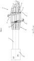
- a displacement tool 1 shown in fig. 1 comprises a tubular member 2 and a displacement means 3.
- the displacement means 3 is connected with the tubular member 2 in a rotationally fixed manner. That means, it is not possible that the displacement means 3 and the tubular member 2 rotate relative to each other.
- the displacement means 3 comprises a cylindrical portion 4 enclosing the tubular member 2.
- the tubular member 2 passes through the displacement means 3 and protrudes from the displacement means 3 in an axial direction A of the displacement tool 1.
- the displacement means 3 comprises a thread 5 that is only arranged on the cylindrical portion 4.
- the thread 5 can be a helical thread.
- the tubular member 2 is arranged coaxially with respect to the displacement means 3.
- a closure means 20 is attached to the end of the tubular member 2 that protrudes from the displacement means 3.
- a connection means 23 is arranged at another end of the tubular member 2.
- the connection means 23 is used to attach the displacement tool 1 to a machine 24 that is shown in figure 6 .
- the machine 24 applies a torque to the displacement tool 1 and can move the displacement tool 1 along the axial direction A so that the displacements tool 1 can dig a pile bore in a ground.
- the displacement means 3 comprises a conical portion 17 that is connected with the cylindrical portion 4.
- the conical portion 17 is connected with an end of the cylindrical portion 4.
- An end of the conical portion 17 offset from the cylindrical portion 4 is connected with the tubular member 2 in a rotationally fixed manner.
- the end of the conical portion 17 has a cross section, in particular diameter, smaller than the cross section, in particular diameter, of the conical portion 17 being connected with the cylindrical portion 4.
- the conical portion 17 is arranged such that the cross section, in particular diameter, increases from the end of the conical portion 17 along the axial direction A towards the connection means 23.
- the displacement means 3 comprises a further conical portion 18 that is connected with the cylindrical portion 4.
- the further conical portion 18 is connected with another end of the cylindrical portion 4.
- An end of the further conical portion 18 offset from the cylindrical portion 4 is connected with the tubular member 2 in a rotationally fixed manner.
- the end of the further conical portion 18 has a cross section, in particular diameter, smaller than the cross section, in particular diameter, of the further conical portion 18 being connected with the cylindrical portion 4.
- the further conical portion 18 is arranged such that the cross section, in particular diameter, decreases from the cylindrical portion 4 along the axial direction A towards the connection means 23.
- the cylindrical portion 4 is arranged between the conical portion 17 and the further conical portion 18 in axial direction A of the displacement tool 1.
- the conical portion 17, the cylindrical portion 4 and the further conical portion 4 are formed as one piece component.
- the displacement means 3 comprises protrusions 15 that are arranged on an upper face 16 of the thread 5.
- the protrusions 15 are arranged adjacent to each other along the extension of a thread line 14 shown in fig. 2 .
- the displacement means 3 comprises further protrusions 19.
- the further protrusions 19 are arranged on the conical portion 17, the cylindrical portion 4 and the further conical portion 18. They extend in axial direction A from the conical portion 17 towards the further conical portion 18.
- the further protrusions 19 arranged on the cylindrical portion 4 are interrupted in their extension by the helical thread 5.
- Two teeth 8 are arranged at an end 10 of the helical thread 5.
- the end 10 of the thread 5 is arranged proximal to the conical portion 17.
- the two teeth 8 are arranged adjacent to each other in a radial direction R of the displacement tool 1 as can be seen in fig. 4 .
- Two further teeth 9 are arranged at another end 11 of the helical thread 5.
- the other end 11 of the thread 5 is arranged proximal to the further conical portion 18.
- the two further teeth 9 are arranged adjacent to each other in the radial direction R of the displacement tool 1.
- the teeth 8 and further teeth 9 are arranged and orientated such that the teeth 8 move along a trajectories when the tubular member 2 is rotated in order to create the pile bore and that the further teeth 9 move along the same trajectories when the tubular member 2 is orientated in the opposite direction during the extraction of the displacement tool 1.
- the displacement tool 1 comprises two other teeth 22.
- the other teeth 22 are arranged on the end of the tubular member 2 that protrudes from the displacement means 3 in axial direction.
- the other teeth 22 are arranged adjacent to each other in a circumferential direction of the tubular member 22.
- Fig. 2 shows a side view of displacement tool 1 shown in fig. 1 .
- the thread 5 attached directly on the cylindrical portion 4 comprises one winding and extends from the end of the cylindrical portion 4 connected with the cylindrical portion 17 to the other end of the cylindrical portion 4 connected with the further conical portion 18.
- the tooth 8 and the further tooth 9 are identically shaped. Thus, in the following, only the structure of the tooth 8 is described.
- the tooth 8 has a tip 12 that lies on the thread line 14 of the helical thread 5.
- the tooth 8 is formed mirror symmetrically.
- the tooth 8 is symmetrically to a plane comprising the thread line 14.
- the further tooth 9 comprises a further tip 13 that lies on the thread line 14.
- Fig. 3 shows a cross section of the displacement means 3 shown in fig. 2 .
- the tubular member 2 comprises a hollow 21 that extends through the complete tubular member 3. Concrete is inserted via the hollow 21 in order to create the pile while the displacement tool 1 is retracted.
- the closure means 20 is positioned in an opened state so that concrete can be released by the tubular means 2 into the pile bore that is not shown in the figures.
- the closure means 20 is attached to the tubular member 2 and is transferred from the opened state to a closed state by rotation in the bore. In the closed state no concrete can be released by the displacement tool 1.
- the displacement means 3 has an interior through which the tubular member 2 passes.
- the cylindrical portion 4 has an outer diameter that is larger than an outer diameter of the tubular member 2. Additionally, an inner diameter of the cylindrical portion 4 is chosen such that there is a distance in radial direction between the cylindrical portion 4 and the tubular member 2.
- Fig. 4 shows a front view of the displacement tool 1 shown in fig. 1 and fig. 5 shows a rear view of the displacement tool 1 shown in fig. 1 .
- the other teeth 22 are diametrically arranged to each other with respect to the tubular member 2.
- the two teeth 8 arranged at the end 10 of the thread 5 are arranged adjacent to each other in radial direction R.
- the two further teeth 9 arranged at the other end 11 of the thread 5 are arranged adjacent to each other in radial direction R.
- Fig. 6 shows a machine 24 to which a displacement tool 1 as shown in fig. 1 to 5 is attached.
- the machine 24 comprises a drive unit 25.
- the drive unit 25 is adapted to rotate the non-shown displacement tool 1 and to move it in vertical direction that corresponds the axial direction A of the displacement tool 1. By moving the displacement tool 1 in vertical direction the pile bore is created or the displacement tool is retracted from the pile bore. The retraction direction is opposite to the drilling direction.
- the machine 24 also comprises a control unit 26 that controls the drive unit 25.
- the control unit 26 sends electric control signals to the drive unit 25 via non-shown wires in order to control the drive unit 25.
- the control unit 26 controls the drive unit 25 such that a ratio between an uplift speed of the displacement tool 1 and a rotational speed of the displacement tool is constant. The ratio depends on a thread pitch of the helical thread 5. During the uplift movement of the displacement means concrete can be inserted into the pile bore via the displacement tool 1.
Landscapes
- Engineering & Computer Science (AREA)
- Mining & Mineral Resources (AREA)
- Life Sciences & Earth Sciences (AREA)
- Structural Engineering (AREA)
- General Life Sciences & Earth Sciences (AREA)
- Geology (AREA)
- Paleontology (AREA)
- Civil Engineering (AREA)
- General Engineering & Computer Science (AREA)
- Fluid Mechanics (AREA)
- Environmental & Geological Engineering (AREA)
- Geochemistry & Mineralogy (AREA)
- Physics & Mathematics (AREA)
- Piles And Underground Anchors (AREA)
- Earth Drilling (AREA)
Description
- For making a concrete pile it is known to make use of a displacement tool. The displacement tool serves to dig a substantially cylindrical pile bore in the ground wherein the pile bore corresponds to the dimensions of the pile. In order to increase a load bearing capacity of the pile it is known to use a threaded displacement tool. The soil is displaced sideways during the insertion of the displacement tool. Such a displacement results in an improvement of the pile bearing condition. The pile is generated by inserting concrete through a hollow of the displacement tool while pulling out the tool form the pile bore.
EP 2 685 006 B1 - The German Utility Model No.
DE 20 2010 006 129 U1 discloses a device for inserting a standing pipe assembly into the soil with a drill head which is formed at the lower end of the pipe assembly. The drill head comprises a cylindrical part which is connected to a tapered part at the tip of the drill head and a tapered part at the top of the cylindrical part. A thread is arranged circumferentially around the entire length of the drill head including multiple windings around the cylindrical part. - UK Patent Application No.
GB 2556915 A - A disadvantage of the known displacement tool is that the friction between the displacement tool and the soil increases with increasing length of the thread. This leads to that a huge high weight machine has to be provided in order to apply the needed torque to the displacement tool. However, sometimes it is not possible or not wished to use such a machine for various reasons.
- The object of the invention is to provide an improved displacement tool.
- The object is solved by a displacement tool for displacing soil according to
claim 1 - The displacement tool comprises a tubular member and a displacement means connected to the tubular member in a rotationally fixed manner, wherein the displacement means comprises a cylindrical portion enclosing the tubular member, wherein the displacement means comprises a, in particular helical, thread that is only arranged on the cylindrical portion wherein the thread comprise at least one, in particular merely one, winding wherein.
- a. at least one tooth is arranged at an end of the thread and/or in that
- b. at least one further tooth is arranged at another end of the thread.
- The inventive subject-matter has the advantage that the friction between the thread and the soil is lower as the thread is only arranged at the cylindrical portion of the displacement tool. It has been recognized that it is not necessary to provide the thread over the complete length of the tubular member but only on cylindrical portion of the displacement means. Additionally, a high load bearing capacity of the pile is achieved in that the cylindrical portion encloses the tubular member and, thus, has a larger diameter than the tubular member. Such a displacement means enables the usage of a low-weight machine in order to dig pile bores. The cylindrical portion encloses the tubular member in circumferential direction of the tubular member. In particular, the cylindrical portion encloses the tubular member by 360° in circumferential direction of the tubular member.
- As the thread comprises merely one winding the friction between the displacement tool, in particular between the thread and the soil, is low. A winding of the thread is achieved by a rotation of the tubular means and, thus, the displacement means by 360°.
- Another advantage of the displacement tool is that the tooth and/or further tooth ensure easy cutting through the soil, hence reducing the friction between the displacement tool and the soil. The tooth and/or further tooth can be from a different material than the remaining part of the thread.
- According to an embodiment the thread can extend from one end of the cylindrical portion to another end of the cylindrical portion in axial direction of the cylindrical portion and/or the tubular means. Thus, a plane exists that comprises the end of the cylindrical portion and the thread. Additionally, another plane exists that comprises the other end of the cylindrical portion and the thread. The extension of the thread over the complete length of the cylindrical portion in axial direction has the advantage that the contact surface between the thread and the soil is low.
- However, as the thread has a long extension in axial direction of the cylindrical portion and/or tubular means a lot of soil can be displaced in radial direction with respect to the tubular means during one rotation of the tubular means. By using the displacement means for digging a vertical pile bore the radial direction corresponds with a horizontal direction. The thread can be welded to the cylindrical portion.
- The thread can comprise exactly two teeth arranged at the end of the thread and/or exactly two further teeth arranged at the other end of the helical thread. The teeth can be arranged adjacent to each other in radial direction of the tubular means and/or the displacement means. Additionally, the helical thread can comprise exactly two further teeth arranged at the other end of the thread wherein the further teeth are arranged adjacent to each other in radial direction of the tubular means and/or the displacement means. The provision of two teeth and/or two further teeth further simplifies the cutting through the soil. Additionally, it enables that the thread is longer in radial direction of the tubular means and/or the displacement means. A teeth having a long radial length leads to a pile with a high load bearing capacity.
- The tooth and the further tooth can be identically shaped. A tip of the tooth and a further tip of the further tooth are arranged such that they lie on a thread line of the thread. Such a formed tooth and/or further tooth can be achieved when the tooth and/or the further tooth are formed mirror symmetric. A mirror plane can comprise the thread line of the helical thread. The tooth and/or the further tooth can be shaped like an arrow. The tip of the tooth and/or the tip of the further tooth can be arranged offset to the remaining part of the thread.
- The tooth and the further tooth can be are arranged such that the tooth moves along a trajectory when the tubular member is rotated and that the further tooth moves along the same trajectory when the tubular member is rotated in an opposite direction. The provision of the further tooth ensures maintaining the clear groove of the pile bore in the soil. This is important as the groove of the pile bore contributes to load bearing capacity of the pile while saving concrete in the volume between the helical threads.
- Protrusions can be arranged on an upper face of the thread. The protrusions can extend from the upper face of the thread in radial direction and can be arranged adjacent to each other along the thread line of the thread. The provision of the protrusions has the advantage that the thread is protected from wear and tear during the operation of the displacement means.
- According to another embodiment of the invention the displacement means can comprise a conical portion that is connected with an end of the cylindrical portion and/or the displacement means can comprises a further conical portion that is connected with another end of the cylindrical portion. The conical portion can be arranged in an area of the displacement means proximal to an end of the tubular member that has the opening through which concrete can be released. The further conical portion can be arranged in an area of the displacement means distal to the end of the tubular means. The cylindrical portion can be arranged between the conical portion and the further conical portion in axial direction of the displacement means and/or the tubular member.
- The conical portion induces radial, in particular, horizontal forces in the soil. The cylindrical portion together with the thread arranged is used for the stabilization of the soil. The further conical portion is used for densification of any loose soil areas during extraction of the soil. The conical portion, the cylindrical portion and the further conical shaped portion can form a one piece displacement means.
- The conical portion and/or the further conical portion can be connected to the tubular member in a rotationally fixed manner. It is possible to connect the conical portion and/or the further conical portion via a weld connection with the tubular member. In particular, an end of the conical portion offset to the cylindrical portion and/or an end of the further conical portion offset to the cylindrical portion is connected to the tubular member in the rotationally fixed manner.
- The displacement means can comprise a plurality of further protrusions arranged adjacent to each other in a circumferential direction of the displacement means. The further protrusions protect the displacement means form tear and wear during its operation. The further protrusions can extend in axial direction of the displacement means from the conical portion and extend via the cylindrical portion to the further conical portion. The further protrusion extending in the cylindrical portion can be interrupted by the thread.
- The tubular member can pass through the displacement means. In particular, the tubular member can pass through the displacement means such that an end of the tubular member protrudes from the displacement means in axial direction.
- According to an embodiment of the invention the displacement tool can comprises a closure means that in a closed state closes a hollow of the tubular member and in an opened state releases the hollow of the tubular member. In the closed state of the closure means the concrete cannot flow out of the tubular member. In the opened state of the closure means the concrete cannot flow out of the tubular member. Such a closure means has the advantage that the closure means does not remain in the pile bore when the displacement means is retracted. This does not occur as the closure means is mechanically connected to the tubular member.
- The closure means can be built such that it rotates in order to change from the closed state to the opened state or vice versa. The closure means can be attached to the end of the tubular member.
- The displacement tool can comprise at least one other tooth that is arranged at the end of the tubular member. The tooth protects the closure means from being destroyed or damaged by loosening the soil when the displacement tool is drilled.
- According to an embodiment of the invention the cylindrical portion can be arranged coaxially to the tubular member and/or the cylindrical portion and the conical portion and/or the further conical portion can be arranged coaxially to each other.
- The displacement means can be built such that a ratio of an outer diameter of the cylindrical portion to an outer diameter of the tubular member is between 1,5 to 2,5, in particular 1,8 to 2,2. Additionally, the displacement tool can be built such that a ratio of an axial length of the cylindrical portion to the length of the conical portion and/or the further conical portion is between 1,5 to 2,5, in particular 1,8 to 2,2. The length of the conical portion can be longer in axial direction than the length of the conical portion and/or the further conical portion. Such a formed displacement tool has the advantage that a pile with a high load bearing capacity can be achieved wherein the torque to be applied is not such that huge weight machines have to be used.
- Of particular advantage is a machine comprising a displacement tool according to the invention. The machine comprises a drive unit for driving the displacement tool. The drive unit can rotate the displacement tool. Additionally, the drive unit can move the displacement tool along the axial direction of the displacement means.
- The machine comprises a control unit for controlling the drive unit. The control unit can control the rotational speed of the displacement tool. Additionally, the control unit can control a downlift speed of the displacement tool when it creates the pile bore and an uplift speed of the displacement tool when the pile bore is generated and concrete is inserted into the pile bore. For controlling the drive unit, the control unit can send electric control signals to the drive unit.
- According to an embodiment of the invention the control unit controls the drive unit such that a ratio between the uplift speed of the displacement tool and the rotational speed of the displacement tool corresponds with a predetermined value. The value does not change during the operation of the displacement tool and, thus, is constant. Keeping a constant ratio between the rotational speed and the uplift speed of the displacement tool enables that the concrete screw created in the pile bore has desired shape and strength properties. In particular, the control unit can automatically control the drive unit in order to keep the value constant during operation. In particular, the control unit keeps the ratio constant when the rotation speed and/or the uplift speed change during the operation. The control unit can control the drive unit such that e.g. the uplift speed is reduced when the rotation speed of the displacement tool is limited by soil resistance.
- The control unit can control the drive unit such that the drilling is made with maximum speed of the displacement tool when the pile bore is generated. In particular, the drive unit can be controlled such that the ratio between the rotational speed and the uplift speed is not constant during creation of the pile bore.
- The ratio depends on a thread pitch of the helical thread. If flight spacing is x [meter], then relation between uplift speed and rotation sped is equal to 1 [meter]/x[meter], eg. if the flight spacing is 0,25 m the displacement tool rotation speed combined with uplift speed is equal 1/0,25 = 4, which means that in order to achieve required pile shape it is necessary to get four rotations on each 1m of uplift.
- In the figures, the subject-matter of the invention is schematically shown, wherein identical or similarly acting elements are usually provided with the same reference signs. Here shows:
- Fig. 1
- shows a perspective view of the displacement tool according to an embodiment of the invention,
- Fig. 2
- shows a side view of the displacement tool shown in
fig. 1 , - Fig 3
- shows a cross section view of the displacement means shown in
fig. 2 , - Fig. 4
- shows a front view of the displacement tool shown in
fig. 1 , - Fig. 5
- shows a rear view of the displacement tool shown in
fig. 1 , - Fig. 6
- shows a machine to which a displacement tool as shown in
fig. 1 to 5 is attached. - A
displacement tool 1 shown infig. 1 comprises atubular member 2 and a displacement means 3. The displacement means 3 is connected with thetubular member 2 in a rotationally fixed manner. That means, it is not possible that the displacement means 3 and thetubular member 2 rotate relative to each other. The displacement means 3 comprises a cylindrical portion 4 enclosing thetubular member 2. In particular, thetubular member 2 passes through the displacement means 3 and protrudes from the displacement means 3 in an axial direction A of thedisplacement tool 1. The displacement means 3 comprises athread 5 that is only arranged on the cylindrical portion 4. Thethread 5 can be a helical thread. - The
tubular member 2 is arranged coaxially with respect to the displacement means 3. A closure means 20 is attached to the end of thetubular member 2 that protrudes from the displacement means 3. A connection means 23 is arranged at another end of thetubular member 2. The connection means 23 is used to attach thedisplacement tool 1 to amachine 24 that is shown infigure 6 . Themachine 24 applies a torque to thedisplacement tool 1 and can move thedisplacement tool 1 along the axial direction A so that thedisplacements tool 1 can dig a pile bore in a ground. - The displacement means 3 comprises a
conical portion 17 that is connected with the cylindrical portion 4. In particular, theconical portion 17 is connected with an end of the cylindrical portion 4. An end of theconical portion 17 offset from the cylindrical portion 4 is connected with thetubular member 2 in a rotationally fixed manner. The end of theconical portion 17 has a cross section, in particular diameter, smaller than the cross section, in particular diameter, of theconical portion 17 being connected with the cylindrical portion 4. Thus, theconical portion 17 is arranged such that the cross section, in particular diameter, increases from the end of theconical portion 17 along the axial direction A towards the connection means 23. - Additionally, the displacement means 3 comprises a further
conical portion 18 that is connected with the cylindrical portion 4. In particular, the furtherconical portion 18 is connected with another end of the cylindrical portion 4. An end of the furtherconical portion 18 offset from the cylindrical portion 4 is connected with thetubular member 2 in a rotationally fixed manner. The end of the furtherconical portion 18 has a cross section, in particular diameter, smaller than the cross section, in particular diameter, of the furtherconical portion 18 being connected with the cylindrical portion 4. Thus, the furtherconical portion 18 is arranged such that the cross section, in particular diameter, decreases from the cylindrical portion 4 along the axial direction A towards the connection means 23. - The cylindrical portion 4 is arranged between the
conical portion 17 and the furtherconical portion 18 in axial direction A of thedisplacement tool 1. Theconical portion 17, the cylindrical portion 4 and the further conical portion 4 are formed as one piece component. - The displacement means 3 comprises
protrusions 15 that are arranged on anupper face 16 of thethread 5. Theprotrusions 15 are arranged adjacent to each other along the extension of athread line 14 shown infig. 2 . Additionally, the displacement means 3 comprisesfurther protrusions 19. Thefurther protrusions 19 are arranged on theconical portion 17, the cylindrical portion 4 and the furtherconical portion 18. They extend in axial direction A from theconical portion 17 towards the furtherconical portion 18. Thefurther protrusions 19 arranged on the cylindrical portion 4 are interrupted in their extension by thehelical thread 5. - Two
teeth 8 are arranged at anend 10 of thehelical thread 5. Theend 10 of thethread 5 is arranged proximal to theconical portion 17. The twoteeth 8 are arranged adjacent to each other in a radial direction R of thedisplacement tool 1 as can be seen infig. 4 . Twofurther teeth 9 are arranged at anotherend 11 of thehelical thread 5. Theother end 11 of thethread 5 is arranged proximal to the furtherconical portion 18. The twofurther teeth 9 are arranged adjacent to each other in the radial direction R of thedisplacement tool 1. - The
teeth 8 andfurther teeth 9 are arranged and orientated such that theteeth 8 move along a trajectories when thetubular member 2 is rotated in order to create the pile bore and that thefurther teeth 9 move along the same trajectories when thetubular member 2 is orientated in the opposite direction during the extraction of thedisplacement tool 1. - The
displacement tool 1 comprises twoother teeth 22. Theother teeth 22 are arranged on the end of thetubular member 2 that protrudes from the displacement means 3 in axial direction. Theother teeth 22 are arranged adjacent to each other in a circumferential direction of thetubular member 22. -
Fig. 2 shows a side view ofdisplacement tool 1 shown infig. 1 . Thethread 5 attached directly on the cylindrical portion 4 comprises one winding and extends from the end of the cylindrical portion 4 connected with thecylindrical portion 17 to the other end of the cylindrical portion 4 connected with the furtherconical portion 18. - The
tooth 8 and thefurther tooth 9 are identically shaped. Thus, in the following, only the structure of thetooth 8 is described. Thetooth 8 has atip 12 that lies on thethread line 14 of thehelical thread 5. Thetooth 8 is formed mirror symmetrically. In particular, thetooth 8 is symmetrically to a plane comprising thethread line 14. Likewise, thefurther tooth 9 comprises afurther tip 13 that lies on thethread line 14. -
Fig. 3 shows a cross section of the displacement means 3 shown infig. 2 . Thetubular member 2 comprises a hollow 21 that extends through the completetubular member 3. Concrete is inserted via the hollow 21 in order to create the pile while thedisplacement tool 1 is retracted. The closure means 20 is positioned in an opened state so that concrete can be released by the tubular means 2 into the pile bore that is not shown in the figures. The closure means 20 is attached to thetubular member 2 and is transferred from the opened state to a closed state by rotation in the bore. In the closed state no concrete can be released by thedisplacement tool 1. - The displacement means 3 has an interior through which the
tubular member 2 passes. The cylindrical portion 4 has an outer diameter that is larger than an outer diameter of thetubular member 2. Additionally, an inner diameter of the cylindrical portion 4 is chosen such that there is a distance in radial direction between the cylindrical portion 4 and thetubular member 2. -
Fig. 4 shows a front view of thedisplacement tool 1 shown infig. 1 andfig. 5 shows a rear view of thedisplacement tool 1 shown infig. 1 . As is evident fromfig. 4 , theother teeth 22 are diametrically arranged to each other with respect to thetubular member 2. - The two
teeth 8 arranged at theend 10 of thethread 5 are arranged adjacent to each other in radial direction R. Likewise, the twofurther teeth 9 arranged at theother end 11 of thethread 5 are arranged adjacent to each other in radial direction R. -
Fig. 6 shows amachine 24 to which adisplacement tool 1 as shown infig. 1 to 5 is attached. Themachine 24 comprises adrive unit 25. Thedrive unit 25 is adapted to rotate thenon-shown displacement tool 1 and to move it in vertical direction that corresponds the axial direction A of thedisplacement tool 1. By moving thedisplacement tool 1 in vertical direction the pile bore is created or the displacement tool is retracted from the pile bore. The retraction direction is opposite to the drilling direction. Themachine 24 also comprises acontrol unit 26 that controls thedrive unit 25. In particular, thecontrol unit 26 sends electric control signals to thedrive unit 25 via non-shown wires in order to control thedrive unit 25. - The
control unit 26 controls thedrive unit 25 such that a ratio between an uplift speed of thedisplacement tool 1 and a rotational speed of the displacement tool is constant. The ratio depends on a thread pitch of thehelical thread 5. During the uplift movement of the displacement means concrete can be inserted into the pile bore via thedisplacement tool 1. -
- 1
- displacement tool
- 2
- tubular member
- 3
- displacement means
- 4
- cylindrical portion
- 5
- helical thread
- 8
- tooth
- 9
- further tooth
- 10
- end of helical thread
- 11
- other end of helical thread
- 12
- tip
- 13
- further tip
- 14
- thread line
- 15
- protrusion
- 16
- upper face
- 17
- conical portion
- 18
- further conical portion
- 19
- further protrusions
- 20
- closure means
- 21
- hollow
- 22
- other tooth
- 23
- connection means
- 24
- machine
- 25
- drive unit
- 26
- control unit
- A
- axial direction
- R
- radial direction
Claims (15)
- Displacement tool (1) for displacing soil, wherein the displacement tool (1) comprises:
a tubular member (2) and a displacement means (3) connected to the tubular member (2) in a rotationally fixed manner, wherein the displacement means (3) comprises a cylindrical portion (4) enclosing the tubular member (2), wherein:the displacement means (3) comprises a thread (5), whereinat least one tooth (8) is arranged at an end (10) of the thread (5); andat least one further tooth (9) is arranged at another end (11) of the thread (5), wherein:the thread (5) is only arranged on the cylindrical portion (4);the thread (5) comprises merely one winding; anda tip (12) of the tooth (8) and a further tip (13) of the further tooth (9) are arranged such that they lie on a thread line (14) of the thread (5). - Displacement tool (1) according to claim 1, wherein the thread (5) extends from one end of the cylindrical portion (4) to another end of the cylindrical portion (4) in axial direction (A).
- Displacement tool (1) according to claim 1 or 2, whereina. exactly two teeth (8) are arranged at the end (10) of the thread (5) and/or exactly two further teeth (9) arranged at the other end (11) of the thread (5) or in thatb. exactly two teeth (8) are arranged at the end (10) of the thread (5) wherein the teeth (8) are arranged adjacent to each other in radial direction (R) and/or in thatc. exactly two further teeth (9) are arranged at the other end (11) of the thread (5) wherein the further teeth (9) are arranged adjacent to each other in radial direction (R).
- Displacement tool (1) according to claim 1 or 2, whereina. the tooth (8) and the further tooth (9) are identically shaped and/or in thatb. the tooth (8) and/or the further tooth (9) is formed mirror symmetric and/or in thatc. the tooth (8) and the further tooth (9) are arranged such that the tooth (8) moves along a trajectory when the tubular member (2) is rotated and that the further tooth (9) moves along the same trajectory when the tubular member (2) is rotated in an opposite direction.
- Displacement tool (1) according to one of the claims 1 to 4, wherein protrusions (15) are arranged on an upper face (16) of the thread (5).
- Displacement tool (1) according to one of the claims 1 to 5, whereina. a conical portion (17) connected to the cylindrical portion (4) and a further conical portion (18) connected to the cylindrical portion (4) is connected to the tubular member (2) in a rotationally fixed manner; orb. an end of the conical portion (17) offset to the cylindrical portion (4) and/or an end of the further conical portion (18) offset to the cylindrical portion (4) is connected to the tubular member (2) in a rotationally fixed manner.
- Displacement tool (1) according to one of the claims 1 to 6, wherein the displacement means (3) comprises a plurality of further protrusions (19) arranged adjacent to each other in a circumferential direction of the displacement means (3) whereina. the further protrusions (19) extend in axial direction (A) from the conical portion (17) via the cylindrical portion (4) to the further conical portion (18) and/or whereinb. the further protrusions (19) extending in the cylindrical portion (4) are interrupted by the thread (5).
- Displacement tool (1) according to one of the claims 1 to 7, wherein the tubular member (2) passes through the displacement means (3).
- Displacement tool (1) according to one of the claims 1 to 8, wherein that the displacement tool (1) comprises a closure means (20) that in a closed state closes a hollow (21) of the tubular member (2) and in an opened state releases the hollow (21) of the tubular member (2).
- Displacement tool (1) according to claim 9, whereina. the closure means (20) rotates in order to change from the closed state to the opened state or vice versa and/orb. the closure means (20) is attached to an end of the tubular member (2).
- Displacement tool (1) according to one of the claims 1 to 10, wherein the displacement tool (1) comprises at least one other tooth (22) that is arranged at the end of the tubular member (2).
- Displacement tool (1) according to one of the claims 1 to 11, whereina. a ratio of an outer diameter of the cylindrical portion (4) to an outer diameter of the tubular member (2) is between 1,5 to 2,5.b. a ratio of an axial length of the cylindrical portion (4) to the length of the conical portion is between 1,5 to 2,5.
- Machine (24) for creating a pile bore comprising the displacement tool (1) according to one of the claims 1 to 12.
- Machine (24) according to claim 13, wherein the machine (24) comprises a drive unit (25) for driving the displacement tool (1) and a control unit (26) for controlling the drive unit (25) wherein the control unit (26) controls the drive unit (25) such that a ratio between an uplift speed of the displacement tool (1) and a displacement tool (1) rotational speed corresponds with a predetermined value.
- Machine (24) according to claim 14, wherein the ratio depends on a thread pitch of the thread (5).
Applications Claiming Priority (1)
| Application Number | Priority Date | Filing Date | Title |
|---|---|---|---|
| LU102150A LU102150B1 (en) | 2020-10-21 | 2020-10-21 | Displacement tool for displacing soil |
Publications (3)
| Publication Number | Publication Date |
|---|---|
| EP3988716A1 EP3988716A1 (en) | 2022-04-27 |
| EP3988716C0 EP3988716C0 (en) | 2024-12-25 |
| EP3988716B1 true EP3988716B1 (en) | 2024-12-25 |
Family
ID=74175906
Family Applications (1)
| Application Number | Title | Priority Date | Filing Date |
|---|---|---|---|
| EP21203715.4A Active EP3988716B1 (en) | 2020-10-21 | 2021-10-20 | Displacement tool for displacing soil |
Country Status (2)
| Country | Link |
|---|---|
| EP (1) | EP3988716B1 (en) |
| LU (1) | LU102150B1 (en) |
Family Cites Families (6)
| Publication number | Priority date | Publication date | Assignee | Title |
|---|---|---|---|---|
| WO2000022244A1 (en) * | 1998-10-08 | 2000-04-20 | Vibro-Pile (Aust.) Pty. Ltd. | Auger |
| US20080131211A1 (en) * | 2004-07-13 | 2008-06-05 | Nesmith Willie M | Installation effort deep foudnation method |
| IT1394002B1 (en) * | 2009-04-21 | 2012-05-17 | Soilmec Spa | EXCAVATION AND CONSTIPATION EQUIPMENT FOR BUILDING SCREW POLES. |
| DE202010006129U1 (en) * | 2010-04-28 | 2010-08-05 | Kober, Herbert | Device for introducing a vertical pipe arrangement into the soil |
| GB2503918B (en) | 2012-07-12 | 2015-12-30 | Soletanche Freyssinet | Cutting head with a retractable threading tooth actuated by a rack/gear system |
| GB2556915B (en) * | 2016-11-25 | 2019-10-30 | Roger Bullivant Ltd | Apparatus, system and method for use in displacement boring for forming a pile |
-
2020
- 2020-10-21 LU LU102150A patent/LU102150B1/en active IP Right Grant
-
2021
- 2021-10-20 EP EP21203715.4A patent/EP3988716B1/en active Active
Also Published As
| Publication number | Publication date |
|---|---|
| EP3988716C0 (en) | 2024-12-25 |
| LU102150B1 (en) | 2022-04-22 |
| EP3988716A1 (en) | 2022-04-27 |
Similar Documents
| Publication | Publication Date | Title |
|---|---|---|
| EP2085566B1 (en) | Drilling assembly | |
| CA2012933C (en) | Directional rod pusher | |
| DE19607365C5 (en) | Method for steering an earth drilling device and a steerable device for producing an earth drilling | |
| CN101063399B (en) | Drilling implement for erecting a drilling pillar in the ground and method thereof | |
| US9133595B2 (en) | Bent blade screw ground anchor | |
| EP2770156B1 (en) | Drilling tool and method for drilling in soil | |
| EP2398968B1 (en) | Jet grouting equipment | |
| WO2009146895A2 (en) | Drill head | |
| DE2734185A1 (en) | PROCESS AND SYSTEM FOR DRILLING A PIPED DEEP DRILLING FOR THE PRODUCTION OF PIPED PILE FOUNDATIONS | |
| EP3877624B1 (en) | Kelly bar assembly for a drill and method for working soil | |
| DE60006276T2 (en) | DRILL HEAD WITH Eccentric Body | |
| LU102150B1 (en) | Displacement tool for displacing soil | |
| EP0806543B1 (en) | Drilling apparatus for percussive drilling | |
| CA1173427A (en) | Tool for formation of holes in macroporous compressible soils | |
| DE2933597C2 (en) | ||
| HK1040538A1 (en) | Excavation apparatus for forming piles in the ground | |
| EP0979920B1 (en) | Drill apparatus with twin impact system | |
| CN202989913U (en) | Pointless spiral pile | |
| WO2020078623A1 (en) | Method and device for dismantling geothermal probes | |
| DE3027990C2 (en) | ||
| US4438821A (en) | Mining machinery | |
| WO1994009244A1 (en) | Underreamer | |
| EP3662131A2 (en) | An apparatus and method for milling a window in a borehole | |
| EP2383419B1 (en) | Device for inserting a standing pipe assembly into the soil | |
| DE102011087096B4 (en) | Tool and method for creating boreholes with a non-rotationally symmetrical cross section |
Legal Events
| Date | Code | Title | Description |
|---|---|---|---|
| PUAI | Public reference made under article 153(3) epc to a published international application that has entered the european phase |
Free format text: ORIGINAL CODE: 0009012 |
|
| STAA | Information on the status of an ep patent application or granted ep patent |
Free format text: STATUS: THE APPLICATION HAS BEEN PUBLISHED |
|
| AK | Designated contracting states |
Kind code of ref document: A1 Designated state(s): AL AT BE BG CH CY CZ DE DK EE ES FI FR GB GR HR HU IE IS IT LI LT LU LV MC MK MT NL NO PL PT RO RS SE SI SK SM TR |
|
| STAA | Information on the status of an ep patent application or granted ep patent |
Free format text: STATUS: REQUEST FOR EXAMINATION WAS MADE |
|
| 17P | Request for examination filed |
Effective date: 20221027 |
|
| RBV | Designated contracting states (corrected) |
Designated state(s): AL AT BE BG CH CY CZ DE DK EE ES FI FR GB GR HR HU IE IS IT LI LT LU LV MC MK MT NL NO PL PT RO RS SE SI SK SM TR |
|
| STAA | Information on the status of an ep patent application or granted ep patent |
Free format text: STATUS: EXAMINATION IS IN PROGRESS |
|
| 17Q | First examination report despatched |
Effective date: 20230306 |
|
| GRAP | Despatch of communication of intention to grant a patent |
Free format text: ORIGINAL CODE: EPIDOSNIGR1 |
|
| STAA | Information on the status of an ep patent application or granted ep patent |
Free format text: STATUS: GRANT OF PATENT IS INTENDED |
|
| INTG | Intention to grant announced |
Effective date: 20240307 |
|
| GRAJ | Information related to disapproval of communication of intention to grant by the applicant or resumption of examination proceedings by the epo deleted |
Free format text: ORIGINAL CODE: EPIDOSDIGR1 |
|
| STAA | Information on the status of an ep patent application or granted ep patent |
Free format text: STATUS: EXAMINATION IS IN PROGRESS |
|
| GRAP | Despatch of communication of intention to grant a patent |
Free format text: ORIGINAL CODE: EPIDOSNIGR1 |
|
| STAA | Information on the status of an ep patent application or granted ep patent |
Free format text: STATUS: GRANT OF PATENT IS INTENDED |
|
| INTC | Intention to grant announced (deleted) | ||
| INTG | Intention to grant announced |
Effective date: 20240731 |
|
| GRAS | Grant fee paid |
Free format text: ORIGINAL CODE: EPIDOSNIGR3 |
|
| GRAA | (expected) grant |
Free format text: ORIGINAL CODE: 0009210 |
|
| STAA | Information on the status of an ep patent application or granted ep patent |
Free format text: STATUS: THE PATENT HAS BEEN GRANTED |
|
| AK | Designated contracting states |
Kind code of ref document: B1 Designated state(s): AL AT BE BG CH CY CZ DE DK EE ES FI FR GB GR HR HU IE IS IT LI LT LU LV MC MK MT NL NO PL PT RO RS SE SI SK SM TR |
|
| REG | Reference to a national code |
Ref country code: GB Ref legal event code: FG4D |
|
| REG | Reference to a national code |
Ref country code: CH Ref legal event code: EP |
|
| REG | Reference to a national code |
Ref country code: DE Ref legal event code: R096 Ref document number: 602021023818 Country of ref document: DE |
|
| REG | Reference to a national code |
Ref country code: IE Ref legal event code: FG4D |
|
| U01 | Request for unitary effect filed |
Effective date: 20250121 |
|
| U07 | Unitary effect registered |
Designated state(s): AT BE BG DE DK EE FI FR IT LT LU LV MT NL PT RO SE SI Effective date: 20250127 |
|
| PG25 | Lapsed in a contracting state [announced via postgrant information from national office to epo] |
Ref country code: HR Free format text: LAPSE BECAUSE OF FAILURE TO SUBMIT A TRANSLATION OF THE DESCRIPTION OR TO PAY THE FEE WITHIN THE PRESCRIBED TIME-LIMIT Effective date: 20241225 |
|
| PG25 | Lapsed in a contracting state [announced via postgrant information from national office to epo] |
Ref country code: NO Free format text: LAPSE BECAUSE OF FAILURE TO SUBMIT A TRANSLATION OF THE DESCRIPTION OR TO PAY THE FEE WITHIN THE PRESCRIBED TIME-LIMIT Effective date: 20250325 |
|
| PG25 | Lapsed in a contracting state [announced via postgrant information from national office to epo] |
Ref country code: GR Free format text: LAPSE BECAUSE OF FAILURE TO SUBMIT A TRANSLATION OF THE DESCRIPTION OR TO PAY THE FEE WITHIN THE PRESCRIBED TIME-LIMIT Effective date: 20250326 |
|
| PG25 | Lapsed in a contracting state [announced via postgrant information from national office to epo] |
Ref country code: RS Free format text: LAPSE BECAUSE OF FAILURE TO SUBMIT A TRANSLATION OF THE DESCRIPTION OR TO PAY THE FEE WITHIN THE PRESCRIBED TIME-LIMIT Effective date: 20250325 |
|
| PG25 | Lapsed in a contracting state [announced via postgrant information from national office to epo] |
Ref country code: SM Free format text: LAPSE BECAUSE OF FAILURE TO SUBMIT A TRANSLATION OF THE DESCRIPTION OR TO PAY THE FEE WITHIN THE PRESCRIBED TIME-LIMIT Effective date: 20241225 |
|
| PG25 | Lapsed in a contracting state [announced via postgrant information from national office to epo] |
Ref country code: PL Free format text: LAPSE BECAUSE OF FAILURE TO SUBMIT A TRANSLATION OF THE DESCRIPTION OR TO PAY THE FEE WITHIN THE PRESCRIBED TIME-LIMIT Effective date: 20241225 |
|
| PG25 | Lapsed in a contracting state [announced via postgrant information from national office to epo] |
Ref country code: ES Free format text: LAPSE BECAUSE OF FAILURE TO SUBMIT A TRANSLATION OF THE DESCRIPTION OR TO PAY THE FEE WITHIN THE PRESCRIBED TIME-LIMIT Effective date: 20241225 |
|
| PG25 | Lapsed in a contracting state [announced via postgrant information from national office to epo] |
Ref country code: IS Free format text: LAPSE BECAUSE OF FAILURE TO SUBMIT A TRANSLATION OF THE DESCRIPTION OR TO PAY THE FEE WITHIN THE PRESCRIBED TIME-LIMIT Effective date: 20250425 |
|
| PG25 | Lapsed in a contracting state [announced via postgrant information from national office to epo] |
Ref country code: SK Free format text: LAPSE BECAUSE OF FAILURE TO SUBMIT A TRANSLATION OF THE DESCRIPTION OR TO PAY THE FEE WITHIN THE PRESCRIBED TIME-LIMIT Effective date: 20241225 |
|
| PG25 | Lapsed in a contracting state [announced via postgrant information from national office to epo] |
Ref country code: CZ Free format text: LAPSE BECAUSE OF FAILURE TO SUBMIT A TRANSLATION OF THE DESCRIPTION OR TO PAY THE FEE WITHIN THE PRESCRIBED TIME-LIMIT Effective date: 20241225 |
|
| PLBE | No opposition filed within time limit |
Free format text: ORIGINAL CODE: 0009261 |
|
| STAA | Information on the status of an ep patent application or granted ep patent |
Free format text: STATUS: NO OPPOSITION FILED WITHIN TIME LIMIT |
|
| U20 | Renewal fee for the european patent with unitary effect paid |
Year of fee payment: 5 Effective date: 20251014 |
|
| 26N | No opposition filed |
Effective date: 20250926 |