EP3988627A2 - Battery pack - Google Patents
Battery pack Download PDFInfo
- Publication number
- EP3988627A2 EP3988627A2 EP20825551.3A EP20825551A EP3988627A2 EP 3988627 A2 EP3988627 A2 EP 3988627A2 EP 20825551 A EP20825551 A EP 20825551A EP 3988627 A2 EP3988627 A2 EP 3988627A2
- Authority
- EP
- European Patent Office
- Prior art keywords
- double
- sided adhesive
- adhesive film
- battery pack
- cut lines
- Prior art date
- Legal status (The legal status is an assumption and is not a legal conclusion. Google has not performed a legal analysis and makes no representation as to the accuracy of the status listed.)
- Pending
Links
Images



Classifications
-
- H—ELECTRICITY
- H01—ELECTRIC ELEMENTS
- H01M—PROCESSES OR MEANS, e.g. BATTERIES, FOR THE DIRECT CONVERSION OF CHEMICAL ENERGY INTO ELECTRICAL ENERGY
- H01M50/00—Constructional details or processes of manufacture of the non-active parts of electrochemical cells other than fuel cells, e.g. hybrid cells
- H01M50/20—Mountings; Secondary casings or frames; Racks, modules or packs; Suspension devices; Shock absorbers; Transport or carrying devices; Holders
-
- H—ELECTRICITY
- H01—ELECTRIC ELEMENTS
- H01M—PROCESSES OR MEANS, e.g. BATTERIES, FOR THE DIRECT CONVERSION OF CHEMICAL ENERGY INTO ELECTRICAL ENERGY
- H01M50/00—Constructional details or processes of manufacture of the non-active parts of electrochemical cells other than fuel cells, e.g. hybrid cells
- H01M50/20—Mountings; Secondary casings or frames; Racks, modules or packs; Suspension devices; Shock absorbers; Transport or carrying devices; Holders
- H01M50/233—Mountings; Secondary casings or frames; Racks, modules or packs; Suspension devices; Shock absorbers; Transport or carrying devices; Holders characterised by physical properties of casings or racks, e.g. dimensions
- H01M50/24—Mountings; Secondary casings or frames; Racks, modules or packs; Suspension devices; Shock absorbers; Transport or carrying devices; Holders characterised by physical properties of casings or racks, e.g. dimensions adapted for protecting batteries from their environment, e.g. from corrosion
-
- C—CHEMISTRY; METALLURGY
- C09—DYES; PAINTS; POLISHES; NATURAL RESINS; ADHESIVES; COMPOSITIONS NOT OTHERWISE PROVIDED FOR; APPLICATIONS OF MATERIALS NOT OTHERWISE PROVIDED FOR
- C09J—ADHESIVES; NON-MECHANICAL ASPECTS OF ADHESIVE PROCESSES IN GENERAL; ADHESIVE PROCESSES NOT PROVIDED FOR ELSEWHERE; USE OF MATERIALS AS ADHESIVES
- C09J7/00—Adhesives in the form of films or foils
- C09J7/20—Adhesives in the form of films or foils characterised by their carriers
-
- H—ELECTRICITY
- H01—ELECTRIC ELEMENTS
- H01M—PROCESSES OR MEANS, e.g. BATTERIES, FOR THE DIRECT CONVERSION OF CHEMICAL ENERGY INTO ELECTRICAL ENERGY
- H01M50/00—Constructional details or processes of manufacture of the non-active parts of electrochemical cells other than fuel cells, e.g. hybrid cells
- H01M50/20—Mountings; Secondary casings or frames; Racks, modules or packs; Suspension devices; Shock absorbers; Transport or carrying devices; Holders
- H01M50/204—Racks, modules or packs for multiple batteries or multiple cells
-
- H—ELECTRICITY
- H01—ELECTRIC ELEMENTS
- H01M—PROCESSES OR MEANS, e.g. BATTERIES, FOR THE DIRECT CONVERSION OF CHEMICAL ENERGY INTO ELECTRICAL ENERGY
- H01M50/00—Constructional details or processes of manufacture of the non-active parts of electrochemical cells other than fuel cells, e.g. hybrid cells
- H01M50/20—Mountings; Secondary casings or frames; Racks, modules or packs; Suspension devices; Shock absorbers; Transport or carrying devices; Holders
- H01M50/204—Racks, modules or packs for multiple batteries or multiple cells
- H01M50/207—Racks, modules or packs for multiple batteries or multiple cells characterised by their shape
- H01M50/209—Racks, modules or packs for multiple batteries or multiple cells characterised by their shape adapted for prismatic or rectangular cells
-
- H—ELECTRICITY
- H01—ELECTRIC ELEMENTS
- H01M—PROCESSES OR MEANS, e.g. BATTERIES, FOR THE DIRECT CONVERSION OF CHEMICAL ENERGY INTO ELECTRICAL ENERGY
- H01M50/00—Constructional details or processes of manufacture of the non-active parts of electrochemical cells other than fuel cells, e.g. hybrid cells
- H01M50/20—Mountings; Secondary casings or frames; Racks, modules or packs; Suspension devices; Shock absorbers; Transport or carrying devices; Holders
- H01M50/244—Secondary casings; Racks; Suspension devices; Carrying devices; Holders characterised by their mounting method
-
- H—ELECTRICITY
- H01—ELECTRIC ELEMENTS
- H01M—PROCESSES OR MEANS, e.g. BATTERIES, FOR THE DIRECT CONVERSION OF CHEMICAL ENERGY INTO ELECTRICAL ENERGY
- H01M50/00—Constructional details or processes of manufacture of the non-active parts of electrochemical cells other than fuel cells, e.g. hybrid cells
- H01M50/20—Mountings; Secondary casings or frames; Racks, modules or packs; Suspension devices; Shock absorbers; Transport or carrying devices; Holders
- H01M50/247—Mountings; Secondary casings or frames; Racks, modules or packs; Suspension devices; Shock absorbers; Transport or carrying devices; Holders specially adapted for portable devices, e.g. mobile phones, computers, hand tools or pacemakers
-
- H—ELECTRICITY
- H01—ELECTRIC ELEMENTS
- H01M—PROCESSES OR MEANS, e.g. BATTERIES, FOR THE DIRECT CONVERSION OF CHEMICAL ENERGY INTO ELECTRICAL ENERGY
- H01M50/00—Constructional details or processes of manufacture of the non-active parts of electrochemical cells other than fuel cells, e.g. hybrid cells
- H01M50/20—Mountings; Secondary casings or frames; Racks, modules or packs; Suspension devices; Shock absorbers; Transport or carrying devices; Holders
- H01M50/249—Mountings; Secondary casings or frames; Racks, modules or packs; Suspension devices; Shock absorbers; Transport or carrying devices; Holders specially adapted for aircraft or vehicles, e.g. cars or trains
-
- H—ELECTRICITY
- H01—ELECTRIC ELEMENTS
- H01M—PROCESSES OR MEANS, e.g. BATTERIES, FOR THE DIRECT CONVERSION OF CHEMICAL ENERGY INTO ELECTRICAL ENERGY
- H01M50/00—Constructional details or processes of manufacture of the non-active parts of electrochemical cells other than fuel cells, e.g. hybrid cells
- H01M50/20—Mountings; Secondary casings or frames; Racks, modules or packs; Suspension devices; Shock absorbers; Transport or carrying devices; Holders
- H01M50/262—Mountings; Secondary casings or frames; Racks, modules or packs; Suspension devices; Shock absorbers; Transport or carrying devices; Holders with fastening means, e.g. locks
- H01M50/264—Mountings; Secondary casings or frames; Racks, modules or packs; Suspension devices; Shock absorbers; Transport or carrying devices; Holders with fastening means, e.g. locks for cells or batteries, e.g. straps, tie rods or peripheral frames
-
- H—ELECTRICITY
- H01—ELECTRIC ELEMENTS
- H01M—PROCESSES OR MEANS, e.g. BATTERIES, FOR THE DIRECT CONVERSION OF CHEMICAL ENERGY INTO ELECTRICAL ENERGY
- H01M50/00—Constructional details or processes of manufacture of the non-active parts of electrochemical cells other than fuel cells, e.g. hybrid cells
- H01M50/20—Mountings; Secondary casings or frames; Racks, modules or packs; Suspension devices; Shock absorbers; Transport or carrying devices; Holders
- H01M50/289—Mountings; Secondary casings or frames; Racks, modules or packs; Suspension devices; Shock absorbers; Transport or carrying devices; Holders characterised by spacing elements or positioning means within frames, racks or packs
- H01M50/293—Mountings; Secondary casings or frames; Racks, modules or packs; Suspension devices; Shock absorbers; Transport or carrying devices; Holders characterised by spacing elements or positioning means within frames, racks or packs characterised by the material
-
- H—ELECTRICITY
- H01—ELECTRIC ELEMENTS
- H01M—PROCESSES OR MEANS, e.g. BATTERIES, FOR THE DIRECT CONVERSION OF CHEMICAL ENERGY INTO ELECTRICAL ENERGY
- H01M50/00—Constructional details or processes of manufacture of the non-active parts of electrochemical cells other than fuel cells, e.g. hybrid cells
- H01M50/50—Current conducting connections for cells or batteries
- H01M50/572—Means for preventing undesired use or discharge
- H01M50/584—Means for preventing undesired use or discharge for preventing incorrect connections inside or outside the batteries
- H01M50/588—Means for preventing undesired use or discharge for preventing incorrect connections inside or outside the batteries outside the batteries, e.g. incorrect connections of terminals or busbars
-
- H—ELECTRICITY
- H01—ELECTRIC ELEMENTS
- H01M—PROCESSES OR MEANS, e.g. BATTERIES, FOR THE DIRECT CONVERSION OF CHEMICAL ENERGY INTO ELECTRICAL ENERGY
- H01M50/00—Constructional details or processes of manufacture of the non-active parts of electrochemical cells other than fuel cells, e.g. hybrid cells
- H01M50/50—Current conducting connections for cells or batteries
- H01M50/572—Means for preventing undesired use or discharge
- H01M50/584—Means for preventing undesired use or discharge for preventing incorrect connections inside or outside the batteries
- H01M50/59—Means for preventing undesired use or discharge for preventing incorrect connections inside or outside the batteries characterised by the protection means
- H01M50/593—Spacers; Insulating plates
-
- H—ELECTRICITY
- H01—ELECTRIC ELEMENTS
- H01M—PROCESSES OR MEANS, e.g. BATTERIES, FOR THE DIRECT CONVERSION OF CHEMICAL ENERGY INTO ELECTRICAL ENERGY
- H01M50/00—Constructional details or processes of manufacture of the non-active parts of electrochemical cells other than fuel cells, e.g. hybrid cells
- H01M50/50—Current conducting connections for cells or batteries
- H01M50/572—Means for preventing undesired use or discharge
- H01M50/584—Means for preventing undesired use or discharge for preventing incorrect connections inside or outside the batteries
- H01M50/59—Means for preventing undesired use or discharge for preventing incorrect connections inside or outside the batteries characterised by the protection means
- H01M50/595—Tapes
-
- C—CHEMISTRY; METALLURGY
- C09—DYES; PAINTS; POLISHES; NATURAL RESINS; ADHESIVES; COMPOSITIONS NOT OTHERWISE PROVIDED FOR; APPLICATIONS OF MATERIALS NOT OTHERWISE PROVIDED FOR
- C09J—ADHESIVES; NON-MECHANICAL ASPECTS OF ADHESIVE PROCESSES IN GENERAL; ADHESIVE PROCESSES NOT PROVIDED FOR ELSEWHERE; USE OF MATERIALS AS ADHESIVES
- C09J2203/00—Applications of adhesives in processes or use of adhesives in the form of films or foils
- C09J2203/33—Applications of adhesives in processes or use of adhesives in the form of films or foils for batteries or fuel cells
-
- C—CHEMISTRY; METALLURGY
- C09—DYES; PAINTS; POLISHES; NATURAL RESINS; ADHESIVES; COMPOSITIONS NOT OTHERWISE PROVIDED FOR; APPLICATIONS OF MATERIALS NOT OTHERWISE PROVIDED FOR
- C09J—ADHESIVES; NON-MECHANICAL ASPECTS OF ADHESIVE PROCESSES IN GENERAL; ADHESIVE PROCESSES NOT PROVIDED FOR ELSEWHERE; USE OF MATERIALS AS ADHESIVES
- C09J2301/00—Additional features of adhesives in the form of films or foils
- C09J2301/10—Additional features of adhesives in the form of films or foils characterized by the structural features of the adhesive tape or sheet
- C09J2301/12—Additional features of adhesives in the form of films or foils characterized by the structural features of the adhesive tape or sheet by the arrangement of layers
- C09J2301/124—Additional features of adhesives in the form of films or foils characterized by the structural features of the adhesive tape or sheet by the arrangement of layers the adhesive layer being present on both sides of the carrier, e.g. double-sided adhesive tape
-
- C—CHEMISTRY; METALLURGY
- C09—DYES; PAINTS; POLISHES; NATURAL RESINS; ADHESIVES; COMPOSITIONS NOT OTHERWISE PROVIDED FOR; APPLICATIONS OF MATERIALS NOT OTHERWISE PROVIDED FOR
- C09J—ADHESIVES; NON-MECHANICAL ASPECTS OF ADHESIVE PROCESSES IN GENERAL; ADHESIVE PROCESSES NOT PROVIDED FOR ELSEWHERE; USE OF MATERIALS AS ADHESIVES
- C09J2301/00—Additional features of adhesives in the form of films or foils
- C09J2301/20—Additional features of adhesives in the form of films or foils characterized by the structural features of the adhesive itself
- C09J2301/204—Additional features of adhesives in the form of films or foils characterized by the structural features of the adhesive itself the adhesive coating being discontinuous
-
- C—CHEMISTRY; METALLURGY
- C09—DYES; PAINTS; POLISHES; NATURAL RESINS; ADHESIVES; COMPOSITIONS NOT OTHERWISE PROVIDED FOR; APPLICATIONS OF MATERIALS NOT OTHERWISE PROVIDED FOR
- C09J—ADHESIVES; NON-MECHANICAL ASPECTS OF ADHESIVE PROCESSES IN GENERAL; ADHESIVE PROCESSES NOT PROVIDED FOR ELSEWHERE; USE OF MATERIALS AS ADHESIVES
- C09J2400/00—Presence of inorganic and organic materials
- C09J2400/10—Presence of inorganic materials
- C09J2400/12—Ceramic
- C09J2400/123—Ceramic in the substrate
-
- Y—GENERAL TAGGING OF NEW TECHNOLOGICAL DEVELOPMENTS; GENERAL TAGGING OF CROSS-SECTIONAL TECHNOLOGIES SPANNING OVER SEVERAL SECTIONS OF THE IPC; TECHNICAL SUBJECTS COVERED BY FORMER USPC CROSS-REFERENCE ART COLLECTIONS [XRACs] AND DIGESTS
- Y02—TECHNOLOGIES OR APPLICATIONS FOR MITIGATION OR ADAPTATION AGAINST CLIMATE CHANGE
- Y02E—REDUCTION OF GREENHOUSE GAS [GHG] EMISSIONS, RELATED TO ENERGY GENERATION, TRANSMISSION OR DISTRIBUTION
- Y02E60/00—Enabling technologies; Technologies with a potential or indirect contribution to GHG emissions mitigation
- Y02E60/10—Energy storage using batteries
Definitions
- the present disclosure relates to a battery pack.
- a secondary battery is a battery that can be charged and discharged, unlike a primary battery that cannot be charged.
- Secondary batteries are used as energy sources for mobile devices, electric vehicles, hybrid vehicles, electric bicycles, uninterruptible power supply, and the like.
- the secondary batteries may be used in the form of a single battery depending on the type of external device to be applied, or may be used in the form of a module in which a plurality of batteries are connected and bundled as a unit.
- Small mobile appliances such as cell phones can be operated for a certain period of time with the power and capacity of a single battery.
- a module type battery including a plurality of batteries is preferred, and an output voltage or an output current can be increased according to the number of built-in batteries.
- An embodiment of the present disclosure provides a battery pack having improved driving stability and advantageous in light reduction.
- An embodiment of the present disclosure provides a battery pack in which the structure of an insulating adhesive tape interposed between adjacent battery cells is improved, thereby preventing defects caused when the insulating adhesive tape is cut or attached.
- a battery back of the present disclosure includes
- a battery pack in which adjacent battery cells are insulated from each other and structurally bonded to each other, thereby improving driving stability and enabling weigh reduction, and can be provided a battery pack in which cutting defects caused in the process of individually cutting a continuously supplied insulating adhesive tape can be prevented, a work for attaching the insulating adhesive tape can be easily performed by preventing the crumples or wrinkles of the insulating adhesive tape, and adhesion force between battery cells can be maintained firmly.
- a battery back of the present disclosure includes
- the cut lines may be formed on a straight line extending obliquely along an oblique direction with respect to a width direction of the double-sided adhesive film.
- the cut lines may extend at a constant inclination angle with respect to a width direction of the double-sided adhesive film.
- the cut lines may be formed at a regular pitch interval along a length direction of the double-sided adhesive film.
- the pitch interval may be set in a range of 20 mm to 30 mm.
- a shortest distance between the cut lines adjacent to each other in a length direction of the double-sided adhesive film may have a value greater than at least 0.
- the shortest distance between the cut lines adjacent to each other may be set in a range of 10 mm to 15 mm.
- the cut line may include first and second ends opposite to each other along a width direction of the double-sided adhesive film, and the shortest distance between the cut lines adjacent to each other may correspond to a distance between the first and second ends opposite to each other.
- the cut lines may be formed at a regular pitch interval along the length direction of the double-sided adhesive film, and the shortest distance between the cut lines adjacent to each other may be formed to be a half of the pitch interval.
- the cut line may include first and second ends opposite to each other along a width direction of the double-sided adhesive film, and the pitch interval may correspond to a distance between the same first ends or second ends of the cut lines adjacent to each other.
- the cut line may be limitedly formed over a cut thickness corresponding to a part of a total thickness of the double-sided adhesive film.
- an attachment area of the double-sided adhesive film attached to the insulating film may be smaller than an area of the insulating film.
- the double-sided adhesive film may be formed in a stripe pattern extending along one direction crossing the insulating film.
- the double-sided adhesive film may extend along a height direction of the battery cell.
- the double-sided adhesive film may be formed in pairs spaced apart from each other along a width direction of the battery cell.
- the double-sided adhesive film may be attached to front and back surfaces of the insulating film, respectively.
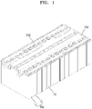
- FIG. 1 shows a perspective view of a battery pack according to an embodiment of the present disclosure.
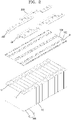
- FIG. 2 shows an exploded perspective view of the battery pack shown in FIG. 1 .
- the battery pack may include a plurality of battery cells C, a bus bar 200 for electrically connecting the plurality of battery cells C, and a bus bar holder 150 for providing electrical insulation between the bus bar 200 and the battery cells C.
- the battery cell (C) may include an electrode assembly (not shown) and a case 10 for accommodating the electrode assembly (not shown), and first and second electrode terminals 11 and 12 electrically connected to different electrode plates of an electrode assembly (not shown) may be formed on the case 10.
- the first and second electrode terminals 11 and 12 may be assembled on the case 10, and any one of the first and second electrode terminals 11 and 12, for example, the first electrode terminal 11 may form a conductive connection with the case 10 and may have the same polarity as the case 10. In this case, the first electrode terminal 11 may be omitted, and the case 10 may serve as the first electrode terminal 11. Meanwhile, the second electrode terminal 12 may form an insulating connection with the case 10.
- the bus bar 200 may connect a pair of adjacent battery cells C in parallel with the same polarity, and may connect a pair of adjacent battery cells C in parallel with each other to form a parallel module PM.
- the bus bar 200 may connect a pair of parallelly connected battery cells C (parallel module PM) and another pair of parallelly connected battery cells C (another parallel module PM) in series with opposite polarities.
- the bus bar 200 may electrically connect a pair of parallelly connected battery cells C (parallel module PM) and another pair of parallelly connected battery cells C (another parallel module PM) in series, but a pair of battery cells C (parallel module PM) and another pair of battery cells C (another parallel module PM), which are connected by the bus bar 200, may not be adjacent to each other.
- first and second output terminals 501 and 502 of the battery pack may be concentrated at any one side of the battery pack through a manner in which the bus bar 200 connects non-adjacent battery cells C, that is, non-adjacent parallel modules PM in series.
- the bus bar holder 150 may provide insulation between the battery cell C and the bus bar 200, and may include a terminal hole 150' for allowing coupling between the first and second electrode terminals 11 and 12 formed in the battery cell C and the bus bar 200.
- a positioning rib R for aligning the assembly position of the bus bar 200 may be formed around the terminal hole 150' of the bus bar holder 150.
- FIG. 3 shows an exploded perspective view of a part of the battery pack shown in FIG. 2 .
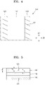
- FIGS. 4 and 5 show a planar structure and a cross-sectional structure of the insulating adhesive tape shown in FIG. 3 , respectively.
- an insulating adhesive tape 100 may be interposed between a plurality of battery cells C arranged in a row.
- the insulating adhesive tape 100 may serve to block the electrical interference and thermal interference between adjacent battery cells C.
- the case 10 of the battery cell C may have an electrical polarity, and may have the same polarity as one electrode plate of an electrode assembly (not shown).
- the insulating adhesive tape 100 may be interposed between the neighboring battery cells C to block electrical interference therebetween.
- the insulating adhesive tape 100 may structurally couple adjacent battery cells C to each other and bind a plurality of battery cells C to form a single pack.
- the plurality of battery cells C for forming a battery pack may be coupled to each other through the insulating adhesive tape 100, and a separate binding structure for binding the plurality of battery cells C may be omitted. That is, as a binding structure for combining the plurality of battery cells C into one pack, a plurality of metal plates surrounding a row of battery cells C, for example, an end plate (not shown) and a side plate (not shown) need not be applied, and thus these metal plates may be omitted.
- a low-weight battery pack may be provided by binding the plurality of battery cells C in the form of one pack through the insulating adhesive tape 100, and the volume and weigh of the battery pack may be reduced by omitting the binding structure made of a metal material.
- the insulating adhesive tape 100 is interposed between adjacent battery cells C, and may be disposed in a central region of the battery cells C.
- the battery cell C may experience swelling in which volume expands according to charging and discharging operations, and in this case, swelling may be concentrated in the central region of the battery cell C rather than the edge of the battery cell C where the bending or warping of the case 10, which may limit the swelling, is formed.
- the insulating adhesive tape 100 may be placed in the central region of the battery cell C, thereby blocking electrical interference and thermal interference between adjacent battery cells C that may be deformed in a direction approaching each other according to swelling.
- the insulating adhesive tape 100 may be placed over most of the region of the battery cell C, including the central region of the battery cell C.
- the insulating adhesive tape 100 may include an insulating film 110 and a double-sided adhesive film 120 attached to the insulating film 110.
- the insulating film 110 may be made of an insulating material to provide electrical insulation and thermal insulation between adjacent battery cells C, and may be formed in a size sufficient to cover most of the region of the battery cell C, including the central region of the battery cell C.
- the insulating film 110 may be formed in the shape of a rectangular sheet, and may be made of a ceramic material such as MICA.
- the double-sided adhesive film 120 may have adhesive properties on both surfaces thereof, that is, one surface and the other surface thereof so as to attach the insulating film 110 to the battery cell C. That is, one surface of the double-sided adhesive film 120 may be attached to the insulating film 110, and the other surface thereof may be attached to the battery cell C.
- the double-sided adhesive film 120 is limitedly attached to a part of the insulating film 110, and may not be attached over most of the region of the insulating film 110. That is, the attachment area between the insulating film 110 and the double-sided adhesive film 120 may be at least smaller than the total area of the insulating film 110.
- the double-sided adhesive film 120 may be formed in an area sufficient to provide adhesion between the insulating film 110 and the battery cell C.
- the double-sided adhesive film 120 may be formed in an excessive area, the insulating film 110 may be wrinkled or crumpled, and thus the attachment area of the double-sided adhesive film 120 is preferably limited to an appropriate level.
- the insulating film 110 may be wrinkled or crumpled, and thus a work for attaching the insulating adhesive tape 100 may be difficult.
- the insulating adhesive tape 100 is formed by attaching the double-sided adhesive film 120 onto the flat insulating film 110, and the insulating adhesive tape 100 formed in this way may be delivered by being wound in the form of a roll.
- the insulating adhesive tape 100 delivered in the form of a roll may be transported in one direction with transition from a state of being wound around an unroller, to a state of being flattened again, cut individually to a predetermined size, and then attached between the battery cells C.
- the insulating adhesive tape 100 repeats bending in the form of a roll and flattening, and in the attachment area between the insulating film 110 and the double-sided adhesive film 120 that are stickily attached to each other, stress may be accumulated to such an extent that movement therebetween is limited.
- the attachment area of the double-sided adhesive film 120 is formed in an excessive area exceeding an appropriate level, the double-sided adhesive film 120 restricts the movement of the insulating film 110 and the causes the crumples or wrinkles of the insulating film 110.
- the double-sided adhesive film 120 may be formed in a stripe pattern extending along one direction crossing the insulating film 110, and may include a pair of double-sided adhesive films 120 extending in parallel with each other. More specifically, the double-sided adhesive film 120 may be formed in a stripe pattern along the height direction Z2 of the battery cell C, and may be formed as a pair so as to be spaced apart from each other along the width direction Z3 of the battery cell C. In this embodiment, the length direction Z2 of the double-sided adhesive film 120 may correspond to the height direction Z2 of the battery cell C, and the width direction Z3 of the double-sided adhesive film 120 may correspond to the width direction Z3 of the battery cell C.
- the height direction Z2 of the battery cell C may refer to a direction facing an electrode surface of the battery cell C in which the first and second electrode terminals 11 and 12 are formed
- the width direction Z3 of the battery cell C may refer to a direction in which the first and second electrode terminals 11 and 12 face each other.
- the height direction Z2 of the battery cell C and the width direction Z3 of the battery cell C may correspond to directions perpendicular to each other.
- the double-sided adhesive film 120 may be formed in pairs spaced apart from each other along the width direction Z3 of the battery cell C, thereby providing a balanced adhesion between the battery cell C and the insulating film 110.
- the double-sided adhesive films 120 may be respectively formed on the front and back surfaces of the insulating film 110 along the arrangement direction Z1 of the battery cells C, so that the front battery cell (C) and the rear battery cell (C) may be attached to each other, and the battery cells C adjacent to each other in the front and rear directions may be firmly attached to each other through the double-sided adhesive films 120 formed in pairs at balanced positions along the width direction Z3 of the battery cells C.
- the front-rear direction may refer to an arrangement direction Z1 in which the battery cells C are arranged.
- the double-sided adhesive films 120 are formed in pairs spaced apart from each other along the width direction Z3 of the battery cell C, thereby providing an extra space capable of absorbing the volume expansion of swelling concentrated in the central region of the battery cell C.
- the double-sided adhesive films 120 may be formed in a stripe pattern along the width direction Z3 of the battery cell C, and may also be formed in a pair so as to be spaced apart from each other along the height direction Z2 of the battery cell C.
- the length direction Z3 of the double-sided adhesive film 120 may correspond to the width direction Z3 of the battery cell C
- the width direction Z2 of the double-sided adhesive film 120 may correspond to the height direction Z2 of the battery cell C.
- Cut lines 121 may be formed in the double-sided adhesive film 120.
- the cut lines 121 may allow relative deformation or positional movement between the double-sided adhesive film 120 and the insulating film 110, thereby relieving the stress between the double-sided adhesive film 120 and the insulating film 110 and thus preventing the crumples or wrinkles of the insulating film 110.
- the insulating adhesive tape 100 is formed by attaching the double-sided adhesive film 120 onto the flat insulating film 110, and the insulating adhesive tape 100 formed in this way may be delivered by being wound in the form of a roll. Then, the insulating adhesive tape 100 delivered in the form of a roll may be transported in one direction with transition from a state of being wound around an unroller, to a state of being flattened again, cut individually to a predetermined size, and then attached between the battery cells C.
- the double-sided adhesive film 120 attached to the flat insulating film 110 may cause the crumples or wrinkles of the insulating film 110 while being wound in a roll form, and in contrast, the double-sided adhesive film 120 may cause the crumples or wrinkles of the insulating film 110 while the insulating adhesive tape 100 wound around an unroller in a roll form spreading out again in a flat state.
- the insulating adhesive tape 100 repeats bending in the form of a roll and flattening, and in this case, as the movement between the insulating film 110 and the double-sided adhesive film 120, which are attached to each other in a sticky manner, is restricted, stress may accumulate between the insulating film 110 and the double-sided adhesive film 120, and the accumulation of stress may cause the crumple or wrinkle of the insulating film 110.
- the cut lines 121 are formed in the double-sided adhesive film 120, relative deformation or positional movement between the double-sided adhesive film 120 and the insulating film 110 may be allowed, thereby relieving the stress between the double-sided adhesive film 120 and the insulating film 110 and thus preventing the crumples or wrinkles of the insulating film 110 due to the accumulation of stress.
- the cut line 121 may be limitedly formed only to a cut thickness Tc corresponding to a part of the total thickness T of the double-sided adhesive film 120, and may not be formed to the remaining thickness Tr. That is, the remaining thickness Tr may include an intact double-sided adhesive film 120 in which the cut line 121 is not formed.
- the cut line 121 is formed over the entire thickness T of the double-sided adhesive film 120, since the double-sided adhesive film 120 is separated by a unit of the cut line 121, in the process of attaching the double-sided adhesive film 120, it is necessary to individually attach each piece of the double-sided adhesive film 120 separated by the cut line 121 to each piece without performing a continuous work, and there is a concern about the detachment of the torn double-sided adhesive film even after the attachment of the double-sided adhesive film 120, so that the cut line 121 to be formed in the double-sided adhesive film 120 may be limitedly formed only to the cut thickness Tc, which is a part of the total thickness T of the double-sided adhesive film 120, for the efficiency of the attachment operation and the strong attachment of the double-sided adhesive film 120.
- the remaining thickness Tr of the double-sided adhesive film 120 having an intact form, to which the cut line 121 is not formed and the double-sided adhesive film 120 is not cut may be formed to be 0.1 mm or more. If the residual thickness Tr of the double-sided adhesive film 120 is formed to be less than 0.1 mm, the double-sided adhesive film 120 may be separated by a unit of the cut line 121 even with a small shock or vibration.
- the cut line 121 of the double-sided adhesive film 120 is for relieving the stress between the double-sided adhesive film 120 and the insulating film 110 by allowing the relative deformation or positional movement between the double-sided adhesive film 120 and the insulating film 110, it is preferred that the cut thickness Tc of the cut line is formed to a sufficient thickness.
- the cut thickness Tc of the cut line 121 is formed too thin, it may not be sufficient to relieve the stress between the double-sided adhesive film 120 and the insulating film 110 and it may be difficult to prevent the insulating film 110 from being wrinkled.
- FIG. 6 shows a view for explaining a structure of a cut line of a double-sided adhesive film.
- a plurality of cut lines 121 may be formed with a pitch interval P therebetween in the length direction Z2 of the double-sided adhesive film 120.
- the cut lines 121 may be formed at a constant pitch interval P along the length direction Z2 of the double-sided adhesive film 120.
- the cut line 121 may include first and second ends 121a and 121b opposite to each other along the width direction Z3 of the double-sided adhesive film 120, and the pitch interval P may correspond to a distance between the same first ends 121a of the first and second cut lines 1211 and 1212 adjacent to each other or a distance between the same second ends 121b of the first and second cut lines 1211 and 1212 adjacent to each other.
- the width direction Z3 of the double-sided adhesive film 120 may refer to a direction perpendicular to the length direction Z2 of the double-sided adhesive film 120.
- the length direction Z2 and the width direction Z3 of the double-sided adhesive film 120 may correspond to the height direction Z2 and the width direction Z3 of the battery cell C, respectively.
- the first cut line 1211 and the second cut line 1212 adjacent to each other along the longitudinal direction Z2 of the double-sided adhesive film 120 are spaced apart from each other with a sufficient pitch interval P so as not to overlap each other along the width direction Z3 of the double-sided adhesive film 120.
- the first and second cut lines 1211 and 1212 are spaced apart from each other with a sufficient pitch interval P therebetween such that the projections (hatched regions in FIG. 6 ) of the first and second cut lines 1211 and 1212 do not overlap each other along the width direction Z3 of the double-sided adhesive film 120.
- the pitch interval P may be set within the range of 20 mm to 30 mm. It is preferred that the pitch interval P between the cut lines 121 adjacent to each other is set in relation to the shortest distance D between the cut lines 121 adjacent to each other, which will be described later.
- the shortest distance D between the first and second cut lines 1211 and 1212 adjacent to each other along the length direction Z2 of the double-sided adhesive film 120 is formed to have a value greater than at least 0 (zero).
- the first and second cut lines 1211 and 1212 may extend obliquely at a constant inclination angle ⁇ along the width direction Z3 of the double-sided adhesive film 120.
- the shortest distance D between the first and second cut lines 1211 and 1212 along the length direction Z2 of the double-sided adhesive film 120 may correspond to a distance between the first and second ends 121a and 121b opposite to each other along the width direction Z3 among the first and second cut lines 1211 and 1212.
- the shortest distance D between the first and second cut lines 1211 and 1212 may correspond to a distance from the second end 121b of the first cut line 1211 to the first end 121a of the second cut line 1212 along the length direction Z2 of the double-sided adhesive film 120.
- the second end 121b of the first cut line 1211 and the first end 121a of the second cut line 1212 are ends adjacent to each other along the length direction Z2 of the double-sided adhesive film 120, and the distance therebetween may correspond to the shortest distance D between the first and second cut lines 1211 and 1212.
- first end 121a of the first cut line 1211 and the second end 121b of the second cut line 1212 are ends arranged away from each other in the length direction Z2 of the double-sided adhesive film 120, and the distance therebetween may correspond to the longest distance between the first and second cut lines 1211 and 1212, but does not correspond to the shortest distance D.
- the pitch interval P of the first and second cut lines 1211 and 1212 may correspond to a distance between the same first ends 121a or second ends 121b of the first and second cut lines 1211 and 1212 along the width direction Z3.
- the shortest distance D between the first and second cut lines 1211 and 1212 may form an clearance width of a cutting path B through which a cutting blade passes in the width direction Z3 of the double-sided adhesive film 120. That is, the insulating adhesive tape 100 (or the double-sided adhesive film 120) may be individually cut to an appropriate size along the length direction Z2 and attached to the battery cell C. In this case, if the cutting path B and the cut line 121 are in contact with each other, some pieces of the double-sided adhesive film 120 are detached from the double-sided adhesive film 120 while the cutting path B and the cut-out line 121 are in contact with each other, so that an adhesion gap may occur. Accordingly, in the present disclosure, it is preferable to sufficiently secure the clearance width, that is, the shortest distance (D) between the first and second cut lines 1211 and 1212, such that the cutting path B and the cut line 121 do not come into contact with each other.
- the shortest distance D between the first and second cut lines 1211 and 1212 may correspond to an extra length remaining by excluding the projections (hatched areas in FIG. 6 ) of the first and second cut lines 1211 and 1212 from the pitch interval P of the first and second cut lines 1211 and 1212 (or the pitch interval of the cut line 121). If the cutting path B of the cutting blade passing in the width direction Z3 is formed inside the projection (hatched area in FIG.
- the double-sided adhesive film 120 is fragmented as the cutting path B and the first and second cut lines 1211 and 1212 come into contact with each other. Therefore, it is preferred that the cutting pass B passes through the extra length remaining by excluding the projections (hatched areas in FIG. 6 ) of the first and second cut lines 1211 and 1212 from the pitch interval P of the first and second cut lines 1211 and 1212 (or the pitch interval of the cut line 121) or passes through the shortest distance D between the second cut lines 1211 and 1212.
- the shortest distance D between the first and second cut lines 1211 and 1212 may be set to about half of the pitch interval P of the first and second cut lines 1211 and 1212.
- the cutting pass B may have a process margin to some degree, and even if there are some errors along the length direction Z2 of the double-sided adhesive film 120, it might be prevented adhesion gap of pieces of the double-sided adhesive film 120 being detached, in which the cutting blade crosses the projections (the hatched area in FIG. 6 ) of the first and second cut lines 1211 and 1212 and comes into contact with the first and second cut lines 1211 and 1212.
- the pitch interval P of the cut line 121 may be formed to be about 20 mm to 30 mm, and the shortest distance D between the first and second cut lines 1211 and 1212 adjacent to each other (or the clearance width of the cutting path B) may be formed to be about 10 mm to 15 mm, which is a half of the pitch interval P of the cut line 121.
- the pitch interval P of the cut line 121 may be formed to be 25 mm, and the shortest distance D between the first and second cut lines 1211 and 1212 adjacent to each other (or the clearance width of the cutting path B) may be formed to be 12.5 mm, which is a half of the pitch interval P of the cut line 121.
- the pitch interval P of the cut line 121 determines the shortest distance D between the first and second cut lines 1211 and 1212 adjacent to each other (or the clearance width of the cutting path B)
- the pitch interval P of the cut line 121 is formed to be smaller than the lower limit value (20 mm)
- the double-sided adhesive film 120 is torn apart and detached to form an adhesion gap.
- the pitch interval P of the cut line 121 is formed to be larger than the upper limit value (30 mm), that is, when the cut line 121 is sparsely formed along the length direction Z2 of the double-sided adhesive film 120, since the relative deformation or positional movement between the double-sided adhesive film 120 and the insulating film 110 may be allowed by the cut line 121, and thus it becomes difficult to achieve the purpose of relieving the stress therebetween and removing the crumples or wrinkles of the insulating film 110.
- the shortest distance D between the first and second cut lines 1211 and 1212 adjacent to each other may be set in relation to the thickness of the cutting blade (not shown).
- the shortest distance D between the first and second cut lines 1211 and 1212 adjacent to each other may be formed to be about 1 to 3 times of the thickness of the cutting blade (not shown), and preferably about 2 times of the thickness of the cutting blade (not shown).
- the double-sided adhesive film 120 may be torn apart and thus an adhesive gap may be formed.
- the pitch interval P of the cut line 121 is formed widely, considering that the relative deformation or positional movement between the double-sided adhesive film 120 and the insulating film 110 may be allowed by the cut line 121, it becomes difficult to achieve the purpose of relieving the stress therebetween and removing the crumples or wrinkles of the insulating film 110.
- a plurality of cut lines 121 may be formed along the length direction Z2 of the double-sided adhesive film 120, and in this case, it is preferred that the plurality of cut lines 121 are arranged in parallel at a constant inclination angle ⁇ . If the plurality of cut lines 121 are formed at different inclination angles, it may be difficult to secure a clearance width of the cutting path B through which the cutting blade passes in the process of individually cutting the continuously formed insulating adhesive tape 100 or double-sided adhesive film 120. That is, when the first and second cut lines 1211 and 1212 adjacent to each other extend at different angles, the shortest distance D therebetween may be narrower, compared to when the first and second cut lines 1211 and 1212 adjacent to each other extend in parallel to each other.
- the cut line 121 may be formed in a straight line extending obliquely along a diagonal direction inclined at a constant inclination angle ⁇ with respect to the width direction Z3 of the double-sided adhesive film 120.
- the cut line 121 may be modified into various shapes.
- the cut line 121' may be formed in a V-shape or an inverted V-shape in which two straight lines extending at different angles contact each other instead of on a straight line extending obliquely in an oblique direction.
- FIG. 7 the cut line 121' may be formed in a V-shape or an inverted V-shape in which two straight lines extending at different angles contact each other instead of on a straight line extending obliquely in an oblique direction.
- a cut line 121 on a straight line extending obliquely along an oblique direction may be preferred in that in the V-shape or inverted V-shape of the cut line 121', it is possible to form valleys in which foreign substances W such as moisture are accumulated.
- the present disclosure may be applied to a battery pack as an energy source capable of charging and discharging, and may also be applied to various appliances using the battery pack as a driving power source.
Landscapes
- Chemical & Material Sciences (AREA)
- Chemical Kinetics & Catalysis (AREA)
- Electrochemistry (AREA)
- General Chemical & Material Sciences (AREA)
- Organic Chemistry (AREA)
- Engineering & Computer Science (AREA)
- Aviation & Aerospace Engineering (AREA)
- Life Sciences & Earth Sciences (AREA)
- Biophysics (AREA)
- Computer Hardware Design (AREA)
- Battery Mounting, Suspending (AREA)
- Connection Of Batteries Or Terminals (AREA)
Abstract
Description
- The present disclosure relates to a battery pack.
- In general, a secondary battery is a battery that can be charged and discharged, unlike a primary battery that cannot be charged. Secondary batteries are used as energy sources for mobile devices, electric vehicles, hybrid vehicles, electric bicycles, uninterruptible power supply, and the like. The secondary batteries may be used in the form of a single battery depending on the type of external device to be applied, or may be used in the form of a module in which a plurality of batteries are connected and bundled as a unit.
- Small mobile appliances such as cell phones can be operated for a certain period of time with the power and capacity of a single battery. However, In the case of appliances that require long-term driving and high-power driving, such as electric vehicles and hybrid vehicles that consume a lot of power, due to the problem of power and capacity, a module type battery including a plurality of batteries is preferred, and an output voltage or an output current can be increased according to the number of built-in batteries.
- An embodiment of the present disclosure provides a battery pack having improved driving stability and advantageous in light reduction.
- An embodiment of the present disclosure provides a battery pack in which the structure of an insulating adhesive tape interposed between adjacent battery cells is improved, thereby preventing defects caused when the insulating adhesive tape is cut or attached.
- In order to solve the above problems, a battery back of the present disclosure includes
- a plurality of battery cells; and
- an insulating adhesive tape interposed between the battery cells adjacent to each other;
- wherein the insulating adhesive tape includes
- an insulating film; and
- at least one double-sided adhesive film attached between the insulating film and the battery cell and extending along one direction,
- wherein a plurality of cut lines are formed in the double-sided adhesive film.
- According to the present disclosure, there can be provided a battery pack in which adjacent battery cells are insulated from each other and structurally bonded to each other, thereby improving driving stability and enabling weigh reduction, and can be provided a battery pack in which cutting defects caused in the process of individually cutting a continuously supplied insulating adhesive tape can be prevented, a work for attaching the insulating adhesive tape can be easily performed by preventing the crumples or wrinkles of the insulating adhesive tape, and adhesion force between battery cells can be maintained firmly.
-
-
FIG. 1 shows a perspective view of a battery pack according to an embodiment of the present disclosure. -
FIG. 2 shows an exploded perspective view of the battery pack shown inFIG. 1 . -
FIG. 3 shows an exploded perspective view of a part of the battery pack shown inFIG. 2 . -
FIGS. 4 and 5 show a planar structure and a cross-sectional structure of the insulating adhesive tape shown inFIG. 3 , respectively. -
FIG. 6 shows a view for explaining a structure of a cut line of a double-sided adhesive film. -
FIG. 7 is a view showing a modified embodiment of the double-sided adhesive film shown inFIG. 6 . - A battery back of the present disclosure includes
- a plurality of battery cells; and
- an insulating adhesive tape interposed between the battery cells adjacent to each other;
- wherein the insulating adhesive tape includes
- an insulating film; and
- at least one double-sided adhesive film attached between the insulating film and the battery cell and extending along one direction,
- wherein a plurality of cut lines are formed in the double-sided adhesive film.
- For example, the cut lines may be formed on a straight line extending obliquely along an oblique direction with respect to a width direction of the double-sided adhesive film.
- For example, the cut lines may extend at a constant inclination angle with respect to a width direction of the double-sided adhesive film.
- For example, the cut lines may be formed at a regular pitch interval along a length direction of the double-sided adhesive film.
- For example, the pitch interval may be set in a range of 20 mm to 30 mm.
- For example, a shortest distance between the cut lines adjacent to each other in a length direction of the double-sided adhesive film may have a value greater than at least 0.
- For example, the shortest distance between the cut lines adjacent to each other may be set in a range of 10 mm to 15 mm.
- For example, the cut line may include first and second ends opposite to each other along a width direction of the double-sided adhesive film, and
the shortest distance between the cut lines adjacent to each other may correspond to a distance between the first and second ends opposite to each other. - For example, the cut lines may be formed at a regular pitch interval along the length direction of the double-sided adhesive film, and
the shortest distance between the cut lines adjacent to each other may be formed to be a half of the pitch interval. - For example, the cut line may include first and second ends opposite to each other along a width direction of the double-sided adhesive film, and
the pitch interval may correspond to a distance between the same first ends or second ends of the cut lines adjacent to each other. - For example, the cut line may be limitedly formed over a cut thickness corresponding to a part of a total thickness of the double-sided adhesive film.
- For example, an attachment area of the double-sided adhesive film attached to the insulating film may be smaller than an area of the insulating film.
- For example, the double-sided adhesive film may be formed in a stripe pattern extending along one direction crossing the insulating film.
- For example, the double-sided adhesive film may extend along a height direction of the battery cell.
- For example, the double-sided adhesive film may be formed in pairs spaced apart from each other along a width direction of the battery cell.
- For example, along an arrangement direction of the battery cells, the double-sided adhesive film may be attached to front and back surfaces of the insulating film, respectively.
- Hereinafter, a battery pack according to a preferred embodiment of the present disclosure will be described with reference to the accompanying drawings.
-
FIG. 1 shows a perspective view of a battery pack according to an embodiment of the present disclosure.FIG. 2 shows an exploded perspective view of the battery pack shown inFIG. 1 . - Referring to
FIGS. 1 and2 , the battery pack may include a plurality of battery cells C, abus bar 200 for electrically connecting the plurality of battery cells C, and abus bar holder 150 for providing electrical insulation between thebus bar 200 and the battery cells C. - The battery cell (C) may include an electrode assembly (not shown) and a
case 10 for accommodating the electrode assembly (not shown), and first andsecond electrode terminals case 10. The first andsecond electrode terminals case 10, and any one of the first andsecond electrode terminals first electrode terminal 11 may form a conductive connection with thecase 10 and may have the same polarity as thecase 10. In this case, thefirst electrode terminal 11 may be omitted, and thecase 10 may serve as thefirst electrode terminal 11. Meanwhile, thesecond electrode terminal 12 may form an insulating connection with thecase 10. - The
bus bar 200 may connect a pair of adjacent battery cells C in parallel with the same polarity, and may connect a pair of adjacent battery cells C in parallel with each other to form a parallel module PM. Thebus bar 200 may connect a pair of parallelly connected battery cells C (parallel module PM) and another pair of parallelly connected battery cells C (another parallel module PM) in series with opposite polarities. Thebus bar 200 may electrically connect a pair of parallelly connected battery cells C (parallel module PM) and another pair of parallelly connected battery cells C (another parallel module PM) in series, but a pair of battery cells C (parallel module PM) and another pair of battery cells C (another parallel module PM), which are connected by thebus bar 200, may not be adjacent to each other. As such, first andsecond output terminals bus bar 200 connects non-adjacent battery cells C, that is, non-adjacent parallel modules PM in series. - The
bus bar holder 150 may provide insulation between the battery cell C and thebus bar 200, and may include a terminal hole 150' for allowing coupling between the first andsecond electrode terminals bus bar 200. A positioning rib R for aligning the assembly position of thebus bar 200 may be formed around the terminal hole 150' of thebus bar holder 150. -
FIG. 3 shows an exploded perspective view of a part of the battery pack shown inFIG. 2 .FIGS. 4 and 5 show a planar structure and a cross-sectional structure of the insulating adhesive tape shown inFIG. 3 , respectively. - Referring to
FIG. 3 , referring toFIG. 3 , an insulatingadhesive tape 100 may be interposed between a plurality of battery cells C arranged in a row. The insulatingadhesive tape 100 may serve to block the electrical interference and thermal interference between adjacent battery cells C. For example, thecase 10 of the battery cell C may have an electrical polarity, and may have the same polarity as one electrode plate of an electrode assembly (not shown). In this case, the insulatingadhesive tape 100 may be interposed between the neighboring battery cells C to block electrical interference therebetween. - The insulating
adhesive tape 100 may structurally couple adjacent battery cells C to each other and bind a plurality of battery cells C to form a single pack. For example, in an embodiment of the present disclosure, the plurality of battery cells C for forming a battery pack may be coupled to each other through the insulatingadhesive tape 100, and a separate binding structure for binding the plurality of battery cells C may be omitted. That is, as a binding structure for combining the plurality of battery cells C into one pack, a plurality of metal plates surrounding a row of battery cells C, for example, an end plate (not shown) and a side plate (not shown) need not be applied, and thus these metal plates may be omitted. As such, a low-weight battery pack may be provided by binding the plurality of battery cells C in the form of one pack through the insulatingadhesive tape 100, and the volume and weigh of the battery pack may be reduced by omitting the binding structure made of a metal material. - The insulating
adhesive tape 100 is interposed between adjacent battery cells C, and may be disposed in a central region of the battery cells C. The battery cell C may experience swelling in which volume expands according to charging and discharging operations, and in this case, swelling may be concentrated in the central region of the battery cell C rather than the edge of the battery cell C where the bending or warping of thecase 10, which may limit the swelling, is formed. In this case, the insulatingadhesive tape 100 may be placed in the central region of the battery cell C, thereby blocking electrical interference and thermal interference between adjacent battery cells C that may be deformed in a direction approaching each other according to swelling. In an embodiment of the present disclosure, the insulatingadhesive tape 100 may be placed over most of the region of the battery cell C, including the central region of the battery cell C. - The insulating
adhesive tape 100 may include an insulatingfilm 110 and a double-sided adhesive film 120 attached to the insulatingfilm 110. The insulatingfilm 110 may be made of an insulating material to provide electrical insulation and thermal insulation between adjacent battery cells C, and may be formed in a size sufficient to cover most of the region of the battery cell C, including the central region of the battery cell C. For example, the insulatingfilm 110 may be formed in the shape of a rectangular sheet, and may be made of a ceramic material such as MICA. - The double-
sided adhesive film 120 may have adhesive properties on both surfaces thereof, that is, one surface and the other surface thereof so as to attach the insulatingfilm 110 to the battery cell C. That is, one surface of the double-sided adhesive film 120 may be attached to the insulatingfilm 110, and the other surface thereof may be attached to the battery cell C. The double-sided adhesive film 120 is limitedly attached to a part of the insulatingfilm 110, and may not be attached over most of the region of the insulatingfilm 110. That is, the attachment area between the insulatingfilm 110 and the double-sided adhesive film 120 may be at least smaller than the total area of the insulatingfilm 110. - The double-
sided adhesive film 120 may be formed in an area sufficient to provide adhesion between the insulatingfilm 110 and the battery cell C. When the double-sided adhesive film 120 is formed in an excessive area, the insulatingfilm 110 may be wrinkled or crumpled, and thus the attachment area of the double-sided adhesive film 120 is preferably limited to an appropriate level. - If the double-
sided adhesive film 120 is excessively attached over most of the region of the insulatingfilm 110, the insulatingfilm 110 may be wrinkled or crumpled, and thus a work for attaching the insulatingadhesive tape 100 may be difficult. For example, with respect to the formation of the insulatingadhesive tape 100, the insulatingadhesive tape 100 is formed by attaching the double-sided adhesive film 120 onto the flatinsulating film 110, and the insulatingadhesive tape 100 formed in this way may be delivered by being wound in the form of a roll. Then, the insulatingadhesive tape 100 delivered in the form of a roll may be transported in one direction with transition from a state of being wound around an unroller, to a state of being flattened again, cut individually to a predetermined size, and then attached between the battery cells C. As such, the insulatingadhesive tape 100 repeats bending in the form of a roll and flattening, and in the attachment area between the insulatingfilm 110 and the double-sided adhesive film 120 that are stickily attached to each other, stress may be accumulated to such an extent that movement therebetween is limited. In this case, when the attachment area of the double-sided adhesive film 120 is formed in an excessive area exceeding an appropriate level, the double-sided adhesive film 120 restricts the movement of the insulatingfilm 110 and the causes the crumples or wrinkles of the insulatingfilm 110. - In an embodiment of the present disclosure, the double-
sided adhesive film 120 may be formed in a stripe pattern extending along one direction crossing the insulatingfilm 110, and may include a pair of double-sidedadhesive films 120 extending in parallel with each other. More specifically, the double-sided adhesive film 120 may be formed in a stripe pattern along the height direction Z2 of the battery cell C, and may be formed as a pair so as to be spaced apart from each other along the width direction Z3 of the battery cell C. In this embodiment, the length direction Z2 of the double-sided adhesive film 120 may correspond to the height direction Z2 of the battery cell C, and the width direction Z3 of the double-sided adhesive film 120 may correspond to the width direction Z3 of the battery cell C. Throughout the present specification, the height direction Z2 of the battery cell C may refer to a direction facing an electrode surface of the battery cell C in which the first andsecond electrode terminals second electrode terminals - The double-
sided adhesive film 120 may be formed in pairs spaced apart from each other along the width direction Z3 of the battery cell C, thereby providing a balanced adhesion between the battery cell C and the insulatingfilm 110. In this case, the double-sidedadhesive films 120 may be respectively formed on the front and back surfaces of the insulatingfilm 110 along the arrangement direction Z1 of the battery cells C, so that the front battery cell (C) and the rear battery cell (C) may be attached to each other, and the battery cells C adjacent to each other in the front and rear directions may be firmly attached to each other through the double-sidedadhesive films 120 formed in pairs at balanced positions along the width direction Z3 of the battery cells C. Throughout the present specification, the front-rear direction may refer to an arrangement direction Z1 in which the battery cells C are arranged. - The double-sided
adhesive films 120 are formed in pairs spaced apart from each other along the width direction Z3 of the battery cell C, thereby providing an extra space capable of absorbing the volume expansion of swelling concentrated in the central region of the battery cell C. Meanwhile, in another embodiment of the present disclosure, the double-sidedadhesive films 120 may be formed in a stripe pattern along the width direction Z3 of the battery cell C, and may also be formed in a pair so as to be spaced apart from each other along the height direction Z2 of the battery cell C. In this embodiment, the length direction Z3 of the double-sided adhesive film 120 may correspond to the width direction Z3 of the battery cell C, and the width direction Z2 of the double-sided adhesive film 120 may correspond to the height direction Z2 of the battery cell C. - Cut
lines 121 may be formed in the double-sided adhesive film 120. The cut lines 121 may allow relative deformation or positional movement between the double-sided adhesive film 120 and the insulatingfilm 110, thereby relieving the stress between the double-sided adhesive film 120 and the insulatingfilm 110 and thus preventing the crumples or wrinkles of the insulatingfilm 110. - As described above, with respect to the formation of the insulating
adhesive tape 100, the insulatingadhesive tape 100 is formed by attaching the double-sided adhesive film 120 onto the flatinsulating film 110, and the insulatingadhesive tape 100 formed in this way may be delivered by being wound in the form of a roll. Then, the insulatingadhesive tape 100 delivered in the form of a roll may be transported in one direction with transition from a state of being wound around an unroller, to a state of being flattened again, cut individually to a predetermined size, and then attached between the battery cells C. In this case, the double-sided adhesive film 120 attached to the flatinsulating film 110 may cause the crumples or wrinkles of the insulatingfilm 110 while being wound in a roll form, and in contrast, the double-sided adhesive film 120 may cause the crumples or wrinkles of the insulatingfilm 110 while the insulatingadhesive tape 100 wound around an unroller in a roll form spreading out again in a flat state. That is, the insulatingadhesive tape 100 repeats bending in the form of a roll and flattening, and in this case, as the movement between the insulatingfilm 110 and the double-sided adhesive film 120, which are attached to each other in a sticky manner, is restricted, stress may accumulate between the insulatingfilm 110 and the double-sided adhesive film 120, and the accumulation of stress may cause the crumple or wrinkle of the insulatingfilm 110. - In the present disclosure, since the
cut lines 121 are formed in the double-sided adhesive film 120, relative deformation or positional movement between the double-sided adhesive film 120 and the insulatingfilm 110 may be allowed, thereby relieving the stress between the double-sided adhesive film 120 and the insulatingfilm 110 and thus preventing the crumples or wrinkles of the insulatingfilm 110 due to the accumulation of stress. - Referring to
FIG. 5 , thecut line 121 may be limitedly formed only to a cut thickness Tc corresponding to a part of the total thickness T of the double-sided adhesive film 120, and may not be formed to the remaining thickness Tr. That is, the remaining thickness Tr may include an intact double-sided adhesive film 120 in which thecut line 121 is not formed. If thecut line 121 is formed over the entire thickness T of the double-sided adhesive film 120, since the double-sided adhesive film 120 is separated by a unit of thecut line 121, in the process of attaching the double-sided adhesive film 120, it is necessary to individually attach each piece of the double-sided adhesive film 120 separated by thecut line 121 to each piece without performing a continuous work, and there is a concern about the detachment of the torn double-sided adhesive film even after the attachment of the double-sided adhesive film 120, so that thecut line 121 to be formed in the double-sided adhesive film 120 may be limitedly formed only to the cut thickness Tc, which is a part of the total thickness T of the double-sided adhesive film 120, for the efficiency of the attachment operation and the strong attachment of the double-sided adhesive film 120. For example, of the total thickness T of the double-sided adhesive film 120, the remaining thickness Tr of the double-sided adhesive film 120 having an intact form, to which thecut line 121 is not formed and the double-sided adhesive film 120 is not cut, may be formed to be 0.1 mm or more. If the residual thickness Tr of the double-sided adhesive film 120 is formed to be less than 0.1 mm, the double-sided adhesive film 120 may be separated by a unit of thecut line 121 even with a small shock or vibration. - Meanwhile, the
cut line 121 of the double-sided adhesive film 120 is for relieving the stress between the double-sided adhesive film 120 and the insulatingfilm 110 by allowing the relative deformation or positional movement between the double-sided adhesive film 120 and the insulatingfilm 110, it is preferred that the cut thickness Tc of the cut line is formed to a sufficient thickness. When the cut thickness Tc of thecut line 121 is formed too thin, it may not be sufficient to relieve the stress between the double-sided adhesive film 120 and the insulatingfilm 110 and it may be difficult to prevent theinsulating film 110 from being wrinkled. -
FIG. 6 shows a view for explaining a structure of a cut line of a double-sided adhesive film. - Referring to
FIG. 6 , a plurality ofcut lines 121 may be formed with a pitch interval P therebetween in the length direction Z2 of the double-sided adhesive film 120. For example, the cut lines 121 may be formed at a constant pitch interval P along the length direction Z2 of the double-sided adhesive film 120. Thecut line 121 may include first andsecond ends sided adhesive film 120, and the pitch interval P may correspond to a distance between the same first ends 121a of the first andsecond cut lines second cut lines sided adhesive film 120 may refer to a direction perpendicular to the length direction Z2 of the double-sided adhesive film 120. For example, in an embodiment of the present disclosure, the length direction Z2 and the width direction Z3 of the double-sided adhesive film 120 may correspond to the height direction Z2 and the width direction Z3 of the battery cell C, respectively. - With respect to the setting of the pitch interval P, it is preferred that the
first cut line 1211 and thesecond cut line 1212 adjacent to each other along the longitudinal direction Z2 of the double-sided adhesive film 120 are spaced apart from each other with a sufficient pitch interval P so as not to overlap each other along the width direction Z3 of the double-sided adhesive film 120. For example, it is preferred that the first andsecond cut lines FIG. 6 ) of the first andsecond cut lines sided adhesive film 120. In an embodiment of the present disclosure, the pitch interval P may be set within the range of 20 mm to 30 mm. It is preferred that the pitch interval P between thecut lines 121 adjacent to each other is set in relation to the shortest distance D between thecut lines 121 adjacent to each other, which will be described later. - It is preferred that the shortest distance D between the first and
second cut lines second cut lines sided adhesive film 120. In this case, the shortest distance D between the first andsecond cut lines second ends second cut lines - More specifically, the shortest distance D between the first and
second cut lines 1211 and 1212 (or the shortest distance D between neighboring cut lines 121) may correspond to a distance from thesecond end 121b of thefirst cut line 1211 to thefirst end 121a of thesecond cut line 1212 along the length direction Z2 of the double-sided adhesive film 120. Here, thesecond end 121b of thefirst cut line 1211 and thefirst end 121a of thesecond cut line 1212 are ends adjacent to each other along the length direction Z2 of the double-sided adhesive film 120, and the distance therebetween may correspond to the shortest distance D between the first andsecond cut lines first end 121a of thefirst cut line 1211 and thesecond end 121b of thesecond cut line 1212 are ends arranged away from each other in the length direction Z2 of the double-sided adhesive film 120, and the distance therebetween may correspond to the longest distance between the first andsecond cut lines - As described above, unlike the shortest distance D between the first and
second cut lines second cut lines 1211 and 1212 (or the pitch interval P of the cut line 121) may correspond to a distance between the same first ends 121a or second ends 121b of the first andsecond cut lines - In order to separate the continuously formed insulating adhesive tape 100 (or double-sided adhesive film 120) individually, the shortest distance D between the first and
second cut lines sided adhesive film 120. That is, the insulating adhesive tape 100 (or the double-sided adhesive film 120) may be individually cut to an appropriate size along the length direction Z2 and attached to the battery cell C. In this case, if the cutting path B and thecut line 121 are in contact with each other, some pieces of the double-sided adhesive film 120 are detached from the double-sided adhesive film 120 while the cutting path B and the cut-outline 121 are in contact with each other, so that an adhesion gap may occur. Accordingly, in the present disclosure, it is preferable to sufficiently secure the clearance width, that is, the shortest distance (D) between the first andsecond cut lines cut line 121 do not come into contact with each other. - Referring to
FIG. 6 , in an embodiment of the present disclosure, the shortest distance D between the first andsecond cut lines 1211 and 1212 (or the shortest distance D between neighboring cut lines 121) may correspond to an extra length remaining by excluding the projections (hatched areas inFIG. 6 ) of the first andsecond cut lines second cut lines 1211 and 1212 (or the pitch interval of the cut line 121). If the cutting path B of the cutting blade passing in the width direction Z3 is formed inside the projection (hatched area inFIG. 6 ) of the first andsecond cut lines adhesive tape 100 or the double-sided adhesive film 120 individually, the double-sided adhesive film 120 is fragmented as the cutting path B and the first andsecond cut lines FIG. 6 ) of the first andsecond cut lines second cut lines 1211 and 1212 (or the pitch interval of the cut line 121) or passes through the shortest distance D between thesecond cut lines - In an embodiment of the present invention, the shortest distance D between the first and
second cut lines second cut lines second cut lines second cut lines sided adhesive film 120, it might be prevented adhesion gap of pieces of the double-sided adhesive film 120 being detached, in which the cutting blade crosses the projections (the hatched area inFIG. 6 ) of the first andsecond cut lines second cut lines - More specifically, the pitch interval P of the
cut line 121 may be formed to be about 20 mm to 30 mm, and the shortest distance D between the first andsecond cut lines cut line 121. In an embodiment of the present disclosure, the pitch interval P of thecut line 121 may be formed to be 25 mm, and the shortest distance D between the first andsecond cut lines cut line 121. - As such, since the pitch interval P of the
cut line 121 determines the shortest distance D between the first andsecond cut lines cut line 121 is formed to be smaller than the lower limit value (20 mm), as thecut line 121 and the cutting path B come into contact with each other, the double-sided adhesive film 120 is torn apart and detached to form an adhesion gap. In addition, when the pitch interval P of thecut line 121 is formed to be larger than the upper limit value (30 mm), that is, when thecut line 121 is sparsely formed along the length direction Z2 of the double-sided adhesive film 120, since the relative deformation or positional movement between the double-sided adhesive film 120 and the insulatingfilm 110 may be allowed by thecut line 121, and thus it becomes difficult to achieve the purpose of relieving the stress therebetween and removing the crumples or wrinkles of the insulatingfilm 110. - In an embodiment of the present disclosure, the shortest distance D between the first and
second cut lines second cut lines second cut lines cut line 121 and the cutting path B come into contact with each other, the double-sided adhesive film 120 may be torn apart and thus an adhesive gap may be formed. In addition, when the shortest distance D between the first andsecond cut lines cut line 121 is formed widely, considering that the relative deformation or positional movement between the double-sided adhesive film 120 and the insulatingfilm 110 may be allowed by thecut line 121, it becomes difficult to achieve the purpose of relieving the stress therebetween and removing the crumples or wrinkles of the insulatingfilm 110. - Referring to
FIG. 6 , a plurality ofcut lines 121 may be formed along the length direction Z2 of the double-sided adhesive film 120, and in this case, it is preferred that the plurality ofcut lines 121 are arranged in parallel at a constant inclination angle θ. If the plurality ofcut lines 121 are formed at different inclination angles, it may be difficult to secure a clearance width of the cutting path B through which the cutting blade passes in the process of individually cutting the continuously formed insulatingadhesive tape 100 or double-sided adhesive film 120. That is, when the first andsecond cut lines second cut lines - In an embodiment of the present disclosure, the
cut line 121 may be formed in a straight line extending obliquely along a diagonal direction inclined at a constant inclination angle θ with respect to the width direction Z3 of the double-sided adhesive film 120. In another embodiment of the present invention, thecut line 121 may be modified into various shapes. For example, as may be seen in the double-sided adhesive film 120' shown inFIG. 7 , the cut line 121' may be formed in a V-shape or an inverted V-shape in which two straight lines extending at different angles contact each other instead of on a straight line extending obliquely in an oblique direction. However, as shown inFIG. 6 , acut line 121 on a straight line extending obliquely along an oblique direction may be preferred in that in the V-shape or inverted V-shape of the cut line 121', it is possible to form valleys in which foreign substances W such as moisture are accumulated. - Although the present invention has been described with reference to the embodiments shown in the accompanying drawings, this is merely exemplary, it will be understood that those skilled in the art to which the present disclosure belongs can make various modifications and equivalent other embodiments therefrom.
- The present disclosure may be applied to a battery pack as an energy source capable of charging and discharging, and may also be applied to various appliances using the battery pack as a driving power source.
Claims (16)
- A battery pack comprising:a plurality of battery cells; andan insulating adhesive tape interposed between the battery cells adjacent to each other,wherein the insulating adhesive tape comprises:an insulating film; andat least one double-sided adhesive film attached between the insulating film and the battery cells and extending along one direction,wherein a plurality of cut lines are formed in the double-sided adhesive film.
- The battery pack of claim 1, wherein the cut lines are formed on a straight line extending obliquely along an oblique direction with respect to a width direction of the double-sided adhesive film.
- The battery pack of claim 1, wherein the cut lines extend at a constant inclination angle with respect to a width direction of the double-sided adhesive film.
- The battery pack of claim 1, wherein the cut lines are formed at a regular pitch interval along a length direction of the double-sided adhesive film.
- The battery pack of claim 4, wherein the pitch interval is set in a range of 20 mm to 30 mm.
- The battery pack of claim 1, wherein a shortest distance between the cut lines adjacent to each other in a length direction of the double-sided adhesive film has a value greater than at least 0.
- The battery pack of claim 6, wherein the shortest distance between the cut lines adjacent to each other is set in a range of 10 mm to 15 mm.
- The battery pack of claim 6, whereinthe cut line includes first and second ends opposite to each other along a width direction of the double-sided adhesive film, andthe shortest distance between the cut lines adjacent to each other corresponds to a distance between the first and second ends opposite to each other.
- The battery pack of claim 6, whereinthe cut lines are formed at a regular pitch interval along the length direction of the double-sided adhesive film, andthe shortest distance between the cut lines adjacent to each other is formed to be a half of the pitch interval.
- The battery pack of claim 9, whereinthe cut line includes first and second ends opposite to each other along a width direction of the double-sided adhesive film, andthe pitch interval corresponds to a distance between the same first ends or second ends of the cut lines adjacent to each other.
- The battery pack of claim 1, wherein the cut line is limitedly formed over a cut thickness corresponding to a part of a total thickness of the double-sided adhesive film.
- The battery pack of claim 1, wherein an attachment area of the double-sided adhesive film attached to the insulating film is smaller than an area of the insulating film.
- The battery pack of claim 1, wherein the double-sided adhesive film is formed in a stripe pattern extending along one direction crossing the insulating film.
- The battery pack of claim 1, wherein the double-sided adhesive film extends along a height direction of the battery cell.
- The battery pack of claim 1, wherein the double-sided adhesive film is formed in pairs spaced apart from each other along a width direction of the battery cell.
- The battery pack of claim 1, wherein along an arrangement direction of the battery cells, the double-sided adhesive film is attached to front and back surfaces of the insulating film, respectively.
Applications Claiming Priority (2)
| Application Number | Priority Date | Filing Date | Title |
|---|---|---|---|
| KR1020190074124A KR102754048B1 (en) | 2019-06-21 | 2019-06-21 | Battery pack |
| PCT/KR2020/007893 WO2020256428A2 (en) | 2019-06-21 | 2020-06-18 | Battery pack |
Publications (2)
| Publication Number | Publication Date |
|---|---|
| EP3988627A2 true EP3988627A2 (en) | 2022-04-27 |
| EP3988627A4 EP3988627A4 (en) | 2023-07-19 |
Family
ID=74040246
Family Applications (1)
| Application Number | Title | Priority Date | Filing Date |
|---|---|---|---|
| EP20825551.3A Pending EP3988627A4 (en) | 2019-06-21 | 2020-06-18 | Battery pack |
Country Status (5)
| Country | Link |
|---|---|
| US (1) | US12308454B2 (en) |
| EP (1) | EP3988627A4 (en) |
| KR (1) | KR102754048B1 (en) |
| CN (1) | CN114026737B (en) |
| WO (1) | WO2020256428A2 (en) |
Cited By (1)
| Publication number | Priority date | Publication date | Assignee | Title |
|---|---|---|---|---|
| WO2024120870A1 (en) * | 2022-12-07 | 2024-06-13 | Northvolt Ab | A method of arranging battery cells |
Families Citing this family (3)
| Publication number | Priority date | Publication date | Assignee | Title |
|---|---|---|---|---|
| WO2024246685A1 (en) * | 2023-06-02 | 2024-12-05 | 3M Innovative Properties Company | Articles comprising adhesive and film suitable for disassembly and methods |
| WO2024243984A1 (en) * | 2023-06-02 | 2024-12-05 | 3M Innovative Properties Company | Articles comprising adhesive and multilayer film suitable for disassembly and methods |
| US20250079557A1 (en) * | 2023-09-06 | 2025-03-06 | Ford Global Technologies, Llc | Traction battery pack thermal management assembly |
Family Cites Families (23)
| Publication number | Priority date | Publication date | Assignee | Title |
|---|---|---|---|---|
| AU687429B2 (en) | 1993-08-27 | 1998-02-26 | Minnesota Mining And Manufacturing Company | Flying splice adhesive tape |
| US7951479B2 (en) * | 2005-05-11 | 2011-05-31 | Cardiac Pacemakers, Inc. | Method and apparatus for porous insulative film for insulating energy source layers |
| JP2005085570A (en) | 2003-09-08 | 2005-03-31 | Hitachi Maxell Ltd | THIN FILM ELECTRODE, ITS MANUFACTURING METHOD, AND LITHIUM SECONDARY BATTERY USING THE THIN FILM ELECTRODE |
| KR100571269B1 (en) * | 2004-09-22 | 2006-04-13 | 삼성에스디아이 주식회사 | Pouches for secondary batteries and pouch type secondary batteries |
| KR100878703B1 (en) | 2005-11-28 | 2009-01-14 | 주식회사 엘지화학 | Small battery pack with PCM in side sealing part |
| JP2010198770A (en) * | 2009-02-23 | 2010-09-09 | Sanyo Electric Co Ltd | Method and apparatus for manufacturing wound electrode assembly |
| KR101172231B1 (en) | 2009-11-30 | 2012-08-07 | 삼성에스디아이 주식회사 | Protection Tape and Secondary Battery having the same |
| DE102012211653A1 (en) * | 2012-07-04 | 2014-05-22 | Bayerische Motoren Werke Aktiengesellschaft | Energy storage module for power supply device used in motor car, has insulation film whose sides are bonded with adjacent memory cells respectively, and that is arranged parallel to end plate |
| CN103844552A (en) * | 2012-11-30 | 2014-06-11 | 张成龙 | Touch type artificial fingernail |
| KR102065748B1 (en) * | 2013-01-07 | 2020-01-14 | 에스케이이노베이션 주식회사 | Thermal pad for secondary battery and Battery module having the same |
| KR101678534B1 (en) * | 2013-02-05 | 2016-11-22 | 삼성에스디아이 주식회사 | Battery module with insulating member |
| JP2015048430A (en) * | 2013-09-03 | 2015-03-16 | 日東電工株式会社 | Double-sided adhesive tape |
| KR102020635B1 (en) | 2013-11-20 | 2019-09-10 | 삼성에스디아이 주식회사 | Battery Pack |
| JP6264165B2 (en) * | 2014-04-09 | 2018-01-24 | 株式会社豊田自動織機 | Battery unit manufacturing method and battery unit |
| JP6574598B2 (en) * | 2014-04-24 | 2019-09-11 | 日東電工株式会社 | Pressure sensitive adhesive sheet |
| CN106450406A (en) | 2015-08-07 | 2017-02-22 | 宁德时代新能源科技股份有限公司 | Battery module |
| KR102024326B1 (en) * | 2015-10-14 | 2019-09-23 | 주식회사 엘지화학 | Battery module and battery pack comprising the smae |
| JP6093460B1 (en) | 2016-02-08 | 2017-03-08 | シーベル産業株式会社 | Elastic adhesive tape |
| CN206490118U (en) * | 2017-02-27 | 2017-09-12 | 宁德时代新能源科技股份有限公司 | A kind of power battery module |
| CN109216600B (en) * | 2017-06-30 | 2021-09-03 | 比亚迪股份有限公司 | Battery module |
| CN109216594B (en) * | 2017-06-30 | 2022-03-15 | 比亚迪股份有限公司 | Battery unit and battery module |
| KR102461577B1 (en) | 2017-07-17 | 2022-11-01 | 삼성에스디아이 주식회사 | Secondary Battery Module |
| CN109904353A (en) | 2019-01-31 | 2019-06-18 | 欣旺达电子股份有限公司 | The coating method and rectangular lithium ion battery of coat insulating film |
-
2019
- 2019-06-21 KR KR1020190074124A patent/KR102754048B1/en active Active
-
2020
- 2020-06-18 US US17/621,289 patent/US12308454B2/en active Active
- 2020-06-18 EP EP20825551.3A patent/EP3988627A4/en active Pending
- 2020-06-18 CN CN202080045382.3A patent/CN114026737B/en active Active
- 2020-06-18 WO PCT/KR2020/007893 patent/WO2020256428A2/en not_active Ceased
Cited By (1)
| Publication number | Priority date | Publication date | Assignee | Title |
|---|---|---|---|---|
| WO2024120870A1 (en) * | 2022-12-07 | 2024-06-13 | Northvolt Ab | A method of arranging battery cells |
Also Published As
| Publication number | Publication date |
|---|---|
| WO2020256428A2 (en) | 2020-12-24 |
| CN114026737A (en) | 2022-02-08 |
| EP3988627A4 (en) | 2023-07-19 |
| CN114026737B (en) | 2023-11-17 |
| US20220223961A1 (en) | 2022-07-14 |
| WO2020256428A3 (en) | 2021-04-15 |
| US12308454B2 (en) | 2025-05-20 |
| KR102754048B1 (en) | 2025-01-14 |
| KR20200145297A (en) | 2020-12-30 |
Similar Documents
| Publication | Publication Date | Title |
|---|---|---|
| US12308454B2 (en) | Battery pack | |
| US11888125B2 (en) | Battery module having connector mounted on FPCB, and battery pack and vehicle comprising same | |
| US20210257649A1 (en) | Secondary battery having improved current-collecting structure | |
| EP2735041B1 (en) | Power supply unit for electric vehicle | |
| CN109962192A (en) | battery module | |
| JP4084596B2 (en) | Plate battery electrode connection structure | |
| EP2654102B1 (en) | Battery stack | |
| JP7123472B2 (en) | Battery module and manufacturing method thereof | |
| KR101312425B1 (en) | Secondary battery pack and connector utilized therein | |
| JP7799044B2 (en) | Cell unit, battery and vehicle | |
| CN109830627A (en) | Battery module | |
| KR20200069041A (en) | Battery module | |
| JP2020525996A (en) | Battery module | |
| EP2490277B1 (en) | Battery Module | |
| JP2020173900A (en) | Laminated battery | |
| EP1808915A1 (en) | Conductive plate and secondary battery pack using conductive plate | |
| KR20210007244A (en) | Battery module, battery pack and vehicle comprising the same | |
| CN103633277A (en) | Cell connecting piece, battery cell module and manufacturing method thereof, battery and vehicle motor | |
| KR102813933B1 (en) | Battery module and battery pack including the same | |
| KR102802529B1 (en) | Battery module and battery pack including the same | |
| KR20170028069A (en) | Battery module | |
| JP3283409B2 (en) | Storage battery unit battery | |
| KR20070025735A (en) | Partition wall of the secondary battery module and the secondary battery module | |
| CN116157949A (en) | Battery module and battery pack including the battery module | |
| KR20220158538A (en) | Battery pack |
Legal Events
| Date | Code | Title | Description |
|---|---|---|---|
| STAA | Information on the status of an ep patent application or granted ep patent |
Free format text: STATUS: THE INTERNATIONAL PUBLICATION HAS BEEN MADE |
|
| PUAI | Public reference made under article 153(3) epc to a published international application that has entered the european phase |
Free format text: ORIGINAL CODE: 0009012 |
|
| STAA | Information on the status of an ep patent application or granted ep patent |
Free format text: STATUS: REQUEST FOR EXAMINATION WAS MADE |
|
| 17P | Request for examination filed |
Effective date: 20220120 |
|
| AK | Designated contracting states |
Kind code of ref document: A2 Designated state(s): AL AT BE BG CH CY CZ DE DK EE ES FI FR GB GR HR HU IE IS IT LI LT LU LV MC MK MT NL NO PL PT RO RS SE SI SK SM TR |
|
| DAV | Request for validation of the european patent (deleted) | ||
| DAX | Request for extension of the european patent (deleted) | ||
| REG | Reference to a national code |
Ref country code: DE Ref legal event code: R079 Free format text: PREVIOUS MAIN CLASS: C09J0007200000 Ipc: H01M0050595000 |
|
| A4 | Supplementary search report drawn up and despatched |
Effective date: 20230620 |
|
| RIC1 | Information provided on ipc code assigned before grant |
Ipc: H01M 50/209 20210101ALI20230614BHEP Ipc: H01M 50/595 20210101AFI20230614BHEP |
|
| STAA | Information on the status of an ep patent application or granted ep patent |
Free format text: STATUS: EXAMINATION IS IN PROGRESS |
|
| 17Q | First examination report despatched |
Effective date: 20240517 |