EP3988328B1 - Pneumatic tire - Google Patents
Pneumatic tire Download PDFInfo
- Publication number
- EP3988328B1 EP3988328B1 EP19933946.6A EP19933946A EP3988328B1 EP 3988328 B1 EP3988328 B1 EP 3988328B1 EP 19933946 A EP19933946 A EP 19933946A EP 3988328 B1 EP3988328 B1 EP 3988328B1
- Authority
- EP
- European Patent Office
- Prior art keywords
- tread
- widthwise
- tire
- pneumatic tire
- land portions
- Prior art date
- Legal status (The legal status is an assumption and is not a legal conclusion. Google has not performed a legal analysis and makes no representation as to the accuracy of the status listed.)
- Active
Links
Images


Classifications
-
- B—PERFORMING OPERATIONS; TRANSPORTING
- B60—VEHICLES IN GENERAL
- B60C—VEHICLE TYRES; TYRE INFLATION; TYRE CHANGING; CONNECTING VALVES TO INFLATABLE ELASTIC BODIES IN GENERAL; DEVICES OR ARRANGEMENTS RELATED TO TYRES
- B60C11/00—Tyre tread bands; Tread patterns; Anti-skid inserts
- B60C11/03—Tread patterns
- B60C11/0304—Asymmetric patterns
-
- B—PERFORMING OPERATIONS; TRANSPORTING
- B60—VEHICLES IN GENERAL
- B60C—VEHICLE TYRES; TYRE INFLATION; TYRE CHANGING; CONNECTING VALVES TO INFLATABLE ELASTIC BODIES IN GENERAL; DEVICES OR ARRANGEMENTS RELATED TO TYRES
- B60C11/00—Tyre tread bands; Tread patterns; Anti-skid inserts
- B60C11/03—Tread patterns
- B60C11/0306—Patterns comprising block rows or discontinuous ribs
-
- B—PERFORMING OPERATIONS; TRANSPORTING
- B60—VEHICLES IN GENERAL
- B60C—VEHICLE TYRES; TYRE INFLATION; TYRE CHANGING; CONNECTING VALVES TO INFLATABLE ELASTIC BODIES IN GENERAL; DEVICES OR ARRANGEMENTS RELATED TO TYRES
- B60C11/00—Tyre tread bands; Tread patterns; Anti-skid inserts
- B60C11/03—Tread patterns
- B60C11/12—Tread patterns characterised by the use of narrow slits or incisions, e.g. sipes
- B60C11/1204—Tread patterns characterised by the use of narrow slits or incisions, e.g. sipes with special shape of the sipe
- B60C11/1218—Three-dimensional shape with regard to depth and extending direction
-
- B—PERFORMING OPERATIONS; TRANSPORTING
- B60—VEHICLES IN GENERAL
- B60C—VEHICLE TYRES; TYRE INFLATION; TYRE CHANGING; CONNECTING VALVES TO INFLATABLE ELASTIC BODIES IN GENERAL; DEVICES OR ARRANGEMENTS RELATED TO TYRES
- B60C11/00—Tyre tread bands; Tread patterns; Anti-skid inserts
- B60C11/03—Tread patterns
- B60C11/12—Tread patterns characterised by the use of narrow slits or incisions, e.g. sipes
- B60C11/1236—Tread patterns characterised by the use of narrow slits or incisions, e.g. sipes with special arrangements in the tread pattern
-
- B—PERFORMING OPERATIONS; TRANSPORTING
- B60—VEHICLES IN GENERAL
- B60C—VEHICLE TYRES; TYRE INFLATION; TYRE CHANGING; CONNECTING VALVES TO INFLATABLE ELASTIC BODIES IN GENERAL; DEVICES OR ARRANGEMENTS RELATED TO TYRES
- B60C11/00—Tyre tread bands; Tread patterns; Anti-skid inserts
- B60C11/03—Tread patterns
- B60C11/12—Tread patterns characterised by the use of narrow slits or incisions, e.g. sipes
- B60C11/1259—Depth of the sipe
-
- B—PERFORMING OPERATIONS; TRANSPORTING
- B60—VEHICLES IN GENERAL
- B60C—VEHICLE TYRES; TYRE INFLATION; TYRE CHANGING; CONNECTING VALVES TO INFLATABLE ELASTIC BODIES IN GENERAL; DEVICES OR ARRANGEMENTS RELATED TO TYRES
- B60C9/00—Reinforcements or ply arrangement of pneumatic tyres
- B60C9/0007—Reinforcements made of metallic elements, e.g. cords, yarns, filaments or fibres made from metal
-
- B—PERFORMING OPERATIONS; TRANSPORTING
- B60—VEHICLES IN GENERAL
- B60C—VEHICLE TYRES; TYRE INFLATION; TYRE CHANGING; CONNECTING VALVES TO INFLATABLE ELASTIC BODIES IN GENERAL; DEVICES OR ARRANGEMENTS RELATED TO TYRES
- B60C9/00—Reinforcements or ply arrangement of pneumatic tyres
- B60C9/0064—Reinforcements comprising monofilaments
-
- B—PERFORMING OPERATIONS; TRANSPORTING
- B60—VEHICLES IN GENERAL
- B60C—VEHICLE TYRES; TYRE INFLATION; TYRE CHANGING; CONNECTING VALVES TO INFLATABLE ELASTIC BODIES IN GENERAL; DEVICES OR ARRANGEMENTS RELATED TO TYRES
- B60C9/00—Reinforcements or ply arrangement of pneumatic tyres
- B60C9/18—Structure or arrangement of belts or breakers, crown-reinforcing or cushioning layers
- B60C9/1821—Structure or arrangement of belts or breakers, crown-reinforcing or cushioning layers comprising discrete fibres or filaments
-
- B—PERFORMING OPERATIONS; TRANSPORTING
- B60—VEHICLES IN GENERAL
- B60C—VEHICLE TYRES; TYRE INFLATION; TYRE CHANGING; CONNECTING VALVES TO INFLATABLE ELASTIC BODIES IN GENERAL; DEVICES OR ARRANGEMENTS RELATED TO TYRES
- B60C9/00—Reinforcements or ply arrangement of pneumatic tyres
- B60C9/18—Structure or arrangement of belts or breakers, crown-reinforcing or cushioning layers
- B60C9/20—Structure or arrangement of belts or breakers, crown-reinforcing or cushioning layers built-up from rubberised plies each having all cords arranged substantially parallel
- B60C9/2003—Structure or arrangement of belts or breakers, crown-reinforcing or cushioning layers built-up from rubberised plies each having all cords arranged substantially parallel characterised by the materials of the belt cords
- B60C9/2006—Structure or arrangement of belts or breakers, crown-reinforcing or cushioning layers built-up from rubberised plies each having all cords arranged substantially parallel characterised by the materials of the belt cords consisting of steel cord plies only
-
- B—PERFORMING OPERATIONS; TRANSPORTING
- B60—VEHICLES IN GENERAL
- B60C—VEHICLE TYRES; TYRE INFLATION; TYRE CHANGING; CONNECTING VALVES TO INFLATABLE ELASTIC BODIES IN GENERAL; DEVICES OR ARRANGEMENTS RELATED TO TYRES
- B60C9/00—Reinforcements or ply arrangement of pneumatic tyres
- B60C9/18—Structure or arrangement of belts or breakers, crown-reinforcing or cushioning layers
- B60C9/20—Structure or arrangement of belts or breakers, crown-reinforcing or cushioning layers built-up from rubberised plies each having all cords arranged substantially parallel
- B60C2009/2074—Physical properties or dimension of the belt cord
- B60C2009/2077—Diameters of the cords; Linear density thereof
-
- B—PERFORMING OPERATIONS; TRANSPORTING
- B60—VEHICLES IN GENERAL
- B60C—VEHICLE TYRES; TYRE INFLATION; TYRE CHANGING; CONNECTING VALVES TO INFLATABLE ELASTIC BODIES IN GENERAL; DEVICES OR ARRANGEMENTS RELATED TO TYRES
- B60C9/00—Reinforcements or ply arrangement of pneumatic tyres
- B60C9/18—Structure or arrangement of belts or breakers, crown-reinforcing or cushioning layers
- B60C9/20—Structure or arrangement of belts or breakers, crown-reinforcing or cushioning layers built-up from rubberised plies each having all cords arranged substantially parallel
- B60C2009/2074—Physical properties or dimension of the belt cord
- B60C2009/2083—Density in width direction
-
- B—PERFORMING OPERATIONS; TRANSPORTING
- B60—VEHICLES IN GENERAL
- B60C—VEHICLE TYRES; TYRE INFLATION; TYRE CHANGING; CONNECTING VALVES TO INFLATABLE ELASTIC BODIES IN GENERAL; DEVICES OR ARRANGEMENTS RELATED TO TYRES
- B60C11/00—Tyre tread bands; Tread patterns; Anti-skid inserts
- B60C11/0008—Tyre tread bands; Tread patterns; Anti-skid inserts characterised by the tread rubber
- B60C2011/0016—Physical properties or dimensions
- B60C2011/0033—Thickness of the tread
-
- B—PERFORMING OPERATIONS; TRANSPORTING
- B60—VEHICLES IN GENERAL
- B60C—VEHICLE TYRES; TYRE INFLATION; TYRE CHANGING; CONNECTING VALVES TO INFLATABLE ELASTIC BODIES IN GENERAL; DEVICES OR ARRANGEMENTS RELATED TO TYRES
- B60C11/00—Tyre tread bands; Tread patterns; Anti-skid inserts
- B60C11/03—Tread patterns
- B60C2011/0337—Tread patterns characterised by particular design features of the pattern
- B60C2011/0339—Grooves
- B60C2011/0341—Circumferential grooves
Definitions
- the present invention relates a pneumatic tire (hereinafter, also simply referred to as "tire”), more particularly a pneumatic tire in which metal monofilaments are used in a belt layer to further improve wear resistance while improving lightweightness and steering stability.
- tire a pneumatic tire
- metal monofilaments are used in a belt layer to further improve wear resistance while improving lightweightness and steering stability.
- a carcass that includes reinforcing cords embedded along the meridian direction of a ring-shaped tire main body is arranged, and a belt layer is arranged on the tire radial-direction outer side of the carcass.
- This belt layer is usually formed using an elastomer-metal cord composite obtained by coating a metal cord such as a steel cord with an elastomer, and imparts the tire with load resistance, traction resistance, and the like.
- Patent Document 1 discloses: a steel cord for tire reinforcement, in which the periphery of a steel cord body composed of a single monofilament is coated with a thermoplastic elastomer composition obtained by dispersing an elastomer in a thermoplastic resin; and a tire including the same.
- Patent Document 2 discloses a pneumatic radial tire including a steel cord in a belt layer of the tire, in which steel cord two to six main filaments of the same diameter are arranged parallel without being twisted together in such a manner to constitute a single layer as a main filament bundle, and a single straight steel filament of a smaller diameter than the main filaments is wound around the main filament bundle as a wrapping filament. Attention is also drawn to the disclosures of JPH04-95506A and US2016/114630A1 .
- an object of the present invention is to provide a pneumatic tire in which metal monofilaments are used in a belt layer to further improve wear resistance while improving lightweightness and steering stability.
- the present inventor intensively studied to solve the above-described problems and obtained the following finding as a result. That is, the present inventor discovered that the above-described problems can be solved by not only using metal monofilaments in a belt layer to improve lightweightness and steering stability but also arranging widthwise sipes having a predetermined structure at predetermined positions of a tread portion, thereby completing the present invention.
- the pneumatic tire of the present invention is a pneumatic tire which includes a belt including at least one belt layer on a tire radial-direction inner side of a tread portion, the pneumatic tire being characterized in that:
- the "extending length center portion” of the widthwise sipe means a region of 60% in the center of the extending length of the widthwise sipe, and the “tread widthwise end portions” of the widthwise sipe means regions of 20% on the respective ends of the extending length of the widthwise sipe.
- the term “widthwise” as used in “widthwise sipe” is defined as a direction in a range of ⁇ 50° with respect to the tread width direction.
- the above-described reinforcing element is preferably a metal filament bundle including 2 to 20 metal filaments.
- a gap w1 between the metal filaments in the metal filament bundle is preferably 0.01 mm to 0.24 mm.
- the metal filaments preferably have a diameter of 0.15 mm to 0.40 mm.
- a gap w2 between adjacent metal filament bundles is preferably 0.25 mm to 2.0 mm.
- the bent portion have two or more peaks in the extending length center portion of the widthwise sipe, and that the number of peaks in the tread widthwise end portions be less than the number of the peaks in the extending length center portion.
- an amplitude of the bent portion vary in the extending length center portion of the widthwise sipe such that the amplitude is larger on a bottom side than on an opening side, and that the amplitude be constant in the tread widthwise end portions of the widthwise sipe.
- the widthwise sipe be arranged in a plural number along a tread circumferential direction, and that a ratio lid between a sipe gap 1 of adjacent widthwise sipes in the tread circumferential direction and a sipe depth d of the widthwise sipes satisfy a relationship represented by the following equation: 2 ⁇ l / d ⁇ 4 .
- a ratio Wc/Dc between a width Wc in the tread width direction and a tread gauge Dc satisfy a relationship represented by the following equation: Wc / Dc ⁇ 3 .
- a ratio Ws/Ds between a width Ws in the tread width direction and a tread gauge Ds satisfy a relationship represented by the following equation: Ws / Ds ⁇ 5 .
- the tread gauge Dc of the center land portions and the tread gauge Ds of the shoulder land portions be both 8.5 mm or less.
- a pneumatic tire in which metal monofilaments are used in a belt layer to further improve wear resistance while improving lightweightness and steering stability can be provided.
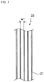
- FIG. 1 is a schematic half cross-sectional view illustrating a pneumatic tire according to one preferred embodiment of the present invention.
- An illustrated tire 10 includes: a tread portion 11 which forms a ground-contact portion; a pair of side wall portions 12 which continuously extend inward in the tire radial direction on the respective sides of the tread portion 11; and bead portions 13 which continuously extend on the inner circumferential side of each side wall portion 12.
- the tread portion 11, the side wall portions 12 and the bead portions 13 are reinforced with a carcass 14 which includes a single carcass layer toroidally extending from one bead portion 13 to the other bead portion 13.
- the tread portion 11 is reinforced with a belt 15 which includes at least one belt layer (two belt layers, which are a first belt layer 15a and a second belt layer 15b, in the illustrated example) arranged on the tire radial-direction outer side of the carcass 14 in a crown region.
- the carcass 14 may be composed of plural carcass layers, and an organic fiber cord extending in a direction substantially perpendicular to the tire circumferential direction, for example, at an angle of 70° to 90°, can be suitably used. In the belt 15, the cord angle can be 30° or smaller with respect to the tire circumferential direction.
- the belt 15 includes a belt layer (monofilament belt layer; two belt layers 15a and 15b in the illustrated example) in which a reinforcing element containing plural metal filaments aligned in a single row without being twisted together is embedded in an elastomer.
- a reinforcing element containing plural metal filaments aligned in a single row without being twisted together is embedded in an elastomer.
- the belt layer(s) can be reduced in thickness as compared to a case where a metal cord obtained by twisting metal filaments together is used as the reinforcing element.
- all of the belt layers constituting the belt 15 may be monofilament belt layers, or some of the belt layers may be monofilament belt layers.
- a known reinforcing element such as a metal cord obtained by twisting metal filaments together can be used in other belt layers.
- the metal filaments in the monofilament belt layers be substantially straight metal filaments; however, metal filaments that are two-dimensionally patterned in an undulating shape or a zigzag shape, or metal filaments that are three-dimensionally patterned in a spiral shape may be used as well.
- the term "straight metal filament” used herein refers to a metal filament that has not been intentionally patterned and thus have no substantial shape.
- FIG. 2 is a widthwise cross-sectional view illustrating a monofilament belt layer in the pneumatic tire according to one preferred embodiment of the present invention
- FIG. 3 is a plan view of a metal filament bundle illustrated in FIG. 2
- the reinforcing element is preferably a metal filament bundle 22 which includes 2 to 20 metal filaments 21.
- the metal filaments 21 constitutes preferably 2 or more, more preferably 5 or more, but preferably 20 or less, more preferably 12 or less, still more preferably 10 or less, particularly preferably 9 or less metal filament bundles 22.
- five metal filaments 21 that are paralleled without being twisted together constitute each metal filament bundle 22.
- BES belt edge separation
- each metal filament bundle 22 an elastomer 23 hardly infiltrates between adjacent filaments 21 that are in close contact with each other, and this leads to the generation of a non-elastomer-coated region where filaments are not coated with the elastomer 23. Accordingly, when the metal filament bundle 22 obtained by bundling the metal filaments 21 without twisting them together is used as the reinforcing element of the belt 15, the metal filaments 21 in such a non-elastomer-coated region are displaced from each other during tire rolling, as a result of which the in-plane rigidity of the belt 15 is reduced, and steering stability may consequently be impaired.
- the elastomer 23 it is preferred to allow the elastomer 23 to sufficiently infiltrate between adjacent metal filaments 21 so as to eliminate the above-described defects and thereby enhance the in-plane rigidity of the belt 15 and improve the steering stability.
- the elastomer coating ratio of adjacent metal filaments 21 on a widthwise side surface of the metal filament bundle 22 is preferably 10% or higher, more preferably 20% or higher, per unit length.
- the adjacent metal filaments 21 are in a state of being coated at a ratio of still more preferably 50% or higher, particularly preferably 80% or higher, most preferably 90% or higher.
- a gap w1 between the metal filaments 21 constituting the metal filament bundle 22 is preferably 0.01 mm to smaller than 0.24 mm.
- the elastomer 23 is allowed to sufficiently infiltrate therein, as a result of which the metal filament bundle 22 can undergo out-of-plane deformation when a compressive input is applied thereto, and breakage of the metal filament bundle 22 can thereby be inhibited.
- the gap w1 between the metal filaments 21 By controlling the gap w1 between the metal filaments 21 to be smaller than 0.24 mm, separation between the metal filaments 21 inside the metal filament bundle 22 can be inhibited.
- the elastomer 23 is allowed to sufficiently infiltrate between the metal filaments 21 inside the metal filament bundle 22.
- the gap w1 is preferably 0.03 mm to 0.20 mm, more preferably 0.03 mm to 0.18 mm.
- the metal filaments 21 have a diameter of preferably 0.15 mm to 0.40 mm, more preferably 0.18 mm or larger, still more preferably 0.20 mm or larger, but 0.35 mm or smaller.
- a sufficient effect of reducing the weight of the tire 10 can be obtained.
- a sufficient belt strength can be exerted.
- a gap w2 between metal filament bundles 22 is preferably 0.25 mm to 2.0 mm.
- BES can be inhibited in a favorable manner.
- the gap w2 is preferably 0.3 mm to 1.8 mm, more preferably 0.30 mm to 1.5 mm.
- the elastomer 23 may be any rubber, and examples of the elastomer 23 include, in addition to conventional rubbers: diene-based rubbers and hydrogenation products thereof, such as natural rubbers (NR), isoprene rubbers (IR), epoxidized natural rubbers, styrenebutadiene rubbers (SBR), butadiene rubbers (BR, high-cis BR and low-cis BR), nitrile rubbers (NBR), hydrogenated NBRs, and hydrogenated SBRs; olefin-based rubbers, such as ethylene-propylene rubbers (EPDM and EPM), maleic acid-modified ethylene-propylene rubbers (M-EPM), butyl rubbers (IIR), copolymers of isobutylene and an aromatic vinyl or diene monomer, acrylic rubbers (ACM), and ionomers; halogen-containing rubbers, such as Br-IIR, Cl-IIR, brominated isobutylene-p
- the "metal filaments 21" generally refers to wire-like metals that contain steel, namely iron, as a main component (the mass of iron exceeds 50% by mass with respect to a total mass of each metal filament), and the metal filaments 21 may consist of only iron, or may contain a metal other than iron, such as zinc, copper, aluminum, or tin.
- the surface state of the metal filaments 21 is not particularly limited, and the metal filaments 21 may take, for example, the following form. That is, for example, the surface of each metal filament 21 has N atoms in an amount of 2% by atom to 60% by atom, and a Cu/Zn ratio of 1 to 4. Further, in each metal filament 21, for example, the amount of phosphorus contained as an oxide in the filament outermost layer of 5 nm inward in the filament radial direction is 7.0% by atom or less in terms of the ratio with respect to the whole amount excluding the carbon (C) amount.
- the surfaces of the metal filaments 21 may be treated by plating.
- the type of the plating is not particularly limited, and examples thereof include zinc (Zn) plating, copper (Cu) plating, tin (Sn) plating, brass (copper-zinc (Cu-Zn)) plating, bronze (copper-tin (Cu-Sn)) plating, and ternary plating, such as copper-zinc-tin (Cu-Zn-Sn) plating and copper-zinc-cobalt (Cu-Zn-Co) plating.
- brass plating and copper-zinc-cobalt plating are preferred since a brass-plated metal filament exhibits excellent adhesion with a rubber.
- the ratio of copper and zinc (copper:zinc) is usually 60:40 to 70:30 based on mass, and the copper-zinc-cobalt plating usually contains 60 to 75% by mass of copper and 0.5 to 10% by mass of cobalt.
- the thickness of the resulting plated layer is generally 100 nm to 300 nm.
- the diameter, the tensile strength, and the cross-sectional shape of the metal filaments 21 are not particularly limited.
- metal filaments having a tensile strength of 2,500 MPa (250 kg/mm 2 ) or higher can be used as the metal filaments 21 .
- the widthwise cross-sectional shape of the metal filaments 21 is also not particularly limited and may be, for example, elliptical, rectangular, triangular, or polygonal; however, it is preferably circular.
- a wrapping filament spiral filament
- FIG. 4 is a development view illustrating a tread portion of the pneumatic tire according to one preferred embodiment of the present invention.
- the tire 10 of the present invention includes: two or more circumferential main grooves 16 (three circumferential grooves 16a, 16b, and 16c in the illustrated example) which are arranged within a width of a ground-contact surface of the tread portion 11; and land portions 17 (four land portions 17a, 17b, 17c, and 17d in the illustrated example) which are partitioned by the circumferential main grooves 16.
- widthwise sipes widthwise sipes 18a and 18b in the illustrated example
- 3D sipes three-dimensional sipes
- FIGS. 5A and 5B provide drawings illustrating depthwise cross-sectional shapes of the widthwise sipes 18a and 18b of the tire according to one preferred embodiment of the present invention, in which FIG. 5A is an extending length center portion and FIG. 5B is a tread widthwise end portion. As illustrated in FIGS.
- the widthwise sipes 18a and 18b which are 3D sipes arranged in the center land portions 17a and 17b each include: a linear portion 18aa (18ba) which extends from an opening on the surface of the tread portion 11 toward the tire radial-direction inner side; and a bent portion 18ab (18bb) which extends from a tire radial-direction inner end of the linear portion 18aa (18ba) toward the tire radial-direction inner side while bending in the tire circumferential direction.
- a linear shortest section where the length of the linear portion 18aa (18ba) is the shortest exists in the extending length center portion of each widthwise sipe 18a (18b), and the length of the linear portion 18aa (18ba) increases from this linear shortest section toward at least one of the tread widthwise end portions, preferably both of the tread widthwise end portions.
- the shortest section of the linear portion 18aa (18ba) has a certain width, and the length of the linear portion 18aa (18ba) may gradually increase from one end of this width toward a tread widthwise end portion of the widthwise sipe 18a (18b).
- the length of the linear portion 18aa (18ba) may be constant.
- the linear portions 18aa and 18ba have a relatively short length in the depth direction; therefore, the amount of contact between the sipe wall surfaces can be increased, and an effect of the sipe wall surfaces engaging with each other can be enhanced.
- the rigidity of the land portions 17a and 17b can be increased, so that the wear resistance of the tire can be improved.
- the bent portions 18ab and 18bb of the widthwise sipes 18a and 18b each have two or more peaks in the extending length center portion, and that the number of the peaks in the tread widthwise end portions be less than the number of the peaks in the extending length center portion.
- the reason for this is because, as a result thereof, the amount of contact between the sipe wall surfaces can be increased and an effect of the sipe wall surfaces engaging with each other can be further enhanced, so that the wear resistance of the tire can be further improved.
- the illustrated tire 10 of the present invention includes an extending length center portion that has four peaks and a tread widthwise end portion that has three peaks; however, various modifications can be made as long as the number of the peaks does not increase from the extending length center portion toward the tread widthwise end portion.
- the extending length center portion may be further divided into two regions to form a region having, for example, 5 peaks, and a region having, for example, 4 peaks (the region having 5 peaks is a region further on the extending length center side), and the tread widthwise end portion may be further divided into two regions to form a region having, for example, 3 peaks, and a region having, for example, 2 peaks (the region having 3 peaks is a region further on the extending length center side).
- the amplitude within the extending length center portion vary such that it is larger on the bottom side than on the opening side. The reason for this is because, as a result thereof, the amount of contact between the sipe wall surfaces can be increased and an effect of the sipe wall surfaces engaging with each other can be further enhanced, so that the wear resistance of the tire can be further improved.
- the amplitude gradually increases from the opening side toward the bottom side; however, the amplitude is not limited to this mode as long as it does not decrease from the opening side toward the bottom side.
- a region having a constant first amplitude may be formed on the opening side, and a region having a constant second amplitude larger than the first amplitude may be formed further on the bottom side.
- the amplitude is preferably constant.
- plural widthwise sipes 18a and 18b are arranged along the tread circumferential direction, and a ratio lid between a sipe gap 1 of adjacent widthwise sipes 18a and 18b in the tread circumferential direction and a sipe depth d preferably satisfies a relationship represented by the following equation: 2 ⁇ l / d ⁇ 4 .
- the ratio lid By controlling the ratio lid to be 2 or higher, the rigidity of the block pieces partitioned by the widthwise sipes 18a and 18b can be secured to ensure wear resistance. Meanwhile, by controlling the ratio lid to be 4 or lower, the number of the sipes can be secured to ensure the wet performance.
- a ratio Wc/Dc in the center land portions 17a and 17b between a width Wc in the tread width direction and a tread gauge Dc preferably satisfies a relationship represented by the following equation: Wc / Dc ⁇ 3 .
- a ratio Ws/Ds in the shoulder land portions 17c and 17d between a width Ws in the tread width direction and a tread gauge Ds preferably satisfies a relationship represented by the following equation: Ws / Ds ⁇ 5 .
- the tread gauge Dc of the center land portions 17a and 17b and the tread gauge Ds of the shoulder land portions 17c and 17d are both preferably 8.5 mm or less, more preferably 6.0 mm or less. This is because, by controlling the Dc and the Ds in this range, the rigidity of the center land portions 17a and 17b as well as the rigidity of the shoulder land portions 17c and 17d are ensured, so that wear resistance can be further improved.
- the above-described 3D sipes only need to be arranged in at least one of the center land portions; however, for example, as illustrated, the 3D sipes may be arranged in all of the center land portions, and the widthwise sipes 18c and 18d of the shoulder land portions 17c and 17d may also be 3D sipes having the above-described structure.
- the center land portions and the shoulder land portions linear sipes that are different from the 3D sipes having the above-described structure and have no bent portion in the depth direction may be arranged as well.
- these 3D sipes having the above-described structure and sipes that are linear in the depth direction may be arranged in plural numbers at predetermined pitch intervals along the tread circumferential direction.
- the width of the circumferential main grooves 16 is not particularly limited, and may be 5 to 20 mm. Further the depth (maximum depth) of the circumferential main grooves 16 is preferably 6.5 mm or less, more preferably 6.0 mm or less. The reason for these is because the rigidity of the land portions 17 is thereby ensured, so that wear resistance can be further improved. In consideration of the drainage performance, the depth (maximum depth) of the circumferential main grooves 16 is preferably 5.5 mm or greater.
- the widthwise sipes 18a arranged in the center land portion 17a each include: a curved portion which extends in a curved manner from the circumferential main groove 16c positioned in a half section on one side of the tread width direction toward the tread width-direction inner side; and a linear portion which is connected to this curved portion, linearly extends inclined with respect to the tread width direction, and is connected to the circumferential main groove 16a extending on the tire equatorial plane CL.
- the tire 10 of the present invention is not limited to this configuration.
- the linear portion may be inclined at an angle of, but not particularly limited to, 15° to 50° with respect to the tread width direction.
- plural widthwise sipes 18b may be arranged at a predetermined pitch interval (in the example illustrated in FIG. 4 , at substantially the same pitch interval as the widthwise sipes 18a) along the tread circumferential direction.
- the widthwise sipes 18b linearly extend inclined with respect to the tread width direction; however, the tire 10 of the present invention is not limited to this configuration.
- the widthwise sipes 18b may be inclined at an angle of, but not particularly limited to, 15° to 50° with respect to the tread width direction.
- a widthwise groove 19a which extends inclined with respect to the tread width direction from a tread edge TE toward the tread width-direction inner side and terminates within the shoulder land portion 17c may be arranged.
- the shoulder land portion 17c includes a widthwise sipe 18c which is in communication with the circumferential main groove 16c and extends inclined with respect to the tread width direction from the end of the widthwise groove 19a toward the tread width-direction inner side.
- the widthwise groove 19a and the widthwise sipe 18c may each be arranged in a plural number at a predetermined pitch interval (in the illustrated example, at a pitch interval twice as large as that of the widthwise sipes 18a) along the tread circumferential direction. These widthwise grooves 19a and widthwise sipes 18c may be inclined at an angle of, but not particularly limited to, 0° to 20° with respect to the tread width direction.
- the width of the widthwise grooves 19a is not particularly limited and may be, for example, 1 to 4 mm, and the depth (maximum depth) of the widthwise grooves 19a is also not particularly limited and may be, for example, 3 to 5 mm.
- the widthwise grooves 19a terminate within the shoulder land portion 17c without communicating with the circumferential main groove 16c, and the pitch interval along the tread circumferential direction is set larger than in the pitch interval in the center land portions 17a and 17b where only the widthwise sipes 18a and 18b are arranged, whereby the rigidity of the shoulder land portion 17c is ensured and a difference in rigidity between the shoulder land portion 17c and the center land portions 17a and 17b having no widthwise groove is reduced, so that wear resistance and uneven wear resistance are ensured.
- the shoulder land portion 17d includes a widthwise groove 19b which extends inclined with respect to the tread width direction from the tread edge TE toward the tread width-direction inner side and terminates within the shoulder land portion 17d.
- the shoulder land portion 17d includes a widthwise sipe 18d which is in communication with the circumferential main groove 16b and extends inclined with respect to the tread width direction from the tread edge TE toward the tread width-direction inner side.
- the widthwise groove 19b and the widthwise sipe 18d are arranged in plural numbers alternately to each other in the tread circumferential direction at a predetermined pitch interval (in the illustrated example, at substantially the same pitch interval as the widthwise sipes 18a).
- widthwise grooves 19b and the widthwise sipes 18d may be inclined at an angle of 0° to 20° with respect to the tread width direction.
- the width of the widthwise grooves 19b is not particularly limited and may be, for example, 1 to 4 mm, and the depth (maximum depth) of the widthwise grooves 19b is also not particularly limited and may be, for example, 3 to 5 mm.
- the widthwise grooves 19b terminate within the land portion 17d without communicating with the circumferential main groove 16b, and the widthwise grooves 19b and the widthwise sipes 18d are arranged alternately along the tread circumferential direction, whereby the rigidity of the shoulder land portion 17d is ensured and a difference in rigidity between the shoulder land portion 17d and the center land portions 17a and 17b having no widthwise groove 19b is reduced, so that wear resistance and uneven wear resistance are ensured.
- the linear portions 18aa and 18ba of the widthwise sipes 18a and 18b may have an increasing length along the depth direction from each extending length center portion toward both of the tread widthwise end portions; however, the length of the widthwise sipes 18a and 18b in the depth direction may increase from the respective extending length center portions of the widthwise sipes 18a and 18b to only either one of the tread widthwise end portions.
- the widthwise sipes 18a and 18b extend across the land portions 17a and 17b, respectively; however, the widthwise sipes 18a and 18b may terminate inside the land portions 17a and 17b, respectively.
- the widthwise sipes 18a and 18b may extend in various shapes, such as a linear shape, a curved shape, and a zigzag shape, along the tread width direction.
- the tire of the present invention has been described thus far, and the tire 10 of the present invention is not particularly limited, except for the structure of the belt 15 and the structure of the tread portion 11.
- a belt reinforcing layer may be arranged on the tire radial-direction outer side of the belt 15, and another reinforcing member may be used as well.
- a gas filled into the tire 10 of the present invention normal air or an air having an adjusted oxygen partial pressure, as well as an inert gas such as nitrogen, argon or helium, can be used.
- the tire 10 of the present invention can be suitably used as a tire of a passenger vehicle, or a tire of a truck or a bus.
- Reinforcing elements having a structure conforming to the respective conditions shown in Table 1 below were prepared using steel filaments.
- the thus obtained reinforcing elements were each coated from both above and below with a rubber-made sheet of about 0.5 mm in thickness, and the resultants were vulcanized at 160°C for 20 minutes to produce rubber-steel cord composites to be used in belt layers.
- a coating rubber was prepared by blending and kneading in accordance with a conventional method.
- the in-plane rigidity was evaluated as an index of steering stability.
- the belt angle was set at ⁇ 28° with respect to the tire circumferential direction.
- a jig was set on each of two spots underneath and one spot on top of each intersecting belt layer sample, and a load applied to the sample when the jig was pressed at one spot on top was evaluated as the in-plane rigidity.
- Table 1 in terms of index values, taking the value of Comparative Example as 100. It is noted here that the evaluation of the belt in-plane rigidity serves as an indicator relating to steering stability.
- Tires of the type illustrated in FIG. 1 were produced using the respective rubber-steel cord composites as intersecting belt layers, and the wear resistance was evaluated in accordance with the below-described procedure.
- the belt angle was ⁇ 28° with respect to the tire circumferential direction.
- the tread portion 11 had the same configuration as illustrated in the development view of FIG. 4 , and sipes having the structure shown in Table 1 were arranged in all of the land portions. The conditions of the sipes are as shown in Table 1.
- the present invention can further improve wear resistance while improving lightweightness and steering stability.
Landscapes
- Engineering & Computer Science (AREA)
- Mechanical Engineering (AREA)
- Tires In General (AREA)
Description
- The present invention relates a pneumatic tire (hereinafter, also simply referred to as "tire"), more particularly a pneumatic tire in which metal monofilaments are used in a belt layer to further improve wear resistance while improving lightweightness and steering stability.
- Generally, inside a tire that requires strength, a carcass that includes reinforcing cords embedded along the meridian direction of a ring-shaped tire main body is arranged, and a belt layer is arranged on the tire radial-direction outer side of the carcass. This belt layer is usually formed using an elastomer-metal cord composite obtained by coating a metal cord such as a steel cord with an elastomer, and imparts the tire with load resistance, traction resistance, and the like.
- In recent years, there is an increasing demand for weight reduction of tires for the purpose of improving the fuel efficiency of automobiles. As a means for reducing the tire weight, metal cords for belt reinforcement have been drawing attention, and a large number of technologies for using metal filaments as a belt cord without twisting have been disclosed. For example, Patent Document 1 discloses: a steel cord for tire reinforcement, in which the periphery of a steel cord body composed of a single monofilament is coated with a thermoplastic elastomer composition obtained by dispersing an elastomer in a thermoplastic resin; and a tire including the same. Further, Patent Document 2 discloses a pneumatic radial tire including a steel cord in a belt layer of the tire, in which steel cord two to six main filaments of the same diameter are arranged parallel without being twisted together in such a manner to constitute a single layer as a main filament bundle, and a single straight steel filament of a smaller diameter than the main filaments is wound around the main filament bundle as a wrapping filament. Attention is also drawn to the disclosures of
JPH04-95506A US2016/114630A1 . -
- [Patent Document 1]
JP2010-053495A - [Patent Document 2]
JP2012-106570A - When metal monofilaments are used as a reinforcing element of a belt layer, the belt weight is reduced and the in-plane rigidity of the belt layer is increased at the same time, so that the steering stability is improved. However, with regard to the wear resistance required as a tire performance, a further improvement is demanded at present.
- Therefore, an object of the present invention is to provide a pneumatic tire in which metal monofilaments are used in a belt layer to further improve wear resistance while improving lightweightness and steering stability.
- The present inventor intensively studied to solve the above-described problems and obtained the following finding as a result. That is, the present inventor discovered that the above-described problems can be solved by not only using metal monofilaments in a belt layer to improve lightweightness and steering stability but also arranging widthwise sipes having a predetermined structure at predetermined positions of a tread portion, thereby completing the present invention.
- That is, the pneumatic tire of the present invention is a pneumatic tire which includes a belt including at least one belt layer on a tire radial-direction inner side of a tread portion, the pneumatic tire being characterized in that:
- the belt includes a belt layer in which a reinforcing element containing plural metal filaments aligned in a single row without being twisted together is embedded in an elastomer;
- the tread portion includes two or more circumferential main grooves arranged within a width of a ground-contact surface, and land portions partitioned by the circumferential main grooves;
- when two land portions on respective tread width-direction outer sides are defined as shoulder land portions while land portions on a tread width-direction inner side than the shoulder land portions are defined as center land portions, a widthwise sipe extending in the tread width direction is arranged in at least one of the center land portions;
- the widthwise sipe includes a linear portion linearly extending from the surface of the tread portion toward the tire radial-direction inner side, and a bent portion extending from a tire radial-direction inner end of the linear portion toward the tire radial-direction inner side while bending in a tire circumferential direction;
- a linear shortest section where the length of the linear portion is the shortest exists in an extending length center portion of the widthwise sipe; and
- the length of the linear portion increases from the linear shortest section toward at least one of tread widthwise end portions.
- The "extending length center portion" of the widthwise sipe means a region of 60% in the center of the extending length of the widthwise sipe, and the "tread widthwise end portions" of the widthwise sipe means regions of 20% on the respective ends of the extending length of the widthwise sipe. Further, the term "widthwise" as used in "widthwise sipe" is defined as a direction in a range of ±50° with respect to the tread width direction.
- In the tire of the present invention, the above-described reinforcing element is preferably a metal filament bundle including 2 to 20 metal filaments. Further, in the tire of the present invention, a gap w1 between the metal filaments in the metal filament bundle is preferably 0.01 mm to 0.24 mm. Still further, in the tire of the present invention, the metal filaments preferably have a diameter of 0.15 mm to 0.40 mm. Yet still further, in the tire of the present invention, a gap w2 between adjacent metal filament bundles is preferably 0.25 mm to 2.0 mm.
- In the tire of the present invention, it is preferred that the bent portion have two or more peaks in the extending length center portion of the widthwise sipe, and that the number of peaks in the tread widthwise end portions be less than the number of the peaks in the extending length center portion. In the tire of the present invention, it is also preferred that an amplitude of the bent portion vary in the extending length center portion of the widthwise sipe such that the amplitude is larger on a bottom side than on an opening side, and that the amplitude be constant in the tread widthwise end portions of the widthwise sipe. Further, in the tire of the present invention, it is preferred that the widthwise sipe be arranged in a plural number along a tread circumferential direction, and that a ratio lid between a sipe gap 1 of adjacent widthwise sipes in the tread circumferential direction and a sipe depth d of the widthwise sipes satisfy a relationship represented by the following equation:

- Still further, in the tire of the present invention, it is preferred that, in the center land portions, a ratio Wc/Dc between a width Wc in the tread width direction and a tread gauge Dc satisfy a relationship represented by the following equation:

- Yet still further, in the tire of the present invention, it is preferred that, in the shoulder land portions, a ratio Ws/Ds between a width Ws in the tread width direction and a tread gauge Ds satisfy a relationship represented by the following equation:

- Yet still further, in the tire of the present invention, it is preferred that the tread gauge Dc of the center land portions and the tread gauge Ds of the shoulder land portions be both 8.5 mm or less.
- According to the present invention, a pneumatic tire in which metal monofilaments are used in a belt layer to further improve wear resistance while improving lightweightness and steering stability can be provided.
-
- [
FIG. 1] FIG. 1 is a half cross-sectional view illustrating a pneumatic tire according to one preferred embodiment of the present invention. - [
FIG. 2] FIG. 2 is a widthwise cross-sectional view illustrating a monofilament belt layer in the pneumatic tire according to one preferred embodiment of the present invention. - [
FIG. 3] FIG. 3 is a plan view of a metal filament bundle illustrated inFIG. 2 . - [
FIG. 4] FIG. 4 is a development view illustrating a tread portion of the pneumatic tire according to one preferred embodiment of the present invention. - [
FIG. 5 ]FIGS. 5A and5B provide drawings illustrating depthwise cross-sectional shapes ofwidthwise sipes FIG. 5A is an extending length center portion andFIG. 5B is a tread widthwise end portion. - The pneumatic tire of the present invention will now be described in detail referring to the drawings.
FIG. 1 is a schematic half cross-sectional view illustrating a pneumatic tire according to one preferred embodiment of the present invention. An illustratedtire 10 includes: atread portion 11 which forms a ground-contact portion; a pair ofside wall portions 12 which continuously extend inward in the tire radial direction on the respective sides of thetread portion 11; and beadportions 13 which continuously extend on the inner circumferential side of eachside wall portion 12. - In the illustrated
tire 10, thetread portion 11, theside wall portions 12 and thebead portions 13 are reinforced with acarcass 14 which includes a single carcass layer toroidally extending from onebead portion 13 to theother bead portion 13. In addition, thetread portion 11 is reinforced with abelt 15 which includes at least one belt layer (two belt layers, which are afirst belt layer 15a and asecond belt layer 15b, in the illustrated example) arranged on the tire radial-direction outer side of thecarcass 14 in a crown region. It is noted here that thecarcass 14 may be composed of plural carcass layers, and an organic fiber cord extending in a direction substantially perpendicular to the tire circumferential direction, for example, at an angle of 70° to 90°, can be suitably used. In thebelt 15, the cord angle can be 30° or smaller with respect to the tire circumferential direction. - First, the
belt 15 according to the tire of the present invention will be described. In thetire 10 of the present invention, thebelt 15 includes a belt layer (monofilament belt layer; twobelt layers tire 10 of the present invention, all of the belt layers constituting thebelt 15 may be monofilament belt layers, or some of the belt layers may be monofilament belt layers. When some of the belt layers are monofilament belt layers, a known reinforcing element such as a metal cord obtained by twisting metal filaments together can be used in other belt layers. - In the
tire 10 of the present invention, it is preferred that the metal filaments in the monofilament belt layers be substantially straight metal filaments; however, metal filaments that are two-dimensionally patterned in an undulating shape or a zigzag shape, or metal filaments that are three-dimensionally patterned in a spiral shape may be used as well. The term "straight metal filament" used herein refers to a metal filament that has not been intentionally patterned and thus have no substantial shape. -
FIG. 2 is a widthwise cross-sectional view illustrating a monofilament belt layer in the pneumatic tire according to one preferred embodiment of the present invention, andFIG. 3 is a plan view of a metal filament bundle illustrated inFIG. 2 . As illustrated inFIGS. 2 and3 , in thetire 10 of the present invention, the reinforcing element is preferably ametal filament bundle 22 which includes 2 to 20metal filaments 21. Themetal filaments 21 constitutes preferably 2 or more, more preferably 5 or more, but preferably 20 or less, more preferably 12 or less, still more preferably 10 or less, particularly preferably 9 or less metal filament bundles 22. In the illustrated example, fivemetal filaments 21 that are paralleled without being twisted together constitute eachmetal filament bundle 22. By bundling themetal filaments 21 in this manner, a sufficient distance w2 between metal filament bundles 22 can be ensured; therefore, belt edge separation (BES), which is propagation of rubber peeling between adjacent metal filament bundles 22 that starts at the ends of the metal filament bundles 22 on the belt widthwise edges, can be inhibited while reducing the weight through a reduction in the gauge thickness of thebelt 15. - In each
metal filament bundle 22, anelastomer 23 hardly infiltrates betweenadjacent filaments 21 that are in close contact with each other, and this leads to the generation of a non-elastomer-coated region where filaments are not coated with theelastomer 23. Accordingly, when themetal filament bundle 22 obtained by bundling themetal filaments 21 without twisting them together is used as the reinforcing element of thebelt 15, themetal filaments 21 in such a non-elastomer-coated region are displaced from each other during tire rolling, as a result of which the in-plane rigidity of thebelt 15 is reduced, and steering stability may consequently be impaired. Therefore, in thetire 10 of the present invention, it is preferred to allow theelastomer 23 to sufficiently infiltrate betweenadjacent metal filaments 21 so as to eliminate the above-described defects and thereby enhance the in-plane rigidity of thebelt 15 and improve the steering stability. - In the
tire 10 of the present invention, in order to eliminate the presence of a continuous non-elastomer-coated region betweenadjacent metal filaments 21 in themetal filament bundle 22 so as not only to ensure a corrosion propagation resistance but also to improve the in-plane rigidity of thebelt 15 and thereby obtain a good steering stabilityimproving effect, the elastomer coating ratio ofadjacent metal filaments 21 on a widthwise side surface of themetal filament bundle 22 is preferably 10% or higher, more preferably 20% or higher, per unit length. Theadjacent metal filaments 21 are in a state of being coated at a ratio of still more preferably 50% or higher, particularly preferably 80% or higher, most preferably 90% or higher. - Accordingly, in the
tire 10 of the present invention, a gap w1 between themetal filaments 21 constituting themetal filament bundle 22 is preferably 0.01 mm to smaller than 0.24 mm. By arranging the gap w1 in this range betweenadjacent metal filaments 21, theelastomer 23 is allowed to sufficiently infiltrate therein, as a result of which themetal filament bundle 22 can undergo out-of-plane deformation when a compressive input is applied thereto, and breakage of themetal filament bundle 22 can thereby be inhibited. By controlling the gap w1 between themetal filaments 21 to be smaller than 0.24 mm, separation between themetal filaments 21 inside themetal filament bundle 22 can be inhibited. Meanwhile, by controlling the gap w1 between themetal filaments 21 to be 0.01 mm or larger, theelastomer 23 is allowed to sufficiently infiltrate between themetal filaments 21 inside themetal filament bundle 22. The gap w1 is preferably 0.03 mm to 0.20 mm, more preferably 0.03 mm to 0.18 mm. - Further, in the
tire 10 of the present invention, themetal filaments 21 have a diameter of preferably 0.15 mm to 0.40 mm, more preferably 0.18 mm or larger, still more preferably 0.20 mm or larger, but 0.35 mm or smaller. By controlling the diameter of themetal filaments 21 to be 0.40 mm or smaller, a sufficient effect of reducing the weight of thetire 10 can be obtained. Meanwhile, by controlling the diameter of themetal filaments 21 to be 0.15 mm or larger, a sufficient belt strength can be exerted. - Moreover, in the
tire 10 of the present invention, a gap w2 between metal filament bundles 22 is preferably 0.25 mm to 2.0 mm. By controlling the gap w2 between metal filament bundles 22 to be 0.25 mm or larger, BES can be inhibited in a favorable manner. Meanwhile, by controlling the gap w2 between metal filament bundles 22 to be 2.0 mm or smaller, good rigidity of thebelt 15 can be maintained. The gap w2 is preferably 0.3 mm to 1.8 mm, more preferably 0.30 mm to 1.5 mm. - The elastomer 23 may be any rubber, and examples of the elastomer 23 include, in addition to conventional rubbers: diene-based rubbers and hydrogenation products thereof, such as natural rubbers (NR), isoprene rubbers (IR), epoxidized natural rubbers, styrenebutadiene rubbers (SBR), butadiene rubbers (BR, high-cis BR and low-cis BR), nitrile rubbers (NBR), hydrogenated NBRs, and hydrogenated SBRs; olefin-based rubbers, such as ethylene-propylene rubbers (EPDM and EPM), maleic acid-modified ethylene-propylene rubbers (M-EPM), butyl rubbers (IIR), copolymers of isobutylene and an aromatic vinyl or diene monomer, acrylic rubbers (ACM), and ionomers; halogen-containing rubbers, such as Br-IIR, Cl-IIR, brominated isobutylene-p-methylstyrene copolymers (Br-IPMS), chloroprene rubbers (CR), hydrin rubbers (CHR), chlorosulfonated polyethylene rubbers (CSM), chlorinated polyethylene rubbers (CM), and maleic acid-modified chlorinated polyethylene rubbers (M-CM); silicone rubbers, such as methyl vinyl silicone rubber, dimethyl silicone rubber, and methylphenyl vinyl silicone rubber; sulfur-containing rubbers, such as polysulfide rubbers; fluororubbers, such as vinylidene fluoride-based rubbers, fluorine-containing vinyl etherbased rubbers, tetrafluoroethylene-propylene-based rubbers, fluorine-containing siliconebased rubbers, and fluorine-containing phosphazene-based rubbers; and thermoplastic elastomers, such as styrene-based elastomers, olefin-based elastomers, ester-based elastomers, urethane-based elastomers, and polyamide-based elastomers.
- In the
tire 10 of the present invention, the "metal filaments 21" generally refers to wire-like metals that contain steel, namely iron, as a main component (the mass of iron exceeds 50% by mass with respect to a total mass of each metal filament), and themetal filaments 21 may consist of only iron, or may contain a metal other than iron, such as zinc, copper, aluminum, or tin. - In the
tire 10 of the present invention, the surface state of themetal filaments 21 is not particularly limited, and themetal filaments 21 may take, for example, the following form. That is, for example, the surface of eachmetal filament 21 has N atoms in an amount of 2% by atom to 60% by atom, and a Cu/Zn ratio of 1 to 4. Further, in eachmetal filament 21, for example, the amount of phosphorus contained as an oxide in the filament outermost layer of 5 nm inward in the filament radial direction is 7.0% by atom or less in terms of the ratio with respect to the whole amount excluding the carbon (C) amount. - In the
tire 10 of the present invention, the surfaces of themetal filaments 21 may be treated by plating. The type of the plating is not particularly limited, and examples thereof include zinc (Zn) plating, copper (Cu) plating, tin (Sn) plating, brass (copper-zinc (Cu-Zn)) plating, bronze (copper-tin (Cu-Sn)) plating, and ternary plating, such as copper-zinc-tin (Cu-Zn-Sn) plating and copper-zinc-cobalt (Cu-Zn-Co) plating. Thereamong, brass plating and copper-zinc-cobalt plating are preferred since a brass-plated metal filament exhibits excellent adhesion with a rubber. In the brass plating, the ratio of copper and zinc (copper:zinc) is usually 60:40 to 70:30 based on mass, and the copper-zinc-cobalt plating usually contains 60 to 75% by mass of copper and 0.5 to 10% by mass of cobalt. The thickness of the resulting plated layer is generally 100 nm to 300 nm. - Further, in the
tire 10 of the present invention, the diameter, the tensile strength, and the cross-sectional shape of themetal filaments 21 are not particularly limited. For example, as themetal filaments 21, metal filaments having a tensile strength of 2,500 MPa (250 kg/mm2) or higher can be used. The widthwise cross-sectional shape of themetal filaments 21 is also not particularly limited and may be, for example, elliptical, rectangular, triangular, or polygonal; however, it is preferably circular. In thetire 10 of the present invention, a wrapping filament (spiral filament) may be used as well when it is necessary to restrain themetal filament bundle 22. - Next, the
tread portion 11 according to thetire 10 of the present invention will be described.FIG. 4 is a development view illustrating a tread portion of the pneumatic tire according to one preferred embodiment of the present invention. As illustrated, thetire 10 of the present invention includes: two or more circumferential main grooves 16 (threecircumferential grooves tread portion 11; and land portions 17 (fourland portions shoulder land portions center land portions sipes center land portions - The
widthwise sipes FIGS. 5A and5B provide drawings illustrating depthwise cross-sectional shapes of thewidthwise sipes FIG. 5A is an extending length center portion andFIG. 5B is a tread widthwise end portion. As illustrated inFIGS. 5A and5B , thewidthwise sipes center land portions tread portion 11 toward the tire radial-direction inner side; and a bent portion 18ab (18bb) which extends from a tire radial-direction inner end of the linear portion 18aa (18ba) toward the tire radial-direction inner side while bending in the tire circumferential direction. - Further, in the
tire 10 of the present invention, a linear shortest section where the length of the linear portion 18aa (18ba) is the shortest exists in the extending length center portion of eachwidthwise sipe 18a (18b), and the length of the linear portion 18aa (18ba) increases from this linear shortest section toward at least one of the tread widthwise end portions, preferably both of the tread widthwise end portions. For example, the shortest section of the linear portion 18aa (18ba) has a certain width, and the length of the linear portion 18aa (18ba) may gradually increase from one end of this width toward a tread widthwise end portion of thewidthwise sipe 18a (18b). Further, in the tread widthwise end portion, the length of the linear portion 18aa (18ba) may be constant. The feature that "a linear shortest section where the length of the linear portion is the shortest exists in the extending length center portion of each widthwise sipe, and the length of the linear portion increases from this linear shortest section toward the tread widthwise end portion(s)" means that thewidthwise sipes - According to the
tire 10 of the present invention, in the extending length center portions of thewidthwise sipes widthwise sipes land portions - In the
tire 10 of the present invention, at a depthwise cross-section, it is preferred that the bent portions 18ab and 18bb of thewidthwise sipes - The illustrated
tire 10 of the present invention includes an extending length center portion that has four peaks and a tread widthwise end portion that has three peaks; however, various modifications can be made as long as the number of the peaks does not increase from the extending length center portion toward the tread widthwise end portion. As one example, the extending length center portion may be further divided into two regions to form a region having, for example, 5 peaks, and a region having, for example, 4 peaks (the region having 5 peaks is a region further on the extending length center side), and the tread widthwise end portion may be further divided into two regions to form a region having, for example, 3 peaks, and a region having, for example, 2 peaks (the region having 3 peaks is a region further on the extending length center side). - In the bent portions 18ab and 18bb of the
widthwise sipes tire 10 of the present invention, it is preferred that the amplitude within the extending length center portion vary such that it is larger on the bottom side than on the opening side. The reason for this is because, as a result thereof, the amount of contact between the sipe wall surfaces can be increased and an effect of the sipe wall surfaces engaging with each other can be further enhanced, so that the wear resistance of the tire can be further improved. - In the extending length center portions of the
widthwise sipes tire 10 of the present invention, the amplitude gradually increases from the opening side toward the bottom side; however, the amplitude is not limited to this mode as long as it does not decrease from the opening side toward the bottom side. For example, a region having a constant first amplitude may be formed on the opening side, and a region having a constant second amplitude larger than the first amplitude may be formed further on the bottom side. In the tread widthwise end portions of thewidthwise sipes - In the
tire 10 of the present invention, pluralwidthwise sipes widthwise sipes 
- By controlling the ratio lid to be 2 or higher, the rigidity of the block pieces partitioned by the
widthwise sipes - Further, in the
tire 10 of the present invention, a ratio Wc/Dc in thecenter land portions 
- This is because, by controlling the ratio Wc/Dc to be 3 or higher, the rigidity of the
center land portions - Moreover, in the
tire 10 of the present invention, a ratio Ws/Ds in theshoulder land portions 
- This is because, by controlling the ratio Ws/Ds to be 5 or higher, the rigidity of the
shoulder land portions - In the
tire 10 of the present invention, the tread gauge Dc of thecenter land portions shoulder land portions center land portions shoulder land portions - In the
tread portion 11 of thetire 10 of the present invention, the above-described 3D sipes only need to be arranged in at least one of the center land portions; however, for example, as illustrated, the 3D sipes may be arranged in all of the center land portions, and thewidthwise sipes shoulder land portions - In the
tire 10 of the present invention, the width of the circumferential main grooves 16 is not particularly limited, and may be 5 to 20 mm. Further the depth (maximum depth) of the circumferential main grooves 16 is preferably 6.5 mm or less, more preferably 6.0 mm or less. The reason for these is because the rigidity of the land portions 17 is thereby ensured, so that wear resistance can be further improved. In consideration of the drainage performance, the depth (maximum depth) of the circumferential main grooves 16 is preferably 5.5 mm or greater. - As illustrated in
FIG. 4 , in a plan view of thetread portion 11, thewidthwise sipes 18a arranged in thecenter land portion 17a each include: a curved portion which extends in a curved manner from the circumferentialmain groove 16c positioned in a half section on one side of the tread width direction toward the tread width-direction inner side; and a linear portion which is connected to this curved portion, linearly extends inclined with respect to the tread width direction, and is connected to the circumferentialmain groove 16a extending on the tire equatorial plane CL. However, thetire 10 of the present invention is not limited to this configuration. The linear portion may be inclined at an angle of, but not particularly limited to, 15° to 50° with respect to the tread width direction. - Further, as illustrated in
FIG. 4 , in thecenter land portion 17b, pluralwidthwise sipes 18b may be arranged at a predetermined pitch interval (in the example illustrated inFIG. 4 , at substantially the same pitch interval as thewidthwise sipes 18a) along the tread circumferential direction. In the illustrated example, thewidthwise sipes 18b linearly extend inclined with respect to the tread width direction; however, thetire 10 of the present invention is not limited to this configuration. Thewidthwise sipes 18b may be inclined at an angle of, but not particularly limited to, 15° to 50° with respect to the tread width direction. - Moreover, as illustrated in
FIG. 4 , in theshoulder land portion 17c, awidthwise groove 19a which extends inclined with respect to the tread width direction from a tread edge TE toward the tread width-direction inner side and terminates within theshoulder land portion 17c may be arranged. In addition, theshoulder land portion 17c includes awidthwise sipe 18c which is in communication with the circumferentialmain groove 16c and extends inclined with respect to the tread width direction from the end of thewidthwise groove 19a toward the tread width-direction inner side. Thewidthwise groove 19a and thewidthwise sipe 18c may each be arranged in a plural number at a predetermined pitch interval (in the illustrated example, at a pitch interval twice as large as that of thewidthwise sipes 18a) along the tread circumferential direction. Thesewidthwise grooves 19a and widthwisesipes 18c may be inclined at an angle of, but not particularly limited to, 0° to 20° with respect to the tread width direction. The width of thewidthwise grooves 19a is not particularly limited and may be, for example, 1 to 4 mm, and the depth (maximum depth) of thewidthwise grooves 19a is also not particularly limited and may be, for example, 3 to 5 mm. - As illustrated in
FIG. 4 , thewidthwise grooves 19a terminate within theshoulder land portion 17c without communicating with the circumferentialmain groove 16c, and the pitch interval along the tread circumferential direction is set larger than in the pitch interval in thecenter land portions widthwise sipes shoulder land portion 17c is ensured and a difference in rigidity between theshoulder land portion 17c and thecenter land portions - Further, as illustrated in
FIG. 4 , theshoulder land portion 17d includes awidthwise groove 19b which extends inclined with respect to the tread width direction from the tread edge TE toward the tread width-direction inner side and terminates within theshoulder land portion 17d. In addition, in the illustrated example, theshoulder land portion 17d includes awidthwise sipe 18d which is in communication with the circumferentialmain groove 16b and extends inclined with respect to the tread width direction from the tread edge TE toward the tread width-direction inner side. Thewidthwise groove 19b and thewidthwise sipe 18d are arranged in plural numbers alternately to each other in the tread circumferential direction at a predetermined pitch interval (in the illustrated example, at substantially the same pitch interval as thewidthwise sipes 18a). By this, a balance of the rigidity in theshoulder land portion 17d can be ensured. Thesewidthwise grooves 19b and thewidthwise sipes 18d may be inclined at an angle of 0° to 20° with respect to the tread width direction. The width of thewidthwise grooves 19b is not particularly limited and may be, for example, 1 to 4 mm, and the depth (maximum depth) of thewidthwise grooves 19b is also not particularly limited and may be, for example, 3 to 5 mm. - As illustrated in
FIG. 4 , thewidthwise grooves 19b terminate within theland portion 17d without communicating with the circumferentialmain groove 16b, and thewidthwise grooves 19b and thewidthwise sipes 18d are arranged alternately along the tread circumferential direction, whereby the rigidity of theshoulder land portion 17d is ensured and a difference in rigidity between theshoulder land portion 17d and thecenter land portions widthwise groove 19b is reduced, so that wear resistance and uneven wear resistance are ensured. - For example, the linear portions 18aa and 18ba of the
widthwise sipes widthwise sipes widthwise sipes tread portion 11, for example, thewidthwise sipes land portions widthwise sipes land portions widthwise sipes - The tire of the present invention has been described thus far, and the
tire 10 of the present invention is not particularly limited, except for the structure of thebelt 15 and the structure of thetread portion 11. For example, a belt reinforcing layer may be arranged on the tire radial-direction outer side of thebelt 15, and another reinforcing member may be used as well. As a gas filled into thetire 10 of the present invention, normal air or an air having an adjusted oxygen partial pressure, as well as an inert gas such as nitrogen, argon or helium, can be used. Thetire 10 of the present invention can be suitably used as a tire of a passenger vehicle, or a tire of a truck or a bus. - The present invention will now be described in more detail by way of Examples thereof.
- Reinforcing elements having a structure conforming to the respective conditions shown in Table 1 below were prepared using steel filaments. The thus obtained reinforcing elements were each coated from both above and below with a rubber-made sheet of about 0.5 mm in thickness, and the resultants were vulcanized at 160°C for 20 minutes to produce rubber-steel cord composites to be used in belt layers. A coating rubber was prepared by blending and kneading in accordance with a conventional method.
- Using intersecting belt layer samples that were prepared from each of the aboveobtained rubber-steel cord composites, the in-plane rigidity was evaluated as an index of steering stability. The belt angle was set at ±28° with respect to the tire circumferential direction. A jig was set on each of two spots underneath and one spot on top of each intersecting belt layer sample, and a load applied to the sample when the jig was pressed at one spot on top was evaluated as the in-plane rigidity. The results thereof are shown together in Table 1 in terms of index values, taking the value of Comparative Example as 100. It is noted here that the evaluation of the belt in-plane rigidity serves as an indicator relating to steering stability.
- Tires of the type illustrated in
FIG. 1 (size: 205/55R16) were produced using the respective rubber-steel cord composites as intersecting belt layers, and the wear resistance was evaluated in accordance with the below-described procedure. The belt angle was ±28° with respect to the tire circumferential direction. Thetread portion 11 had the same configuration as illustrated in the development view ofFIG. 4 , and sipes having the structure shown in Table 1 were arranged in all of the land portions. The conditions of the sipes are as shown in Table 1. - The thus obtained tires were each mounted on a rim, inflated to a predetermined internal pressure and then fitted to a vehicle, and the wear resistance was estimated when the vehicle was driven in various driving modes on an ordinary road having a dry surface. The symbols "×" and "o" in Table 1 indicate the followings.
- ×: The sipes cause a reduction in the shear rigidity of the land portions, and the wear resistance is reduced.
- ∘: An improvement in the in-plane rigidity by monofilament structure formation and an improvement in the shear rigidity of the land portions by three-dimensional sipes are likely to occur, and the wear resistance of the tire is expected to be improved.
- From Table 1, it is seen that the present invention can further improve wear resistance while improving lightweightness and steering stability.
-
- 10: pneumatic tire (tire)
- 11: tread portion
- 12: side wall portion
- 13: bead portion
- 14: carcass
- 15: belt
- 15a, 15b: belt layer
- 16: circumferential main groove
- 17: land portion
- 18: widthwise sipe
- 19: widthwise groove
- 21: metal filament
- 22: metal filament bundle
- 23: elastomer

Claims (11)
- A pneumatic tire (10), comprising a belt (15) comprising at least one belt layer (15a, 15b) on a tire radial-direction inner side of a tread portion (11),
whereinthe belt (15) comprises a belt layer (15a, 15b) in which a reinforcing element (22) comprising plural metal filaments (21) aligned in a single row without being twisted together is embedded in an elastomer,the tread portion (11) comprises: two or more circumferential main grooves (16a-16c) arranged within a width of a ground-contact surface; and land portions (17a-17d) partitioned by the circumferential main grooves (16a-16c),when two land portions (17c, 17d) on respective tread width-direction outer sides are defined as shoulder land portions (17c, 17d) while land portions (17a, 17b) on a tread width-direction inner side than the shoulder land portions (17c, 17d) are defined as center land portions (17a, 17b), a widthwise sipe (18a, 18b) extending in the tread width direction is arranged in at least one of the center land portions (17a, 17b),characterised in thatthe widthwise sipe (18a, 18b) comprises: a linear portion (18aa, 18ba) linearly extending from the surface of the tread portion (11) toward the tire radial-direction inner side; and a bent portion (18ab, 18bb) extending from a tire radial-direction inner end of the linear portion (18aa, 18ba) toward the tire radial-direction inner side while bending in a tire circumferential direction,a linear shortest section where the length of the linear portion (18aa, 18ba) is the shortest exists in an extending length center portion of the widthwise sipe (18a, 18b), andthe length of the linear portion (18aa, 18ba) increases from the linear shortest section toward at least one of tread widthwise end portions. - The pneumatic tire (10) according to claim 1, wherein the reinforcing element (22) is a metal filament bundle (22) comprising 2 to 20 metal filaments (21).
- The pneumatic tire (10) according to claim 2, wherein a gap (w1) between the metal filaments (21) in the metal filament bundle (22) is 0.01 mm to 0.24 mm.
- The pneumatic tire (10) according to any one of claims 1 to 3, wherein the metal filaments (21) have a diameter of 0.15 mm to 0.40 mm.
- The pneumatic tire (10) according to any one of claims 1 to 4, wherein a gap (w2) between adjacent metal filament bundles (22) is 0.25 mm to 2.0 mm.
- The pneumatic tire (10) according to any one of claims 1 to 5, whereinthe bent portion (18ab, 18bb) has two or more peaks in the extending length center portion of the widthwise sipe, andthe number of peaks in the tread widthwise end portions is less than the number of the peaks in the extending length center portion.
- The pneumatic tire (10) according to any one of claims 1 to 6, whereinan amplitude of the bent portion (18ab, 18bb) varies in the extending length center portion of the widthwise sipe (18a, 18b) such that the amplitude is larger on a bottom side than on an opening side, andthe amplitude is constant in the tread widthwise end portions of the widthwise sipe (18a, 18b).
- The pneumatic tire (10) according to any one of claims 1 to 7, whereinthe widthwise sipe (18a, 18b) is arranged in a plural number along a tread circumferential direction, anda ratio lid between a sipe gap 1 of adjacent widthwise sipes (18a, 18b) in the tread circumferential direction and a sipe depth d of the widthwise sipes (18a, 18b) satisfies a relationship represented by the following equation:

- The pneumatic tire (10) according to any one of claims 1 to 8, wherein, in each center land portion (17a, 17b), a ratio Wc/Dc between a width Wc of the center land portion (17a, 17b) in the tread width direction and a tread gauge Dc of the center land portion (17a, 17b) satisfies a relationship represented by the following equation:

- The pneumatic tire (10) according to any one of claims 1 to 9, wherein, in each shoulder land portion (17c, 17d), a ratio Ws/Ds between a width Ws of the shoulder land portion (17c, 17d) in the tread width direction and a tread gauge Ds of the shoulder land portion (17c, 17d) satisfies a relationship represented by the following equation:

- The pneumatic tire (10) according to any one of claims 1 to 10, wherein the tread gauge Dc of the center land portions (17a, 17b) and the tread gauge Ds of the shoulder land portions (17c, 17d) are both 8.5 mm or less.
Applications Claiming Priority (2)
| Application Number | Priority Date | Filing Date | Title |
|---|---|---|---|
| JP2019114012A JP7199311B2 (en) | 2019-06-19 | 2019-06-19 | pneumatic tire |
| PCT/JP2019/048755 WO2020255453A1 (en) | 2019-06-19 | 2019-12-12 | Pneumatic tire |
Publications (3)
| Publication Number | Publication Date |
|---|---|
| EP3988328A1 EP3988328A1 (en) | 2022-04-27 |
| EP3988328A4 EP3988328A4 (en) | 2023-07-05 |
| EP3988328B1 true EP3988328B1 (en) | 2024-08-14 |
Family
ID=73994709
Family Applications (1)
| Application Number | Title | Priority Date | Filing Date |
|---|---|---|---|
| EP19933946.6A Active EP3988328B1 (en) | 2019-06-19 | 2019-12-12 | Pneumatic tire |
Country Status (5)
| Country | Link |
|---|---|
| US (1) | US12128711B2 (en) |
| EP (1) | EP3988328B1 (en) |
| JP (1) | JP7199311B2 (en) |
| CN (1) | CN113993720B (en) |
| WO (1) | WO2020255453A1 (en) |
Families Citing this family (1)
| Publication number | Priority date | Publication date | Assignee | Title |
|---|---|---|---|---|
| WO2023095471A1 (en) * | 2021-11-24 | 2023-06-01 | 株式会社ブリヂストン | Tire |
Family Cites Families (37)
| Publication number | Priority date | Publication date | Assignee | Title |
|---|---|---|---|---|
| US2302027A (en) * | 1940-08-09 | 1942-11-17 | Us Rubber Co | Pneumatic tire |
| JPH02270608A (en) * | 1989-04-13 | 1990-11-05 | Bridgestone Corp | Pneumatic tire for heavy load |
| JP2713807B2 (en) | 1990-08-10 | 1998-02-16 | 株式会社ブリヂストン | Radial tire |
| JP3226968B2 (en) * | 1992-07-20 | 2001-11-12 | 株式会社ブリヂストン | Pneumatic tire |
| JP3373577B2 (en) * | 1993-03-11 | 2003-02-04 | 株式会社ブリヂストン | Pneumatic radial tires with reduced outside noise |
| DE60113006T2 (en) * | 2000-05-12 | 2006-03-16 | Bridgestone Corp. | Radial tire |
| JP3648179B2 (en) | 2001-07-18 | 2005-05-18 | 住友ゴム工業株式会社 | Pneumatic tire and its vulcanization mold |
| JP2004314758A (en) * | 2003-04-15 | 2004-11-11 | Bridgestone Corp | Pneumatic tire |
| JP4325948B2 (en) * | 2006-06-21 | 2009-09-02 | 東洋ゴム工業株式会社 | Pneumatic tire |
| JP2010053495A (en) | 2008-08-29 | 2010-03-11 | Yokohama Rubber Co Ltd:The | Steel cord for reinforcing tire, and pneumatic tire using the same |
| JP2010111354A (en) * | 2008-11-10 | 2010-05-20 | Bridgestone Corp | Tire |
| JP5192363B2 (en) * | 2008-12-18 | 2013-05-08 | 株式会社ブリヂストン | tire |
| CN101811421B (en) * | 2009-02-19 | 2012-04-18 | 正新橡胶(中国)有限公司 | Tread structure with knife slot pattern |
| RU2521455C2 (en) * | 2009-10-20 | 2014-06-27 | Бриджстоун Корпорейшн | Pneumatic tire |
| JP2011143858A (en) * | 2010-01-15 | 2011-07-28 | Bridgestone Corp | Pneumatic radial tire |
| US20130206302A1 (en) * | 2010-06-29 | 2013-08-15 | The Yokohama Rubber Co., Ltd. | Pneumatic tire |
| JP5257436B2 (en) * | 2010-10-05 | 2013-08-07 | 横浜ゴム株式会社 | Pneumatic radial tire |
| FR2966083B1 (en) * | 2010-10-14 | 2012-10-26 | Michelin Soc Tech | IMPROVEMENT TO TIRE NOISE ATTENUATOR DEVICES |
| JP5318841B2 (en) * | 2010-11-16 | 2013-10-16 | 東洋ゴム工業株式会社 | Pneumatic radial tire |
| FR2975046B1 (en) * | 2011-05-11 | 2013-06-14 | Michelin Soc Tech | COMBINING ROLLER INSERTS AND INCISIONS |
| JP2013132993A (en) * | 2011-12-26 | 2013-07-08 | Bridgestone Corp | Pneumatic tire |
| WO2013114852A1 (en) | 2012-02-01 | 2013-08-08 | 株式会社ブリヂストン | Pneumatic tire |
| JP6185696B2 (en) * | 2012-05-24 | 2017-08-23 | 株式会社ブリヂストン | Pneumatic tire |
| JP2013244811A (en) * | 2012-05-24 | 2013-12-09 | Bridgestone Corp | Pneumatic tire |
| JP2013216271A (en) * | 2012-04-11 | 2013-10-24 | Yokohama Rubber Co Ltd:The | Pneumatic tire |
| JP5953937B2 (en) * | 2012-05-24 | 2016-07-20 | 横浜ゴム株式会社 | Pneumatic radial tire for passenger cars |
| JP2015037924A (en) * | 2013-03-26 | 2015-02-26 | 横浜ゴム株式会社 | Pneumatic tire |
| JP5526266B1 (en) * | 2013-06-24 | 2014-06-18 | 株式会社ブリヂストン | Pneumatic tire |
| JP6329010B2 (en) * | 2014-06-13 | 2018-05-23 | 株式会社ブリヂストン | Pneumatic tire |
| JP6229735B2 (en) * | 2014-10-31 | 2017-11-15 | 横浜ゴム株式会社 | Heavy duty pneumatic tire |
| JP6445870B2 (en) * | 2015-01-05 | 2018-12-26 | 住友ゴム工業株式会社 | Pneumatic tire |
| JP6714985B2 (en) * | 2015-09-09 | 2020-07-01 | 株式会社ブリヂストン | tire |
| JP6554017B2 (en) * | 2015-11-05 | 2019-07-31 | Toyo Tire株式会社 | Pneumatic tire |
| JP6727015B2 (en) * | 2016-04-20 | 2020-07-22 | 株式会社ブリヂストン | Tires and tire molds |
| CN109070653B (en) | 2016-04-20 | 2020-12-01 | 株式会社普利司通 | Tire and tire mold |
| CN110494302A (en) | 2017-04-11 | 2019-11-22 | 株式会社普利司通 | Elastomer metal cord composite object and the tire for using it |
| JP2019111845A (en) * | 2017-12-20 | 2019-07-11 | 株式会社ブリヂストン | Pneumatic tire |
-
2019
- 2019-06-19 JP JP2019114012A patent/JP7199311B2/en active Active
- 2019-12-12 EP EP19933946.6A patent/EP3988328B1/en active Active
- 2019-12-12 WO PCT/JP2019/048755 patent/WO2020255453A1/en not_active Ceased
- 2019-12-12 US US17/596,284 patent/US12128711B2/en active Active
- 2019-12-12 CN CN201980097270.XA patent/CN113993720B/en active Active
Also Published As
| Publication number | Publication date |
|---|---|
| US20220227177A1 (en) | 2022-07-21 |
| EP3988328A4 (en) | 2023-07-05 |
| WO2020255453A1 (en) | 2020-12-24 |
| CN113993720B (en) | 2023-10-13 |
| CN113993720A (en) | 2022-01-28 |
| US12128711B2 (en) | 2024-10-29 |
| JP2021000857A (en) | 2021-01-07 |
| EP3988328A1 (en) | 2022-04-27 |
| JP7199311B2 (en) | 2023-01-05 |
Similar Documents
| Publication | Publication Date | Title |
|---|---|---|
| EP1386757A1 (en) | A crown reinforcement for heavy duty tires | |
| EP3611035B1 (en) | Elastomer-metal cord composite and tire using same | |
| US20210354515A1 (en) | Tire | |
| EP3868570B1 (en) | Tire | |
| EP3611034B1 (en) | Elastomer-metal cord composite and tire using same | |
| EP3988328B1 (en) | Pneumatic tire | |
| JP6683570B2 (en) | Pneumatic tire | |
| EP3868575B1 (en) | Elastomer-metal cord composite body, and tire using same | |
| JP7351846B2 (en) | Elastomer-metal cord composite and tires using the same | |
| JP2000177311A (en) | Pneumatic radial tire | |
| JPH05246206A (en) | Pneumatic tire | |
| JP2009166726A (en) | Pneumatic tire | |
| EP1001074A2 (en) | Steel cords for the reinforcement of rubber articles and pneumatic tires | |
| JP7397656B2 (en) | tire | |
| JPH0551884A (en) | Metallic cord for tire | |
| JPWO2020080440A1 (en) | Elastomer-metal cord complex and tires using it | |
| WO2020080446A1 (en) | Tire | |
| WO2020080445A1 (en) | Tire |
Legal Events
| Date | Code | Title | Description |
|---|---|---|---|
| STAA | Information on the status of an ep patent application or granted ep patent |
Free format text: STATUS: THE INTERNATIONAL PUBLICATION HAS BEEN MADE |
|
| PUAI | Public reference made under article 153(3) epc to a published international application that has entered the european phase |
Free format text: ORIGINAL CODE: 0009012 |
|
| STAA | Information on the status of an ep patent application or granted ep patent |
Free format text: STATUS: REQUEST FOR EXAMINATION WAS MADE |
|
| 17P | Request for examination filed |
Effective date: 20211208 |
|
| AK | Designated contracting states |
Kind code of ref document: A1 Designated state(s): AL AT BE BG CH CY CZ DE DK EE ES FI FR GB GR HR HU IE IS IT LI LT LU LV MC MK MT NL NO PL PT RO RS SE SI SK SM TR |
|
| DAV | Request for validation of the european patent (deleted) | ||
| DAX | Request for extension of the european patent (deleted) | ||
| A4 | Supplementary search report drawn up and despatched |
Effective date: 20230607 |
|
| RIC1 | Information provided on ipc code assigned before grant |
Ipc: B60C 11/12 20060101ALI20230601BHEP Ipc: B60C 11/03 20060101ALI20230601BHEP Ipc: B60C 11/00 20060101ALI20230601BHEP Ipc: B60C 9/20 20060101ALI20230601BHEP Ipc: B60C 9/00 20060101AFI20230601BHEP |
|
| GRAP | Despatch of communication of intention to grant a patent |
Free format text: ORIGINAL CODE: EPIDOSNIGR1 |
|
| STAA | Information on the status of an ep patent application or granted ep patent |
Free format text: STATUS: GRANT OF PATENT IS INTENDED |
|
| INTG | Intention to grant announced |
Effective date: 20240313 |
|
| P01 | Opt-out of the competence of the unified patent court (upc) registered |
Effective date: 20240327 |
|
| GRAS | Grant fee paid |
Free format text: ORIGINAL CODE: EPIDOSNIGR3 |
|
| GRAA | (expected) grant |
Free format text: ORIGINAL CODE: 0009210 |
|
| STAA | Information on the status of an ep patent application or granted ep patent |
Free format text: STATUS: THE PATENT HAS BEEN GRANTED |
|
| AK | Designated contracting states |
Kind code of ref document: B1 Designated state(s): AL AT BE BG CH CY CZ DE DK EE ES FI FR GB GR HR HU IE IS IT LI LT LU LV MC MK MT NL NO PL PT RO RS SE SI SK SM TR |
|
| REG | Reference to a national code |
Ref country code: GB Ref legal event code: FG4D |
|
| REG | Reference to a national code |
Ref country code: CH Ref legal event code: EP |
|
| REG | Reference to a national code |
Ref country code: DE Ref legal event code: R096 Ref document number: 602019057209 Country of ref document: DE |
|
| REG | Reference to a national code |
Ref country code: IE Ref legal event code: FG4D |
|
| REG | Reference to a national code |
Ref country code: LT Ref legal event code: MG9D |
|
| REG | Reference to a national code |
Ref country code: NL Ref legal event code: MP Effective date: 20240814 |
|
| PG25 | Lapsed in a contracting state [announced via postgrant information from national office to epo] |
Ref country code: NO Free format text: LAPSE BECAUSE OF FAILURE TO SUBMIT A TRANSLATION OF THE DESCRIPTION OR TO PAY THE FEE WITHIN THE PRESCRIBED TIME-LIMIT Effective date: 20241114 |
|
| REG | Reference to a national code |
Ref country code: AT Ref legal event code: MK05 Ref document number: 1712971 Country of ref document: AT Kind code of ref document: T Effective date: 20240814 |
|
| PG25 | Lapsed in a contracting state [announced via postgrant information from national office to epo] |
Ref country code: FI Free format text: LAPSE BECAUSE OF FAILURE TO SUBMIT A TRANSLATION OF THE DESCRIPTION OR TO PAY THE FEE WITHIN THE PRESCRIBED TIME-LIMIT Effective date: 20240814 Ref country code: NL Free format text: LAPSE BECAUSE OF FAILURE TO SUBMIT A TRANSLATION OF THE DESCRIPTION OR TO PAY THE FEE WITHIN THE PRESCRIBED TIME-LIMIT Effective date: 20240814 Ref country code: PL Free format text: LAPSE BECAUSE OF FAILURE TO SUBMIT A TRANSLATION OF THE DESCRIPTION OR TO PAY THE FEE WITHIN THE PRESCRIBED TIME-LIMIT Effective date: 20240814 Ref country code: GR Free format text: LAPSE BECAUSE OF FAILURE TO SUBMIT A TRANSLATION OF THE DESCRIPTION OR TO PAY THE FEE WITHIN THE PRESCRIBED TIME-LIMIT Effective date: 20241115 Ref country code: PT Free format text: LAPSE BECAUSE OF FAILURE TO SUBMIT A TRANSLATION OF THE DESCRIPTION OR TO PAY THE FEE WITHIN THE PRESCRIBED TIME-LIMIT Effective date: 20241216 |
|
| PG25 | Lapsed in a contracting state [announced via postgrant information from national office to epo] |
Ref country code: BG Free format text: LAPSE BECAUSE OF FAILURE TO SUBMIT A TRANSLATION OF THE DESCRIPTION OR TO PAY THE FEE WITHIN THE PRESCRIBED TIME-LIMIT Effective date: 20240814 |
|
| PG25 | Lapsed in a contracting state [announced via postgrant information from national office to epo] |
Ref country code: LV Free format text: LAPSE BECAUSE OF FAILURE TO SUBMIT A TRANSLATION OF THE DESCRIPTION OR TO PAY THE FEE WITHIN THE PRESCRIBED TIME-LIMIT Effective date: 20240814 |
|
| PG25 | Lapsed in a contracting state [announced via postgrant information from national office to epo] |
Ref country code: AT Free format text: LAPSE BECAUSE OF FAILURE TO SUBMIT A TRANSLATION OF THE DESCRIPTION OR TO PAY THE FEE WITHIN THE PRESCRIBED TIME-LIMIT Effective date: 20240814 Ref country code: IS Free format text: LAPSE BECAUSE OF FAILURE TO SUBMIT A TRANSLATION OF THE DESCRIPTION OR TO PAY THE FEE WITHIN THE PRESCRIBED TIME-LIMIT Effective date: 20241214 |
|
| PG25 | Lapsed in a contracting state [announced via postgrant information from national office to epo] |
Ref country code: HR Free format text: LAPSE BECAUSE OF FAILURE TO SUBMIT A TRANSLATION OF THE DESCRIPTION OR TO PAY THE FEE WITHIN THE PRESCRIBED TIME-LIMIT Effective date: 20240814 |
|
| PG25 | Lapsed in a contracting state [announced via postgrant information from national office to epo] |
Ref country code: RS Free format text: LAPSE BECAUSE OF FAILURE TO SUBMIT A TRANSLATION OF THE DESCRIPTION OR TO PAY THE FEE WITHIN THE PRESCRIBED TIME-LIMIT Effective date: 20241114 Ref country code: ES Free format text: LAPSE BECAUSE OF FAILURE TO SUBMIT A TRANSLATION OF THE DESCRIPTION OR TO PAY THE FEE WITHIN THE PRESCRIBED TIME-LIMIT Effective date: 20240814 |
|
| PG25 | Lapsed in a contracting state [announced via postgrant information from national office to epo] |
Ref country code: RS Free format text: LAPSE BECAUSE OF FAILURE TO SUBMIT A TRANSLATION OF THE DESCRIPTION OR TO PAY THE FEE WITHIN THE PRESCRIBED TIME-LIMIT Effective date: 20241114 Ref country code: PT Free format text: LAPSE BECAUSE OF FAILURE TO SUBMIT A TRANSLATION OF THE DESCRIPTION OR TO PAY THE FEE WITHIN THE PRESCRIBED TIME-LIMIT Effective date: 20241216 Ref country code: PL Free format text: LAPSE BECAUSE OF FAILURE TO SUBMIT A TRANSLATION OF THE DESCRIPTION OR TO PAY THE FEE WITHIN THE PRESCRIBED TIME-LIMIT Effective date: 20240814 Ref country code: NO Free format text: LAPSE BECAUSE OF FAILURE TO SUBMIT A TRANSLATION OF THE DESCRIPTION OR TO PAY THE FEE WITHIN THE PRESCRIBED TIME-LIMIT Effective date: 20241114 Ref country code: NL Free format text: LAPSE BECAUSE OF FAILURE TO SUBMIT A TRANSLATION OF THE DESCRIPTION OR TO PAY THE FEE WITHIN THE PRESCRIBED TIME-LIMIT Effective date: 20240814 Ref country code: LV Free format text: LAPSE BECAUSE OF FAILURE TO SUBMIT A TRANSLATION OF THE DESCRIPTION OR TO PAY THE FEE WITHIN THE PRESCRIBED TIME-LIMIT Effective date: 20240814 Ref country code: IS Free format text: LAPSE BECAUSE OF FAILURE TO SUBMIT A TRANSLATION OF THE DESCRIPTION OR TO PAY THE FEE WITHIN THE PRESCRIBED TIME-LIMIT Effective date: 20241214 Ref country code: HR Free format text: LAPSE BECAUSE OF FAILURE TO SUBMIT A TRANSLATION OF THE DESCRIPTION OR TO PAY THE FEE WITHIN THE PRESCRIBED TIME-LIMIT Effective date: 20240814 Ref country code: GR Free format text: LAPSE BECAUSE OF FAILURE TO SUBMIT A TRANSLATION OF THE DESCRIPTION OR TO PAY THE FEE WITHIN THE PRESCRIBED TIME-LIMIT Effective date: 20241115 Ref country code: FI Free format text: LAPSE BECAUSE OF FAILURE TO SUBMIT A TRANSLATION OF THE DESCRIPTION OR TO PAY THE FEE WITHIN THE PRESCRIBED TIME-LIMIT Effective date: 20240814 Ref country code: ES Free format text: LAPSE BECAUSE OF FAILURE TO SUBMIT A TRANSLATION OF THE DESCRIPTION OR TO PAY THE FEE WITHIN THE PRESCRIBED TIME-LIMIT Effective date: 20240814 Ref country code: BG Free format text: LAPSE BECAUSE OF FAILURE TO SUBMIT A TRANSLATION OF THE DESCRIPTION OR TO PAY THE FEE WITHIN THE PRESCRIBED TIME-LIMIT Effective date: 20240814 Ref country code: AT Free format text: LAPSE BECAUSE OF FAILURE TO SUBMIT A TRANSLATION OF THE DESCRIPTION OR TO PAY THE FEE WITHIN THE PRESCRIBED TIME-LIMIT Effective date: 20240814 |
|
| PG25 | Lapsed in a contracting state [announced via postgrant information from national office to epo] |
Ref country code: SM Free format text: LAPSE BECAUSE OF FAILURE TO SUBMIT A TRANSLATION OF THE DESCRIPTION OR TO PAY THE FEE WITHIN THE PRESCRIBED TIME-LIMIT Effective date: 20240814 Ref country code: RO Free format text: LAPSE BECAUSE OF FAILURE TO SUBMIT A TRANSLATION OF THE DESCRIPTION OR TO PAY THE FEE WITHIN THE PRESCRIBED TIME-LIMIT Effective date: 20240814 Ref country code: DK Free format text: LAPSE BECAUSE OF FAILURE TO SUBMIT A TRANSLATION OF THE DESCRIPTION OR TO PAY THE FEE WITHIN THE PRESCRIBED TIME-LIMIT Effective date: 20240814 |
|
| PG25 | Lapsed in a contracting state [announced via postgrant information from national office to epo] |
Ref country code: EE Free format text: LAPSE BECAUSE OF FAILURE TO SUBMIT A TRANSLATION OF THE DESCRIPTION OR TO PAY THE FEE WITHIN THE PRESCRIBED TIME-LIMIT Effective date: 20240814 |
|
| PG25 | Lapsed in a contracting state [announced via postgrant information from national office to epo] |
Ref country code: CZ Free format text: LAPSE BECAUSE OF FAILURE TO SUBMIT A TRANSLATION OF THE DESCRIPTION OR TO PAY THE FEE WITHIN THE PRESCRIBED TIME-LIMIT Effective date: 20240814 |
|
| PG25 | Lapsed in a contracting state [announced via postgrant information from national office to epo] |
Ref country code: SK Free format text: LAPSE BECAUSE OF FAILURE TO SUBMIT A TRANSLATION OF THE DESCRIPTION OR TO PAY THE FEE WITHIN THE PRESCRIBED TIME-LIMIT Effective date: 20240814 Ref country code: IT Free format text: LAPSE BECAUSE OF FAILURE TO SUBMIT A TRANSLATION OF THE DESCRIPTION OR TO PAY THE FEE WITHIN THE PRESCRIBED TIME-LIMIT Effective date: 20240814 |
|
| REG | Reference to a national code |
Ref country code: DE Ref legal event code: R097 Ref document number: 602019057209 Country of ref document: DE |
|
| PLBE | No opposition filed within time limit |
Free format text: ORIGINAL CODE: 0009261 |
|
| STAA | Information on the status of an ep patent application or granted ep patent |
Free format text: STATUS: NO OPPOSITION FILED WITHIN TIME LIMIT |
|
| PG25 | Lapsed in a contracting state [announced via postgrant information from national office to epo] |
Ref country code: MC Free format text: LAPSE BECAUSE OF FAILURE TO SUBMIT A TRANSLATION OF THE DESCRIPTION OR TO PAY THE FEE WITHIN THE PRESCRIBED TIME-LIMIT Effective date: 20240814 |
|
| 26N | No opposition filed |
Effective date: 20250515 |
|
| REG | Reference to a national code |
Ref country code: CH Ref legal event code: PL |
|
| PG25 | Lapsed in a contracting state [announced via postgrant information from national office to epo] |
Ref country code: LU Free format text: LAPSE BECAUSE OF NON-PAYMENT OF DUE FEES Effective date: 20241212 |
|
| GBPC | Gb: european patent ceased through non-payment of renewal fee |
Effective date: 20241212 |
|
| PG25 | Lapsed in a contracting state [announced via postgrant information from national office to epo] |
Ref country code: SE Free format text: LAPSE BECAUSE OF FAILURE TO SUBMIT A TRANSLATION OF THE DESCRIPTION OR TO PAY THE FEE WITHIN THE PRESCRIBED TIME-LIMIT Effective date: 20240814 |
|
| REG | Reference to a national code |
Ref country code: BE Ref legal event code: MM Effective date: 20241231 |
|
| PG25 | Lapsed in a contracting state [announced via postgrant information from national office to epo] |
Ref country code: GB Free format text: LAPSE BECAUSE OF NON-PAYMENT OF DUE FEES Effective date: 20241212 Ref country code: BE Free format text: LAPSE BECAUSE OF NON-PAYMENT OF DUE FEES Effective date: 20241231 |
|
| PG25 | Lapsed in a contracting state [announced via postgrant information from national office to epo] |
Ref country code: CH Free format text: LAPSE BECAUSE OF NON-PAYMENT OF DUE FEES Effective date: 20241231 |
|
| PG25 | Lapsed in a contracting state [announced via postgrant information from national office to epo] |
Ref country code: IE Free format text: LAPSE BECAUSE OF NON-PAYMENT OF DUE FEES Effective date: 20241212 |
|
| PGFP | Annual fee paid to national office [announced via postgrant information from national office to epo] |
Ref country code: DE Payment date: 20251211 Year of fee payment: 7 |
|
| PGFP | Annual fee paid to national office [announced via postgrant information from national office to epo] |
Ref country code: FR Payment date: 20251229 Year of fee payment: 7 |