EP3988236A1 - Method to execute a weld of an electrode of a cell which is part of a battery - Google Patents
Method to execute a weld of an electrode of a cell which is part of a battery Download PDFInfo
- Publication number
- EP3988236A1 EP3988236A1 EP21204191.7A EP21204191A EP3988236A1 EP 3988236 A1 EP3988236 A1 EP 3988236A1 EP 21204191 A EP21204191 A EP 21204191A EP 3988236 A1 EP3988236 A1 EP 3988236A1
- Authority
- EP
- European Patent Office
- Prior art keywords
- weld
- electrode
- heating
- weld pool
- execution method
- Prior art date
- Legal status (The legal status is an assumption and is not a legal conclusion. Google has not performed a legal analysis and makes no representation as to the accuracy of the status listed.)
- Granted
Links
- 238000000034 method Methods 0.000 title claims abstract description 40
- 238000010438 heat treatment Methods 0.000 claims abstract description 46
- 238000003466 welding Methods 0.000 claims abstract description 28
- 239000002184 metal Substances 0.000 claims abstract description 12
- 238000002844 melting Methods 0.000 claims abstract description 4
- 230000008018 melting Effects 0.000 claims abstract description 4
- 238000010309 melting process Methods 0.000 claims abstract description 4
- 230000003247 decreasing effect Effects 0.000 claims description 10
- 230000005855 radiation Effects 0.000 claims description 3
- 238000002604 ultrasonography Methods 0.000 claims description 2
- 238000004458 analytical method Methods 0.000 description 3
- 230000007547 defect Effects 0.000 description 1
- 230000001419 dependent effect Effects 0.000 description 1
- 230000000694 effects Effects 0.000 description 1
- 239000007788 liquid Substances 0.000 description 1
- 238000005259 measurement Methods 0.000 description 1
- 238000012544 monitoring process Methods 0.000 description 1
- 238000001931 thermography Methods 0.000 description 1
Images

Classifications
-
- B—PERFORMING OPERATIONS; TRANSPORTING
- B23—MACHINE TOOLS; METAL-WORKING NOT OTHERWISE PROVIDED FOR
- B23K—SOLDERING OR UNSOLDERING; WELDING; CLADDING OR PLATING BY SOLDERING OR WELDING; CUTTING BY APPLYING HEAT LOCALLY, e.g. FLAME CUTTING; WORKING BY LASER BEAM
- B23K31/00—Processes relevant to this subclass, specially adapted for particular articles or purposes, but not covered by only one of the preceding main groups
- B23K31/12—Processes relevant to this subclass, specially adapted for particular articles or purposes, but not covered by only one of the preceding main groups relating to investigating the properties, e.g. the weldability, of materials
- B23K31/125—Weld quality monitoring
-
- B—PERFORMING OPERATIONS; TRANSPORTING
- B23—MACHINE TOOLS; METAL-WORKING NOT OTHERWISE PROVIDED FOR
- B23K—SOLDERING OR UNSOLDERING; WELDING; CLADDING OR PLATING BY SOLDERING OR WELDING; CUTTING BY APPLYING HEAT LOCALLY, e.g. FLAME CUTTING; WORKING BY LASER BEAM
- B23K26/00—Working by laser beam, e.g. welding, cutting or boring
- B23K26/20—Bonding
- B23K26/21—Bonding by welding
- B23K26/22—Spot welding
-
- B—PERFORMING OPERATIONS; TRANSPORTING
- B23—MACHINE TOOLS; METAL-WORKING NOT OTHERWISE PROVIDED FOR
- B23K—SOLDERING OR UNSOLDERING; WELDING; CLADDING OR PLATING BY SOLDERING OR WELDING; CUTTING BY APPLYING HEAT LOCALLY, e.g. FLAME CUTTING; WORKING BY LASER BEAM
- B23K20/00—Non-electric welding by applying impact or other pressure, with or without the application of heat, e.g. cladding or plating
- B23K20/10—Non-electric welding by applying impact or other pressure, with or without the application of heat, e.g. cladding or plating making use of vibrations, e.g. ultrasonic welding
-
- B—PERFORMING OPERATIONS; TRANSPORTING
- B23—MACHINE TOOLS; METAL-WORKING NOT OTHERWISE PROVIDED FOR
- B23K—SOLDERING OR UNSOLDERING; WELDING; CLADDING OR PLATING BY SOLDERING OR WELDING; CUTTING BY APPLYING HEAT LOCALLY, e.g. FLAME CUTTING; WORKING BY LASER BEAM
- B23K26/00—Working by laser beam, e.g. welding, cutting or boring
- B23K26/02—Positioning or observing the workpiece, e.g. with respect to the point of impact; Aligning, aiming or focusing the laser beam
- B23K26/03—Observing, e.g. monitoring, the workpiece
- B23K26/034—Observing the temperature of the workpiece
-
- B—PERFORMING OPERATIONS; TRANSPORTING
- B23—MACHINE TOOLS; METAL-WORKING NOT OTHERWISE PROVIDED FOR
- B23K—SOLDERING OR UNSOLDERING; WELDING; CLADDING OR PLATING BY SOLDERING OR WELDING; CUTTING BY APPLYING HEAT LOCALLY, e.g. FLAME CUTTING; WORKING BY LASER BEAM
- B23K26/00—Working by laser beam, e.g. welding, cutting or boring
- B23K26/20—Bonding
- B23K26/21—Bonding by welding
- B23K26/24—Seam welding
- B23K26/244—Overlap seam welding
-
- H—ELECTRICITY
- H01—ELECTRIC ELEMENTS
- H01M—PROCESSES OR MEANS, e.g. BATTERIES, FOR THE DIRECT CONVERSION OF CHEMICAL ENERGY INTO ELECTRICAL ENERGY
- H01M50/00—Constructional details or processes of manufacture of the non-active parts of electrochemical cells other than fuel cells, e.g. hybrid cells
- H01M50/50—Current conducting connections for cells or batteries
- H01M50/502—Interconnectors for connecting terminals of adjacent batteries; Interconnectors for connecting cells outside a battery casing
- H01M50/514—Methods for interconnecting adjacent batteries or cells
- H01M50/516—Methods for interconnecting adjacent batteries or cells by welding, soldering or brazing
-
- H—ELECTRICITY
- H01—ELECTRIC ELEMENTS
- H01M—PROCESSES OR MEANS, e.g. BATTERIES, FOR THE DIRECT CONVERSION OF CHEMICAL ENERGY INTO ELECTRICAL ENERGY
- H01M50/00—Constructional details or processes of manufacture of the non-active parts of electrochemical cells other than fuel cells, e.g. hybrid cells
- H01M50/50—Current conducting connections for cells or batteries
- H01M50/531—Electrode connections inside a battery casing
- H01M50/536—Electrode connections inside a battery casing characterised by the method of fixing the leads to the electrodes, e.g. by welding
-
- B—PERFORMING OPERATIONS; TRANSPORTING
- B23—MACHINE TOOLS; METAL-WORKING NOT OTHERWISE PROVIDED FOR
- B23K—SOLDERING OR UNSOLDERING; WELDING; CLADDING OR PLATING BY SOLDERING OR WELDING; CUTTING BY APPLYING HEAT LOCALLY, e.g. FLAME CUTTING; WORKING BY LASER BEAM
- B23K2101/00—Articles made by soldering, welding or cutting
- B23K2101/36—Electric or electronic devices
-
- Y—GENERAL TAGGING OF NEW TECHNOLOGICAL DEVELOPMENTS; GENERAL TAGGING OF CROSS-SECTIONAL TECHNOLOGIES SPANNING OVER SEVERAL SECTIONS OF THE IPC; TECHNICAL SUBJECTS COVERED BY FORMER USPC CROSS-REFERENCE ART COLLECTIONS [XRACs] AND DIGESTS
- Y02—TECHNOLOGIES OR APPLICATIONS FOR MITIGATION OR ADAPTATION AGAINST CLIMATE CHANGE
- Y02E—REDUCTION OF GREENHOUSE GAS [GHG] EMISSIONS, RELATED TO ENERGY GENERATION, TRANSMISSION OR DISTRIBUTION
- Y02E60/00—Enabling technologies; Technologies with a potential or indirect contribution to GHG emissions mitigation
- Y02E60/10—Energy storage using batteries
Definitions
- the present invention relates to a method to execute a weld of an electrode of a cell which is part of a battery.
- batteries made up of a large number of parallelepiped-shaped pouch cells, each of which has two electrodes (anode and cathode), are very much widespread in the automotive field; in particular, several groups are formed, each having a plurality of cells connected to one another in series while the various groups can be connected to one another in series or parallel.
- the connections of the electrodes of the cells are normally carried out by means of a welding process that can use the laser welding technology or the ultrasonic welding technology. It is very important that the welding of the electrodes of the cells ensures both a good electrical connection (i.e. an electrical connection with low electrical resistance) so as to prevent excessive power losses due to the Joule effect, and a high mechanical resistance so as to prevent the weld from being broken due to the stresses to which a car battery is subjected during its life (in fact when an impact or a vibration is applied to the battery causing the relative movement of the cells of the battery, the stress can be focussed on the welds of the electrodes).
- a good electrical connection i.e. an electrical connection with low electrical resistance
- a high mechanical resistance so as to prevent the weld from being broken due to the stresses to which a car battery is subjected during its life (in fact when an impact or a vibration is applied to the battery causing the relative movement of the cells of the battery, the stress can be focussed on the wel
- Patent application US2011108181A1 describes a method for the monitoring and the control in real-time of the quality of a vibration welding.
- Patent application KR20200107280A describes a method for optimizing the ultrasonic welding of the electrodes of a cell of a battery.
- Patent application US2017341144A1 describes a method for executing a laser welding of an electrode of a cell which is part of a battery.
- Patent application US2019022793A1 describes a method for determining the quality of a laser welding and in particular for determining the presence of any hot cracks.
- Patent application US2014175071A1 describes a method for determining defects during a laser welding.
- the object of the present invention is to provide a method to execute a weld of an electrode of a cell which is part of a battery, which method allows obtaining welds of excellent quality (i.e. of low electrical resistance and of high mechanical resistance) and, simultaneously, is easy and cost-effective to implement.
- reference numeral 1 indicates, as a whole, a battery for motor vehicles (i.e. for a vehicle with a partially or exclusively electric drive).
- the battery 1 comprises a large number of parallelepiped-shaped pouch cells 2, each of which has two electrodes 3 (anode and cathode); in particular, several groups are formed, each having a plurality of cells 3 connected to one another in series while the various groups can be connected to one another in series or parallel.
- connection of the electrodes 3 of the cells 2 (both between the cells 2 and with connecting bars or the like) are obtained by means of corresponding welds 4 which are made by means of a welding process which can use the laser welding technology or the ultrasonic welding technology.
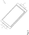
- each cell is structured so that the two electrodes 3 (i.e. a cathode terminal and an anode terminal) protrude from the upper and lower ends of the cell, respectively, and are thus opposite one another.
- the two electrodes 3 i.e. a cathode terminal and an anode terminal
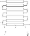
- Figure 1 illustrates a group of cells 2 which are connected to one another in series and overlap one another; for this purpose, the electrodes 3 of two adjacent cells 2 which must be connected to one another are bent at 90° towards one another.
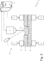
- Figure 3 illustrates a welding unit 5 which executes a weld of an electrode 3 of a cell 2 with another element; in the example illustrated in Figure 3 , the other element is an electrode 3 of another cell 3, but the other element could also be a connecting bar (for example to make a parallel connection between several groups of cells 3) or another electrically conductive component of the battery 1.
- the welding unit 5 comprises a joining device 6 which causes the two electrodes 3 to come into mutual contact (i.e. an electrode 3 and the other element to which the electrode 3 must be welded).
- the joining device 6 comprises two clamps (each consisting of a pair of jaws 7) motorised by means of respective actuators 8.
- the clamps of the joining device 6 press the two electrodes 3 (i.e. an electrode 3 and the other element to which the electrode 3 must be welded) against one another with a predetermined pressure (necessary for executing the weld).
- the welding unit 5 comprises an emitter device 9 which emits a laser beam which is focussed on one of the two electrodes 3 (i.e. on an electrode 3 or on the other element to which the electrode 3 must be welded) and is progressively shifted so as to move along at least one heating line (which can have a linear shape or a curvilinear shape, for example circular); in particular, the laser beam emitted by the emitter device 9 can be progressively shifted so as to move along a single heating line or several heating lines parallel to one another.
- an emitter device 9 which emits a laser beam which is focussed on one of the two electrodes 3 (i.e. on an electrode 3 or on the other element to which the electrode 3 must be welded) and is progressively shifted so as to move along at least one heating line (which can have a linear shape or a curvilinear shape, for example circular); in particular, the laser beam emitted by the emitter device 9 can be progressively shifted so as to move along a single heating line or several heating lines parallel to
- the laser beam emitted by the emitter device 9 provides a concentrated source of heat and thus causes a localized heating of the electrodes 3 (i.e. of an electrode 3 or of the other element to which the electrode 3 must be welded) for locally causing a melting of the metal making up the electrodes 3 so as to generate a weld pool 10 (which is the part of metal that is in the liquid state during the welding).
- the emission of the laser beam is interrupted (i.e. the heating is interrupted) and the weld pool 10 is left to cool down so as to give stability to the weld (i.e. to give the weld a sufficient stability for allowing the piece to be extracted from the welding unit 5 without damaging the weld just executed).
- the welding unit 5 comprises a video camera 11 which is arranged to frame the area in which the weld pool 10 is generated and is thus configured to capture a series of digital images of the weld pool 10 during the heating. Furthermore, the welding unit 5 comprises a processing device 12 which is configured to analyse the digital images so as to determine a value of at least one parameter of the welding process; furthermore, the processing device 12 is configured to change the execution of the melting process (for example the heating) based on the value of the parameter.
- the video camera 11 is a thermal imaging camera (i.e. a thermographic camera) which is sensitive to infrared radiation and, therefore, capable of obtaining thermographic digital images.
- a thermal imaging camera i.e. a thermographic camera
- a first parameter which is determined by the processing device 12 by analysing the thermographic digital images captured by the video camera 11 is a temperature (average, minimum and/or maximum) of the weld pool 10; i.e., the first parameter is dependent on the temperature of the weld pool 10 and can be influenced by the average temperature of the weld pool 10, by the minimum temperature of the weld pool 10, and/or by the maximum temperature of the weld pool 10. If the temperature (average, minimum and/or maximum) of the weld pool 10 is below a first threshold value, the heating (i.e. the quantity of heat transmitted to the weld pool 10) is increased and if the temperature (average, minimum and/or maximum) of the weld pool 10 exceeds a second threshold value, the heating is decreased.
- the first threshold value is (slightly) different from the second threshold value so as to create a "hysteresis" which prevents continuous interventions on the heating power.
- a second parameter which is determined by the processing device 12 by analysing the thermographic digital images captured by the video camera 11 is the size (area) of the weld pool 10. If the size (area) of the weld pool 10 is below a third threshold value, the heating (i.e. the quantity of heat transmitted to the weld pool 10) is increased and if the size of the weld pool 10 exceeds a fourth threshold value, the heating is decreased.
- the third threshold value is (slightly) different from the fourth threshold value so as to create a "hysteresis" which prevents continuous interventions on the heating power.
- the size (not only in terms of area, but also as overall volume) of the weld pool 10 could be determined by the processing device 12 based on a measurement of the electrical resistance between the two electrodes 3 (i.e. between an electrode 3 and the other element to which the electrode 3 must be welded): in fact, the more extended the weld pool 10 (which makes up the "connection bridge" between the two electrodes 3), the lower the electrical resistance between the two electrodes 3.
- the processing device 12 measures, during the execution of the weld (i.e.
- the electrical resistance between the two electrodes 3 and based on the electrical resistance between the two electrodes 3 estimates the size of the weld pool 10 (additionally or alternatively to the measuring of the size of the weld pool 10 by means of the analysis of the digital images).
- the heating is changed (increased or decreased) by changing (increasing or decreasing) a speed with which the laser beam is moved along the heating line; i.e., the slower (the faster) the laser beam moves along the heating line, the greater (the lower) the heating (i.e. the amount of heat transmitted to the weld pool 10).
- the heating could be changed (increased or decreased) by changing (increasing or decreasing) an emission power of the laser beam; i.e., the greater (the lower) the emission power of the laser beam, the greater (the lower) the heating (i.e. the quantity of heat transmitted to the weld pool 10).
- a width is increased (additionally or alternatively to the increase of the heating) of a focussing point of the laser beam (i.e. the focussing point of the laser beam is enlarged) and if the size of the weld pool 10 exceeds the fourth threshold value, the width is decreased (additionally or alternatively to the decrease of the heating) of the focussing point of the laser beam (i.e. the focussing point of the laser beam is narrowed).
- a third parameter which is determined by the processing device 12 by analysing the thermographic digital images captured by the video camera 11 is the (possible) presence of areas of the weld pool 10 without melted metal (i.e. the presence of "holes" in the weld pool 10).
- the processing device 12 acts upon the joining device 6 so as to increase the pressure with which the two electrodes 3 (i.e. an electrode 3 and the other element to which the electrode 3 must be welded) are pressed against one another.
- the heating takes place by means of a laser beam emitted by the emitter device 9.
- the heating takes place by means of ultrasounds, generating vibrations (at ultrasonic frequency) that act upon one of the two electrodes 3 (i.e. on an electrode 3 or upon the other element to which the electrode 3 must be welded);
- the welding unit 5 comprises a sonotrode 13 coupled with a vibrating assembly provided with a piezoelectric transducer.
- the sonotrode 13 generates friction between the two electrodes 3 by means of a vibration with an ultrasonic frequency and this intense vibration generates heat.
- the heating is changed by changing an intensity and/or a frequency of the vibrations.
- the above-described method to execute a weld allows obtaining welds of excellent quality (i.e. of low electrical resistance and of high mechanical resistance) as it allows correcting the welding process during the execution so as to compensate for any accidental errors and thus always ensuring an optimal execution.
- thermographic video camera 11 essentially the thermographic video camera 11
Abstract
Description
- This patent application claims priority from
Italian patent application no. 102020000024940 filed on October 22, 2020 - The present invention relates to a method to execute a weld of an electrode of a cell which is part of a battery.
- Currently, batteries made up of a large number of parallelepiped-shaped pouch cells, each of which has two electrodes (anode and cathode), are very much widespread in the automotive field; in particular, several groups are formed, each having a plurality of cells connected to one another in series while the various groups can be connected to one another in series or parallel.
- The connections of the electrodes of the cells (both with other electrodes and with connecting bars) are normally carried out by means of a welding process that can use the laser welding technology or the ultrasonic welding technology. It is very important that the welding of the electrodes of the cells ensures both a good electrical connection (i.e. an electrical connection with low electrical resistance) so as to prevent excessive power losses due to the Joule effect, and a high mechanical resistance so as to prevent the weld from being broken due to the stresses to which a car battery is subjected during its life (in fact when an impact or a vibration is applied to the battery causing the relative movement of the cells of the battery, the stress can be focussed on the welds of the electrodes).
- Patent application
US2011108181A1 describes a method for the monitoring and the control in real-time of the quality of a vibration welding. - Patent application
KR20200107280A - Patent application
US2017341144A1 describes a method for executing a laser welding of an electrode of a cell which is part of a battery. - Patent application
US2019022793A1 describes a method for determining the quality of a laser welding and in particular for determining the presence of any hot cracks. - Patent application
US2014175071A1 describes a method for determining defects during a laser welding. - The object of the present invention is to provide a method to execute a weld of an electrode of a cell which is part of a battery, which method allows obtaining welds of excellent quality (i.e. of low electrical resistance and of high mechanical resistance) and, simultaneously, is easy and cost-effective to implement.
- According to the present invention, a method to execute a weld of an electrode of a cell which is part of a battery is provided, according to what is claimed in the appended claims.
- The claims describe preferred embodiments of the present invention forming integral part of the present description.
- The present invention will now be described with reference to the accompanying drawings, which illustrate some non-limiting example embodiments thereof, wherein:
-
Figure 1 is a schematic view of a battery made up of a plurality of cells side by side whose electrodes are connected together by means of welding; -
Figure 2 is a perspective and schematic view of a single cell of the battery ofFigure 1 ; -
Figure 3 is a schematic view of a welding unit which executes the weld between two electrodes of respective cells which make up the battery ofFigure 1 ; and -
Figure 4 is a variant of the welding unit ofFigure 3 . - In
Figure 1 , reference numeral 1 indicates, as a whole, a battery for motor vehicles (i.e. for a vehicle with a partially or exclusively electric drive). - The battery 1 comprises a large number of parallelepiped-
shaped pouch cells 2, each of which has two electrodes 3 (anode and cathode); in particular, several groups are formed, each having a plurality ofcells 3 connected to one another in series while the various groups can be connected to one another in series or parallel. - The connections of the
electrodes 3 of the cells 2 (both between thecells 2 and with connecting bars or the like) are obtained by means ofcorresponding welds 4 which are made by means of a welding process which can use the laser welding technology or the ultrasonic welding technology. - As illustrated in
Figure 2 , each cell is structured so that the two electrodes 3 (i.e. a cathode terminal and an anode terminal) protrude from the upper and lower ends of the cell, respectively, and are thus opposite one another. -
Figure 1 illustrates a group ofcells 2 which are connected to one another in series and overlap one another; for this purpose, theelectrodes 3 of twoadjacent cells 2 which must be connected to one another are bent at 90° towards one another. -
Figure 3 illustrates awelding unit 5 which executes a weld of anelectrode 3 of acell 2 with another element; in the example illustrated inFigure 3 , the other element is anelectrode 3 of anothercell 3, but the other element could also be a connecting bar (for example to make a parallel connection between several groups of cells 3) or another electrically conductive component of the battery 1. - The
welding unit 5 comprises a joiningdevice 6 which causes the twoelectrodes 3 to come into mutual contact (i.e. anelectrode 3 and the other element to which theelectrode 3 must be welded). In particular, the joiningdevice 6 comprises two clamps (each consisting of a pair of jaws 7) motorised by means ofrespective actuators 8. - The clamps of the joining
device 6 press the two electrodes 3 (i.e. anelectrode 3 and the other element to which theelectrode 3 must be welded) against one another with a predetermined pressure (necessary for executing the weld). - The
welding unit 5 comprises anemitter device 9 which emits a laser beam which is focussed on one of the two electrodes 3 (i.e. on anelectrode 3 or on the other element to which theelectrode 3 must be welded) and is progressively shifted so as to move along at least one heating line (which can have a linear shape or a curvilinear shape, for example circular); in particular, the laser beam emitted by theemitter device 9 can be progressively shifted so as to move along a single heating line or several heating lines parallel to one another. - The laser beam emitted by the
emitter device 9 provides a concentrated source of heat and thus causes a localized heating of the electrodes 3 (i.e. of anelectrode 3 or of the other element to which theelectrode 3 must be welded) for locally causing a melting of the metal making up theelectrodes 3 so as to generate a weld pool 10 (which is the part of metal that is in the liquid state during the welding). - Once the
weld pool 10 has reached the optimal (desired) size, the emission of the laser beam is interrupted (i.e. the heating is interrupted) and theweld pool 10 is left to cool down so as to give stability to the weld (i.e. to give the weld a sufficient stability for allowing the piece to be extracted from thewelding unit 5 without damaging the weld just executed). - The
welding unit 5 comprises avideo camera 11 which is arranged to frame the area in which theweld pool 10 is generated and is thus configured to capture a series of digital images of theweld pool 10 during the heating. Furthermore, thewelding unit 5 comprises aprocessing device 12 which is configured to analyse the digital images so as to determine a value of at least one parameter of the welding process; furthermore, theprocessing device 12 is configured to change the execution of the melting process (for example the heating) based on the value of the parameter. - Preferably, the
video camera 11 is a thermal imaging camera (i.e. a thermographic camera) which is sensitive to infrared radiation and, therefore, capable of obtaining thermographic digital images. - A first parameter which is determined by the
processing device 12 by analysing the thermographic digital images captured by thevideo camera 11 is a temperature (average, minimum and/or maximum) of theweld pool 10; i.e., the first parameter is dependent on the temperature of theweld pool 10 and can be influenced by the average temperature of theweld pool 10, by the minimum temperature of theweld pool 10, and/or by the maximum temperature of theweld pool 10. If the temperature (average, minimum and/or maximum) of theweld pool 10 is below a first threshold value, the heating (i.e. the quantity of heat transmitted to the weld pool 10) is increased and if the temperature (average, minimum and/or maximum) of theweld pool 10 exceeds a second threshold value, the heating is decreased. Generally, the first threshold value is (slightly) different from the second threshold value so as to create a "hysteresis" which prevents continuous interventions on the heating power. - A second parameter which is determined by the
processing device 12 by analysing the thermographic digital images captured by thevideo camera 11 is the size (area) of theweld pool 10. If the size (area) of theweld pool 10 is below a third threshold value, the heating (i.e. the quantity of heat transmitted to the weld pool 10) is increased and if the size of theweld pool 10 exceeds a fourth threshold value, the heating is decreased. - Generally, the third threshold value is (slightly) different from the fourth threshold value so as to create a "hysteresis" which prevents continuous interventions on the heating power.
- Alternatively or additionally to the analysis of the digital images, the size (not only in terms of area, but also as overall volume) of the
weld pool 10 could be determined by theprocessing device 12 based on a measurement of the electrical resistance between the two electrodes 3 (i.e. between anelectrode 3 and the other element to which theelectrode 3 must be welded): in fact, the more extended the weld pool 10 (which makes up the "connection bridge" between the two electrodes 3), the lower the electrical resistance between the twoelectrodes 3. In other words, theprocessing device 12 measures, during the execution of the weld (i.e. when theweld pool 10 has been created), the electrical resistance between the twoelectrodes 3 and based on the electrical resistance between the twoelectrodes 3 estimates the size of the weld pool 10 (additionally or alternatively to the measuring of the size of theweld pool 10 by means of the analysis of the digital images). - Preferably, the heating is changed (increased or decreased) by changing (increasing or decreasing) a speed with which the laser beam is moved along the heating line; i.e., the slower (the faster) the laser beam moves along the heating line, the greater (the lower) the heating (i.e. the amount of heat transmitted to the weld pool 10). Alternatively or additionally, the heating could be changed (increased or decreased) by changing (increasing or decreasing) an emission power of the laser beam; i.e., the greater (the lower) the emission power of the laser beam, the greater (the lower) the heating (i.e. the quantity of heat transmitted to the weld pool 10).
- According to a possible embodiment, if the size of the
weld pool 10 is below the third threshold value, a width is increased (additionally or alternatively to the increase of the heating) of a focussing point of the laser beam (i.e. the focussing point of the laser beam is enlarged) and if the size of theweld pool 10 exceeds the fourth threshold value, the width is decreased (additionally or alternatively to the decrease of the heating) of the focussing point of the laser beam (i.e. the focussing point of the laser beam is narrowed). - A third parameter which is determined by the
processing device 12 by analysing the thermographic digital images captured by thevideo camera 11 is the (possible) presence of areas of theweld pool 10 without melted metal (i.e. the presence of "holes" in the weld pool 10). In case of presence of areas of theweld pool 10 without melted metal (i.e. in case of "holes" in the weld pool 10), theprocessing device 12 acts upon the joiningdevice 6 so as to increase the pressure with which the two electrodes 3 (i.e. anelectrode 3 and the other element to which theelectrode 3 must be welded) are pressed against one another. - In the embodiment illustrated in
Figure 3 , the heating takes place by means of a laser beam emitted by theemitter device 9. In the variant illustrated inFigure 4 , the heating takes place by means of ultrasounds, generating vibrations (at ultrasonic frequency) that act upon one of the two electrodes 3 (i.e. on anelectrode 3 or upon the other element to which theelectrode 3 must be welded); in particular, thewelding unit 5 comprises asonotrode 13 coupled with a vibrating assembly provided with a piezoelectric transducer. Thesonotrode 13 generates friction between the twoelectrodes 3 by means of a vibration with an ultrasonic frequency and this intense vibration generates heat. In this embodiment, the heating is changed by changing an intensity and/or a frequency of the vibrations. - The above-described method to execute a weld has numerous advantages.
- In the first place, the above-described method to execute a weld allows obtaining welds of excellent quality (i.e. of low electrical resistance and of high mechanical resistance) as it allows correcting the welding process during the execution so as to compensate for any accidental errors and thus always ensuring an optimal execution.
- Furthermore, the above-described method to execute a weld is easy and cost-effective to implement as it requires the use of commercial components (essentially the thermographic video camera 11) of relatively modest cost and as it requires a modest computing power for the modern processing systems.
-
- 1
- battery
- 2
- cells
- 3
- electrodes
- 4
- welds
- 5
- welding unit
- 6
- joining device
- 7
- jaws
- 8
- actuators
- 9
- emitter device
- 10
- weld pool
- 11
- video camera
- 12
- processing device
- 13
- sonotrode
Claims (16)
- A method to execute a weld of an electrode (3) of a cell (2) which is part of a battery (1); the execution method comprises the steps of:causing the electrode (3) to come into contact with another element to which the electrode (3) must be welded;locally heating the electrode (3) and the other element so as to locally cause a melting of the metal making up the electrode (3) and of the metal making up the other element in order to generate a weld pool (10);waiting for the weld pool (10) to cool down, thus giving stability to the weld;capturing, by means of a video camera (11), a series of digital images of the weld pool (10) during the heating;analysing the digital images in order to determine a value of at least one first parameter of the welding process; andchanging the execution of the melting process based on the value of the first parameter;the execution method is characterized in that:
the first parameter is the presence of areas of the weld pool (10) without melted metal. - The weld execution method according to claim 1, wherein:the electrode (3) and the other element are pressed against one another with a predetermined pressure; andin case of presence of areas of the weld pool (10) without melted metal, the pressure with which the electrode (3) and the other element are pressed against one another is increased.
- The weld execution method according to claim 1 or 2, wherein the video camera (11) is a thermographic camera which is sensitive to infrared radiation and, therefore, is capable of generating thermographic digital images.
- The weld execution method according to claim 2, wherein a second parameter additional to the first parameter is a temperature of the weld pool (10).
- The weld execution method according to claim 4, wherein the heating is changed based on the temperature of the weld pool (10).
- The weld execution method according to claim 4 or 5, wherein, if the temperature of the weld pool (10) is below a first threshold value, the heating is increased and, if the temperature of the weld pool (10) exceeds a second threshold value, the heating is decreased.
- The weld execution method according to one of the claims from 3 to 6, wherein a second parameter additional to the first parameter is a size of the weld pool (10).
- The weld execution method according to claim 6, wherein the heating is changed based on the size of the weld pool (10).
- The weld execution method according to claim 7 or 8, wherein, if the size of the weld pool (10) is below a third threshold value, the heating is increased and, if the size of the weld pool (10) exceeds a fourth threshold value, the heating is decreased.
- The weld execution method according to claim 7, 8 or 9, wherein:the heating takes place by means of a laser beam, which is focussed on the electrode (3) or on the other element and is progressively shifted so as to move along at least one heating line; andif the size of the weld pool (10) is below a third threshold value, a width of a focussing point of the laser beam is increased and, if the size of the weld pool (10) exceeds a fourth threshold value, the width of the focussing point of the laser beam is decreased.
- The weld execution method according to any one of the claims from 7 to 10, wherein the size of the weld pool (10) is also determined based on a measure of the electrical resistance between the electrode (3) and the other element.
- The weld execution method according to claim 6 or 9, wherein:the heating takes place by means of a laser beam, which is focussed on the electrode (3) or on the other element and is progressively shifted so as to move along at least one heating line; andthe heating is changed by changing a speed with which the laser beam is moved along the heating line.
- The weld execution method according to claim 6 or 9, wherein:the heating takes place by means of ultrasounds generating vibrations that act upon the electrode (3) or upon the other element; andthe heating is changed by changing an intensity and/or a frequency of the vibrations.
- A method to execute a weld of an electrode (3) of a cell (2) which is part of a battery (1); the execution method comprises the steps of:causing the electrode (3) to come into contact with another element to which the electrode (3) must be welded;locally heating the electrode (3) and the other element so as to locally cause a melting of the metal making up the electrode (3) and of the metal making up the other element in order to generate a weld pool (10);waiting for the weld pool (10) to cool down, thus giving stability to the weld;determining a size of the weld pool (10) during the heating; andchanging the execution of the melting process based on the size of the weld pool (10);the execution method is characterized in that it comprises the further steps of:measuring an electrical resistance between the electrode (3) and the other element during the heating; anddetermining the size of the weld pool (10) based on the electrical resistance between the electrode (3) and the other element.
- The weld execution method according to claim 14, wherein the size of the weld pool (10) is estimated the larger the smaller the electrical resistance between the electrode (3) and the other element.
- The weld execution method according to claim 14 or 15 and comprising the further steps of:capturing, by means of a video camera (11) sensitive to infrared radiation, a series of thermographic digital images of the weld pool (10) during the heating; andanalysing the thermographic digital images to determine the size of the weld pool (10) in addition to the determination of the size of the weld pool (10) carried out based on the electrical resistance between the electrode (3) and the other element.
Applications Claiming Priority (1)
| Application Number | Priority Date | Filing Date | Title |
|---|---|---|---|
| IT202000024940 | 2020-10-22 |
Publications (2)
| Publication Number | Publication Date |
|---|---|
| EP3988236A1 true EP3988236A1 (en) | 2022-04-27 |
| EP3988236B1 EP3988236B1 (en) | 2024-02-28 |
Family
ID=74068602
Family Applications (1)
| Application Number | Title | Priority Date | Filing Date |
|---|---|---|---|
| EP21204191.7A Active EP3988236B1 (en) | 2020-10-22 | 2021-10-22 | Method to execute a weld of an electrode of a cell which is part of a battery |
Country Status (2)
| Country | Link |
|---|---|
| US (1) | US20220126400A1 (en) |
| EP (1) | EP3988236B1 (en) |
Families Citing this family (1)
| Publication number | Priority date | Publication date | Assignee | Title |
|---|---|---|---|---|
| CN117283133B (en) * | 2023-11-22 | 2024-02-20 | 海菲曼(天津)科技有限公司 | Earphone production line electrode laser welding method and laser welding equipment |
Citations (7)
| Publication number | Priority date | Publication date | Assignee | Title |
|---|---|---|---|---|
| US20100314362A1 (en) * | 2009-06-11 | 2010-12-16 | Illinois Tool Works Inc. | Weld defect detection systems and methods for laser hybrid welding |
| US20110108181A1 (en) | 2009-11-09 | 2011-05-12 | Gm Global Technology Operations, Inc. | Method and system for online quality monitoring and control of a vibration welding process |
| DE102011078276B3 (en) * | 2011-06-29 | 2012-12-06 | Trumpf Laser- Und Systemtechnik Gmbh | Method for detecting errors during a laser machining process and laser machining apparatus |
| DE102016204577A1 (en) * | 2016-03-18 | 2017-09-21 | Trumpf Laser- Und Systemtechnik Gmbh | Hot crack detection during laser welding |
| US20170341144A1 (en) | 2016-04-29 | 2017-11-30 | Nuburu, Inc. | Visible Laser Welding of Electronic Packaging, Automotive Electrics, Battery and Other Components |
| US20200230732A1 (en) * | 2015-12-07 | 2020-07-23 | Illinois Tool Works Inc. | Systems and methods for automated root pass welding |
| KR20200107280A (en) | 2019-03-07 | 2020-09-16 | 주식회사 엘지화학 | Method for Optimizing Ultrasonic Welding Process of Lithium Secondary Battery and Apparatus Thereof |
-
2021
- 2021-10-20 US US17/505,787 patent/US20220126400A1/en active Pending
- 2021-10-22 EP EP21204191.7A patent/EP3988236B1/en active Active
Patent Citations (9)
| Publication number | Priority date | Publication date | Assignee | Title |
|---|---|---|---|---|
| US20100314362A1 (en) * | 2009-06-11 | 2010-12-16 | Illinois Tool Works Inc. | Weld defect detection systems and methods for laser hybrid welding |
| US20110108181A1 (en) | 2009-11-09 | 2011-05-12 | Gm Global Technology Operations, Inc. | Method and system for online quality monitoring and control of a vibration welding process |
| DE102011078276B3 (en) * | 2011-06-29 | 2012-12-06 | Trumpf Laser- Und Systemtechnik Gmbh | Method for detecting errors during a laser machining process and laser machining apparatus |
| US20140175071A1 (en) | 2011-06-29 | 2014-06-26 | Trumpf Laser - Und Systemtechnik Gmbh | Method for Detecting Defects During a Laser-Machining Process and Laser-Machining Device |
| US20200230732A1 (en) * | 2015-12-07 | 2020-07-23 | Illinois Tool Works Inc. | Systems and methods for automated root pass welding |
| DE102016204577A1 (en) * | 2016-03-18 | 2017-09-21 | Trumpf Laser- Und Systemtechnik Gmbh | Hot crack detection during laser welding |
| US20190022793A1 (en) | 2016-03-18 | 2019-01-24 | Trumpf Laser- Und Systemtechnik Gmbh | Detection of hot cracks in laser welding |
| US20170341144A1 (en) | 2016-04-29 | 2017-11-30 | Nuburu, Inc. | Visible Laser Welding of Electronic Packaging, Automotive Electrics, Battery and Other Components |
| KR20200107280A (en) | 2019-03-07 | 2020-09-16 | 주식회사 엘지화학 | Method for Optimizing Ultrasonic Welding Process of Lithium Secondary Battery and Apparatus Thereof |
Also Published As
| Publication number | Publication date |
|---|---|
| US20220126400A1 (en) | 2022-04-28 |
| EP3988236B1 (en) | 2024-02-28 |
Similar Documents
| Publication | Publication Date | Title |
|---|---|---|
| KR102202512B1 (en) | Method of welding laminated metal foils | |
| US6518536B2 (en) | Joining equipment | |
| EP3988236B1 (en) | Method to execute a weld of an electrode of a cell which is part of a battery | |
| KR101235584B1 (en) | Ultrasonic welding system and method for forming a weld joint | |
| KR102047926B1 (en) | Blue Laser Combined Laser Welding Monitoring System | |
| JP2009119957A (en) | Electronic control device and its manufacturing method | |
| CN103702792A (en) | Joining sheet metal-type components having an intermediate layer made of thermoplastic synthetic material | |
| US11203085B2 (en) | Method and apparatus for laser welding | |
| KR101894026B1 (en) | Device and method for the friction-stir welding of an assembly for storing electricity | |
| JP4735184B2 (en) | Abnormality discrimination evaluation method for welded workpiece and abnormality discrimination evaluation device | |
| KR101240453B1 (en) | Apparatus and Method for Welding of Electrode of Secondary Battery | |
| CN106271071A (en) | A kind of laser welding work station | |
| KR102240307B1 (en) | Method of welding laminated metal foils | |
| KR20220145055A (en) | Welding Inspection Device Comprising Thermal Imaging Camera | |
| JP2015074028A (en) | Pressure laser welding method and device | |
| KR101452585B1 (en) | Ultasonic fusion checking method for electrode cell | |
| JP4224050B2 (en) | Heater chip thermocouple mounting structure and thermocouple mounting method | |
| US20210205926A1 (en) | Method for connecting two components and component composite | |
| KR101923667B1 (en) | Electric resistance spot welding machine with double composite electrode tips | |
| WO2024009875A1 (en) | Forge welding apparatus | |
| TWI616263B (en) | Method for detecting an abnormal event for laser-welding process and detecting system using the same | |
| JPH0644029Y2 (en) | Battery with lead terminal | |
| JP2023146170A (en) | Spot weld zone inspection method | |
| Dave | Bimetallic materials welding and analysis for battery packs of electric vehicles | |
| JP2021171788A (en) | Resistance-welding control system and resistance-welding control method |
Legal Events
| Date | Code | Title | Description |
|---|---|---|---|
| PUAI | Public reference made under article 153(3) epc to a published international application that has entered the european phase |
Free format text: ORIGINAL CODE: 0009012 |
|
| STAA | Information on the status of an ep patent application or granted ep patent |
Free format text: STATUS: THE APPLICATION HAS BEEN PUBLISHED |
|
| STAA | Information on the status of an ep patent application or granted ep patent |
Free format text: STATUS: REQUEST FOR EXAMINATION WAS MADE |
|
| AK | Designated contracting states |
Kind code of ref document: A1 Designated state(s): AL AT BE BG CH CY CZ DE DK EE ES FI FR GB GR HR HU IE IS IT LI LT LU LV MC MK MT NL NO PL PT RO RS SE SI SK SM TR |
|
| 17P | Request for examination filed |
Effective date: 20220411 |
|
| P01 | Opt-out of the competence of the unified patent court (upc) registered |
Effective date: 20230525 |
|
| GRAP | Despatch of communication of intention to grant a patent |
Free format text: ORIGINAL CODE: EPIDOSNIGR1 |
|
| STAA | Information on the status of an ep patent application or granted ep patent |
Free format text: STATUS: GRANT OF PATENT IS INTENDED |
|
| INTG | Intention to grant announced |
Effective date: 20230928 |
|
| RIC1 | Information provided on ipc code assigned before grant |
Ipc: B23K 101/36 20060101ALN20230915BHEP Ipc: B23K 101/38 20060101ALN20230915BHEP Ipc: B23K 26/244 20140101ALI20230915BHEP Ipc: B23K 31/12 20060101ALI20230915BHEP Ipc: B23K 26/26 20140101ALI20230915BHEP Ipc: B23K 26/03 20060101ALI20230915BHEP Ipc: B23K 20/10 20060101AFI20230915BHEP |
|
| GRAS | Grant fee paid |
Free format text: ORIGINAL CODE: EPIDOSNIGR3 |
|
| GRAA | (expected) grant |
Free format text: ORIGINAL CODE: 0009210 |
|
| STAA | Information on the status of an ep patent application or granted ep patent |
Free format text: STATUS: THE PATENT HAS BEEN GRANTED |
|
| AK | Designated contracting states |
Kind code of ref document: B1 Designated state(s): AL AT BE BG CH CY CZ DE DK EE ES FI FR GB GR HR HU IE IS IT LI LT LU LV MC MK MT NL NO PL PT RO RS SE SI SK SM TR |
|
| REG | Reference to a national code |
Ref country code: GB Ref legal event code: FG4D |
|
| REG | Reference to a national code |
Ref country code: CH Ref legal event code: EP |
|
| REG | Reference to a national code |
Ref country code: DE Ref legal event code: R096 Ref document number: 602021009798 Country of ref document: DE |
|
| REG | Reference to a national code |
Ref country code: IE Ref legal event code: FG4D |