EP3988222B1 - Projectile launching apparatus configured to clean an inner surface of a tube - Google Patents
Projectile launching apparatus configured to clean an inner surface of a tube Download PDFInfo
- Publication number
- EP3988222B1 EP3988222B1 EP21203693.3A EP21203693A EP3988222B1 EP 3988222 B1 EP3988222 B1 EP 3988222B1 EP 21203693 A EP21203693 A EP 21203693A EP 3988222 B1 EP3988222 B1 EP 3988222B1
- Authority
- EP
- European Patent Office
- Prior art keywords
- tube
- projectile
- hose
- accordance
- port
- Prior art date
- Legal status (The legal status is an assumption and is not a legal conclusion. Google has not performed a legal analysis and makes no representation as to the accuracy of the status listed.)
- Active
Links
Images




Classifications
-
- B—PERFORMING OPERATIONS; TRANSPORTING
- B08—CLEANING
- B08B—CLEANING IN GENERAL; PREVENTION OF FOULING IN GENERAL
- B08B9/00—Cleaning hollow articles by methods or apparatus specially adapted thereto
- B08B9/02—Cleaning pipes or tubes or systems of pipes or tubes
- B08B9/027—Cleaning the internal surfaces; Removal of blockages
- B08B9/04—Cleaning the internal surfaces; Removal of blockages using cleaning devices introduced into and moved along the pipes
- B08B9/053—Cleaning the internal surfaces; Removal of blockages using cleaning devices introduced into and moved along the pipes moved along the pipes by a fluid, e.g. by fluid pressure or by suction
- B08B9/055—Cleaning the internal surfaces; Removal of blockages using cleaning devices introduced into and moved along the pipes moved along the pipes by a fluid, e.g. by fluid pressure or by suction the cleaning devices conforming to, or being conformable to, substantially the same cross-section of the pipes, e.g. pigs or moles
- B08B9/0558—Cleaning the internal surfaces; Removal of blockages using cleaning devices introduced into and moved along the pipes moved along the pipes by a fluid, e.g. by fluid pressure or by suction the cleaning devices conforming to, or being conformable to, substantially the same cross-section of the pipes, e.g. pigs or moles with additional jet means
-
- B—PERFORMING OPERATIONS; TRANSPORTING
- B08—CLEANING
- B08B—CLEANING IN GENERAL; PREVENTION OF FOULING IN GENERAL
- B08B13/00—Accessories or details of general applicability for machines or apparatus for cleaning
-
- B—PERFORMING OPERATIONS; TRANSPORTING
- B08—CLEANING
- B08B—CLEANING IN GENERAL; PREVENTION OF FOULING IN GENERAL
- B08B9/00—Cleaning hollow articles by methods or apparatus specially adapted thereto
- B08B9/02—Cleaning pipes or tubes or systems of pipes or tubes
- B08B9/027—Cleaning the internal surfaces; Removal of blockages
- B08B9/04—Cleaning the internal surfaces; Removal of blockages using cleaning devices introduced into and moved along the pipes
- B08B9/053—Cleaning the internal surfaces; Removal of blockages using cleaning devices introduced into and moved along the pipes moved along the pipes by a fluid, e.g. by fluid pressure or by suction
- B08B9/055—Cleaning the internal surfaces; Removal of blockages using cleaning devices introduced into and moved along the pipes moved along the pipes by a fluid, e.g. by fluid pressure or by suction the cleaning devices conforming to, or being conformable to, substantially the same cross-section of the pipes, e.g. pigs or moles
- B08B9/0551—Control mechanisms therefor
-
- B—PERFORMING OPERATIONS; TRANSPORTING
- B08—CLEANING
- B08B—CLEANING IN GENERAL; PREVENTION OF FOULING IN GENERAL
- B08B9/00—Cleaning hollow articles by methods or apparatus specially adapted thereto
- B08B9/02—Cleaning pipes or tubes or systems of pipes or tubes
- B08B9/027—Cleaning the internal surfaces; Removal of blockages
- B08B9/04—Cleaning the internal surfaces; Removal of blockages using cleaning devices introduced into and moved along the pipes
- B08B9/053—Cleaning the internal surfaces; Removal of blockages using cleaning devices introduced into and moved along the pipes moved along the pipes by a fluid, e.g. by fluid pressure or by suction
- B08B9/055—Cleaning the internal surfaces; Removal of blockages using cleaning devices introduced into and moved along the pipes moved along the pipes by a fluid, e.g. by fluid pressure or by suction the cleaning devices conforming to, or being conformable to, substantially the same cross-section of the pipes, e.g. pigs or moles
- B08B9/0553—Cylindrically shaped pigs
-
- F—MECHANICAL ENGINEERING; LIGHTING; HEATING; WEAPONS; BLASTING
- F41—WEAPONS
- F41B—WEAPONS FOR PROJECTING MISSILES WITHOUT USE OF EXPLOSIVE OR COMBUSTIBLE PROPELLANT CHARGE; WEAPONS NOT OTHERWISE PROVIDED FOR
- F41B11/00—Compressed-gas guns, e.g. air guns; Steam guns
- F41B11/80—Compressed-gas guns, e.g. air guns; Steam guns specially adapted for particular purposes
- F41B11/87—Compressed-gas guns, e.g. air guns; Steam guns specially adapted for particular purposes for industrial purposes, e.g. for surface treatment
-
- B—PERFORMING OPERATIONS; TRANSPORTING
- B08—CLEANING
- B08B—CLEANING IN GENERAL; PREVENTION OF FOULING IN GENERAL
- B08B2209/00—Details of machines or methods for cleaning hollow articles
- B08B2209/02—Details of apparatuses or methods for cleaning pipes or tubes
- B08B2209/027—Details of apparatuses or methods for cleaning pipes or tubes for cleaning the internal surfaces
- B08B2209/04—Details of apparatuses or methods for cleaning pipes or tubes for cleaning the internal surfaces using cleaning devices introduced into and moved along the pipes
- B08B2209/053—Details of apparatuses or methods for cleaning pipes or tubes for cleaning the internal surfaces using cleaning devices introduced into and moved along the pipes being moved along the pipes by a fluid, e.g. by fluid pressure or by suction
- B08B2209/055—Details of apparatuses or methods for cleaning pipes or tubes for cleaning the internal surfaces using cleaning devices introduced into and moved along the pipes being moved along the pipes by a fluid, e.g. by fluid pressure or by suction the cleaning devices conforming to, or being conformable to, substantially the same cross-section of the pipes, e.g. pigs or moles
Definitions
- the present disclosure relates to apparatuses and methods for firing a projectile; more particularly, to such apparatuses and methods for injecting a cleaning projectile into a tube for cleaning the internal walls of the tube; and most particularly, to apparatuses and methods for cleaning conduits by propelling a foam projectile through the conduit by means of a compressed gas charge.
- This disclosure also relates to projectile launchers and methods of manufacture and use thereof.
- the present disclosure relates to tube cleaning and particularly to propelling foam pellets by compressed gas through hydraulic hose, tubes, piping, conduits, and the like for cleaning interior surfaces thereof.
- the compressed gas used here is preferably chosen from any regularly available gases and mixtures thereof, including but not limited to air, nitrogen, carbon dioxide, argon, and/or helium, or other suitable gases.
- Compressed gas-propelled foam pellets or projectiles are used for cleaning the interior surface of a variety of conduits including hydraulic and pneumatic lines wherein the foam projectile removes particulate matter, wipes the interior wall, and absorbs surface film.
- the projectile is compressible, and its outer diameter is greater than the conduit bore diameter. The projectile acts as a seal against the interior wall such that the full force of the compressed gas is able to move the projectile through a conduit.
- Foam projectiles are available in a range of diameters for use in cleaning conduits in a corresponding range of diameters. Foam projectiles are especially useful in certain applications where the tubing to be cleaned has a plurality of sharp bends as in an air handling system or air conditioner.
- Handheld pneumatic guns of the type described in U.S. Pat. No. 4,974,277 are used to position a projectile for entry into a conduit, and to propel the projectile through the conduit with compressed gas.
- a pneumatic gun of this type includes interchangeable nozzles in different sizes to accommodate different size projectiles for application over a range of conduit diameters.
- the pneumatic gun includes a pivoting breech ring for interchanging nozzles and for hand loading projectiles one-by-one into the nozzle.
- the breech ring pivots open for breech loading of a projectile into the gun nozzle.
- the breech ring is then closed manually.
- an operator can fire a compressed gas charge that propels the projectile through the conduit.
- the compressed gas charge is completely dissipated. This loading and firing sequence are repeated for each projectile loaded into the pneumatic gun.
- US Patent No. 6,631,531 B1 discloses a pneumatic air gun for conduit cleaning with foam projectiles, comprising a hand grip with actuating trigger, projectile loading chamber with a quick load port, a nozzle, and a compressed gas circuit including an air flow control valve for directing air in propelling a projectile and for dissipating an air charge in the event of a conduit obstruction.
- a projectile loading chamber surmounts the gun's handgrip and includes a quick load port through which projectiles are loaded axially into a nozzle fitted to the front of the projectile chamber, also known as the "breech", and terminating in a tapered nipple.
- a door or port closure member in the breech chamber is spring- biased to a normally closed position over the port.
- foam projectiles are pushed through the port closure into a nozzle, with the closure then returning to closed position.
- the breech chamber as well as the nozzle interior behind the projectile then receive a compressed gas charge when the trigger is pulled. Compressed gas propels the projectile through a conduit, cleaning its interior wall.
- the nozzle is mounted in a pivoting breech ring that terminates the projectile chamber so that the chamber may be broken open" in a manner similar to a double-barrel shotgun for interchange of a range of nozzle and projectile sizes for cleaning conduits in a corresponding range of diameters.
- compressed gas flows from a source through the gun's handgrip and through a trigger-actuated air flow control valve into the breech.
- the air pressure is dissipated backwards through the air flow control valve when the operator releases the trigger.
- the built-up compressed gas is diverted harmlessly through an exhaust circuit opened as the trigger is released. Trigger release also stops further flow of compressed gas into the gun chamber.
- a shortcoming of the '531 patent is that in operation the apparatus is coupled to the tube to be cleaned solely by forcing the nozzle nipple into the end of the tube and holding it there by operator pressure. air pressure is maintained until the trigger is released; thus, if the tube is fully blocked, the apparatus may become instantaneously and uncontrollably decoupled from the tube.
- This arrangement can be effective in shortening the cycle time for cleaning a plurality of tubes, but it requires close attention in operation.
- the axial breech loading mechanism including the port closure mechanism, requires a relatively large projectile loading chamber and a concomitantly large gun housing.
Landscapes
- Engineering & Computer Science (AREA)
- Physics & Mathematics (AREA)
- Fluid Mechanics (AREA)
- Mechanical Engineering (AREA)
- General Engineering & Computer Science (AREA)
- Toys (AREA)
- Aiming, Guidance, Guns With A Light Source, Armor, Camouflage, And Targets (AREA)
- Cleaning In General (AREA)
Description
- The present disclosure relates to apparatuses and methods for firing a projectile; more particularly, to such apparatuses and methods for injecting a cleaning projectile into a tube for cleaning the internal walls of the tube; and most particularly, to apparatuses and methods for cleaning conduits by propelling a foam projectile through the conduit by means of a compressed gas charge. This disclosure also relates to projectile launchers and methods of manufacture and use thereof.
- The present disclosure relates to tube cleaning and particularly to propelling foam pellets by compressed gas through hydraulic hose, tubes, piping, conduits, and the like for cleaning interior surfaces thereof. The compressed gas used here is preferably chosen from any regularly available gases and mixtures thereof, including but not limited to air, nitrogen, carbon dioxide, argon, and/or helium, or other suitable gases. Compressed gas-propelled foam pellets or projectiles are used for cleaning the interior surface of a variety of conduits including hydraulic and pneumatic lines wherein the foam projectile removes particulate matter, wipes the interior wall, and absorbs surface film. Preferably, for effective cleaning of the interior wall, the projectile is compressible, and its outer diameter is greater than the conduit bore diameter. The projectile acts as a seal against the interior wall such that the full force of the compressed gas is able to move the projectile through a conduit.
- Foam projectiles are available in a range of diameters for use in cleaning conduits in a corresponding range of diameters. Foam projectiles are especially useful in certain applications where the tubing to be cleaned has a plurality of sharp bends as in an air handling system or air conditioner.
- Handheld pneumatic guns of the type described in
U.S. Pat. No. 4,974,277 are used to position a projectile for entry into a conduit, and to propel the projectile through the conduit with compressed gas. A pneumatic gun of this type includes interchangeable nozzles in different sizes to accommodate different size projectiles for application over a range of conduit diameters. - The pneumatic gun includes a pivoting breech ring for interchanging nozzles and for hand loading projectiles one-by-one into the nozzle. In a first position, the breech ring pivots open for breech loading of a projectile into the gun nozzle. The breech ring is then closed manually. By positioning the gun muzzle adjacent a conduit opening and pulling the trigger, an operator can fire a compressed gas charge that propels the projectile through the conduit. When the projectile passes through the conduit, the compressed gas charge is completely dissipated. This loading and firing sequence are repeated for each projectile loaded into the pneumatic gun.
- The steps of opening and closing a pneumatic gun breech for each projectile adds to the complexity and time consumed for completing a conduit cleaning work schedule.
- In the event a conduit is obstructed or blocked and the projectile travels into but not through a conduit, the compressed gas charge is not dissipated and acts to force the air gun violently away from the conduit opening. Thus, the potential for obstructed conduits presents a safety hazard for an air gun operator and creates a need for fail-safe dissipation of compressed gas charges in these circumstances.
-
US Patent No. 6,631,531 B1 ( hereinafter the '531 patent), discloses a pneumatic air gun for conduit cleaning with foam projectiles, comprising a hand grip with actuating trigger, projectile loading chamber with a quick load port, a nozzle, and a compressed gas circuit including an air flow control valve for directing air in propelling a projectile and for dissipating an air charge in the event of a conduit obstruction. - In one aspect of the pneumatic air gun, a projectile loading chamber surmounts the gun's handgrip and includes a quick load port through which projectiles are loaded axially into a nozzle fitted to the front of the projectile chamber, also known as the "breech", and terminating in a tapered nipple. A door or port closure member in the breech chamber is spring- biased to a normally closed position over the port. For loading the gun, foam projectiles are pushed through the port closure into a nozzle, with the closure then returning to closed position. The breech chamber as well as the nozzle interior behind the projectile then receive a compressed gas charge when the trigger is pulled. Compressed gas propels the projectile through a conduit, cleaning its interior wall. Another projectile may then be loaded and fired in the same way. The nozzle is mounted in a pivoting breech ring that terminates the projectile chamber so that the chamber may be broken open" in a manner similar to a double-barrel shotgun for interchange of a range of nozzle and projectile sizes for cleaning conduits in a corresponding range of diameters.
- In another aspect of the pneumatic air gun, compressed gas flows from a source through the gun's handgrip and through a trigger-actuated air flow control valve into the breech. In the event pressurized air remains in the gun after firing a projectile, by reason of an obstructed conduit, the air pressure is dissipated backwards through the air flow control valve when the operator releases the trigger. The built-up compressed gas is diverted harmlessly through an exhaust circuit opened as the trigger is released. Trigger release also stops further flow of compressed gas into the gun chamber.
- A shortcoming of the '531 patent is that in operation the apparatus is coupled to the tube to be cleaned solely by forcing the nozzle nipple into the end of the tube and holding it there by operator pressure. air pressure is maintained until the trigger is released; thus, if the tube is fully blocked, the apparatus may become instantaneously and uncontrollably decoupled from the tube. This arrangement can be effective in shortening the cycle time for cleaning a plurality of tubes, but it requires close attention in operation. Further, the axial breech loading mechanism, including the port closure mechanism, requires a relatively large projectile loading chamber and a concomitantly large gun housing.
- Published German patent application
DE4223054A1 discloses one or more compressible sponge plugs that are driven through the hose or passage to be cleaned by the application of compressed air. In the uncompressed condition the sponge plug is larger in diameter than the passage. The diameter of the air jet, which is directed axially at the sponge plug, is smaller than the diameter of the passage. The method is applied to a hose e.g. by the use of an adaptor with compressed air inlet and a downstream compressed air outlet connecting to the hose to be cleaned. In the side of the adaptor is an opening for the insertion of the sponge plug. The opening is sealed off with a cover. - Published US patent application
US2006/179588 discloses an apparatus for the rapid loading, launching and retrieval of foam pellets for tube cleaning. The apparatus uses a block configuration to allow gravity feed and rapid firing of pellets into tubes. The apparatus includes a hopper feeder attachment, which is self-adjusting during pellet jams. - What is needed in the art is a) an improved mechanism for loading a projectile into the breech, ready for firing, and b) an improved mechanism for positive but simple coupling and uncoupling of the nozzle to the tube to be cleaned. This need is met by the system according to claim 1.
- The present disclosure discloses various projectile launchers and methods of manufacture and use thereof. For example, some embodiments of the present disclosure are directed to various apparatuses for cleaning the interior surface of a tube by pneumatically firing a projectile and/or fluid (e.g., a liquid, a gas) through the tube.
- In some embodiments, there is a system, comprising: a projectile launching apparatus configured for cleaning an inner surface of a tube by forcing a projectile through said tube along said inner surface, wherein said projectile launching apparatus comprising: a) a main body including an exterior surface, wherein said main body containing a breech chamber terminating in an exit port, wherein said breech chamber is provided with a loading port in a side thereof for radially loading said projectile into said breech chamber; b) a slide disposed over said exterior surface of said main body external to said breech chamber, wherein said slide being axially movable between a first position where said loading port is exposed for loading of said projectile into said breech chamber and a second position where said loading port and said breech chamber are sealed; c) an air gun operatively connected to said main body in pneumatic communication with said breech chamber; and d) an exit nozzle connected to said exit port and being connectable to said tube to be cleaned, wherein the exit nozzle comprises a nozzle body having a threaded end connected to the exit port and a hose-barb end, whereby: (i) a hose-coupling is secured to the hose-barb end by a first hose clamp, whereby the projectile launching apparatus is securable to the tube having an entrance end for the tube to be cleaned by inserting the entrance end into the hose-coupling and tightening a second hose clamp, or (ii) a nipple (224) is secured to the hose-barb end by a first hose clamp, whereby the nipple has a terminal end smaller in diameter than an entrance end of the tube such that the nipple is sealingly insertable into the entrance end before firing of the projectile launcher. The system may be configured such that said main body, said breech chamber, said exit nozzle, and said slide are cylindrical. The system may be configured such that said exit nozzle has a conical inner surface tapering to a diameter smaller than a diameter of said breech chamber. The system may be configured such that said exit nozzle and said exit port are joined by threads. The system may be configured such that said exit port comprises female threads and said exit nozzle comprises male threads. The system may be configured such that said exit nozzle terminates in a cylindrical port. The system may further be comprising: a clamp configured for positively attaching said projectile launching apparatus to said tube to be cleaned. The system may be configured such that said exit nozzle terminates in a nipple that reduces in width in a direction away from said main body. The system may be configured such that said projectile is in a form of a foam pellet. The system may be configured such that said projectile is conformable to said inner surface of said tube. The system may be configured such that said air gun comprises: a) a main housing; b) a hand grip having a trigger mechanism attached to said main housing, wherein said trigger mechanism includes a trigger; c) a fitting in said hand grip configured for receiving a compressed gas from a source; d) a first passage extending from said fitting through said trigger mechanism to said breech chamber; and e) a second passage extending from said breech chamber through said trigger mechanism to an exhaust port in said hand grip, wherein said first passage is opened to said source and said second passage is closed when said trigger is actuated against an internal spring, and wherein said first passage is closed and said second passage is opened when said trigger is released. The system may be further comprising: an assembly connectable to a second end of said tube for arresting said projectile after exiting said tube. The system may be configured such that the assembly includes at least a vented container in hydraulic or pneumatic communication with said second end of said tube. The system may be configured such that said vented container includes a removable cap. The system may be configured such that said assembly includes a hose and a fitting, wherein said hose includes a first end portion and a second end portion, wherein said first end portion is connectable to said second end of said tube, wherein said fitting is disposed in said removable cap configured for receiving said second end portion of said hose. The system may be configured such that said fitting includes a vent port. The system may be configured such that said removable cap includes a vent port. The system may be configured such that said removable cap includes an entry port arranged such that said projectile enters said vented container tangentially to an inner wall of said vented container. The system may be further comprising: an absorbent material disposed in said vented container.
- The present disclosure will now be further described, by way of example, with reference to the accompanying drawings, in which:
-
FIG. 1 is an isometric view from above of a projectile launching apparatus in accordance with the present disclosure, showing the breech chamber open to receive a projectile to be fired; -
FIG. 2 is an isometric view like that shown inFIG. 1 showing additionally a projectile to be entered into the exposed breech chamber and a tube to be cleaned; -
FIG. 3 is an isometric view like that shown inFIGS. 1 and 2 , showing the breech chamber closed by the slide and the apparatus connected to the tube to be cleaned; -
FIG. 4 is an exploded isometric view of the apparatus shown inFIGS. 1 and 2 , omitting a hose attachment assembly; -
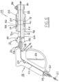
FIG. 5 is a cross-sectional elevational view of a projectile launching apparatus in accordance with the present disclosure, showing a first embodiment of a gas gun; -
FIG. 6 is a partial cross-sectional elevational view of a second embodiment of a gas in accordance with the present disclosure, showing first and second passages passing through the trigger mechanism; -
FIG. 7 is an isometric view from above of a first embodiment of an exit nozzle assembly in accordance with the present disclosure; -
FIG. 8 is an exploded view of the exit nozzle assembly shown inFIG. 7 ; -
FIG. 9 is a isometric view from above of a second embodiment of an exit nozzle assembly in accordance with the present disclosure; -
FIG. 10 is an exploded view of a first embodiment of an assembly for arresting a projectile after exiting a cleaned tube; and -
FIG. 11 is an exploded view of a second embodiment of an assembly for arresting a projectile after exiting a cleaned tube. - Throughout the following description, specific elements are set forth in order to provide a more thorough understanding of the disclosure. However, some embodiments of this disclosure may be practiced without some of these elements. In other instances, well known elements have not been shown or described in detail to avoid unnecessarily obscuring the disclosure. Accordingly, the specification and drawings are to be regarded as illustrative rather than restrictive. It is to be further noted that the drawings may not be to scale.
- Note that various terminology used herein can imply direct or indirect, full or partial, temporary or permanent, action or inaction. For example, when an element is referred to as being "on," "connected," or "coupled" to another element, then the element can be directly on, connected, or coupled to another element or intervening elements can be present, including indirect or direct variants. In contrast, when an element is referred to as being "directly connected" or "directly coupled" to another element, then there are no intervening elements present.
- As used herein, various singular forms "a," "an" and "the" are intended to include various plural forms (e.g., two, three, four, etc.) as well, unless specific context clearly indicates otherwise.
- As used herein, various presence verbs "comprises," "includes" or "comprising," "including" when used in this specification, specify a presence of stated features, integers, steps, operations, elements, or components, but do not preclude the presence or addition of one or more other features, integers, steps, operations, elements, components, or groups thereof.
- As used herein, a term "or" is intended to mean an inclusive "or" rather than an exclusive "or." That is, unless specified otherwise, or clear from context, "X employs A or B" is intended to mean any of a set of natural inclusive permutations. That is, if X employs A; X employs B; or X employs both A and B, then "X employs A or B" is satisfied under any of the foregoing instances.
- As used herein, unless otherwise defined, all terms (including technical and scientific terms) used herein have the same meaning as commonly understood by one of ordinary skill in an art to which this disclosure belongs. Various terms, such as those defined in commonly used dictionaries, should be interpreted as having a meaning that is consistent with a meaning in a context of a relevant art and should not be interpreted in an idealized or overly formal sense unless expressly so defined herein.
- As used herein, relative terms such as "below," "lower," "above," and "upper" can be used herein to describe one element's relationship to another element as illustrated in the set of accompanying illustrative drawings. Such relative terms are intended to encompass different orientations of illustrated technologies in addition to an orientation depicted in the set of accompanying illustrative drawings. For example, if a device in the set of accompanying illustrative drawings were turned over, then various elements described as being on a "lower" side of other elements would then be oriented on "upper" sides of other elements. Similarly, if a device in one of illustrative figures were turned over, then various elements described as "below" or "beneath" other elements would then be oriented "above" other elements. Therefore, various example terms "below" and "lower" can encompass both an orientation of above and below.
- As used herein, a term "about" or "substantially" refers to a +/-10% variation from a nominal value/term. Such variation is always included in any given value/term provided herein, whether or not such variation is specifically referred thereto.
- Features described with respect to certain embodiments may be combined in or with various some embodiments in any permutational or combinatory manner. Different aspects or elements of example embodiments, as disclosed herein, may be combined in a similar manner.
- Although the terms first, second, can be used herein to describe various elements, components, regions, layers, or sections, these elements, components, regions, layers, or sections should not necessarily be limited by such terms. These terms are used to distinguish one element, component, region, layer or section from another element, component, region, layer or section. Thus, a first element, component, region, layer, or section discussed below could be termed a second element, component, region, layer, or section without departing from various teachings of this disclosure.
- Features described with respect to certain example embodiments can be combined and sub-combined in or with various other example embodiments. Also, different aspects or elements of example embodiments, as disclosed herein, can be combined and sub-combined in a similar manner as well. Further, some example embodiments, whether individually or collectively, can be components of a larger system, wherein other procedures can take precedence over or otherwise modify their application. Additionally, a number of steps can be required before, after, or concurrently with example embodiments, as disclosed herein. Note that any or all methods or processes, at least as disclosed herein, can be at least partially performed via at least one entity in any manner.
- Example embodiments of this disclosure are described herein with reference to illustrations of idealized embodiments (and intermediate structures) of this disclosure. As such, variations from various illustrated shapes as a result, for example, of manufacturing techniques or tolerances, are to be expected. Thus, various example embodiments of this disclosure should not be construed as necessarily limited to various particular shapes of regions illustrated herein, but are to include deviations in shapes that result, for example, from manufacturing.
- Any or all elements, as disclosed herein, can be formed from a same, structurally continuous piece, such as being unitary, or be separately manufactured or connected, such as being an assembly or modules. Any or all elements, as disclosed herein, can be manufactured via any manufacturing processes, whether additive manufacturing, subtractive manufacturing, or other any other types of manufacturing. For example, some manufacturing processes include three dimensional (3D) printing, laser cutting, computer numerical control routing, milling, pressing, stamping, vacuum forming, hydroforming, injection molding, lithography, and so forth. Further, the term "projectile" as used herein refers generically to any object or material, whether solid, liquid, or gas expelled from the projectile launching apparatus described and claimed hereinbelow.
- Referring now to
FIGS. 1 through 5 , aprojectile launching apparatus 10 comprises amain body 12, aslide 14 disposed on an exterior surface 16 ofmain body 12, a first embodiment of agas gun 18 operatively connected tomain body 12 via acoupling 20, and anexit nozzle 22 connected tomain body 12 via an exit port 24 inmain body 12. Preferably but not necessarily,main body 12,slide 14,exit nozzle 22, and exit port 24 are cylindrical, which may include a right circular cylinder, an oblique circular cylinder or others. -
Main body 12 is provided with aninternal breech chamber 26, preferably cylindrical, which may include a right circular cylinder, an oblique circular cylinder or others, for receiving a projectile 28 to be launched.Projectile 28 is preferably a soft pellet, such as a urethane foam sponge.Breech chamber 26 is open to the exterior ofmain body 12 by aradial loading port 30 whereby projectile 28 may be entered intobreech chamber 26. -
Slide 14 is preferably a cylinder, which may include a right circular cylinder, an oblique circular cylinder or others, close-fitting on its inner bore to main body exterior surface 16.Axial travel 32 ofslide 14 is limited in afirst direction 34, whereby loadingport 30 is uncovered, by afirst stop 36 disposed in a first circumferential groove in surface 16 that engages a step 38 formed in the bore 40 ofslide 14.Axial travel 32 ofslide 14 is limited in a second andopposite direction 44, whereby loadingport 30 is covered, by asecond stop 46 in the form of a retaining ring disposed in a second circumferential groove in surface 16 that engages anend 48 ofslide 14. For example, slide 14 may be disposed over the exterior surface ofmain body 12 external to breechchamber 26, whereslide 14 can be axially movable between a first position where loadingport 30 is exposed for loading of projectile 28 intobreech chamber 26 and a second position where loadingport 30 andbreech chamber 26 are sealed. - First stop 36 is a first U-cup containing an O-ring for sealing the forward end of
breech chamber 26 against the inner surface ofslide 14; similarly, a second U-cup and O-ring 50 is disposed in a third circumferential groove in surface 16 for sealing the rear end ofbreech chamber 26 against the inner surface ofslide 14. Preferably, the outer surface 52 ofslide 14 is knurled to improve the grip by an operator when opening and closing thebreech chamber 26. - A first embodiment of
gas gun 18 comprises a housing containing a first passage 54 extending between aninlet port 56 and anoutlet port 58. An inlet fitting 60 is disposed ininlet port 56 for connection to asource 61 of a compressed gas, e.g., air. Outlet fitting 20 is disposed inoutlet port 58 for connectingair gun 18 to breechinlet passage 62 inmain body 12. A valve 64, shown schematically in first passage 54, is activated bypivotable trigger 66 to admit compressed gas to breechchamber 26 to fire projectile 26 fromprojectile launching apparatus 10. In the event that the target tube is plugged against passage of the projectile, back pressure 68 in the tube is relieved via asecond passage 70. - Referring now to
FIG. 6 , a second and currently preferred embodiment of anair gun 118 is substantially as disclosed in incorporatedUS Patent No. 6,631,531 B1 .Hand grip 120 is provided with a compressed gas supply passage 122 and apressure relief passage 124, each terminating in acylindrical valve chamber 126 holding atrigger valve assembly 128 having a valve slide 130 slidably disposed within avalve body 132. Valve slide 130 is actuated by trigger knob 134 to control the flow of air fromcompressed gas source 61 to breechchamber 26, and, when required, to ambiance. Valve slide 130 is fitted with aspring recess 136 receiving acoil spring 138. - When air flow
control valve assembly 128 is in the position shown inFIG. 6 , flow of compressed gas from supply passage 122 through the valve is blocked. - When the trigger is pulled, thereby moving the valve slide to the left in
FIG. 6 , the compressed gas flows (line 122a) through the valve interior and intobreech chamber 26 to propel a projectile out of the projectile launcher. Simultaneously, O-ring 140 seals the valve interior wall fromexhaust port 142. When the trigger is released,spring 138 urges valve slide 130 to return to the rest position shown inFIG. 6 , wherein the compressed gas supply is again shut off andexhaust port 142 is opened, allowing return flow (line 124a) frombreech chamber 26 through the valve interior intoexhaust passage 124. - In the event a compressed gas charge propels projectile 28 into a conduit that is blocked preventing passage of the projectile, the air overpressure existing within
breech chamber 26 represents a potentially hazardous situation for an operator. Allowing the chamber pressure to drop to an atmospheric pressure ends the potentially dangerous condition. - Referring again to
FIGS. 1 through 5 , and also 7 through 9,exit nozzle assembly 22 is disposed in exit port 24, preferably via a male/female threaded connection 72 (FIG. 5 ) or other conventional connecting arrangement. - In one embodiment, an
exit nozzle assembly 22 comprises anozzle body 74 having preferably a male-threadedend 76 for connection to exit port 24 and a hose-barb end 78 for receiving a hose/coupling 80 secured to hose-barb end 78 by afirst hose clamp 82. Preferably,nozzle body 74 has a conical inner surface tapering to a diameter smaller than the diameter ofbreech chamber 26 such thatprojectile 28 is radially compressed as projectile 28 passes through the nozzle body.Projectile launcher 10 is secured to atube 84 to be cleaned by inserting the entrance end oftube 84 into hose-coupling 80 and tighteningsecond hose clamp 86. - Other suitable arrangements for coupling hose/
coupling 80 to exit port 24 and tonozzle body 74, e.g., by compression fittings, screw threads, quick connect, welding, etc., may be used. - In another
embodiment 222 of an exit nozzle assembly, with respect tofirst embodiment 22, hose/coupling 80 andsecond hose clamp 86 are replaced by anipple 224 preferably secured tonozzle body 74 byfirst hose clamp 82, or by any of the suitable attachment arrangements cited hereinabove.Nipple 224 has aterminal end 226 smaller in diameter than the entrance end oftube 84 such thatnipple 224 may be sealingly inserted into the entrance end oftube 84 before firing ofprojectile launcher 10. Preferably, theouter surface 228 ofnipple 224 is conically tapered, allowing a single nipple to be used in cleaning a range of tubes having different diameters larger than the diameter ofterminal end 226. Preferably,nipple 224 is formed of a soft polymer or elastomer or another suitable material to enhance the seal withtube entrance 84. Additionally, a range of sizes ofnipples 224 may be provided as needed to increase the range of tube sizes that may be cleaned. - Referring now to
FIGS. 10 and 11 , alternative embodiments 300,400 are shown for catching a projectile and/or fluid and/or debris exiting fromtube 84. - Catching
embodiment 300 comprises acontainer 302; optionally an absorbent material, such as an oil-absorbent towel 304 disposed incontainer 302; a threaded container lid 306; a fitting 308 disposed in an opening in lid 306; ahose 310 extending between vented fitting 308 and the exit end oftube 84; and aclamp 312 for securinghose 310 totube 84. In some applications,hose 310 and clamp 312 may be eliminated and fitting 308 attached directly to the exit end oftube 84.Embodiment 300 includes avent 314, shown as being an element of fitting 308, but may alternatively be formed in any component of the embodiment. - Catching
embodiment 400 comprises acontainer 402; optionally an absorbent material, such as an oil-absorbent towel 404 disposed incontainer 402; a threaded container lid 406; a fitting having a first part 408a disposed in a non-central opening in lid 406 and asecond part 408b engaging first part 408a; ahose 410 extending betweenfitting 408b and the exit end oftube 84; and aclamp 412 for securinghose 410 totube 84. In some applications,hose 410 and clamp 412 may be eliminated and fitting 408b attached directly to the exit end oftube 84.Embodiment 400 includes avent 414 andvent shield 416, shown as being an element of lid 406, but insertable into any component of the embodiment. - Catching
embodiment 400 is distinguished from catchingembodiment 300 in that fitting part 408a extends through lid 406 and includes anelbow bend 409 that causes the path of material being caught to be turned to entercontainer 402 substantially tangential to the inner wall thereof. - In operation, inlet fitting 61 is connected to compressed
gas source 61, then the entrance end oftube 84 to be cleaned is entered into hose/coupling 80 andclamp 86 is tightened.Slide 14 is moved towardtube 84, thereby exposingloading port 30.Projectile 28 is inserted intobreech chamber 26 via loadingport 30.Slide 14 is then moved or axially or laterally slid away fromtube 84, thereby closingloading port 30. Catchingembodiment tube 84. The projectile launcher is now ready to be fired. The trigger is pulled, discharging the projectile 28 into and throughtube 84 into catchingembodiment container 302/402 is unscrewed from its respective cap 306/406, and the captured material is discarded. - This detailed description has been presented for various purposes of illustration and description, but is not intended to be fully exhaustive or limited to this disclosure in various forms disclosed. Many modifications and variations in techniques and structures will be apparent to those of ordinary skill in an art without departing from the scope of this disclosure as set forth in various claims that follow. Accordingly, such modifications and variations are contemplated as being a part of this disclosure. The invention is defined by various claims, which include known equivalents and unforeseeable equivalents at a time of filing of this disclosure..
Claims (19)
- A system, comprising:
a projectile launching apparatus (10) configured to clean an inner surface of a tube (84) by forcing a projectile (28) through the tube (84) along the inner surface, wherein the projectile launching apparatus (10) comprises:a) a main body (12) including an exterior surface (16), wherein the main body (12) contains a breech chamber (26) terminating in an exit port (24), wherein the breech chamber (26) is provided with a loading port (30) in a side thereof for radially loading the projectile (28) into the breech chamber (26);b) a slide (14) disposed over the exterior surface (16) of the main body (12) external to the breech chamber (26), wherein the slide (14) is axially movable between a first position where the loading port (30) is exposed for loading of the projectile (28) into the breech chamber (26), and a second position where the loading port (30) and the breech chamber (26) are sealed;c) an air gun (18, 118) operatively connected to the main body (12) in pneumatic communication with the breech chamber (26); andd) an exit nozzle (22) connected to the exit port (24) and being connectable to the tube (84) to be cleaned, characterized in that the exit nozzle comprises a nozzle body (74) having a threaded end (76) connected to the exit port (24) and a hose-barb end (78), whereby:(i) a hose-coupling (80) is secured to the hose-barb end (78) by a first hose clamp (82), whereby the projectile launching apparatus is securable to the tube (84) having an entrance end for the tube to be cleaned by inserting the entrance end into the hose-coupling (80) and tightening a second hose clamp (86), or(ii) a nipple (224) is secured to the hose-barb end (78) by a first hose clamp (82) , whereby the nipple has a terminal end (226) smaller in diameter than an entrance end of the tube (84) such that the nipple is sealingly insertable into the entrance end before firing of the projectile launcher. - The system in accordance with Claim 1, wherein the main body (12), the breech chamber (26), the exit nozzle (22), and the slide (14) are cylindrical.
- The system in accordance with Claim 2, wherein the exit nozzle (22) has a conical inner surface tapering to a diameter smaller than a diameter of the breech chamber (26).
- The system in accordance with Claim 2, wherein the exit nozzle (22) and the exit port (24) are joined by threads.
- The system in accordance with Claim 4, wherein the exit port (24) comprises female threads and the exit nozzle (22) comprises male threads.
- The system in accordance with Claim 1, wherein the exit nozzle comprises the nozzle body (74) having the threaded end (76) connectable to the exit port and the hose-barb end (78) configured for receiving the hose-coupling (80) securable to the hose-barb end by the first hose clamp (82), whereby the projectile launching apparatus is securable to the tube having the entrance end for the tube to be cleaned by inserting the entrance end into the hose-coupling and tightening the second hose clamp (86).
- The system in accordance with Claim 1, further comprising:
a clamp (82, 86, 312, 412) configured to positively attach the projectile launching apparatus (10) to the tube (84) to be cleaned - The system in accordance with Claim 2, wherein the exit nozzle (22) terminates in a nipple (224) that reduces in width in a direction away from the main body (12).
- The system in accordance with Claim 1, wherein the projectile (28) is in a form of a foam pellet.
- The system in accordance with Claim 9, wherein the projectile (28) is conformable to the inner surface of the tube (84).
- The system in accordance with Claim 1, wherein the air gun (18, 118) comprises:a) a main housing;b) a hand grip (120) having a trigger mechanism attached to the main housing, wherein the trigger mechanism includes a trigger (66);c) a fitting in the hand grip (120) configured for receiving a compressed gas from a source (61);d) a first passage (54) extending from the fitting through the trigger mechanism to the breech chamber (26); ande) a second passage (70) extending from the breech chamber (26) through the trigger mechanism to an exhaust port (140) in the hand grip (120), wherein the first passage (54) is opened to the source (61) and the second passage (70) is closed when the trigger (66) is actuated against an internal spring, and wherein the first passage (54) is closed and the second passage (70) is opened when the trigger (66) is released.
- The system in accordance with Claim 1, further comprising:
an assembly connectable to a second end of the tube (84) for arresting the projectile (28) after exiting the tube (84). - The system in accordance with Claim 12, wherein the assembly including at least a vented container in hydraulic or pneumatic communication with the second end of the tube (84).
- The system in accordance with Claim 13, wherein the vented container includes a removable cap.
- The system in accordance with Claim 14, wherein the assembly includes a hose and a fitting (308), wherein the hose (310, 410) includes a first end portion and a second end portion, wherein the first end portion is connectable to the second end of the tube (84), wherein the fitting is disposed in the removable cap configured for receiving the second end portion of the hose (310, 410).
- The system in accordance with Claim 1, wherein the nipple (224) is securable to the nozzle body (74), whereby the nipple has the terminal end (226) smaller in diameter than the entrance end of the tube such that the nipple is sealingly insertable into the entrance end before firing of the projectile launcher.
- The system in accordance with Claim 14, wherein the removable cap includes a vent port.
- The system in accordance with Claim 14, wherein the removable cap includes an entry port arranged such that the projectile (28) enters the vented container tangentially to an inner wall of the vented container.
- The system in accordance with Claim 13, further comprising: an absorbent material (304, 404) disposed in the vented container
Applications Claiming Priority (1)
| Application Number | Priority Date | Filing Date | Title |
|---|---|---|---|
| US17/074,869 US11203047B1 (en) | 2020-10-20 | 2020-10-20 | Projectile launcher |
Publications (2)
| Publication Number | Publication Date |
|---|---|
| EP3988222A1 EP3988222A1 (en) | 2022-04-27 |
| EP3988222B1 true EP3988222B1 (en) | 2025-01-15 |
Family
ID=78332632
Family Applications (1)
| Application Number | Title | Priority Date | Filing Date |
|---|---|---|---|
| EP21203693.3A Active EP3988222B1 (en) | 2020-10-20 | 2021-10-20 | Projectile launching apparatus configured to clean an inner surface of a tube |
Country Status (5)
| Country | Link |
|---|---|
| US (2) | US11203047B1 (en) |
| EP (1) | EP3988222B1 (en) |
| CA (1) | CA3135080C (en) |
| ES (1) | ES3012457T3 (en) |
| TW (1) | TWI788057B (en) |
Families Citing this family (1)
| Publication number | Priority date | Publication date | Assignee | Title |
|---|---|---|---|---|
| US11203047B1 (en) * | 2020-10-20 | 2021-12-21 | Diversitech Corporation | Projectile launcher |
Family Cites Families (35)
| Publication number | Priority date | Publication date | Assignee | Title |
|---|---|---|---|---|
| US1867751A (en) * | 1929-02-09 | 1932-07-19 | Franklin Dev Company | Gun for condenser cleaning slugs |
| US3631555A (en) * | 1970-03-09 | 1972-01-04 | Combustion Eng | Tube-cleaning pellet gun |
| US4252255A (en) * | 1979-03-13 | 1981-02-24 | David Henderson | Mechanism for purging a plural component mixing and dispensing gun |
| US4467488A (en) * | 1982-12-23 | 1984-08-28 | Combustion Engineering, Inc. | Device for final cleaning of tubes |
| BR9005026A (en) * | 1989-02-08 | 1991-08-06 | Barry Bros Spec Services | PROJECTILE LAUNCHER ADAPTED FOR USE IN A TUBE CLEANING EQUIPMENT, APPLIANCE TO CLEAN A PIPE ASSEMBLY HAVING OPEN ENDS AND A PIPE ASSEMBLY HAVING OPEN ENDS AT LEAST IN ONE END OF THE ASSEMBLY |
| US4974277A (en) | 1989-09-14 | 1990-12-04 | Technic Pty., Ltd. | Pneumatic gun |
| ATE186662T1 (en) * | 1990-08-10 | 1999-12-15 | Compri Technic Pty Ltd | COMPRESSED AIR PISTOL AND BULLET BODY |
| US5139576A (en) * | 1991-03-07 | 1992-08-18 | Western Gas Processors, Ltd. | Method and a horizontal pipeline pig launching mechanism for sequentially launching pipeline pigs |
| DE4223054A1 (en) * | 1992-07-14 | 1994-01-20 | Gema Volstatic Ag St Gallen | Cleaning method for hoses, injectors etc. of powder coating equipment - involves driving one or more oversize sponge plugs through hose with axially aligned compressed air jet whose dia. is less than that of hose |
| US5448795A (en) * | 1994-07-29 | 1995-09-12 | Boughal; Sean | Condenser tube cleaner |
| US5542406A (en) * | 1994-08-22 | 1996-08-06 | Oneto; Michael A. | Retractable bolt assembly for compressed gas powered gun |
| AUPN012694A0 (en) * | 1994-12-16 | 1995-01-19 | Pneumatic Systems International Pty Ltd | Pressure flushing device |
| US5771875A (en) * | 1995-04-28 | 1998-06-30 | Sullivan; Brian E. | Gas powered repeating gun |
| US5586545A (en) * | 1995-10-02 | 1996-12-24 | Mccaslin; John A. | Compressed gas gun |
| US6569255B2 (en) * | 1998-09-24 | 2003-05-27 | On Stream Technologies Inc. | Pig and method for cleaning tubes |
| US20030024520A1 (en) * | 1999-03-19 | 2003-02-06 | Dobbins Jerrold M. | Discharge port and breech for compressed gas gun |
| US20030079731A1 (en) * | 1999-03-19 | 2003-05-01 | Jerry Dobbins | Spring assist for launch from compressed gas gun |
| AUPQ565500A0 (en) * | 2000-02-15 | 2000-03-09 | Symplistic Technologies Limited | Apparatus and method for cleaning a pipe |
| US6631531B1 (en) * | 2000-11-16 | 2003-10-14 | Goodway Technologies Corporation | Quick load air gun |
| US6637420B2 (en) * | 2001-06-29 | 2003-10-28 | Colin Bryan Moritz | Closed bolt assembly for a paintball marker gun |
| US7237545B2 (en) * | 2002-03-06 | 2007-07-03 | Aj Acquisition I Llc | Compressed gas-powered projectile accelerator |
| US7698769B2 (en) * | 2003-02-20 | 2010-04-20 | The Boeing Company | Device to catch and retrieve foam pellets |
| EP1793166B1 (en) * | 2005-12-03 | 2008-06-04 | HNE Technologie AG | Method for the inside cleaning of industrial furnaces, silos and such through bombardment with industrial guns |
| WO2007139934A2 (en) * | 2006-05-25 | 2007-12-06 | Kee Action Sports I Llc | Self-regulating valve assembly |
| US7870852B2 (en) * | 2007-01-19 | 2011-01-18 | Kingman International Corporation | Pneumatically powered projectile launching device |
| US8596255B2 (en) * | 2010-05-10 | 2013-12-03 | Hobbeezone, Inc. | Super absorbent polymer projectile launching device |
| US8146193B1 (en) * | 2010-11-29 | 2012-04-03 | Goodway Technologies Corporation | Launcher for tube cleaning projectiles |
| US8893697B2 (en) * | 2012-01-15 | 2014-11-25 | Mark R Foeller | Multiple soft projectile blow gun |
| EP3011254B1 (en) * | 2013-06-21 | 2019-01-30 | Kee Action Sports I LLC | Compressed gas gun having built-in, internal projectile feed mechanism |
| HK1206925A2 (en) | 2014-09-30 | 2016-01-15 | Alex Brands Buzz Bee Toys (Hk) Limited | Toy gun |
| US9605924B1 (en) * | 2015-10-22 | 2017-03-28 | John A. McCaslin | Compressed gas gun with improved operating mechanism |
| CN105710094A (en) * | 2016-03-21 | 2016-06-29 | 郑州恒锦峰工贸有限公司 | Cleaning device and cleaning method for high-pressure pneumatic pipeline |
| CN111014177B (en) * | 2019-11-26 | 2021-12-10 | 中广核核电运营有限公司 | Sealed section leakage probe cavity purging device and system |
| US11732181B2 (en) * | 2020-01-13 | 2023-08-22 | Riddle's Dehi & Chemical Services Co., Inc. | Method of treating an apparatus to remove surface deposits |
| US11203047B1 (en) * | 2020-10-20 | 2021-12-21 | Diversitech Corporation | Projectile launcher |
-
2020
- 2020-10-20 US US17/074,869 patent/US11203047B1/en active Active
-
2021
- 2021-10-20 TW TW110138871A patent/TWI788057B/en active
- 2021-10-20 ES ES21203693T patent/ES3012457T3/en active Active
- 2021-10-20 CA CA3135080A patent/CA3135080C/en active Active
- 2021-10-20 EP EP21203693.3A patent/EP3988222B1/en active Active
- 2021-12-20 US US17/556,145 patent/US12138672B2/en active Active
Also Published As
| Publication number | Publication date |
|---|---|
| ES3012457T3 (en) | 2025-04-09 |
| US12138672B2 (en) | 2024-11-12 |
| TW202223329A (en) | 2022-06-16 |
| US11203047B1 (en) | 2021-12-21 |
| TWI788057B (en) | 2022-12-21 |
| CA3135080C (en) | 2023-10-10 |
| EP3988222A1 (en) | 2022-04-27 |
| CA3135080A1 (en) | 2022-04-20 |
| US20220118488A1 (en) | 2022-04-21 |
Similar Documents
| Publication | Publication Date | Title |
|---|---|---|
| US8146193B1 (en) | Launcher for tube cleaning projectiles | |
| FI105658B (en) | Improved compressed air gun and projectiles for this | |
| US6766795B1 (en) | Paintball gun having a hinged receiver and method for making same | |
| EP0708909A1 (en) | Paint ball gun | |
| US8087406B2 (en) | Gun using compressed gas to propel an arrow | |
| US9765902B2 (en) | Sanitary high pressure aerator valve assembly | |
| CA3135080C (en) | Projectile launchers and methods of manufacture and use thereof | |
| RS65461B1 (en) | Silencer for fitting to a weapon barrel | |
| US12098901B2 (en) | Gas-powered gun | |
| WO2016051346A1 (en) | Fluid supply apparatus | |
| US6631531B1 (en) | Quick load air gun | |
| US5349982A (en) | Control mechanism for water blasting gun | |
| US11009313B2 (en) | Valve system for air gun | |
| US7533663B2 (en) | Pneumatic paintball gun | |
| US20240159492A1 (en) | Gas-powered gun | |
| US12017260B2 (en) | Systems and methods for belt-fed tube cleaning | |
| US11236958B2 (en) | Tube cleaning gun with self-sealing nozzle | |
| US20130112286A1 (en) | Quick-connect coupling | |
| DE102014103098B4 (en) | Compressed gas weapon | |
| EP1183111A1 (en) | Apparatus and method for cleaning a pipe | |
| AU2006202069A1 (en) | Apparatus and Method for Cleaning a Pipe | |
| SE449952B (en) | Applicator for pipe cleaning pig | |
| AU3349501A (en) | Apparatus and method for cleaning a pipe | |
| AU8333891A (en) | Improved pneumatic gun and projectiles therefor |
Legal Events
| Date | Code | Title | Description |
|---|---|---|---|
| PUAI | Public reference made under article 153(3) epc to a published international application that has entered the european phase |
Free format text: ORIGINAL CODE: 0009012 |
|
| STAA | Information on the status of an ep patent application or granted ep patent |
Free format text: STATUS: THE APPLICATION HAS BEEN PUBLISHED |
|
| AK | Designated contracting states |
Kind code of ref document: A1 Designated state(s): AL AT BE BG CH CY CZ DE DK EE ES FI FR GB GR HR HU IE IS IT LI LT LU LV MC MK MT NL NO PL PT RO RS SE SI SK SM TR |
|
| STAA | Information on the status of an ep patent application or granted ep patent |
Free format text: STATUS: REQUEST FOR EXAMINATION WAS MADE |
|
| 17P | Request for examination filed |
Effective date: 20220822 |
|
| RBV | Designated contracting states (corrected) |
Designated state(s): AL AT BE BG CH CY CZ DE DK EE ES FI FR GB GR HR HU IE IS IT LI LT LU LV MC MK MT NL NO PL PT RO RS SE SI SK SM TR |
|
| STAA | Information on the status of an ep patent application or granted ep patent |
Free format text: STATUS: EXAMINATION IS IN PROGRESS |
|
| 17Q | First examination report despatched |
Effective date: 20230724 |
|
| GRAP | Despatch of communication of intention to grant a patent |
Free format text: ORIGINAL CODE: EPIDOSNIGR1 |
|
| STAA | Information on the status of an ep patent application or granted ep patent |
Free format text: STATUS: GRANT OF PATENT IS INTENDED |
|
| INTG | Intention to grant announced |
Effective date: 20240902 |
|
| RIC1 | Information provided on ipc code assigned before grant |
Ipc: F41B 11/87 20130101ALI20240823BHEP Ipc: F41A 29/00 20060101ALI20240823BHEP Ipc: B08B 9/055 20060101AFI20240823BHEP |
|
| GRAS | Grant fee paid |
Free format text: ORIGINAL CODE: EPIDOSNIGR3 |
|
| GRAA | (expected) grant |
Free format text: ORIGINAL CODE: 0009210 |
|
| STAA | Information on the status of an ep patent application or granted ep patent |
Free format text: STATUS: THE PATENT HAS BEEN GRANTED |
|
| P01 | Opt-out of the competence of the unified patent court (upc) registered |
Free format text: CASE NUMBER: APP_63703/2024 Effective date: 20241201 |
|
| AK | Designated contracting states |
Kind code of ref document: B1 Designated state(s): AL AT BE BG CH CY CZ DE DK EE ES FI FR GB GR HR HU IE IS IT LI LT LU LV MC MK MT NL NO PL PT RO RS SE SI SK SM TR |
|
| REG | Reference to a national code |
Ref country code: CH Ref legal event code: EP Ref country code: GB Ref legal event code: FG4D |
|
| REG | Reference to a national code |
Ref country code: DE Ref legal event code: R096 Ref document number: 602021024905 Country of ref document: DE |
|
| REG | Reference to a national code |
Ref country code: IE Ref legal event code: FG4D |
|
| REG | Reference to a national code |
Ref country code: ES Ref legal event code: FG2A Ref document number: 3012457 Country of ref document: ES Kind code of ref document: T3 Effective date: 20250409 |
|
| REG | Reference to a national code |
Ref country code: NL Ref legal event code: MP Effective date: 20250115 |
|
| PG25 | Lapsed in a contracting state [announced via postgrant information from national office to epo] |
Ref country code: NL Free format text: LAPSE BECAUSE OF FAILURE TO SUBMIT A TRANSLATION OF THE DESCRIPTION OR TO PAY THE FEE WITHIN THE PRESCRIBED TIME-LIMIT Effective date: 20250115 |
|
| PG25 | Lapsed in a contracting state [announced via postgrant information from national office to epo] |
Ref country code: RS Free format text: LAPSE BECAUSE OF FAILURE TO SUBMIT A TRANSLATION OF THE DESCRIPTION OR TO PAY THE FEE WITHIN THE PRESCRIBED TIME-LIMIT Effective date: 20250415 |
|
| PG25 | Lapsed in a contracting state [announced via postgrant information from national office to epo] |
Ref country code: FI Free format text: LAPSE BECAUSE OF FAILURE TO SUBMIT A TRANSLATION OF THE DESCRIPTION OR TO PAY THE FEE WITHIN THE PRESCRIBED TIME-LIMIT Effective date: 20250115 |
|
| PG25 | Lapsed in a contracting state [announced via postgrant information from national office to epo] |
Ref country code: PL Free format text: LAPSE BECAUSE OF FAILURE TO SUBMIT A TRANSLATION OF THE DESCRIPTION OR TO PAY THE FEE WITHIN THE PRESCRIBED TIME-LIMIT Effective date: 20250115 |
|
| REG | Reference to a national code |
Ref country code: LT Ref legal event code: MG9D |
|
| PG25 | Lapsed in a contracting state [announced via postgrant information from national office to epo] |
Ref country code: IS Free format text: LAPSE BECAUSE OF FAILURE TO SUBMIT A TRANSLATION OF THE DESCRIPTION OR TO PAY THE FEE WITHIN THE PRESCRIBED TIME-LIMIT Effective date: 20250515 Ref country code: NO Free format text: LAPSE BECAUSE OF FAILURE TO SUBMIT A TRANSLATION OF THE DESCRIPTION OR TO PAY THE FEE WITHIN THE PRESCRIBED TIME-LIMIT Effective date: 20250415 |
|
| REG | Reference to a national code |
Ref country code: AT Ref legal event code: MK05 Ref document number: 1759504 Country of ref document: AT Kind code of ref document: T Effective date: 20250115 |
|
| PG25 | Lapsed in a contracting state [announced via postgrant information from national office to epo] |
Ref country code: HR Free format text: LAPSE BECAUSE OF FAILURE TO SUBMIT A TRANSLATION OF THE DESCRIPTION OR TO PAY THE FEE WITHIN THE PRESCRIBED TIME-LIMIT Effective date: 20250115 |
|
| PG25 | Lapsed in a contracting state [announced via postgrant information from national office to epo] |
Ref country code: LV Free format text: LAPSE BECAUSE OF FAILURE TO SUBMIT A TRANSLATION OF THE DESCRIPTION OR TO PAY THE FEE WITHIN THE PRESCRIBED TIME-LIMIT Effective date: 20250115 Ref country code: PT Free format text: LAPSE BECAUSE OF FAILURE TO SUBMIT A TRANSLATION OF THE DESCRIPTION OR TO PAY THE FEE WITHIN THE PRESCRIBED TIME-LIMIT Effective date: 20250515 |
|
| PG25 | Lapsed in a contracting state [announced via postgrant information from national office to epo] |
Ref country code: BG Free format text: LAPSE BECAUSE OF FAILURE TO SUBMIT A TRANSLATION OF THE DESCRIPTION OR TO PAY THE FEE WITHIN THE PRESCRIBED TIME-LIMIT Effective date: 20250115 Ref country code: GR Free format text: LAPSE BECAUSE OF FAILURE TO SUBMIT A TRANSLATION OF THE DESCRIPTION OR TO PAY THE FEE WITHIN THE PRESCRIBED TIME-LIMIT Effective date: 20250416 |
|
| PG25 | Lapsed in a contracting state [announced via postgrant information from national office to epo] |
Ref country code: AT Free format text: LAPSE BECAUSE OF FAILURE TO SUBMIT A TRANSLATION OF THE DESCRIPTION OR TO PAY THE FEE WITHIN THE PRESCRIBED TIME-LIMIT Effective date: 20250115 |
|
| PG25 | Lapsed in a contracting state [announced via postgrant information from national office to epo] |
Ref country code: SE Free format text: LAPSE BECAUSE OF FAILURE TO SUBMIT A TRANSLATION OF THE DESCRIPTION OR TO PAY THE FEE WITHIN THE PRESCRIBED TIME-LIMIT Effective date: 20250115 |
|
| PG25 | Lapsed in a contracting state [announced via postgrant information from national office to epo] |
Ref country code: SM Free format text: LAPSE BECAUSE OF FAILURE TO SUBMIT A TRANSLATION OF THE DESCRIPTION OR TO PAY THE FEE WITHIN THE PRESCRIBED TIME-LIMIT Effective date: 20250115 |
|
| PG25 | Lapsed in a contracting state [announced via postgrant information from national office to epo] |
Ref country code: DK Free format text: LAPSE BECAUSE OF FAILURE TO SUBMIT A TRANSLATION OF THE DESCRIPTION OR TO PAY THE FEE WITHIN THE PRESCRIBED TIME-LIMIT Effective date: 20250115 |
|
| PGFP | Annual fee paid to national office [announced via postgrant information from national office to epo] |
Ref country code: IT Payment date: 20250922 Year of fee payment: 5 |
|
| PGFP | Annual fee paid to national office [announced via postgrant information from national office to epo] |
Ref country code: GB Payment date: 20250828 Year of fee payment: 5 |
|
| REG | Reference to a national code |
Ref country code: DE Ref legal event code: R097 Ref document number: 602021024905 Country of ref document: DE |
|
| PGFP | Annual fee paid to national office [announced via postgrant information from national office to epo] |
Ref country code: FR Payment date: 20250821 Year of fee payment: 5 |
|
| PG25 | Lapsed in a contracting state [announced via postgrant information from national office to epo] |
Ref country code: CZ Free format text: LAPSE BECAUSE OF FAILURE TO SUBMIT A TRANSLATION OF THE DESCRIPTION OR TO PAY THE FEE WITHIN THE PRESCRIBED TIME-LIMIT Effective date: 20250115 Ref country code: EE Free format text: LAPSE BECAUSE OF FAILURE TO SUBMIT A TRANSLATION OF THE DESCRIPTION OR TO PAY THE FEE WITHIN THE PRESCRIBED TIME-LIMIT Effective date: 20250115 |
|
| PG25 | Lapsed in a contracting state [announced via postgrant information from national office to epo] |
Ref country code: RO Free format text: LAPSE BECAUSE OF FAILURE TO SUBMIT A TRANSLATION OF THE DESCRIPTION OR TO PAY THE FEE WITHIN THE PRESCRIBED TIME-LIMIT Effective date: 20250115 |
|
| PG25 | Lapsed in a contracting state [announced via postgrant information from national office to epo] |
Ref country code: SK Free format text: LAPSE BECAUSE OF FAILURE TO SUBMIT A TRANSLATION OF THE DESCRIPTION OR TO PAY THE FEE WITHIN THE PRESCRIBED TIME-LIMIT Effective date: 20250115 |
|
| PLBE | No opposition filed within time limit |
Free format text: ORIGINAL CODE: 0009261 |
|
| STAA | Information on the status of an ep patent application or granted ep patent |
Free format text: STATUS: NO OPPOSITION FILED WITHIN TIME LIMIT |
|
| 26N | No opposition filed |
Effective date: 20251016 |
|
| PGFP | Annual fee paid to national office [announced via postgrant information from national office to epo] |
Ref country code: DE Payment date: 20250827 Year of fee payment: 5 |
|
| PGFP | Annual fee paid to national office [announced via postgrant information from national office to epo] |
Ref country code: ES Payment date: 20251107 Year of fee payment: 5 |