EP3987958A1 - Atomization assembly, and electronic cigarette - Google Patents
Atomization assembly, and electronic cigarette Download PDFInfo
- Publication number
- EP3987958A1 EP3987958A1 EP20831642.2A EP20831642A EP3987958A1 EP 3987958 A1 EP3987958 A1 EP 3987958A1 EP 20831642 A EP20831642 A EP 20831642A EP 3987958 A1 EP3987958 A1 EP 3987958A1
- Authority
- EP
- European Patent Office
- Prior art keywords
- liquid
- atomizing
- disposed
- base
- atomizing assembly
- Prior art date
- Legal status (The legal status is an assumption and is not a legal conclusion. Google has not performed a legal analysis and makes no representation as to the accuracy of the status listed.)
- Granted
Links
Images




Classifications
-
- A—HUMAN NECESSITIES
- A24—TOBACCO; CIGARS; CIGARETTES; SIMULATED SMOKING DEVICES; SMOKERS' REQUISITES
- A24F—SMOKERS' REQUISITES; MATCH BOXES; SIMULATED SMOKING DEVICES
- A24F40/00—Electrically operated smoking devices; Component parts thereof; Manufacture thereof; Maintenance or testing thereof; Charging means specially adapted therefor
- A24F40/40—Constructional details, e.g. connection of cartridges and battery parts
- A24F40/48—Fluid transfer means, e.g. pumps
- A24F40/485—Valves; Apertures
-
- A—HUMAN NECESSITIES
- A24—TOBACCO; CIGARS; CIGARETTES; SIMULATED SMOKING DEVICES; SMOKERS' REQUISITES
- A24F—SMOKERS' REQUISITES; MATCH BOXES; SIMULATED SMOKING DEVICES
- A24F15/00—Receptacles or boxes specially adapted for cigars, cigarettes, simulated smoking devices or cigarettes therefor
- A24F15/01—Receptacles or boxes specially adapted for cigars, cigarettes, simulated smoking devices or cigarettes therefor specially adapted for simulated smoking devices or cigarettes therefor
- A24F15/015—Receptacles or boxes specially adapted for cigars, cigarettes, simulated smoking devices or cigarettes therefor specially adapted for simulated smoking devices or cigarettes therefor with means for refilling of liquid inhalable precursors
-
- A—HUMAN NECESSITIES
- A24—TOBACCO; CIGARS; CIGARETTES; SIMULATED SMOKING DEVICES; SMOKERS' REQUISITES
- A24F—SMOKERS' REQUISITES; MATCH BOXES; SIMULATED SMOKING DEVICES
- A24F40/00—Electrically operated smoking devices; Component parts thereof; Manufacture thereof; Maintenance or testing thereof; Charging means specially adapted therefor
- A24F40/10—Devices using liquid inhalable precursors
-
- A—HUMAN NECESSITIES
- A24—TOBACCO; CIGARS; CIGARETTES; SIMULATED SMOKING DEVICES; SMOKERS' REQUISITES
- A24F—SMOKERS' REQUISITES; MATCH BOXES; SIMULATED SMOKING DEVICES
- A24F40/00—Electrically operated smoking devices; Component parts thereof; Manufacture thereof; Maintenance or testing thereof; Charging means specially adapted therefor
- A24F40/40—Constructional details, e.g. connection of cartridges and battery parts
- A24F40/42—Cartridges or containers for inhalable precursors
-
- A—HUMAN NECESSITIES
- A24—TOBACCO; CIGARS; CIGARETTES; SIMULATED SMOKING DEVICES; SMOKERS' REQUISITES
- A24F—SMOKERS' REQUISITES; MATCH BOXES; SIMULATED SMOKING DEVICES
- A24F40/00—Electrically operated smoking devices; Component parts thereof; Manufacture thereof; Maintenance or testing thereof; Charging means specially adapted therefor
- A24F40/40—Constructional details, e.g. connection of cartridges and battery parts
- A24F40/44—Wicks
-
- A—HUMAN NECESSITIES
- A24—TOBACCO; CIGARS; CIGARETTES; SIMULATED SMOKING DEVICES; SMOKERS' REQUISITES
- A24F—SMOKERS' REQUISITES; MATCH BOXES; SIMULATED SMOKING DEVICES
- A24F40/00—Electrically operated smoking devices; Component parts thereof; Manufacture thereof; Maintenance or testing thereof; Charging means specially adapted therefor
- A24F40/40—Constructional details, e.g. connection of cartridges and battery parts
- A24F40/46—Shape or structure of electric heating means
Definitions
- the present invention relates to a technical field of electronic cigarette equipment, particularly relates to an atomizing assembly and an electronic cigarette including the atomizing assembly.
- an electronic cigarette in some electronic cigarette products, includes a battery assembly and an atomization assembly.
- the battery assembly is electrically connected to the atomization assembly. As a result, the battery assembly supplies power to the atomization assembly.
- Liquid tobacco with high viscosity has problem such that a liquid conducting process of the liquid tobacco is slow, and therefore the slow process leads to too little aerosol being generated.
- a viscosity of the liquid tobacco decreases.
- a velocity of conducting the liquid tobacco increases, and the increased conducting velocity leads to problem such as increase of an amount of conducted liquid tobacco, etc. Therefore, the liquid tobacco with high viscosity has technical problem during its heating and atomization process.
- the technical problem includes inconvenient control of the amount of conducted liquid tobacco, and an unreasonable amount of conducted liquid tobacco, etc. As a result, physical experienced feeling regarding actual products is directly affected by the above problem.
- An atomizing assembly and an electronic cigarette having the atomizing assembly are provided in accordance with a preferred embodiment of the present invention.
- Technical problem of existing technology that an amount of conducted liquid tobacco is not conveniently controlled can be solved based on the above atomizing assembly in accordance with the preferred embodiment of the present invention.
- An atomizing assembly applicable to electronic cigarettes includes a base and an atomizing core.
- a liquid storing cavity is disposed inside the base to store liquid tobacco.
- the atomizing core is installed in the base.
- the atomizing core includes a body and a heater.
- An atomizing channel is opened and disposed to penetrate through the body.
- the heater is disposed on an inner wall of the atomizing channel.
- the body is made from porous materials.
- An outer sidewall of the body includes at least an absorbing face.
- a liquid conducting hole or a plurality of liquid conducting holes is opened and disposed on the absorbing face and extends into a wall of the body from the absorbing face.
- a bottom of the liquid conducting hole or the plurality of liquid conducting holes is located inside the wall of the body. The liquid tobacco stored in the liquid storing cavity flows into the body via the absorbing face.
- the base is disposed along a longitudinal direction of the atomizing assembly.
- An extension direction of the atomizing channel is perpendicular to the longitudinal direction of the atomizing assembly.
- an airflow channel is further disposed inside the base.
- the airflow channel is spatially communicated with the atomizing channel.
- the atomizing assembly further includes a nozzle shell.
- a through hole is disposed to penetrate through the nozzle shell.
- the nozzle shell is installed at a side of the base facing away from the atomizing core.
- the through hole is spatially communicate with the atomizing channel via the airflow channel.
- shortest conducting distances between respective bottoms of the plurality of liquid conducting holes and the inner wall of the atomizing channel are set to be equal to one another.
- a hole diameter of each of the liquid conducting hole or the plurality of liquid conducting holes is set to be larger than an average pore diameter of micro pores inside the body.
- the absorbing face is disposed corresponding to the liquid storing cavity.
- the absorbing face is a flat face.
- the liquid conducting hole or the plurality of liquid conducting holes is a plurality of liquid conducting holes, and the plurality of liquid conducting holes is evenly spaced and distributed on the absorbing face.
- the base further includes a liquid filling hole and a liquid outlet.
- the liquid filling hole is spatially communicated with the liquid storing cavity.
- the liquid filling hole and the liquid outlet are respectively located on two opposite lateral walls of the liquid storing cavity.
- the liquid outlet is spatially communicated with the liquid conducting hole or the plurality of liquid conducting holes.
- the atomizing assembly further includes a supporter and an end cover.
- the supporter is located at a side of the base.
- a fixing trough is opened and disposed at a side of the supporter facing toward the base. A part of the body is received in the fixing trough.
- the end cover is disposed between the base and the supporter. Another part of the body is covered around by the end cover. The end cover is fixed connected with the supporter. The end cover is engaged with the base. A communicating hole penetrating through the end cover is opened and disposed at the end cover. The liquid outlet is spatially communicated with the liquid conducting hole or the plurality of liquid conducting holes via the communicating hole.
- a first installing trough is disposed at a side of the base facing toward the supporter.
- the liquid outlet is opened and disposed at a bottom of the first installing trough.
- the end cover is installed in the first installing trough, and the communicating hole is spatially communicated with the liquid outlet.
- the atomizing assembly further includes a connecting seat.
- the connecting seat is installed to the base.
- a lateral wall of the connecting seat and a lateral wall of the base are fixedly connected with each other.
- An accommodating space is formed and surrounded between the connecting seat and the base. The atomizing core is accommodated in the accommodating space.
- a second installing trough is disposed at a side of the connecting seat facing toward the base.
- the supporter is installed in the second installing trough.
- An electronic cigarette in accordance with a preferred embodiment of the present invention is further provided to include the following.
- a battery assembly is installed with the atomizing assembly and is electrically connected with the atomizing assembly.
- a liquid conducting hole or a plurality of liquid conducting holes is opened and disposed on the absorbing face of the body.
- liquid conducting holes with various forms can be disposed and opened on a lateral wall of the body based on user's requirement in order to much conveniently control a liquid conducting process of liquid tobacco.
- liquid tobacco enters the body through the absorbing face. A contact area between the liquid tobacco and the absorbing face is large to facilitate control of an amount of conducted liquid tobacco.
- the term of "installation” means to include methods, such as welding, screwing, clamping, bonding, etc., in order to fix or restrict a certain element or device to a specific position or place.
- the element or device can be held still in a specific position or place, or can be restricted to move within a limited range.
- the element or device can be disassembled or cannot be disassembled after being fixed or restricted to a specific position or place. The above is not limited in embodiments of the present application.
- an electronic cigarette 300 in accordance with a preferred embodiment of the present invention is provided.
- the electronic cigarette 300 includes a battery assembly 200 and an atomizing assembly 100.
- the battery assembly 200 is installed at an end of the atomizing assembly 100 in order to shape the electronic cigarette 300 as a straight-lined structure.
- the battery assembly 200 and the atomizing assembly 100 are fixedly installed together via engaging connection and/or screw fixing connection.
- the battery assembly 200 is electrically connected with the atomizing assembly 100.
- the battery assembly 200 is used to supply power to the atomizing assembly 100 so that the atomizing assembly 100 is able to atomize liquid tobacco into aerosols for users to inhale.
- the atomizing assembly 100 includes a nozzle shell 10, a base 20 and a connecting seat 30.
- the nozzle shell 10, the base 20 and the connecting seat 30 are fixedly connected in sequence to form a straight-lined structure.
- the nozzle shell 10, the base 20 and the connecting seat 30 are all disposed along a longitudinal direction a of the atomizing assembly 100.
- the battery assembly 200 is installed at an end of the connecting seat 30 spaced away from the base 20.
- the nozzle shell 10 is shaped as a cover.
- the base 20 is substantially shaped as a hexahedron.
- the nozzle shell 10 covers around outside an end of the base 20.
- a through hole 11 is disposed to penetrate through a top of the nozzle shell 10.
- An airflow channel 21 is disposed inside the base 20 or at a lateral side of the base 20. When the nozzle shell 10 covers around outside the end of the base 20, the through hole 11 is spatially communicated with the airflow channel 21.
- the airflow channel 21 is straightly disposed along a lateral wall of the base 20.
- the airflow channel 21 extends along a direction parallel to the longitudinal direction a of the atomizing assembly 100.
- a protrusion 22 is disposed to protrude at a lateral side of the base 20.
- An engaging notch 12 is disposed at a lateral side of the nozzle shell 10 corresponding to the protrusion 22.
- a liquid storing cavity 24 is disposed inside the base 20.
- a liquid filling hole 241 is disposed to be opened at the top of the base 20 and is spatially communicated with the liquid storing cavity 24. Alternatively, the liquid filling hole 241 is located in a position corresponding to the through hole 11. Understandably, the atomizing assembly 100 further includes a seal 2411.
- the seal 2411 is used to seal and block the liquid filling hole 241. When the nozzle shell 10 is opened and removed by a user, the seal 2411 can be seen by the user. After the seal 2411 is opened and removed by the user, liquid tobacco can be filled into the liquid storing cavity 24 via the liquid filling hole 241.
- a liquid outlet 242 is disposed to be opened at a bottom of the base 20 and to be spatially communicated with the liquid storing cavity 24.
- the liquid outlet 242 is used to conduct liquid tobacco in the liquid storing cavity 24 out of the liquid storing cavity 24.
- the liquid outlet 242 and the liquid filling hole 241 are respectively located on two opposite lateral walls of the liquid storing cavity 24.
- the connecting seat 30 is installed at the bottom of the base 20.
- the connecting seat 30 and the base 20 are connected to each other via an engaging fixing connection.
- a lateral wall of the base 20 and a lateral wall of the connecting seat 30 are engaged and fixedly connected with each other.
- An accommodating space 40 (As shown in FIG. 3 ) is surrounded between the base 20 and the connecting seat 30.
- a hook or a plurality of hooks 23 is formed to extend from a side of a lateral wall of the base 20 facing toward the connecting seat 30.
- a groove or a plurality of groove 33 is disposed to be opened at a lateral wall of the connecting seat 30 corresponding to the hook or the plurality of hooks 23.
- the hook or the plurality of hooks 23 and the groove or the plurality of groove 33 are one-to-one corresponded to and mated with each other.
- the hook or the plurality of hooks 23 is inserted into the groove or the plurality of groove 33 correspondingly to be secured and fixed therein.
- the atomizing assembly 100 further includes an atomizing core 50, an end cover 61 and a supporter 62.
- the atomizing core 50 is accommodated in the accommodating space 40.
- the atomizing core 50 includes a body 51.
- the body 51 is installed on the supporter 62.
- the end cover 61 is disposed around the body 51 and is fixedly connected with the supporter 62 in order to seal and fix the body 51.
- a connection between the end cover 61 and the supporter 62 can be an integrally formed connection, a fixedly engaging connection, or a screw fixing connection, etc.
- a first installing trough 25 is disposed at a side of the bottom of the base 20 facing toward the connecting seat 30.
- a second installing trough 34 is disposed at a side of the connecting seat 30 facing toward the base 20.
- the first installing trough 25 and the second installing trough are correspondingly disposed to match with each other in order to fixedly install the atomizing core 50 therebetween.
- a top of the end cover 61 is shaped similarly to the first installing trough 25, and the top of the end cover 61 is sealed and installed in the first installing trough 25.
- a bottom of the supporter 62 is shaped similarly to the second installing trough 34, and the bottom of the supporter 62 is installed in the second installing trough 34.
- the liquid outlet 242 is opened and disposed at a bottom of the first installing trough 25.
- a communicating hole 611 penetrating through the end cover 61 is opened and disposed at an end of the end cover 61 neighboring the liquid outlet 242, and the communicating hole 611 is spatially communicated with the liquid outlet 242.
- the communicating hole 611 is opened and disposed at the top of the end cover 61. Liquid tobacco in the liquid storing cavity 24 can flow in sequence through the liquid outlet 242 and the communicating hole 611 to enter the body 51.
- an atomizing channel 513 is opened and disposed to penetrate through the body 51.
- the atomizing channel 513 extends horizontally.
- the atomizing channel 513 is shaped as a straight line.
- the atomizing channel 513 is shaped as a cylinder.
- the atomizing core 50 further includes a heater 52 disposed in the atomizing channel 513.
- the heater 52 is disposed on an inner wall of the atomizing channel 513.
- the heater 52 is coiled around on the inner wall of the atomizing channel 513, is embedded in the inner wall of the atomizing channel 513, or is partially embedded in the inner wall of the atomizing channel 513 and partially exposed out in the atomizing channel 513. Understandably, the heater 52 is an electrically powered heating body. In a condition of electrification, the heater 52 is heated to raise its temperature. For example, the heater 52 is an electric heating wire.
- the body 51 is made from a porous material having a micro-pore structure.
- the body 51 is made from micro-pore ceramic, micro-pore glass or expanded foam materials, etc.
- Liquid tobacco is conducted to the atomizing channel 513 through porous material via capillary effect. Under heating of the heater 52 to raise its temperature, the liquid tobacco is atomized as aerosols to enter the atomizing channel 513.
- An outer sidewall of the body 51 includes at least an absorbing face 511.
- the absorbing face 511 is a flat face.
- the absorbing face 511 is disposed corresponding to the liquid storing cavity 24, and faces toward the communicating hole 611.
- a liquid conducting hole or a plurality of liquid conducting holes 512 is opened and disposed on the absorbing face 511, and extends into a wall of the body 51 from the absorbing face 511.
- a bottom of the liquid conducting hole or the plurality of liquid conducting holes 512 is located inside the wall of the body 51. For instance, a plurality of liquid conducting holes 512 is provided and disposed, and is evenly spaced and distributed on the absorbing face 511.
- shortest conducting distances between bottoms of the plurality of liquid conducting holes 512 and the atomizing channel 513 are respectively set to be equal or substantially equal to one another.
- the plurality of liquid conducting holes 512 is used to conduct liquid tobacco in the liquid storing cavity 24 into the body 51.
- an extension direction of the atomizing channel 513 is perpendicular to the longitudinal direction a of the atomizing assembly 100.
- the absorbing face 511 opened and disposed with the liquid conducting hole or the plurality of liquid conducting holes 512 has a large area, i.e., a contact area for the liquid tobacco to enter the atomizing core 50 is large. Conducted liquid tobacco is facilitated to be controlled by the above mentioned structure.
- liquid tobacco in the liquid storing cavity 24 flows in sequence through the liquid outlet 242, the communicating hole 611 and the liquid conducting hole or a plurality of liquid conducting holes 512 to enter the body 51. Under heating of the heater 52 to raise its temperature, the liquid tobacco is heated and atomized into aerosols to enter the atomizing channel 513.
- the body 51 is made from porous materials having a preset porosity.
- Porosity of a porous material is decided by pore diameters of micro pores inside the porous material and a distribution density of the micro pores.
- the porosity of the porous material is designed to be smaller, performance of the body 51 to prevent liquid tobacco from leaking can therefore be enhanced.
- smaller porosity will lower a conducting velocity of liquid tobacco at the same time.
- a porous material with a proper porosity is required to be selected.
- the liquid conducting hole or the plurality of liquid conducting holes 512 is opened and disposed on the body 51, and a hole diameter of the liquid conducting hole or the plurality of liquid conducting holes 512 is set to be larger than an average pore diameter of micro pores inside a material of the body 51.
- the conducting velocity of the liquid tobacco can be raised, and the performance of the body 51 enough to prevent the liquid tobacco from leaking can also be ensured to be enhanced.
- the average pore diameter of the micro pores inside the material of the body 51 is 10 ⁇ m ⁇ 100 ⁇ m, for example, preferably is 80 ⁇ m.
- the hole diameter of the liquid conducting hole or the plurality of liquid conducting holes 512 is 10 ⁇ m ⁇ 500 ⁇ m, for example, preferably is 100 ⁇ m.
- the hole diameter of the liquid conducting hole or the plurality of liquid conducting holes 512 is larger than the average pore diameter of the micro pores inside the body 51, and a viscosity of liquid tobacco is higher, the liquid tobacco can enter the liquid conducting hole or the plurality of liquid conducting holes 512 having a larger hole diameter in order to have the liquid tobacco being conducted smoothly. After the liquid tobacco is heated to raise its temperature, the viscosity of the liquid tobacco is reduced. At this moment, the liquid tobacco enters the micro pores inside the body 51having a smaller pore diameter. Hence, an amount of conducted liquid tobacco can be effectively controlled.
- the liquid tobacco is finally atomized by the heater 52 into aerosols to enter the atomizing channel 513.
- the body 51 of a preferred embodiment of the present invention is designed to have a better performance to conduct liquid tobacco into the body 41. Particularly, for tobacco liquid with a higher viscosity, the body 51 of the present invention has a better liquid conductive effect. Meanwhile, the body 51 of the present invention can achieve a better control on conducting liquid tobacco so as to avoid technical problem of having an excessively large amount of conducted liquid tobacco during a process of heating and atomizing.
- a fixing trough 621 is opened and disposed at a top of the supporter 62.
- the body 51 is transversely installed in the fixing trough 621.
- the body 51 is transversely installed in the fixing trough 621 and a channel extension direction of the atomizing channel 513 is perpendicular to the longitudinal direction a of the atomizing assembly 100.
- a first opening 6211 is disposed at an end of the fixing trough 621, and a second opening 6212 is disposed at another end of the fixing trough 621.
- the first opening 6211 is disposed corresponding to an end opening of the atomizing channel 513.
- the second opening 6212 is disposed corresponding to another end opening of the atomizing channel 513.
- the supporter 62 includes an extending wall 622 formed by extending outwards from an end of the supporter 62 having the first opening 6211.
- the extending wall 622 is engaged at a lateral wall of the second installing trough 34.
- a connective trough 6221 (Shown in FIG. 3 ) is formed and surrounded by the extending wall 622 and the base 20. Two ends of the connective trough 6221 are respectively spatially communicated with the airflow channel 21 and the first opening 6211. In other words, the airflow channel 21, the connective trough 6221, the first opening 6211, the atomizing channel 513 and the second opening 6212 are spatially communicated with one another in sequence.
- a first airflow trough 623 is formed by extending outwards from an end of the supporter 62 having the second opening 6212.
- the first airflow trough 623 is spatially communicated with the second opening 6212.
- a second airflow trough 32 is disposed in the connecting seat 30.
- the second airflow trough 32 is spatially communicated with the first airflow trough 623.
- the second airflow trough 32 penetrates through the connecting seat 30.
- the second airflow trough 32 is shaped as a straight line, and an extending direction of the second airflow trough 32 is parallel to the longitudinal direction a of the atomizing assembly 100.
- the second airflow trough 32 and the first airflow trough 623 are located at a same side of the atomizing assembly 100.
- the through hole 11, the airflow channel 21, the connective trough 6221, the first opening 6211, the atomizing channel 513, the second opening 6212, the first airflow trough 623 and the second airflow trough 32 are spatially communicated with one another in sequence. Aerosols formed and existing in the atomizing channel 513 can therefore be inhaled by users via the through hole 11.
- electrodes 31 are disposed at the connecting seat 30.
- the battery assembly 200 is located at an end of the connecting seat 30 spaced away from the base 20.
- the connecting seat 30 is fixedly connected with the base 20
- the battery assembly 200 is electrically connected with the heater 52 via the electrodes 31 in order to supply power to the atomizing assembly 100 so that the atomizing assembly 100 is able to atomize liquid tobacco.
- two electrodes 31 are disposed at the connecting seat 30. An end of each of the electrodes 31 is electrically connected with the heater 52, and another end of the each of the electrodes 31 is electrically connected with the battery assembly 200.
- a technical solution of the present invention includes, but is not limited to include, the following advantages.
- a liquid conducting hole or a plurality of liquid conducting holes 512 is opened and disposed on the absorbing face 511 of the body 51.
- liquid conducting holes 512 with various forms can be disposed and opened on a lateral wall of the body 51 based on user's requirement in order to much conveniently control a liquid conducting process of liquid tobacco.
- an extension direction of the atomizing channel 513 is perpendicular to the longitudinal direction a of the atomizing assembly 100.
- Liquid tobacco enters the atomizing core 50 through the absorbing face 511. A contact area between the liquid tobacco and the absorbing face is large to facilitate control of an amount of conducted liquid tobacco.
Landscapes
- Electrostatic Spraying Apparatus (AREA)
- Containers And Packaging Bodies Having A Special Means To Remove Contents (AREA)
- Catching Or Destruction (AREA)
Abstract
Description
- The present invention relates to a technical field of electronic cigarette equipment, particularly relates to an atomizing assembly and an electronic cigarette including the atomizing assembly.
- In some electronic cigarette products, an electronic cigarette includes a battery assembly and an atomization assembly. The battery assembly is electrically connected to the atomization assembly. As a result, the battery assembly supplies power to the atomization assembly.
- Liquid tobacco with high viscosity has problem such that a liquid conducting process of the liquid tobacco is slow, and therefore the slow process leads to too little aerosol being generated. However, during a heating and atomization process, a viscosity of the liquid tobacco decreases. As a result, a velocity of conducting the liquid tobacco increases, and the increased conducting velocity leads to problem such as increase of an amount of conducted liquid tobacco, etc. Therefore, the liquid tobacco with high viscosity has technical problem during its heating and atomization process. The technical problem includes inconvenient control of the amount of conducted liquid tobacco, and an unreasonable amount of conducted liquid tobacco, etc. As a result, physical experienced feeling regarding actual products is directly affected by the above problem.
- An atomizing assembly and an electronic cigarette having the atomizing assembly are provided in accordance with a preferred embodiment of the present invention. Technical problem of existing technology that an amount of conducted liquid tobacco is not conveniently controlled can be solved based on the above atomizing assembly in accordance with the preferred embodiment of the present invention.
- A technical solution in accordance with the preferred embodiment of the present invention is as follows.
- An atomizing assembly applicable to electronic cigarettes includes a base and an atomizing core.
- A liquid storing cavity is disposed inside the base to store liquid tobacco.
- The atomizing core is installed in the base. The atomizing core includes a body and a heater. An atomizing channel is opened and disposed to penetrate through the body. The heater is disposed on an inner wall of the atomizing channel.
- The body is made from porous materials. An outer sidewall of the body includes at least an absorbing face. A liquid conducting hole or a plurality of liquid conducting holes is opened and disposed on the absorbing face and extends into a wall of the body from the absorbing face. A bottom of the liquid conducting hole or the plurality of liquid conducting holes is located inside the wall of the body. The liquid tobacco stored in the liquid storing cavity flows into the body via the absorbing face.
- Alternatively, the base is disposed along a longitudinal direction of the atomizing assembly. An extension direction of the atomizing channel is perpendicular to the longitudinal direction of the atomizing assembly.
- Alternatively, an airflow channel is further disposed inside the base. The airflow channel is spatially communicated with the atomizing channel.
- Alternatively, the atomizing assembly further includes a nozzle shell. A through hole is disposed to penetrate through the nozzle shell. The nozzle shell is installed at a side of the base facing away from the atomizing core. The through hole is spatially communicate with the atomizing channel via the airflow channel.
- Alternatively, shortest conducting distances between respective bottoms of the plurality of liquid conducting holes and the inner wall of the atomizing channel are set to be equal to one another.
- Alternatively, a hole diameter of each of the liquid conducting hole or the plurality of liquid conducting holes is set to be larger than an average pore diameter of micro pores inside the body.
- Alternatively, the absorbing face is disposed corresponding to the liquid storing cavity. The absorbing face is a flat face. The liquid conducting hole or the plurality of liquid conducting holes is a plurality of liquid conducting holes, and the plurality of liquid conducting holes is evenly spaced and distributed on the absorbing face.
- Alternatively, the base further includes a liquid filling hole and a liquid outlet.
- Alternatively, the liquid filling hole is spatially communicated with the liquid storing cavity. The liquid filling hole and the liquid outlet are respectively located on two opposite lateral walls of the liquid storing cavity. The liquid outlet is spatially communicated with the liquid conducting hole or the plurality of liquid conducting holes.
- Alternatively, the atomizing assembly further includes a supporter and an end cover.
- The supporter is located at a side of the base. A fixing trough is opened and disposed at a side of the supporter facing toward the base. A part of the body is received in the fixing trough.
- The end cover is disposed between the base and the supporter. Another part of the body is covered around by the end cover. The end cover is fixed connected with the supporter. The end cover is engaged with the base. A communicating hole penetrating through the end cover is opened and disposed at the end cover. The liquid outlet is spatially communicated with the liquid conducting hole or the plurality of liquid conducting holes via the communicating hole.
- Alternatively, a first installing trough is disposed at a side of the base facing toward the supporter. The liquid outlet is opened and disposed at a bottom of the first installing trough. The end cover is installed in the first installing trough, and the communicating hole is spatially communicated with the liquid outlet.
- Alternatively, the atomizing assembly further includes a connecting seat. The connecting seat is installed to the base. A lateral wall of the connecting seat and a lateral wall of the base are fixedly connected with each other. An accommodating space is formed and surrounded between the connecting seat and the base. The atomizing core is accommodated in the accommodating space.
- Alternatively, a second installing trough is disposed at a side of the connecting seat facing toward the base. The supporter is installed in the second installing trough. When the connecting seat is installed to the base, the first installing trough and the second installing trough are correspondingly disposed to match with each other in order to fixedly install the atomizing core therebetween.
- An electronic cigarette in accordance with a preferred embodiment of the present invention is further provided to include the following.
- An atomizing assembly mentioned above is provided.
- A battery assembly is installed with the atomizing assembly and is electrically connected with the atomizing assembly.
- In comparison to existing technology, in the atomizing assembly in accordance with a preferred embodiment of the present invention, a liquid conducting hole or a plurality of liquid conducting holes is opened and disposed on the absorbing face of the body. In actual products, liquid conducting holes with various forms can be disposed and opened on a lateral wall of the body based on user's requirement in order to much conveniently control a liquid conducting process of liquid tobacco. Besides, liquid tobacco enters the body through the absorbing face. A contact area between the liquid tobacco and the absorbing face is large to facilitate control of an amount of conducted liquid tobacco.
- In order to much explicitly describe technical solutions in accordance with a preferred embodiment of the present invention, the following will briefly introduce attached drawings required to be used in descriptions of the preferred embodiment of the present invention. Obviously, the attached drawings in the following descriptions show only some embodiments of the present invention. For those of ordinary skill in the art, other attached drawings can be further obtained based on structures shown in these attached drawings without any creative labor or work.
-
FIG. 1 shows a schematic perspective view of an electronic cigarette in accordance with a preferred embodiment of the present invention. -
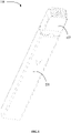
FIG. 2 shows a schematic perspective view of an atomizing assembly shown inFIG. 1 in accordance with a preferred embodiment of the present invention. -
FIG. 3 shows a schematic cross sectional view of the atomizing assembly shown inFIG. 2 in accordance with a preferred embodiment of the present invention. -
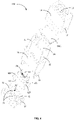
FIG. 4 shows a schematic exploded perspective view of the atomizing assembly shown inFIG. 2 . -
FIG. 5 shows a schematic exploded perspective view of the atomizing assembly shown inFIG. 4 viewed from another view angle by omitting a nozzle shell and a seal. -
FIG. 6 shows a schematic exploded perspective view of an atomizing core ofFIG. 4 showing installation thereof. -
FIG. 7 shows a schematic cross sectional view of the atomizing core shown inFIG. 6 . - In order to facilitate best understanding of the present invention, the present invention will be illustrated in more detail below in conjunction with the attached drawings and preferred embodiments. It should be noted that when an element is expressed as "being fixed to/being fixedly connected to" another element, this element may be directly on the another element, or there may be one or more intervening elements between this element and the another element. When an element is expressed as "being connected to" another element, this element can be directly connected to the another element, or there may be one or more intervening elements between this element and the another element. Terminology used in the specification such as "vertical", "horizontal", "left", "right", "inside", "outside", or similar expressions, etc., is only used for descriptive purposes.
- Unless otherwise defined, any technical and scientific terminology used in this specification has the same meaning as commonly understood by those skilled in the technical field of the present invention. Terminology used in this specification of the present invention is only for a purpose of describing specific embodiments, and is not used to limit the present invention. Terminology such as "and/or" used in this specification includes any and all combinations of one or more related listed items.
- In addition, technical features involved in different embodiments of the present invention described below can be mutually combined as long as they do not conflict with one another.
- In this specification, the term of "installation" means to include methods, such as welding, screwing, clamping, bonding, etc., in order to fix or restrict a certain element or device to a specific position or place. The element or device can be held still in a specific position or place, or can be restricted to move within a limited range. The element or device can be disassembled or cannot be disassembled after being fixed or restricted to a specific position or place. The above is not limited in embodiments of the present application.
- Referring to
FIG. 1 , anelectronic cigarette 300 in accordance with a preferred embodiment of the present invention is provided. Theelectronic cigarette 300 includes abattery assembly 200 and anatomizing assembly 100. Thebattery assembly 200 is installed at an end of theatomizing assembly 100 in order to shape theelectronic cigarette 300 as a straight-lined structure. Alternatively, thebattery assembly 200 and theatomizing assembly 100 are fixedly installed together via engaging connection and/or screw fixing connection. - Understandably, the
battery assembly 200 is electrically connected with theatomizing assembly 100. Thebattery assembly 200 is used to supply power to theatomizing assembly 100 so that theatomizing assembly 100 is able to atomize liquid tobacco into aerosols for users to inhale. - Referring to
FIGS. 2-3 , theatomizing assembly 100 includes anozzle shell 10, abase 20 and a connectingseat 30. Thenozzle shell 10, thebase 20 and the connectingseat 30 are fixedly connected in sequence to form a straight-lined structure. Thenozzle shell 10, thebase 20 and the connectingseat 30 are all disposed along a longitudinal direction a of theatomizing assembly 100. Thebattery assembly 200 is installed at an end of the connectingseat 30 spaced away from thebase 20. - The
nozzle shell 10 is shaped as a cover. Thebase 20 is substantially shaped as a hexahedron. Thenozzle shell 10 covers around outside an end of thebase 20. A throughhole 11 is disposed to penetrate through a top of thenozzle shell 10. Anairflow channel 21 is disposed inside the base 20 or at a lateral side of thebase 20. When thenozzle shell 10 covers around outside the end of thebase 20, the throughhole 11 is spatially communicated with theairflow channel 21. Alternatively, theairflow channel 21 is straightly disposed along a lateral wall of thebase 20. Theairflow channel 21 extends along a direction parallel to the longitudinal direction a of theatomizing assembly 100. - In a preferred embodiment of the present invention, a
protrusion 22 is disposed to protrude at a lateral side of thebase 20. An engagingnotch 12 is disposed at a lateral side of thenozzle shell 10 corresponding to theprotrusion 22. When thenozzle shell 10 covers around on a top of thebase 20, theprotrusion 22 is engaged and mated with the engagingnotch 12 in order to fixedly install thenozzle shell 10 onto the end of thebase 20, and to therefore spatially communicate the throughhole 11 with theairflow channel 21. - A liquid storing
cavity 24 is disposed inside thebase 20. Aliquid filling hole 241 is disposed to be opened at the top of thebase 20 and is spatially communicated with the liquid storingcavity 24. Alternatively, theliquid filling hole 241 is located in a position corresponding to the throughhole 11. Understandably, theatomizing assembly 100 further includes aseal 2411. Theseal 2411 is used to seal and block theliquid filling hole 241. When thenozzle shell 10 is opened and removed by a user, theseal 2411 can be seen by the user. After theseal 2411 is opened and removed by the user, liquid tobacco can be filled into the liquid storingcavity 24 via theliquid filling hole 241. - A
liquid outlet 242 is disposed to be opened at a bottom of thebase 20 and to be spatially communicated with the liquid storingcavity 24. Theliquid outlet 242 is used to conduct liquid tobacco in the liquid storingcavity 24 out of the liquid storingcavity 24. Theliquid outlet 242 and theliquid filling hole 241 are respectively located on two opposite lateral walls of the liquid storingcavity 24. - Referring to
FIGS. 4-6 , the connectingseat 30 is installed at the bottom of thebase 20. Alternatively, the connectingseat 30 and the base 20 are connected to each other via an engaging fixing connection. A lateral wall of thebase 20 and a lateral wall of the connectingseat 30 are engaged and fixedly connected with each other. An accommodating space 40 (As shown inFIG. 3 ) is surrounded between the base 20 and the connectingseat 30. In a preferred embodiment of the present invention, a hook or a plurality ofhooks 23 is formed to extend from a side of a lateral wall of the base 20 facing toward the connectingseat 30. A groove or a plurality ofgroove 33 is disposed to be opened at a lateral wall of the connectingseat 30 corresponding to the hook or the plurality ofhooks 23. The hook or the plurality ofhooks 23 and the groove or the plurality ofgroove 33 are one-to-one corresponded to and mated with each other. The hook or the plurality ofhooks 23 is inserted into the groove or the plurality ofgroove 33 correspondingly to be secured and fixed therein. - The
atomizing assembly 100 further includes anatomizing core 50, anend cover 61 and asupporter 62. Theatomizing core 50 is accommodated in theaccommodating space 40. Theatomizing core 50 includes abody 51. Thebody 51 is installed on thesupporter 62. Theend cover 61 is disposed around thebody 51 and is fixedly connected with thesupporter 62 in order to seal and fix thebody 51. In some embodiments of the present invention, a connection between theend cover 61 and thesupporter 62 can be an integrally formed connection, a fixedly engaging connection, or a screw fixing connection, etc. - In a preferred embodiment of the present invention, a
first installing trough 25 is disposed at a side of the bottom of the base 20 facing toward the connectingseat 30. Asecond installing trough 34 is disposed at a side of the connectingseat 30 facing toward thebase 20. Thefirst installing trough 25 and the second installing trough are correspondingly disposed to match with each other in order to fixedly install theatomizing core 50 therebetween. In particular, a top of theend cover 61 is shaped similarly to thefirst installing trough 25, and the top of theend cover 61 is sealed and installed in thefirst installing trough 25. A bottom of thesupporter 62 is shaped similarly to thesecond installing trough 34, and the bottom of thesupporter 62 is installed in thesecond installing trough 34. When thebase 20 and the connectingseat 30 are engaged and fixed together, theatomizing core 50 is fixedly engaged therebetween. - The
liquid outlet 242 is opened and disposed at a bottom of thefirst installing trough 25. A communicatinghole 611 penetrating through theend cover 61 is opened and disposed at an end of theend cover 61 neighboring theliquid outlet 242, and the communicatinghole 611 is spatially communicated with theliquid outlet 242. In a preferred embodiment of the present invention, the communicatinghole 611 is opened and disposed at the top of theend cover 61. Liquid tobacco in the liquid storingcavity 24 can flow in sequence through theliquid outlet 242 and the communicatinghole 611 to enter thebody 51. - Referring to
FIGS. 6-7 , anatomizing channel 513 is opened and disposed to penetrate through thebody 51. Theatomizing channel 513 extends horizontally. Alternatively, theatomizing channel 513 is shaped as a straight line. Furthermore, theatomizing channel 513 is shaped as a cylinder. Theatomizing core 50 further includes aheater 52 disposed in theatomizing channel 513. For example, theheater 52 is disposed on an inner wall of theatomizing channel 513. In some embodiments of the present invention, theheater 52 is coiled around on the inner wall of theatomizing channel 513, is embedded in the inner wall of theatomizing channel 513, or is partially embedded in the inner wall of theatomizing channel 513 and partially exposed out in theatomizing channel 513. Understandably, theheater 52 is an electrically powered heating body. In a condition of electrification, theheater 52 is heated to raise its temperature. For example, theheater 52 is an electric heating wire. - In a preferred embodiment of the present invention, the
body 51 is made from a porous material having a micro-pore structure. For example, thebody 51 is made from micro-pore ceramic, micro-pore glass or expanded foam materials, etc. Liquid tobacco is conducted to theatomizing channel 513 through porous material via capillary effect. Under heating of theheater 52 to raise its temperature, the liquid tobacco is atomized as aerosols to enter theatomizing channel 513. - An outer sidewall of the
body 51 includes at least an absorbingface 511. In a preferred embodiment of the present invention, the absorbingface 511 is a flat face. The absorbingface 511 is disposed corresponding to the liquid storingcavity 24, and faces toward the communicatinghole 611. A liquid conducting hole or a plurality of liquid conductingholes 512 is opened and disposed on the absorbingface 511, and extends into a wall of thebody 51 from the absorbingface 511. A bottom of the liquid conducting hole or the plurality of liquid conductingholes 512 is located inside the wall of thebody 51. For instance, a plurality of liquid conductingholes 512 is provided and disposed, and is evenly spaced and distributed on the absorbingface 511. Furthermore, shortest conducting distances between bottoms of the plurality of liquid conductingholes 512 and theatomizing channel 513 are respectively set to be equal or substantially equal to one another. The plurality of liquid conductingholes 512 is used to conduct liquid tobacco in the liquid storingcavity 24 into thebody 51. In a preferred embodiment of the present invention, when thebody 51 is transversely disposed, an extension direction of theatomizing channel 513 is perpendicular to the longitudinal direction a of theatomizing assembly 100. In other words, the absorbingface 511 opened and disposed with the liquid conducting hole or the plurality of liquid conductingholes 512 has a large area, i.e., a contact area for the liquid tobacco to enter theatomizing core 50 is large. Conducted liquid tobacco is facilitated to be controlled by the above mentioned structure. - In a preferred embodiment of the present invention, liquid tobacco in the liquid storing
cavity 24 flows in sequence through theliquid outlet 242, the communicatinghole 611 and the liquid conducting hole or a plurality of liquid conductingholes 512 to enter thebody 51. Under heating of theheater 52 to raise its temperature, the liquid tobacco is heated and atomized into aerosols to enter theatomizing channel 513. - In a preferred embodiment of the present invention, the
body 51 is made from porous materials having a preset porosity. Porosity of a porous material is decided by pore diameters of micro pores inside the porous material and a distribution density of the micro pores. When the porosity of the porous material is designed to be smaller, performance of thebody 51 to prevent liquid tobacco from leaking can therefore be enhanced. However, smaller porosity will lower a conducting velocity of liquid tobacco at the same time. Hence, in physical products, a porous material with a proper porosity is required to be selected. For liquid tobacco with a higher viscosity, the liquid conducting hole or the plurality of liquid conductingholes 512 is opened and disposed on thebody 51, and a hole diameter of the liquid conducting hole or the plurality of liquid conductingholes 512 is set to be larger than an average pore diameter of micro pores inside a material of thebody 51. As a result, the conducting velocity of the liquid tobacco can be raised, and the performance of thebody 51 enough to prevent the liquid tobacco from leaking can also be ensured to be enhanced. As a practical solution, the average pore diameter of the micro pores inside the material of thebody 51 is 10 µm ~ 100 µm, for example, preferably is 80 µm. The hole diameter of the liquid conducting hole or the plurality of liquid conductingholes 512 is 10 µm ~ 500 µm, for example, preferably is 100 µm. When the hole diameter of the liquid conducting hole or the plurality of liquid conductingholes 512 is larger than the average pore diameter of the micro pores inside thebody 51, and a viscosity of liquid tobacco is higher, the liquid tobacco can enter the liquid conducting hole or the plurality of liquid conductingholes 512 having a larger hole diameter in order to have the liquid tobacco being conducted smoothly. After the liquid tobacco is heated to raise its temperature, the viscosity of the liquid tobacco is reduced. At this moment, the liquid tobacco enters the micro pores inside the body 51having a smaller pore diameter. Hence, an amount of conducted liquid tobacco can be effectively controlled. The liquid tobacco is finally atomized by theheater 52 into aerosols to enter theatomizing channel 513. Thebody 51 of a preferred embodiment of the present invention is designed to have a better performance to conduct liquid tobacco into the body 41. Particularly, for tobacco liquid with a higher viscosity, thebody 51 of the present invention has a better liquid conductive effect. Meanwhile, thebody 51 of the present invention can achieve a better control on conducting liquid tobacco so as to avoid technical problem of having an excessively large amount of conducted liquid tobacco during a process of heating and atomizing. - A fixing
trough 621 is opened and disposed at a top of thesupporter 62. Thebody 51 is transversely installed in the fixingtrough 621. In other words, thebody 51 is transversely installed in the fixingtrough 621 and a channel extension direction of theatomizing channel 513 is perpendicular to the longitudinal direction a of theatomizing assembly 100. Afirst opening 6211 is disposed at an end of the fixingtrough 621, and asecond opening 6212 is disposed at another end of the fixingtrough 621. Thefirst opening 6211 is disposed corresponding to an end opening of theatomizing channel 513. Thesecond opening 6212 is disposed corresponding to another end opening of theatomizing channel 513. Thesupporter 62 includes an extendingwall 622 formed by extending outwards from an end of thesupporter 62 having thefirst opening 6211. When the bottom of thesupporter 62 is installed in thesecond installing trough 34, the extendingwall 622 is engaged at a lateral wall of thesecond installing trough 34. Besides, a connective trough 6221 (Shown inFIG. 3 ) is formed and surrounded by the extendingwall 622 and thebase 20. Two ends of theconnective trough 6221 are respectively spatially communicated with theairflow channel 21 and thefirst opening 6211. In other words, theairflow channel 21, theconnective trough 6221, thefirst opening 6211, theatomizing channel 513 and thesecond opening 6212 are spatially communicated with one another in sequence. - Referring to
FIGS. 5-6 , afirst airflow trough 623 is formed by extending outwards from an end of thesupporter 62 having thesecond opening 6212. Thefirst airflow trough 623 is spatially communicated with thesecond opening 6212. Asecond airflow trough 32 is disposed in the connectingseat 30. Thesecond airflow trough 32 is spatially communicated with thefirst airflow trough 623. Alternatively, thesecond airflow trough 32 penetrates through the connectingseat 30. Thesecond airflow trough 32 is shaped as a straight line, and an extending direction of thesecond airflow trough 32 is parallel to the longitudinal direction a of theatomizing assembly 100. In a preferred embodiment of the present invention, thesecond airflow trough 32 and thefirst airflow trough 623 are located at a same side of theatomizing assembly 100. The throughhole 11, theairflow channel 21, theconnective trough 6221, thefirst opening 6211, theatomizing channel 513, thesecond opening 6212, thefirst airflow trough 623 and thesecond airflow trough 32 are spatially communicated with one another in sequence. Aerosols formed and existing in theatomizing channel 513 can therefore be inhaled by users via the throughhole 11. - Understandably,
electrodes 31 are disposed at the connectingseat 30. Thebattery assembly 200 is located at an end of the connectingseat 30 spaced away from thebase 20. When the connectingseat 30 is fixedly connected with thebase 20, thebattery assembly 200 is electrically connected with theheater 52 via theelectrodes 31 in order to supply power to theatomizing assembly 100 so that theatomizing assembly 100 is able to atomize liquid tobacco. In a preferred embodiment of the present invention, twoelectrodes 31 are disposed at the connectingseat 30. An end of each of theelectrodes 31 is electrically connected with theheater 52, and another end of the each of theelectrodes 31 is electrically connected with thebattery assembly 200. - To sum up, a technical solution of the present invention includes, but is not limited to include, the following advantages.
- In the
atomizing assembly 100 in accordance with a preferred embodiment of the present invention, a liquid conducting hole or a plurality of liquid conductingholes 512 is opened and disposed on the absorbingface 511 of thebody 51. In actual products, liquid conductingholes 512 with various forms can be disposed and opened on a lateral wall of thebody 51 based on user's requirement in order to much conveniently control a liquid conducting process of liquid tobacco. When thebody 51 is transversely disposed, an extension direction of theatomizing channel 513 is perpendicular to the longitudinal direction a of theatomizing assembly 100. Liquid tobacco enters theatomizing core 50 through the absorbingface 511. A contact area between the liquid tobacco and the absorbing face is large to facilitate control of an amount of conducted liquid tobacco. - Finally, it should be noted that the above embodiments are only used to illustrate technical solutions of the present invention, but not to limit them. Under inventive ideas of the present invention, technical features of the above embodiments or different embodiments can also be combined. Steps can be implemented in any order, and there are many other variations in different aspects of the present invention as described above. For the sake of brevity, those variations are not provided in details. Although the present invention has been described in detail with reference to the foregoing embodiments, it should be understood by the ordinary skilled in the art that they can still modify technical solutions recorded in the foregoing embodiments, or equivalently replace some of the technical features. Besides, these modifications or substitutions do not make essence of corresponding technical solutions deviate from the scope of the technical solutions provided in all preferred embodiments of the present invention.
Claims (13)
- An atomizing assembly applicable to electronic cigarettes comprising a base and an atomizing core; whereina liquid storing cavity is disposed inside the base to store liquid tobacco;the atomizing core is installed in the base, the atomizing core comprises a body and a heater, an atomizing channel is opened and disposed to penetrate through the body, the heater is disposed on an inner wall of the atomizing channel;the body is made from porous materials, an outer sidewall of the body comprises at least an absorbing face, a liquid conducting hole or a plurality of liquid conducting holes is opened and disposed on the absorbing face and extends into a wall of the body from the absorbing face, a bottom of the liquid conducting hole or the plurality of liquid conducting holes is located inside the wall of the body, the liquid tobacco stored in the liquid storing cavity flows into the body via the absorbing face.
- The atomizing assembly as claimed in claim 1, wherein the base is disposed along a longitudinal direction of the atomizing assembly, an extension direction of the atomizing channel is perpendicular to the longitudinal direction of the atomizing assembly.
- The atomizing assembly as claimed in claim 1, wherein an airflow channel is further disposed inside the base, the airflow channel is spatially communicated with the atomizing channel.
- The atomizing assembly as claimed in claim 3, wherein the atomizing assembly further comprises a nozzle shell, a through hole is disposed to penetrate through the nozzle shell, the nozzle shell is installed to the base, the through hole is spatially communicate with the atomizing channel via the airflow channel.
- The atomizing assembly as claimed in claim 1, wherein shortest conducting distances between respective bottoms of the plurality of liquid conducting holes and the inner wall of the atomizing channel are set to be equal to one another.
- The atomizing assembly as claimed in claim 1, wherein a hole diameter of each of the liquid conducting hole or the plurality of liquid conducting holes is set to be larger than an average pore diameter of micro pores inside the body.
- The atomizing assembly as claimed in claim 1, wherein the absorbing face is disposed corresponding to the liquid storing cavity, the absorbing face is a flat face, the liquid conducting hole or the plurality of liquid conducting holes is a plurality of liquid conducting holes, and the plurality of liquid conducting holes is evenly spaced and distributed on the absorbing face.
- The atomizing assembly as claimed in any one of claims 1-7, wherein the base further comprises a liquid filling hole and a liquid outlet;
the liquid filling hole is spatially communicated with the liquid storing cavity, the liquid filling hole and the liquid outlet are respectively located on two opposite lateral walls of the liquid storing cavity, the liquid outlet is spatially communicated with the liquid conducting hole or the plurality of liquid conducting holes. - The atomizing assembly as claimed in claim 8, wherein the atomizing assembly further comprises a supporter and an end cover;the supporter is located at a side of the base, a fixing trough is opened and disposed at a side of the supporter facing toward the base, a part of the body is received in the fixing trough;the end cover is disposed between the base and the supporter, another part of the body is covered around by the end cover, and the end cover is fixed connected with the supporter, the end cover is engaged with the base, and a communicating hole penetrating through the end cover is opened and disposed at the end cover, the liquid outlet is spatially communicated with the liquid conducting hole or the plurality of liquid conducting holes via the communicating hole.
- The atomizing assembly as claimed in claim 9, wherein a first installing trough is disposed at a side of the base facing toward the supporter, the liquid outlet is opened and disposed at a bottom of the first installing trough, the end cover is installed in the first installing trough, and the communicating hole is spatially communicated with the liquid outlet.
- The atomizing assembly as claimed in claim 10, wherein the atomizing assembly further comprises a connecting seat, the connecting seat is installed to the base, a lateral wall of the connecting seat and a lateral wall of the base are fixedly connected with each other, and an accommodating space is formed and surrounded between the connecting seat and the base, the atomizing core is accommodated in the accommodating space.
- The atomizing assembly as claimed in claim 11, wherein a second installing trough is disposed at a side of the connecting seat facing toward the base, the supporter is installed in the second installing trough, when the connecting seat is installed to the base, the first installing trough and the second installing trough are correspondingly disposed to match with each other in order to fixedly install the atomizing core therebetween.
- An electronic cigarette, comprising:an atomizing assembly as claimed in any one of claims 1-12;a battery assembly is installed with the atomizing assembly and is electrically connected with the atomizing assembly.
Applications Claiming Priority (2)
| Application Number | Priority Date | Filing Date | Title |
|---|---|---|---|
| CN201910548306.3A CN110250578A (en) | 2019-06-24 | 2019-06-24 | Atomizing component and electronic cigarette |
| PCT/CN2020/097758 WO2020259505A1 (en) | 2019-06-24 | 2020-06-23 | Atomization assembly, and electronic cigarette |
Publications (3)
| Publication Number | Publication Date |
|---|---|
| EP3987958A1 true EP3987958A1 (en) | 2022-04-27 |
| EP3987958A4 EP3987958A4 (en) | 2022-12-14 |
| EP3987958B1 EP3987958B1 (en) | 2023-12-06 |
Family
ID=67920850
Family Applications (1)
| Application Number | Title | Priority Date | Filing Date |
|---|---|---|---|
| EP20831642.2A Active EP3987958B1 (en) | 2019-06-24 | 2020-06-23 | Atomization assembly, and electronic cigarette |
Country Status (4)
| Country | Link |
|---|---|
| US (1) | US12402663B2 (en) |
| EP (1) | EP3987958B1 (en) |
| CN (1) | CN110250578A (en) |
| WO (1) | WO2020259505A1 (en) |
Families Citing this family (15)
| Publication number | Priority date | Publication date | Assignee | Title |
|---|---|---|---|---|
| CN110250578A (en) | 2019-06-24 | 2019-09-20 | 深圳市合元科技有限公司 | Atomizing component and electronic cigarette |
| CN111165883B (en) * | 2019-12-31 | 2025-08-12 | 深圳市斯科尔科技股份有限公司 | Atomizing device of electronic cigarette and electronic cigarette |
| CN111165882B (en) * | 2019-12-31 | 2024-12-13 | 深圳市斯科尔科技股份有限公司 | Atomization device of electronic cigarette and electronic cigarette |
| WO2021163950A1 (en) * | 2020-02-20 | 2021-08-26 | 深圳麦克韦尔科技有限公司 | Heating assembly, atomizer, and electronic cigarette |
| EP4205578B1 (en) | 2020-08-31 | 2024-10-16 | Shenzhen Smoore Technology Limited | Atomization assembly and electronic atomization device |
| CN112021672B (en) * | 2020-08-31 | 2025-03-14 | 深圳麦克韦尔科技有限公司 | An electronic atomization component and device thereof |
| WO2022041242A1 (en) | 2020-08-31 | 2022-03-03 | 深圳麦克韦尔科技有限公司 | Electronic atomizing assembly and device thereof |
| WO2022141566A1 (en) * | 2020-12-31 | 2022-07-07 | 深圳麦克韦尔科技有限公司 | Electronic atomization device, and atomizer, atomization assembly and atomization core thereof |
| CN113197360B (en) * | 2021-04-30 | 2024-12-06 | 深圳市华诚达精密工业有限公司 | High-strength atomization units, components and devices |
| CN215736904U (en) * | 2021-06-24 | 2022-02-08 | 深圳市艾溹技术研究有限公司 | Electronic atomizer |
| CN113475781B (en) * | 2021-08-10 | 2024-09-03 | 深圳市优维尔科技有限公司 | Atomizer and electronic atomization device |
| CN115707403B (en) * | 2021-08-19 | 2025-03-07 | 比亚迪精密制造有限公司 | Electronic cigarette and its cartridge structure |
| CN116019266A (en) * | 2021-10-26 | 2023-04-28 | 深圳麦克韦尔科技有限公司 | Electronic atomization device, atomizer and atomization core thereof |
| WO2023070322A1 (en) * | 2021-10-26 | 2023-05-04 | 深圳麦克韦尔科技有限公司 | Electronic atomization device, and atomizer and atomization core thereof |
| WO2025145765A1 (en) * | 2024-01-05 | 2025-07-10 | 深圳易佳特科技有限公司 | Heating piece, atomization core, atomizer and electronic cigarette |
Family Cites Families (18)
| Publication number | Priority date | Publication date | Assignee | Title |
|---|---|---|---|---|
| CN204317492U (en) | 2014-11-14 | 2015-05-13 | 深圳市合元科技有限公司 | Be applicable to atomising device and the electronic cigarette of fluid matrix |
| CN205456070U (en) | 2016-02-26 | 2016-08-17 | 深圳市合元科技有限公司 | Liquid atomizer can be annotated and electron cigarette of this atomizer is used |
| CN105747278A (en) * | 2016-04-21 | 2016-07-13 | 深圳市合元科技有限公司 | Cigarette liquid heating device, atomizing unit, atomizer and electronic cigarette |
| CN106136331A (en) * | 2016-08-09 | 2016-11-23 | 卓尔悦欧洲控股有限公司 | A kind of nebulizer and electronic cigarette thereof |
| EP3469928A4 (en) * | 2016-08-18 | 2020-01-15 | China Tobacco Hunan Industrial Co., Ltd. | ATOMIZER AND ELECTRONIC CIGARETTE COMPRISING THE SAME |
| US11006670B2 (en) | 2017-01-16 | 2021-05-18 | Shenzhen First Union Technology Co., Ltd. | Atomizer for electronic cigarette |
| CN109068744B (en) * | 2017-04-14 | 2021-07-02 | 常州市派腾电子技术服务有限公司 | Atomizers and Electronic Cigarettes |
| KR20190051787A (en) * | 2017-11-06 | 2019-05-15 | 주식회사 케이티앤지 | Cartridge and Aerosol Generating Device including the same |
| EP3494811B1 (en) * | 2017-12-07 | 2021-03-17 | Fontem Holdings 1 B.V. | Electronic smoking device with a heating element having a modified surface |
| CN107951079B (en) * | 2017-12-11 | 2020-01-17 | 深圳麦克韦尔科技有限公司 | Electronic cigarette and atomizer thereof |
| CN207707306U (en) * | 2017-12-21 | 2018-08-10 | 上海新型烟草制品研究院有限公司 | A kind of atomizer and electronic cigarette |
| CN208510082U (en) * | 2018-06-27 | 2019-02-19 | 深圳市新宜康科技股份有限公司 | Atomizer device with preheating system for precise control of oil intake |
| WO2019157647A1 (en) * | 2018-02-13 | 2019-08-22 | 深圳麦克韦尔股份有限公司 | Electronic cigarette and heating assembly and heating member thereof |
| CN208096012U (en) * | 2018-03-21 | 2018-11-16 | 深圳市卓力能电子有限公司 | A kind of porous ceramics heating coil atomizer |
| CN208550022U (en) * | 2018-05-31 | 2019-03-01 | 常州市派腾电子技术服务有限公司 | Atomizer and electronic cigarette |
| CN118985981A (en) | 2018-11-15 | 2024-11-22 | 深圳市合元科技有限公司 | Porous heating element, atomizer comprising porous heating element and preparation method of porous heating element |
| CN110250578A (en) | 2019-06-24 | 2019-09-20 | 深圳市合元科技有限公司 | Atomizing component and electronic cigarette |
| CN210471007U (en) * | 2019-06-24 | 2020-05-08 | 深圳市合元科技有限公司 | Atomizing components and electronic cigarettes |
-
2019
- 2019-06-24 CN CN201910548306.3A patent/CN110250578A/en active Pending
-
2020
- 2020-06-23 US US17/623,242 patent/US12402663B2/en active Active
- 2020-06-23 WO PCT/CN2020/097758 patent/WO2020259505A1/en not_active Ceased
- 2020-06-23 EP EP20831642.2A patent/EP3987958B1/en active Active
Also Published As
| Publication number | Publication date |
|---|---|
| WO2020259505A1 (en) | 2020-12-30 |
| EP3987958A4 (en) | 2022-12-14 |
| CN110250578A (en) | 2019-09-20 |
| US20220361578A1 (en) | 2022-11-17 |
| EP3987958B1 (en) | 2023-12-06 |
| US12402663B2 (en) | 2025-09-02 |
Similar Documents
| Publication | Publication Date | Title |
|---|---|---|
| EP3987958B1 (en) | Atomization assembly, and electronic cigarette | |
| US12022861B2 (en) | Electronic cigarette and atomizer thereof with heating assembly | |
| US12042601B2 (en) | Electronic atomization device and atomization assembly | |
| WO2022179300A9 (en) | Heating assembly, atomizer and electronic atomization device | |
| CN210329335U (en) | Atomizer and its electronic cigarette | |
| CN115191652B (en) | Heating components, atomizers and electronic atomization devices | |
| WO2021014139A1 (en) | Porous element for a vapour provision system | |
| US11856989B2 (en) | Atomizing structural member, atomizing device and aerosol generating device | |
| WO2022237453A1 (en) | Atomizer and electronic atomization device therefor | |
| CN219719763U (en) | Atomizing core, atomizing assembly and electronic atomizing device thereof | |
| CN217038896U (en) | Electronic atomization device | |
| US20230088232A1 (en) | Vaporizer and electronic vaporization device | |
| CN115428991A (en) | Atomizer and electronic atomization device | |
| WO2025175989A1 (en) | Electronic atomization device, atomizer and atomization core | |
| US12588706B2 (en) | Atomizing core, atomizer, electronic cigarette, and assembly method | |
| CN218898354U (en) | Atomizing core and aerosol generating device | |
| CN215936302U (en) | Atomizer | |
| CN116158557B (en) | Atomizer and electronic atomizing device | |
| CN216568378U (en) | Atomizer | |
| CN223979439U (en) | Electronic atomizing devices and atomizers | |
| CN218588220U (en) | Atomizer and electronic atomization device | |
| KR20230098126A (en) | Atomization device with excellent atomization effect | |
| CN116406850A (en) | Heating components, atomizers and electronic atomization devices | |
| CN223094797U (en) | Atomizer and atomizing device | |
| CN220571548U (en) | Atomizer and electronic atomization device |
Legal Events
| Date | Code | Title | Description |
|---|---|---|---|
| STAA | Information on the status of an ep patent application or granted ep patent |
Free format text: STATUS: THE INTERNATIONAL PUBLICATION HAS BEEN MADE |
|
| PUAI | Public reference made under article 153(3) epc to a published international application that has entered the european phase |
Free format text: ORIGINAL CODE: 0009012 |
|
| STAA | Information on the status of an ep patent application or granted ep patent |
Free format text: STATUS: REQUEST FOR EXAMINATION WAS MADE |
|
| 17P | Request for examination filed |
Effective date: 20220113 |
|
| AK | Designated contracting states |
Kind code of ref document: A1 Designated state(s): AL AT BE BG CH CY CZ DE DK EE ES FI FR GB GR HR HU IE IS IT LI LT LU LV MC MK MT NL NO PL PT RO RS SE SI SK SM TR |
|
| RIC1 | Information provided on ipc code assigned before grant |
Ipc: A24F 40/44 20200101ALI20220722BHEP Ipc: A24F 15/015 20200101ALI20220722BHEP Ipc: A24F 47/00 20200101AFI20220722BHEP |
|
| DAV | Request for validation of the european patent (deleted) | ||
| DAX | Request for extension of the european patent (deleted) | ||
| STAA | Information on the status of an ep patent application or granted ep patent |
Free format text: STATUS: EXAMINATION IS IN PROGRESS |
|
| A4 | Supplementary search report drawn up and despatched |
Effective date: 20221116 |
|
| RIC1 | Information provided on ipc code assigned before grant |
Ipc: A24F 40/44 20200101ALI20221110BHEP Ipc: A24F 15/015 20200101ALI20221110BHEP Ipc: A24F 47/00 20200101AFI20221110BHEP |
|
| 17Q | First examination report despatched |
Effective date: 20221128 |
|
| GRAP | Despatch of communication of intention to grant a patent |
Free format text: ORIGINAL CODE: EPIDOSNIGR1 |
|
| STAA | Information on the status of an ep patent application or granted ep patent |
Free format text: STATUS: GRANT OF PATENT IS INTENDED |
|
| INTG | Intention to grant announced |
Effective date: 20230628 |
|
| GRAS | Grant fee paid |
Free format text: ORIGINAL CODE: EPIDOSNIGR3 |
|
| GRAA | (expected) grant |
Free format text: ORIGINAL CODE: 0009210 |
|
| STAA | Information on the status of an ep patent application or granted ep patent |
Free format text: STATUS: THE PATENT HAS BEEN GRANTED |
|
| AK | Designated contracting states |
Kind code of ref document: B1 Designated state(s): AL AT BE BG CH CY CZ DE DK EE ES FI FR GB GR HR HU IE IS IT LI LT LU LV MC MK MT NL NO PL PT RO RS SE SI SK SM TR |
|
| REG | Reference to a national code |
Ref country code: GB Ref legal event code: FG4D |
|
| REG | Reference to a national code |
Ref country code: DE Ref legal event code: R096 Ref document number: 602020022451 Country of ref document: DE |
|
| REG | Reference to a national code |
Ref country code: CH Ref legal event code: EP |
|
| REG | Reference to a national code |
Ref country code: IE Ref legal event code: FG4D |
|
| REG | Reference to a national code |
Ref country code: LT Ref legal event code: MG9D |
|
| PG25 | Lapsed in a contracting state [announced via postgrant information from national office to epo] |
Ref country code: GR Free format text: LAPSE BECAUSE OF FAILURE TO SUBMIT A TRANSLATION OF THE DESCRIPTION OR TO PAY THE FEE WITHIN THE PRESCRIBED TIME-LIMIT Effective date: 20240307 |
|
| REG | Reference to a national code |
Ref country code: NL Ref legal event code: MP Effective date: 20231206 |
|
| PG25 | Lapsed in a contracting state [announced via postgrant information from national office to epo] |
Ref country code: LT Free format text: LAPSE BECAUSE OF FAILURE TO SUBMIT A TRANSLATION OF THE DESCRIPTION OR TO PAY THE FEE WITHIN THE PRESCRIBED TIME-LIMIT Effective date: 20231206 |
|
| PG25 | Lapsed in a contracting state [announced via postgrant information from national office to epo] |
Ref country code: ES Free format text: LAPSE BECAUSE OF FAILURE TO SUBMIT A TRANSLATION OF THE DESCRIPTION OR TO PAY THE FEE WITHIN THE PRESCRIBED TIME-LIMIT Effective date: 20231206 |
|
| PG25 | Lapsed in a contracting state [announced via postgrant information from national office to epo] |
Ref country code: LT Free format text: LAPSE BECAUSE OF FAILURE TO SUBMIT A TRANSLATION OF THE DESCRIPTION OR TO PAY THE FEE WITHIN THE PRESCRIBED TIME-LIMIT Effective date: 20231206 Ref country code: GR Free format text: LAPSE BECAUSE OF FAILURE TO SUBMIT A TRANSLATION OF THE DESCRIPTION OR TO PAY THE FEE WITHIN THE PRESCRIBED TIME-LIMIT Effective date: 20240307 Ref country code: ES Free format text: LAPSE BECAUSE OF FAILURE TO SUBMIT A TRANSLATION OF THE DESCRIPTION OR TO PAY THE FEE WITHIN THE PRESCRIBED TIME-LIMIT Effective date: 20231206 Ref country code: BG Free format text: LAPSE BECAUSE OF FAILURE TO SUBMIT A TRANSLATION OF THE DESCRIPTION OR TO PAY THE FEE WITHIN THE PRESCRIBED TIME-LIMIT Effective date: 20240306 |
|
| REG | Reference to a national code |
Ref country code: AT Ref legal event code: MK05 Ref document number: 1637538 Country of ref document: AT Kind code of ref document: T Effective date: 20231206 |
|
| PG25 | Lapsed in a contracting state [announced via postgrant information from national office to epo] |
Ref country code: NL Free format text: LAPSE BECAUSE OF FAILURE TO SUBMIT A TRANSLATION OF THE DESCRIPTION OR TO PAY THE FEE WITHIN THE PRESCRIBED TIME-LIMIT Effective date: 20231206 |
|
| PG25 | Lapsed in a contracting state [announced via postgrant information from national office to epo] |
Ref country code: SE Free format text: LAPSE BECAUSE OF FAILURE TO SUBMIT A TRANSLATION OF THE DESCRIPTION OR TO PAY THE FEE WITHIN THE PRESCRIBED TIME-LIMIT Effective date: 20231206 Ref country code: RS Free format text: LAPSE BECAUSE OF FAILURE TO SUBMIT A TRANSLATION OF THE DESCRIPTION OR TO PAY THE FEE WITHIN THE PRESCRIBED TIME-LIMIT Effective date: 20231206 Ref country code: NO Free format text: LAPSE BECAUSE OF FAILURE TO SUBMIT A TRANSLATION OF THE DESCRIPTION OR TO PAY THE FEE WITHIN THE PRESCRIBED TIME-LIMIT Effective date: 20240306 Ref country code: NL Free format text: LAPSE BECAUSE OF FAILURE TO SUBMIT A TRANSLATION OF THE DESCRIPTION OR TO PAY THE FEE WITHIN THE PRESCRIBED TIME-LIMIT Effective date: 20231206 Ref country code: LV Free format text: LAPSE BECAUSE OF FAILURE TO SUBMIT A TRANSLATION OF THE DESCRIPTION OR TO PAY THE FEE WITHIN THE PRESCRIBED TIME-LIMIT Effective date: 20231206 Ref country code: HR Free format text: LAPSE BECAUSE OF FAILURE TO SUBMIT A TRANSLATION OF THE DESCRIPTION OR TO PAY THE FEE WITHIN THE PRESCRIBED TIME-LIMIT Effective date: 20231206 |
|
| PG25 | Lapsed in a contracting state [announced via postgrant information from national office to epo] |
Ref country code: IS Free format text: LAPSE BECAUSE OF FAILURE TO SUBMIT A TRANSLATION OF THE DESCRIPTION OR TO PAY THE FEE WITHIN THE PRESCRIBED TIME-LIMIT Effective date: 20240406 |
|
| PG25 | Lapsed in a contracting state [announced via postgrant information from national office to epo] |
Ref country code: CZ Free format text: LAPSE BECAUSE OF FAILURE TO SUBMIT A TRANSLATION OF THE DESCRIPTION OR TO PAY THE FEE WITHIN THE PRESCRIBED TIME-LIMIT Effective date: 20231206 Ref country code: AT Free format text: LAPSE BECAUSE OF FAILURE TO SUBMIT A TRANSLATION OF THE DESCRIPTION OR TO PAY THE FEE WITHIN THE PRESCRIBED TIME-LIMIT Effective date: 20231206 |
|
| PG25 | Lapsed in a contracting state [announced via postgrant information from national office to epo] |
Ref country code: SK Free format text: LAPSE BECAUSE OF FAILURE TO SUBMIT A TRANSLATION OF THE DESCRIPTION OR TO PAY THE FEE WITHIN THE PRESCRIBED TIME-LIMIT Effective date: 20231206 |
|
| PG25 | Lapsed in a contracting state [announced via postgrant information from national office to epo] |
Ref country code: SM Free format text: LAPSE BECAUSE OF FAILURE TO SUBMIT A TRANSLATION OF THE DESCRIPTION OR TO PAY THE FEE WITHIN THE PRESCRIBED TIME-LIMIT Effective date: 20231206 Ref country code: SK Free format text: LAPSE BECAUSE OF FAILURE TO SUBMIT A TRANSLATION OF THE DESCRIPTION OR TO PAY THE FEE WITHIN THE PRESCRIBED TIME-LIMIT Effective date: 20231206 Ref country code: RO Free format text: LAPSE BECAUSE OF FAILURE TO SUBMIT A TRANSLATION OF THE DESCRIPTION OR TO PAY THE FEE WITHIN THE PRESCRIBED TIME-LIMIT Effective date: 20231206 Ref country code: IT Free format text: LAPSE BECAUSE OF FAILURE TO SUBMIT A TRANSLATION OF THE DESCRIPTION OR TO PAY THE FEE WITHIN THE PRESCRIBED TIME-LIMIT Effective date: 20231206 Ref country code: IS Free format text: LAPSE BECAUSE OF FAILURE TO SUBMIT A TRANSLATION OF THE DESCRIPTION OR TO PAY THE FEE WITHIN THE PRESCRIBED TIME-LIMIT Effective date: 20240406 Ref country code: EE Free format text: LAPSE BECAUSE OF FAILURE TO SUBMIT A TRANSLATION OF THE DESCRIPTION OR TO PAY THE FEE WITHIN THE PRESCRIBED TIME-LIMIT Effective date: 20231206 Ref country code: CZ Free format text: LAPSE BECAUSE OF FAILURE TO SUBMIT A TRANSLATION OF THE DESCRIPTION OR TO PAY THE FEE WITHIN THE PRESCRIBED TIME-LIMIT Effective date: 20231206 Ref country code: AT Free format text: LAPSE BECAUSE OF FAILURE TO SUBMIT A TRANSLATION OF THE DESCRIPTION OR TO PAY THE FEE WITHIN THE PRESCRIBED TIME-LIMIT Effective date: 20231206 |
|
| PG25 | Lapsed in a contracting state [announced via postgrant information from national office to epo] |
Ref country code: PL Free format text: LAPSE BECAUSE OF FAILURE TO SUBMIT A TRANSLATION OF THE DESCRIPTION OR TO PAY THE FEE WITHIN THE PRESCRIBED TIME-LIMIT Effective date: 20231206 Ref country code: PT Free format text: LAPSE BECAUSE OF FAILURE TO SUBMIT A TRANSLATION OF THE DESCRIPTION OR TO PAY THE FEE WITHIN THE PRESCRIBED TIME-LIMIT Effective date: 20240408 |
|
| PG25 | Lapsed in a contracting state [announced via postgrant information from national office to epo] |
Ref country code: PT Free format text: LAPSE BECAUSE OF FAILURE TO SUBMIT A TRANSLATION OF THE DESCRIPTION OR TO PAY THE FEE WITHIN THE PRESCRIBED TIME-LIMIT Effective date: 20240408 Ref country code: PL Free format text: LAPSE BECAUSE OF FAILURE TO SUBMIT A TRANSLATION OF THE DESCRIPTION OR TO PAY THE FEE WITHIN THE PRESCRIBED TIME-LIMIT Effective date: 20231206 |
|
| REG | Reference to a national code |
Ref country code: DE Ref legal event code: R097 Ref document number: 602020022451 Country of ref document: DE |
|
| PG25 | Lapsed in a contracting state [announced via postgrant information from national office to epo] |
Ref country code: DK Free format text: LAPSE BECAUSE OF FAILURE TO SUBMIT A TRANSLATION OF THE DESCRIPTION OR TO PAY THE FEE WITHIN THE PRESCRIBED TIME-LIMIT Effective date: 20231206 |
|
| PLBE | No opposition filed within time limit |
Free format text: ORIGINAL CODE: 0009261 |
|
| STAA | Information on the status of an ep patent application or granted ep patent |
Free format text: STATUS: NO OPPOSITION FILED WITHIN TIME LIMIT |
|
| PG25 | Lapsed in a contracting state [announced via postgrant information from national office to epo] |
Ref country code: SI Free format text: LAPSE BECAUSE OF FAILURE TO SUBMIT A TRANSLATION OF THE DESCRIPTION OR TO PAY THE FEE WITHIN THE PRESCRIBED TIME-LIMIT Effective date: 20231206 |
|
| PG25 | Lapsed in a contracting state [announced via postgrant information from national office to epo] |
Ref country code: SI Free format text: LAPSE BECAUSE OF FAILURE TO SUBMIT A TRANSLATION OF THE DESCRIPTION OR TO PAY THE FEE WITHIN THE PRESCRIBED TIME-LIMIT Effective date: 20231206 Ref country code: DK Free format text: LAPSE BECAUSE OF FAILURE TO SUBMIT A TRANSLATION OF THE DESCRIPTION OR TO PAY THE FEE WITHIN THE PRESCRIBED TIME-LIMIT Effective date: 20231206 |
|
| 26N | No opposition filed |
Effective date: 20240909 |
|
| PG25 | Lapsed in a contracting state [announced via postgrant information from national office to epo] |
Ref country code: MC Free format text: LAPSE BECAUSE OF FAILURE TO SUBMIT A TRANSLATION OF THE DESCRIPTION OR TO PAY THE FEE WITHIN THE PRESCRIBED TIME-LIMIT Effective date: 20231206 |
|
| REG | Reference to a national code |
Ref country code: CH Ref legal event code: PL |
|
| PG25 | Lapsed in a contracting state [announced via postgrant information from national office to epo] |
Ref country code: LU Free format text: LAPSE BECAUSE OF NON-PAYMENT OF DUE FEES Effective date: 20240623 |
|
| P01 | Opt-out of the competence of the unified patent court (upc) registered |
Free format text: CASE NUMBER: APP_11082/2025 Effective date: 20250306 |
|
| PG25 | Lapsed in a contracting state [announced via postgrant information from national office to epo] |
Ref country code: IE Free format text: LAPSE BECAUSE OF NON-PAYMENT OF DUE FEES Effective date: 20240623 |
|
| PG25 | Lapsed in a contracting state [announced via postgrant information from national office to epo] |
Ref country code: CH Free format text: LAPSE BECAUSE OF NON-PAYMENT OF DUE FEES Effective date: 20240630 Ref country code: BE Free format text: LAPSE BECAUSE OF NON-PAYMENT OF DUE FEES Effective date: 20240630 |
|
| REG | Reference to a national code |
Ref country code: BE Ref legal event code: MM Effective date: 20240630 |
|
| PGFP | Annual fee paid to national office [announced via postgrant information from national office to epo] |
Ref country code: DE Payment date: 20250617 Year of fee payment: 6 |
|
| PGFP | Annual fee paid to national office [announced via postgrant information from national office to epo] |
Ref country code: GB Payment date: 20250625 Year of fee payment: 6 |
|
| PGFP | Annual fee paid to national office [announced via postgrant information from national office to epo] |
Ref country code: FR Payment date: 20250630 Year of fee payment: 6 |
|
| PG25 | Lapsed in a contracting state [announced via postgrant information from national office to epo] |
Ref country code: FI Free format text: LAPSE BECAUSE OF FAILURE TO SUBMIT A TRANSLATION OF THE DESCRIPTION OR TO PAY THE FEE WITHIN THE PRESCRIBED TIME-LIMIT Effective date: 20231207 |
|
| PG25 | Lapsed in a contracting state [announced via postgrant information from national office to epo] |
Ref country code: CY Free format text: LAPSE BECAUSE OF FAILURE TO SUBMIT A TRANSLATION OF THE DESCRIPTION OR TO PAY THE FEE WITHIN THE PRESCRIBED TIME-LIMIT; INVALID AB INITIO Effective date: 20200623 |
|
| PG25 | Lapsed in a contracting state [announced via postgrant information from national office to epo] |
Ref country code: HU Free format text: LAPSE BECAUSE OF FAILURE TO SUBMIT A TRANSLATION OF THE DESCRIPTION OR TO PAY THE FEE WITHIN THE PRESCRIBED TIME-LIMIT; INVALID AB INITIO Effective date: 20200623 |