EP3987944A1 - Hookah closure system - Google Patents
Hookah closure system Download PDFInfo
- Publication number
- EP3987944A1 EP3987944A1 EP20203671.1A EP20203671A EP3987944A1 EP 3987944 A1 EP3987944 A1 EP 3987944A1 EP 20203671 A EP20203671 A EP 20203671A EP 3987944 A1 EP3987944 A1 EP 3987944A1
- Authority
- EP
- European Patent Office
- Prior art keywords
- closure member
- closure
- hookah
- lower closure
- notch
- Prior art date
- Legal status (The legal status is an assumption and is not a legal conclusion. Google has not performed a legal analysis and makes no representation as to the accuracy of the status listed.)
- Withdrawn
Links
- XLYOFNOQVPJJNP-UHFFFAOYSA-N water Substances O XLYOFNOQVPJJNP-UHFFFAOYSA-N 0.000 claims abstract description 19
- 238000007373 indentation Methods 0.000 claims description 16
- 230000000903 blocking effect Effects 0.000 claims description 2
- 230000003213 activating effect Effects 0.000 description 10
- 239000000779 smoke Substances 0.000 description 4
- 230000008901 benefit Effects 0.000 description 3
- 238000000034 method Methods 0.000 description 3
- 238000010926 purge Methods 0.000 description 2
- 230000000391 smoking effect Effects 0.000 description 2
- 241000208125 Nicotiana Species 0.000 description 1
- 235000002637 Nicotiana tabacum Nutrition 0.000 description 1
- 229910000831 Steel Inorganic materials 0.000 description 1
- 239000003245 coal Substances 0.000 description 1
- 238000004891 communication Methods 0.000 description 1
- 230000001419 dependent effect Effects 0.000 description 1
- 239000002360 explosive Substances 0.000 description 1
- 239000012530 fluid Substances 0.000 description 1
- 230000001771 impaired effect Effects 0.000 description 1
- 238000003780 insertion Methods 0.000 description 1
- 230000037431 insertion Effects 0.000 description 1
- 238000004519 manufacturing process Methods 0.000 description 1
- 239000002184 metal Substances 0.000 description 1
- 229920003023 plastic Polymers 0.000 description 1
- 239000004033 plastic Substances 0.000 description 1
- 230000000284 resting effect Effects 0.000 description 1
- 238000007789 sealing Methods 0.000 description 1
- 239000007787 solid Substances 0.000 description 1
- 239000010959 steel Substances 0.000 description 1
- 238000009423 ventilation Methods 0.000 description 1
Images



Classifications
-
- A—HUMAN NECESSITIES
- A24—TOBACCO; CIGARS; CIGARETTES; SIMULATED SMOKING DEVICES; SMOKERS' REQUISITES
- A24F—SMOKERS' REQUISITES; MATCH BOXES; SIMULATED SMOKING DEVICES
- A24F1/00—Tobacco pipes
- A24F1/30—Hookahs
-
- A—HUMAN NECESSITIES
- A24—TOBACCO; CIGARS; CIGARETTES; SIMULATED SMOKING DEVICES; SMOKERS' REQUISITES
- A24F—SMOKERS' REQUISITES; MATCH BOXES; SIMULATED SMOKING DEVICES
- A24F2700/00—Tobacco pipes; Bad-covers or accessories for smokers' pipes
- A24F2700/08—Bowl-covers or accessories for smokers' pipes
Definitions
- the present invention relates to a closure system for a hookah. Further, the present invention relates to a hookah
- Water pipes also Shisha or Hookah, usually comprise a water container or bowl that is sealingly closed by a closure head attached to the water container.
- the closure head is generally designed as a multipart component in order to facilitate assembly and disassembly to and from the water container respectively the smoking equipment to be attached thereto.
- a lower closure member is attached to the water container and an upper closure member to be tightly connected to the lower closure member is designed to be connected to the smoking equipment.
- the upper closure member comprises a center connection for connecting to a smoke pipe, to which upper end a tobacco and coal assembly is attached, extending through the lower closure member into the water container and two further connections for attaching at least one smoke hose and potentially a purge valve.
- closure head In order to ensure a reliable functioning of the hookah it is essential that the closure head completely seals the water container. Leakage between the lower and the upper closure members causes an unsatisfying usage of the hookah. Further, the connections to the smoke pipe, the at least one smoke hose and the purge valve need to be tight as well. It has been found out that known closure systems, such as screw closures, snap-fit closures or a bayonet catch, either have the disadvantage of long assembly respectively disassembly times or tend to be not tight or permanent enough in particular due to unintentional releasing of the closure system.
- a hookah closure system that essentially consists of three parts, namely a lower closure part to be attached to the water base, an upper closure part with the connections for the at least one hookah hose and the hookah stem, and an activating sleeve for securely fixing the lower and upper closure parts together and for releasing the attachment between the lower and upper closure parts.
- the spring biasing causes the catch mechanism to secure the lower and upper closure parts with each other, when activating the activating sleeve, the spring biasing must be overcome, thereby releasing the catch mechanism in order to enable disassembly of the lower and upper closure parts.
- the catch mechanism is realized by several circumferentially spaced through holes in the lower closure part in which locking balls are movably arranged and a circular groove formed on the outside circumference of the upper closure part. The locking balls may be forced into the circular groove by the activating sleeve thereby establishing a form and force fitting attachment of the lower and upper closure parts. By activating the activating sleeve the locking balls are disengaged from the circular groove in order to enable disassembly of the lower and upper closure parts.
- a general idea of the invention relates to providing a hookah closure system with an assembling aid that may be configured such that a wrong assembly of the hookah closure system is prohibited. This may be achieved by providing a predefined mounting direction and mounting orientation of its components. Additionally, by using the assembly aid also for securing respectively releasing the closure system a simple, cost-efficient and easy to handle hookah closure system is achieved.
- a further general idea of the present invention relates to equipping the closure system with a sliding guide means for switching between a closed state of the hookah closure system and a released state of the hookah closure system.
- the sliding guide means provides the user with a predefined and limited actuation movement which is also very intuitive.
- a closure system for a hookah comprises an upper closure member configured to be connected to a hookah hose and/or a hookah stem.
- the upper closure member may comprise three connections for attaching at least one hookah hose and a hookah stem and potentially an adapter cone providing air outlet.
- the connections may be through holes possibly having a threading, snapping or clamping mechanism for easy and secure attachment of the hookah hose respectively hookah stem.
- the closure system further comprises a lower closure member configured to be connected to a water container. The connection between the lower closure member and the water container may be realized by any suitable means.
- an assembling aid having an assembly state in which assembly of the upper and lower closure members with each other is enabled and a blocking state in which assembly of the upper and lower closure members with each other is disabled.
- the assembling aid may for example define a predetermined direction, position and/or orientation of the upper and lower closure members with regard to each other in which assembly is enabled. When the upper and lower closure members do not coincide with the predetermined direction, position and/or orientation assembly of the upper and lower closure members may be disabled.
- the hookah closure system further comprises an actuating member configured to cooperate with the assembling aid in order to secure the upper and lower closure members to each other. Due to the fact that the assembling aid is on the one hand used for easy and correct assembly of the lower and upper closure members and on the other hand for fixing the upper and lower closure members to each other the closure system according to the present invention requires less parts respectively components than known prior art closure systems while at the same time providing advantages with regard to assembly and usability.
- the actuating member may cooperate with the assembling aid such that in an assembled state of the upper and lower closure members with each other disassembly is prohibited. In other words, the closure system is active in particular to ensure safe and reliable functioning of the hookah.
- the actuating member may have a passive state, in which the upper closure member may be disassembled from the lower closure member, and an active state, in which the upper closure member is secured to the lower closure member against disassembly.
- Assembly of the upper closure member with the lower closure member may be realized by insertion of one component into the other.
- the upper and lower closure members may be configured such that the upper closure member may be inserted into the lower closure member in a telescope-manner.
- the assembling aid is realized by a corresponding, particularly form-fitting, protrusion-notch-structure arranged on the upper and lower closure members.
- at least one protrusion preferably several protrusions
- at least one notch preferably several notches
- the number of protrusions may equal the number of notches.
- the upper and lower closure members may be rotationally formed sleeves having a rotational axis.
- An assembly respectively disassembly direction of the upper and lower closure members may be parallel with regard to the rotational axis.
- the protrusion-notch-structure may define at least one predetermined assembly position, preferably two, three or four predetermined assembly positions, direction and/or orientation, depending on the number of protrusions respectively notches provided.
- the protrusion-notch-structure is realized by at least one upper closure member-sided protrusion and/or notch and by at least one lower closure member-sided notch and/or protrusion, which engage with each other upon mounting the upper closure member with the lower closure member.
- the notch may be oriented in the lengthwise direction of the respective closure member.
- the upper closure member-sided protrusion may be arranged on an outer circumference of a preferably cylindrical shaped assembly socket.
- the lower closure member-sided notch may be arranged on an inner circumference of a ring-shaped or sleeve shaped assembly socket corresponding to the assembly socket of the upper closure member.
- the assembling aid defines a guiding assembly path and/or an axial stop defining an axial end assembly position of the upper closure member with regard to the lower closure member. Therefore, false assembly may be prohibited. Additionally, the axial stop facilitates establishing the assembly end position. By the guiding assembly path, the upper closure member may be guided into the assembly end position which is given when abutting, preferably in a translational direction, against the axial stop.
- the upper and lower closure members are configured such that the upper closure member may be inserted into the lower closure member in a telescope-manner.
- the assembling aid comprises at least two protrusions arranged on an outer circumference of the upper closure member and at least two notches, particularly extending in the lengthwise direction of the lower closure member, arranged on an inner circumference of the lower closure member.
- each protrusion may engage with one notch.
- the number of protrusions may equal the number of notches.
- the notches may have the same shape and/or dimension. Further, the protrusions may have the same shape and/or dimension.
- the actuating member when securing the upper and lower closure members to each other, engages the protrusion-notch-structure.
- the actuating member engages the protrusion-notch-structure such that the notch or guiding path is blocked in order to prevent relative movement of the upper and lower closure members. In particular, relative movement in the lengthwise, telescope and/or a rotational direction is prevented.
- the actuating member is a rotational sleeve with an inner locking ring configured to engage the assembling aid, in particular the protrusion-notch-structure.
- the inner locking ring may protrude into the notch or guiding path in order to prevent disassembly of the upper and lower closure members from one another.
- the locking ring comprises at least one indentation allocated to the protrusion-notch-structure such that the indentation may form a continuous groove or path with the notch in order to allow passage of the protrusion and/or such that the indentation is rotationally offset with regard to the notch in order to secure the upper and lower closure members to each other.
- the number of indentations may correspond to the number of protrusions and/or notches of the protrusion-notch-structure. Further, the indentations may have the same cross-section as the notches.
- a closure system for a hookah comprises an upper closure member configured to be connected to a hookah hose and/or a hookah stem.
- the upper closure member may comprise three connections for attaching at least one hookah hose and a hookah stem.
- the connections may be through holes possibly having a threading, snapping or clamping mechanism for easy and secure attachment of the hookah hose respectively hookah stem.
- the closure system further comprises a lower closure member configured to be connected to a water container. The connection between the lower closure member and the water container may be realized by any suitable means.
- the hookah closure system also comprises an actuating member that has a passive state, in which the upper closure member may be disassembled from the lower closure member, and an active state, in which the upper closure member is secured to the lower closure member against disassembly.
- switching between the active and the passive state is performed via a sliding guide means.
- the sliding guide means may provide a defined and guided actuation movement, thereby facilitating the use of the closure system.
- the sliding guide means has a further advantage that it only enables an actuation movement in a predetermined direction and/or for a predetermined extent of movement.
- the sliding guide means may define at least two, preferably exactly two, engagement or locking end positions, one corresponding to the active state, one corresponding to the passive state.
- the actuation movement of the actuating member which may be a rotational sleeve may be a rotational movement.
- Locking the hookah closure system may be done by a clockwise rotation and releasing of the hookah closure system may be done by a counterclockwise rotation, or vice versa.
- the sliding guide means is realized by a slot arranged in the actuating member and a slide block arranged on the lower closure member.
- the slide block shape may be adapted with regard to the slot shape.
- the slide block may be press-fittingly mounted in an opening of the lower closure member. Further, upon actuating the actuating member in order to switch between the active and passive state the slide block is guided within the slot in particular between two engagement or locking end positions, preferably one corresponding to the active state and one corresponding to the passive state.
- the slide block upon actuating the actuating member in order to switch between the active and passive state the slide block is guided within the slot between two end positions corresponding to the active and passive state.
- the actuating member is a rotational sleeve and the slot extends in a circumferential direction with regard to a rotational axis of the rotational sleeve, wherein particularly the circumferential extension of the slot is in the range of 15° to 45°, in particular is 30°. Therefore, a quick and easy assembly and disassembly mechanism is provided.
- the closure system further comprises a catch mechanism defining at least one latching position corresponding to either a passive state of the actuating member, in which the upper closure member may be disassembled from the lower closure member, or an active state, in which the upper closure member is secured to the lower closure member against disassembly.
- the catch mechanism defines two latching positions one of which corresponding to the active state and the other corresponding to the passive state.
- the sliding guide means and the catch mechanism are adapted with regard to each other.
- movement via the sliding guide means is adapted with regard to the at least one latching position.
- the sliding guide means and the catch mechanism are adapted with regard to each other such that each end position of the sliding guide means is allocated to a latching position of the catch mechanism.
- the catch mechanism cooperates with a biasing means providing a resistibility against actuation of the actuating member.
- the biasing means may comprise a spring, such as a pressure spring.
- the catch mechanism may comprise at least one, preferably two, depression formed in the lower closure member and a movable member, such as a ball, preferably adapted in shame with regard to the depression, which engages the at least one depression when engaging the corresponding and position of the actuation member.
- a movable member such as a ball
- the catch mechanism simultaneously engages, in particular the movable member engages the depression.
- the biasing means further comprises a force transmitter, preferably a rotational sleeve, acting on the spring in order to the press the spring for pre-tensioning the movable member into a latching position, preferably into the depression.
- the force transmitter may be arranged inbetween the upper and lower closure members.
- the force transmitter may also function as a cover for the lower closure member.
- a hookah is provided.
- the hookah according to the invention comprises a closure system configured according to one of the preceding aspects or preferred embodiments.
- a method for operating a hookah closure system is provided. It is noted that the method according to the invention can be defined such that it realizes the hookah closure system according to the described aspects of the invention, and vice versa.
- a hookah closure system is generally indicated with the reference numeral 1.
- the Hookah closure system 1 in an example embodiment is shown in an exploded view.
- the example embodiment of the Hookah closure system 1, Figure 1 comprises an upper closure member, a lower closure member 5, and an actuating member 7 as main components.
- the Hookah closure system 1 further comprises a slide lock 9 in the form of a guiding pin that is part of a sliding guide means 63 for securing and releasing the Hookah closure system 1 which will be explained later on.
- a pressure spring 11 of a biasing means and a locking ball 13 of a catch mechanism is shown.
- the Hookah closure system 1 comprises a force transmitter 15 in the form of a cover arranged in between the lower and upper closure members 5,3. Functioning of the Hookah closure system 1 according to the present invention and preferred embodiments of the single components will be explained under reference to Figures 2-10 .
- the upper closure member 3 is shown in different views.
- the upper closure member 3 is essentially manufactured as a solid piece, in particular made out of metal or plastics and essentially comprises a cylindrical shape.
- the upper closure member 3 comprises a central channel 17 for connecting to a Hookah stem (not shown) and for providing fluid communication between the Hookah stem and a water container to be attached to the lower closure member 5.
- the channel 17 may comprise a thread 19 at least section-wisely provided for attachment of the Hookah stem.
- two further channels 21, 23 are provided for connecting to a Hookah hose and an adapter cone for providing air outlet with regard to the water container.
- the channels 21, 23 may be equipped with a thread 25 for easy attachment of the respective components.
- another thread 27 may be arranged on an opposite end of the channel 17, for example for connecting to a steel pipe (not shown).
- the upper closure member consists of two cylinder sections 29, 31 and an abutment ring or surface 33 protruding the outer diameters of the cylinder sections 29, 31.
- the upper cylinder section 29 essentially serves for connecting to the Hookah equipment, such as the Hookah hose, the Hookah stem and potentially an adapter cone for ventilation.
- the lower cylinder section 31 has the function to form the connection with the lower closure member 5 and is designed such that it may be translationally inserted into a corresponding opening 35 ( Figure 7, 8 ) of the lower closure member 5.
- the assembling aid 37 not only serves to facilitate assembly and disassembly, in particular to prohibit false assembly, but also for locking the Hookah closure system 1. Locking the Hookah closure system 1 is realized by securely and releasably attaching the upper and lower closure members 3, 5 with each other.
- the lower closure member 5 is shown in detail.
- the lower closure member 5 is essentially manufactured in the form of a rotational sleeve with a ring cylindrical wall 41 that comprises a stepped shape consisting of a lower ring cylinder 43 having a bigger diameter to be faced in the water container and a ring cylinder 45 essentially for connecting with the upper closure member 3, in particular with the lower cylindrical section 31.
- the ring cylinder 43 delimits an opening 47 for receiving a connection section of the water container.
- the lower closure member 5 comprises the counterparts of the assembling aid 37 in the form of notches 49 provided on an inner circumference 51 of the ring cylinder 45 delimiting the assembly opening 35.
- the actuating member 7 is shown in detail.
- the actuating member 7 is realized as a rotational sleeve with an inner locking ring 53 and a sleeve jacket 55 delimiting an opening 57 for receiving the lower closure member 5.
- the inner diameter of the opening 57 is adapted with regard to the outer diameter of the closure member 5, in particular the ring cylinder 41.
- the locking ring 53 is arranged and dimensioned to be laid on top of a top ring surface 59 of the lower closure member 5 and further serves to cooperate with the assembling aid 37 in order to secure the upper and lower closure members 3, 5 to each other.
- the sleeve jacket 55 may have a truncated cone-shaped section 60 increasing in diameter which improves usability of the actuating member 7.
- the locking ring 53 comprises three indentations 61, each allocated to the protrusion-notch-structure 39, 49, in particular to the notches 49, such that the indentations 61 may form a continuous groove or path with the notches 49 in order to allow passage of the protrusions 39 in an assembly state, respectively disassembly state of the closure system 1.
- the indentations 61 may also be oriented rotationally offset with regard to the notches 49 in order to secure the upper and lower closure members 3, 5 to each other, in particular to provide a locking state of the Hookah closure system 1.
- the actuating member 7 is to be brought into its passive state in which the upper closure member may be assembled and disassembled from the lower closure member 5. This is realized by positioning the indentations 61 in vertical alignment with the notches 49 so as to provide a continuous guiding path for the notches 39.
- the actuating member 7 is brought in its active state in which the upper closure member 5 is secured to the lower closure member 5 against disassembly and in which the upper closure member 3 may not be mounted to the lower closure member 5, a rotational or circumferential offset between the indentation 61 and the notches 49 is adjusted.
- the locking ring 53 blocks the guiding path, respectively, the opening into the notches 49 such that the protrusions 39 may not engage the notches 49. Further, if the upper and lower closure members 3, 5 are mounted to each other, when the actuating member 7 is brought in its active state and the indentations 7 are not aligned with the notches 49, the locking ring 53 now blocks the guiding path, respectively the exit of the notches 49 in order to prohibit disassembly of the upper and lower closure members 3, 5 from each other
- the sliding guide means 63 of the Hookah closure system 1 is described. Via the sliding guide means 63, switching between the active state and passive state of the actuating member 7 is realized, respectively performed. For example, when rotating the actuating member 7 clockwise, the active state is achieved in order to secure the upper and lower closure members 3, 5 to each other, whereas when rotating the actuating member 7 anti-clockwise, the passive state is reached in which assembly, respectively disassembly, of the upper and lower closure members 3, 5 maybe done.
- the sliding guide means 63 comprises a slot 65 arranged in the actuating member 7, in particular in its locking ring 53.
- the sliding guide means 63 further comprises the slide block in the form of the slide pin 9, as shown in Figure 1 , which is to be fixedly attached to the lower closure member 5.
- an opening 67 is provided in a top face 69 of the lower closure member 5 facing in the upwards, vertical direction.
- the guiding pin 9 may be press-fittingly arranged within the opening 67.
- the slide block pin 9 Upon actuating the actuating member 7 in order to switch between the active and passive state of the actuating member 7, the slide block pin 9 is guided within the slot 65.
- the slot 65 is curved in the circumferential direction in order to enable smooth and guided passage of the guiding pin 9.
- the orientation of the actuating member 7 with regard to the lower closure member 5 must be such that the guiding pin 9 is received within the slot 65.
- the guiding pin 9 vertically, respectively axially protrudes the clocking ring 53.
- the slot 65 provides two end positions, in particular rotational end positions, corresponding to the active and passive state.
- the circumferential extension of the slot 65 defines the possible relative movement, in particular relative rotational movement, of the actuating member 7 with regard to the lower closure member 5. Further, the circumferential extension of the slot 5 defines the necessary relative actuation movement of the actuating member 7 for engaging the active, respectively passive state.
- the circumferential extension of the slot 65 may be in the range of 50° to 45°, in particular be 30°.
- the Hookah closure system 1 further comprises a catch mechanism 71 providing, respectively defining, two latching positions, one corresponding to the passive state of the actuating member and one corresponding to the active state of the actuating member 7.
- the catch mechanism 71 comprises, for example, two circumferentially spaced depressions 73 arranged on the top surface 69 of the lower closure member 5.
- the catch mechanism 71 comprises a movable member such as the locking ball 13 shown in Figure 1 which engages the depression 73 to latch or snap into the two end positions defining the active and passive state of the actuating member 7.
- the locking ball 13 is mounted via a hole 75 in the locking ring 53 of the actuating member 7 when the actuating member 7 is mounted to the lower closure member 5.
- the Hookah closure system 1 comprises a biasing means which is configured to cooperate with the catch mechanism 71 in order to apply a pretensioning force into the latching positions, respectively in order to provide resistibility against actuation of the actuating member 7 when the latching positions are engaged.
- the biasing means may comprise a pressure spring 11 also received within the hole 75 in the locking ring 53 after the locking ball 13 has been mounted.
- the force transmitter 15, preferably provided in the form of a rotational sleeve, is shown in Figures 5 and 6 , acts on the pressure spring 13 in order to press the spring 30 for pretensioning the locking ball 13 into one of the resting positions provided by the depressions 73.
- the sleeve 15 is mounted to the lower closure member 5 in the actuating members 7 such that a lower ring 77 is received within the opening 35 of the lower closure member 5 and an upper ring 79 having a bigger diameter then the lower ring 77 is received within an opening 81 delimited in the axial direction by the locking ring 53 and in the rotational direction by the sleeve jacket 55.
- the force transmitter sleeve 15 also comprises grooves 83 provided on an inner circumference 85 of the ring 79 and 77 which are adapted with regard to the notches 49 and the indentations 61 in terms of circumferential orientation, shape and dimension.
- a hole 87 provided on the upper ring 79 is allocated to the guiding pin 9 such that in the assembly state, the guiding pin 9 is received from the bottom within the hole 87.
- the pressure spring 11 is dimensioned such that it actually protrudes the hole 87 in the actuating member 7 and such that the force transmitter sleeve 15 may act with a flat ring surface 89 onto the pressure spring 11 to compress the pressure spring 11 in the axial/vertical direction.
Landscapes
- Closures For Containers (AREA)
Abstract
The present invention relates to a closure system (1) for a hookah, comprising an upper closure member (3) configured to be connected to a hookah hose and/or a hookah stem and a lower closure member (5) configured to be connected to a water container, an assembling aid (37) configured to define an orientation of the upper closure member (3) with regard to the lower closure member (5) for assembling the upper and lower closure members (3,5) with each other, and an actuating member (7) configured to cooperate with the assembling aid (37) to secure the upper and lower closure members (3,5) to each other.
Description
- The present invention relates to a closure system for a hookah. Further, the present invention relates to a hookah
- Water pipes, also Shisha or Hookah, usually comprise a water container or bowl that is sealingly closed by a closure head attached to the water container. The closure head is generally designed as a multipart component in order to facilitate assembly and disassembly to and from the water container respectively the smoking equipment to be attached thereto. Thereby, a lower closure member is attached to the water container and an upper closure member to be tightly connected to the lower closure member is designed to be connected to the smoking equipment. Therefore, the upper closure member comprises a center connection for connecting to a smoke pipe, to which upper end a tobacco and coal assembly is attached, extending through the lower closure member into the water container and two further connections for attaching at least one smoke hose and potentially a purge valve.
- In order to ensure a reliable functioning of the hookah it is essential that the closure head completely seals the water container. Leakage between the lower and the upper closure members causes an unsatisfying usage of the hookah. Further, the connections to the smoke pipe, the at least one smoke hose and the purge valve need to be tight as well. It has been found out that known closure systems, such as screw closures, snap-fit closures or a bayonet catch, either have the disadvantage of long assembly respectively disassembly times or tend to be not tight or permanent enough in particular due to unintentional releasing of the closure system.
- From
EP3011848B1 a hookah closure system is known that essentially consists of three parts, namely a lower closure part to be attached to the water base, an upper closure part with the connections for the at least one hookah hose and the hookah stem, and an activating sleeve for securely fixing the lower and upper closure parts together and for releasing the attachment between the lower and upper closure parts. The closure principal bases on a combination of a spring biasing and a catch mechanism. In the closure state of the closure system, when the activating sleeve is in its passive state, the spring biasing causes the catch mechanism to secure the lower and upper closure parts with each other, when activating the activating sleeve, the spring biasing must be overcome, thereby releasing the catch mechanism in order to enable disassembly of the lower and upper closure parts. The catch mechanism is realized by several circumferentially spaced through holes in the lower closure part in which locking balls are movably arranged and a circular groove formed on the outside circumference of the upper closure part. The locking balls may be forced into the circular groove by the activating sleeve thereby establishing a form and force fitting attachment of the lower and upper closure parts. By activating the activating sleeve the locking balls are disengaged from the circular groove in order to enable disassembly of the lower and upper closure parts. - However, assembly of the closure system is very complicated in particular due to the high number of parts necessary. Further, the catch mechanism with the movable locking balls is on the one hand difficult to mount and on the other hand requires an elaborate and expensive manufacturing of the catch mechanism elements such that the through holes in the lower closure member, the groove in the upper closure member and the locking ball itself are imperfectly adapted with regard to each other in terms of dimensioning. The closer system according to
EP3011848B1 does further not provide assistance in terms of a defined locking respectively releasing activating direction of the activating sleeve. - Therefore, there is a need to provide a simplified and more user-friendly hookah closure system.
- It is an object of the present invention to overcome the above-mentioned disadvantages of the state of the art, particularly to provide a hookah closure system with a simplified and/or more user-friendly assembly and disassembly mechanism, wherein particularly the sealing function is not impaired.
- This objective is solved by the subject matter of the independent claims. Advantageous embodiments are subject to the dependent claims and will be set out herein below.
- A general idea of the invention relates to providing a hookah closure system with an assembling aid that may be configured such that a wrong assembly of the hookah closure system is prohibited. This may be achieved by providing a predefined mounting direction and mounting orientation of its components. Additionally, by using the assembly aid also for securing respectively releasing the closure system a simple, cost-efficient and easy to handle hookah closure system is achieved.
- A further general idea of the present invention relates to equipping the closure system with a sliding guide means for switching between a closed state of the hookah closure system and a released state of the hookah closure system. The sliding guide means provides the user with a predefined and limited actuation movement which is also very intuitive.
- According to a first aspect of the present invention, a closure system for a hookah is provided. The closure system comprises an upper closure member configured to be connected to a hookah hose and/or a hookah stem. For example, the upper closure member may comprise three connections for attaching at least one hookah hose and a hookah stem and potentially an adapter cone providing air outlet. The connections may be through holes possibly having a threading, snapping or clamping mechanism for easy and secure attachment of the hookah hose respectively hookah stem. The closure system further comprises a lower closure member configured to be connected to a water container. The connection between the lower closure member and the water container may be realized by any suitable means.
- Additionally, an assembling aid is provided having an assembly state in which assembly of the upper and lower closure members with each other is enabled and a blocking state in which assembly of the upper and lower closure members with each other is disabled. The assembling aid may for example define a predetermined direction, position and/or orientation of the upper and lower closure members with regard to each other in which assembly is enabled. When the upper and lower closure members do not coincide with the predetermined direction, position and/or orientation assembly of the upper and lower closure members may be disabled.
- According to the fist aspect of the present invention, the hookah closure system further comprises an actuating member configured to cooperate with the assembling aid in order to secure the upper and lower closure members to each other. Due to the fact that the assembling aid is on the one hand used for easy and correct assembly of the lower and upper closure members and on the other hand for fixing the upper and lower closure members to each other the closure system according to the present invention requires less parts respectively components than known prior art closure systems while at the same time providing advantages with regard to assembly and usability. The actuating member may cooperate with the assembling aid such that in an assembled state of the upper and lower closure members with each other disassembly is prohibited. In other words, the closure system is active in particular to ensure safe and reliable functioning of the hookah. For example, the actuating member may have a passive state, in which the upper closure member may be disassembled from the lower closure member, and an active state, in which the upper closure member is secured to the lower closure member against disassembly. Assembly of the upper closure member with the lower closure member may be realized by insertion of one component into the other. For example, the upper and lower closure members may be configured such that the upper closure member may be inserted into the lower closure member in a telescope-manner.
- According to an example embodiment of the hookah closure system according to the present invention, the assembling aid is realized by a corresponding, particularly form-fitting, protrusion-notch-structure arranged on the upper and lower closure members. In other words, at least one protrusion, preferably several protrusions, may be arranged on one of the upper and lower closure members and at least one notch, preferably several notches, may be arranged on the other of the upper and lower closure members. The number of protrusions may equal the number of notches. For example, the upper and lower closure members may be rotationally formed sleeves having a rotational axis. An assembly respectively disassembly direction of the upper and lower closure members may be parallel with regard to the rotational axis. The protrusion-notch-structure may define at least one predetermined assembly position, preferably two, three or four predetermined assembly positions, direction and/or orientation, depending on the number of protrusions respectively notches provided.
- According to a further example embodiment of the present invention, the protrusion-notch-structure is realized by at least one upper closure member-sided protrusion and/or notch and by at least one lower closure member-sided notch and/or protrusion, which engage with each other upon mounting the upper closure member with the lower closure member. The notch may be oriented in the lengthwise direction of the respective closure member. The upper closure member-sided protrusion may be arranged on an outer circumference of a preferably cylindrical shaped assembly socket. The lower closure member-sided notch may be arranged on an inner circumference of a ring-shaped or sleeve shaped assembly socket corresponding to the assembly socket of the upper closure member.
- According to a further example embodiment of the present invention, the assembling aid defines a guiding assembly path and/or an axial stop defining an axial end assembly position of the upper closure member with regard to the lower closure member. Therefore, false assembly may be prohibited. Additionally, the axial stop facilitates establishing the assembly end position. By the guiding assembly path, the upper closure member may be guided into the assembly end position which is given when abutting, preferably in a translational direction, against the axial stop.
- According to a further example embodiment of the present invention, the upper and lower closure members are configured such that the upper closure member may be inserted into the lower closure member in a telescope-manner. Further, the assembling aid comprises at least two protrusions arranged on an outer circumference of the upper closure member and at least two notches, particularly extending in the lengthwise direction of the lower closure member, arranged on an inner circumference of the lower closure member. Upon mounting the upper closure member with the lower closure member each protrusion may engage with one notch. The number of protrusions may equal the number of notches. The notches may have the same shape and/or dimension. Further, the protrusions may have the same shape and/or dimension.
- According to a further example embodiment of the present invention, the actuating member, when securing the upper and lower closure members to each other, engages the protrusion-notch-structure. For example, the actuating member engages the protrusion-notch-structure such that the notch or guiding path is blocked in order to prevent relative movement of the upper and lower closure members. In particular, relative movement in the lengthwise, telescope and/or a rotational direction is prevented.
- According to a further example embodiment of the present invention, the actuating member is a rotational sleeve with an inner locking ring configured to engage the assembling aid, in particular the protrusion-notch-structure. The inner locking ring may protrude into the notch or guiding path in order to prevent disassembly of the upper and lower closure members from one another.
- According to a further example embodiment of the present invention, the locking ring comprises at least one indentation allocated to the protrusion-notch-structure such that the indentation may form a continuous groove or path with the notch in order to allow passage of the protrusion and/or such that the indentation is rotationally offset with regard to the notch in order to secure the upper and lower closure members to each other. The number of indentations may correspond to the number of protrusions and/or notches of the protrusion-notch-structure. Further, the indentations may have the same cross-section as the notches.
- According to a further aspect of the present invention which may be combined with the previous aspect and preferred embodiments, a closure system for a hookah is provided. The closure system comprises an upper closure member configured to be connected to a hookah hose and/or a hookah stem. For example, the upper closure member may comprise three connections for attaching at least one hookah hose and a hookah stem. The connections may be through holes possibly having a threading, snapping or clamping mechanism for easy and secure attachment of the hookah hose respectively hookah stem. The closure system further comprises a lower closure member configured to be connected to a water container. The connection between the lower closure member and the water container may be realized by any suitable means.
- The hookah closure system also comprises an actuating member that has a passive state, in which the upper closure member may be disassembled from the lower closure member, and an active state, in which the upper closure member is secured to the lower closure member against disassembly. According to the second aspect of the present invention, switching between the active and the passive state is performed via a sliding guide means. The sliding guide means may provide a defined and guided actuation movement, thereby facilitating the use of the closure system. The sliding guide means has a further advantage that it only enables an actuation movement in a predetermined direction and/or for a predetermined extent of movement. The sliding guide means may define at least two, preferably exactly two, engagement or locking end positions, one corresponding to the active state, one corresponding to the passive state. Movement beyond the engagement or locking end positions is prohibited such that a quick and reliable securing and releasing of the hookah closure system is provided. For example, the actuation movement of the actuating member which may be a rotational sleeve may be a rotational movement. Locking the hookah closure system may be done by a clockwise rotation and releasing of the hookah closure system may be done by a counterclockwise rotation, or vice versa.
- According to a further example embodiment of the present invention, the sliding guide means is realized by a slot arranged in the actuating member and a slide block arranged on the lower closure member. The slide block shape may be adapted with regard to the slot shape. The slide block may be press-fittingly mounted in an opening of the lower closure member. Further, upon actuating the actuating member in order to switch between the active and passive state the slide block is guided within the slot in particular between two engagement or locking end positions, preferably one corresponding to the active state and one corresponding to the passive state.
- According to a further example embodiment of the present invention, upon actuating the actuating member in order to switch between the active and passive state the slide block is guided within the slot between two end positions corresponding to the active and passive state.
- According to a further example embodiment of the present invention, the actuating member is a rotational sleeve and the slot extends in a circumferential direction with regard to a rotational axis of the rotational sleeve, wherein particularly the circumferential extension of the slot is in the range of 15° to 45°, in particular is 30°. Therefore, a quick and easy assembly and disassembly mechanism is provided.
- According to a further example embodiment of the present invention, the closure system further comprises a catch mechanism defining at least one latching position corresponding to either a passive state of the actuating member, in which the upper closure member may be disassembled from the lower closure member, or an active state, in which the upper closure member is secured to the lower closure member against disassembly. Preferably, the catch mechanism defines two latching positions one of which corresponding to the active state and the other corresponding to the passive state.
- According to a further example embodiment of the present invention, the sliding guide means and the catch mechanism are adapted with regard to each other. In particular, movement via the sliding guide means is adapted with regard to the at least one latching position. For example, the sliding guide means and the catch mechanism are adapted with regard to each other such that each end position of the sliding guide means is allocated to a latching position of the catch mechanism. Additionally or alternatively, the catch mechanism cooperates with a biasing means providing a resistibility against actuation of the actuating member. The biasing means may comprise a spring, such as a pressure spring. The catch mechanism may comprise at least one, preferably two, depression formed in the lower closure member and a movable member, such as a ball, preferably adapted in shame with regard to the depression, which engages the at least one depression when engaging the corresponding and position of the actuation member. For example, upon engagement of an end position by the sliding guide means, preferably the slide block, the catch mechanism simultaneously engages, in particular the movable member engages the depression.
- According to a further example embodiment of the present invention, the biasing means further comprises a force transmitter, preferably a rotational sleeve, acting on the spring in order to the press the spring for pre-tensioning the movable member into a latching position, preferably into the depression. The force transmitter may be arranged inbetween the upper and lower closure members. The force transmitter may also function as a cover for the lower closure member.
- According to a further aspect of the present invention which may be combined with the previous aspect and preferred embodiments, a hookah is provided. The hookah according to the invention comprises a closure system configured according to one of the preceding aspects or preferred embodiments.
- According to a further aspect of the present invention, a method for operating a hookah closure system is provided. It is noted that the method according to the invention can be defined such that it realizes the hookah closure system according to the described aspects of the invention, and vice versa.
- The following detailed description refers to the accompanying drawings. The same reference numbers may be used in different drawings to identify the same or similar elements. In the following description, for purposes of explanation and not limitation, specific details are set forth such as particular structures, functionality, etc. in order to provide a thorough understanding of the various aspects of the claimed invention.
- However, it will be apparent to those skilled in the art having the benefit of the present disclosure that the various aspects of the invention claimed may be practiced in other examples that depart from these specific details. In certain instances, descriptions of well-known devices and methods are omitted so as not to obscure the description of the present invention with unnecessary detail.
- Fig. 1
- shows an explosive view of an example embodiment of the hookah closure system according to the invention;
- Fig. 2
- shows a perspective view of an upper closure member of the hookah closure system of
figure 1 ; - Fig. 3
- shows a side view of the upper closure member of
figure 2 ; - Fig. 4
- shows a cross-sectional view of the upper closure member of
figures 2 and 3 ; - Fig. 5
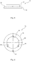
- shows a side view of a cover of the hookah closure system of
figure 1 ; - Fig. 6
- shows a top view of the cover of
figure 5 ; - Fig. 7
- shows a side view of a lower closure member of the hookah closure system of
figure 1 ; - Fig. 8
- shows a top view of the lower closure member of
figure 7 ; - Fig. 9
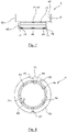
- shows a side view of an actuating member of the hookah closure system of
figure 1 ; and - Fig. 10
- shows a top view of the activating member of
figure 9 . - In the following detailed description of preferred embodiments of the present invention a hookah closure system is generally indicated with the
reference numeral 1. - Referring to
Figure 1 , theHookah closure system 1 in an example embodiment is shown in an exploded view. The example embodiment of theHookah closure system 1,Figure 1 comprises an upper closure member, alower closure member 5, and an actuatingmember 7 as main components. As can be further seen in the example embodiment of theHookah closure system 1 inFigure 1 , theHookah closure system 1 further comprises aslide lock 9 in the form of a guiding pin that is part of a sliding guide means 63 for securing and releasing theHookah closure system 1 which will be explained later on. Further, apressure spring 11 of a biasing means and a lockingball 13 of a catch mechanism is shown. Additionally, theHookah closure system 1 according toFigure 1 comprises aforce transmitter 15 in the form of a cover arranged in between the lower andupper closure members Hookah closure system 1 according to the present invention and preferred embodiments of the single components will be explained under reference toFigures 2-10 . - In
Figures 2-4 , theupper closure member 3 is shown in different views. Theupper closure member 3 is essentially manufactured as a solid piece, in particular made out of metal or plastics and essentially comprises a cylindrical shape. As can be best seen inFigure 4 , theupper closure member 3 comprises acentral channel 17 for connecting to a Hookah stem (not shown) and for providing fluid communication between the Hookah stem and a water container to be attached to thelower closure member 5. Thechannel 17 may comprise athread 19 at least section-wisely provided for attachment of the Hookah stem. Additionally, twofurther channels channels thread 25 for easy attachment of the respective components. In thechannel 17, anotherthread 27 may be arranged on an opposite end of thechannel 17, for example for connecting to a steel pipe (not shown). - In general, the upper closure member consists of two
cylinder sections surface 33 protruding the outer diameters of thecylinder sections upper cylinder section 29 essentially serves for connecting to the Hookah equipment, such as the Hookah hose, the Hookah stem and potentially an adapter cone for ventilation. Thelower cylinder section 31 has the function to form the connection with thelower closure member 5 and is designed such that it may be translationally inserted into a corresponding opening 35 (Figure 7, 8 ) of thelower closure member 5. - On the outer circumference of the lower
cylindrical section 31 which has a lesser diameter than the uppercylindrical section 29 an assembling aid which, in general, is referred to by thereference numeral 37 in the form of threeprotrusions 39 is formed. According to the present invention, the assemblingaid 37 not only serves to facilitate assembly and disassembly, in particular to prohibit false assembly, but also for locking theHookah closure system 1. Locking theHookah closure system 1 is realized by securely and releasably attaching the upper andlower closure members - Now referring to
Figures 7 and 8 , thelower closure member 5 is shown in detail. Thelower closure member 5 is essentially manufactured in the form of a rotational sleeve with a ringcylindrical wall 41 that comprises a stepped shape consisting of alower ring cylinder 43 having a bigger diameter to be faced in the water container and aring cylinder 45 essentially for connecting with theupper closure member 3, in particular with the lowercylindrical section 31. Thering cylinder 43 delimits anopening 47 for receiving a connection section of the water container. As can be best seen in the top view of thelower closure member 5 inFigure 8 , thelower closure member 5 comprises the counterparts of the assemblingaid 37 in the form ofnotches 49 provided on aninner circumference 51 of thering cylinder 45 delimiting theassembly opening 35. - When comparing
Figures 2-4 withFigures 7-8 , the functioning of the assemblingaid 37 becomes clear. When translationally mounting the upper andlower closure members upper closure member 3 into thelower closure member 5, the upper closure member-sidedprotrusions 39 engage the lower closure member-sided notches 49. In order to enable and ensure assembly of the upper andlower closure members upper closure member 5 has to be adapted. In other words, the lower andupper closure member assembly aid 37 comprises threeprotrusions 39 and three form-correspondingnotches 49, three predetermined relative orientations are provided. - Referring to
Figures 9 and 10 , the actuatingmember 7 is shown in detail. The actuatingmember 7 is realized as a rotational sleeve with aninner locking ring 53 and asleeve jacket 55 delimiting anopening 57 for receiving thelower closure member 5. The inner diameter of theopening 57 is adapted with regard to the outer diameter of theclosure member 5, in particular thering cylinder 41. Firstly, the lockingring 53 is arranged and dimensioned to be laid on top of atop ring surface 59 of thelower closure member 5 and further serves to cooperate with the assemblingaid 37 in order to secure the upper andlower closure members sleeve jacket 55 may have a truncated cone-shapedsection 60 increasing in diameter which improves usability of the actuatingmember 7. - The locking
ring 53 comprises threeindentations 61, each allocated to the protrusion-notch-structure notches 49, such that theindentations 61 may form a continuous groove or path with thenotches 49 in order to allow passage of theprotrusions 39 in an assembly state, respectively disassembly state of theclosure system 1. Theindentations 61 may also be oriented rotationally offset with regard to thenotches 49 in order to secure the upper andlower closure members Hookah closure system 1. In other words, in order to enable assembly of the lower andupper closure members member 7 is to be brought into its passive state in which the upper closure member may be assembled and disassembled from thelower closure member 5. This is realized by positioning theindentations 61 in vertical alignment with thenotches 49 so as to provide a continuous guiding path for thenotches 39. When the actuatingmember 7 is brought in its active state in which theupper closure member 5 is secured to thelower closure member 5 against disassembly and in which theupper closure member 3 may not be mounted to thelower closure member 5, a rotational or circumferential offset between theindentation 61 and thenotches 49 is adjusted. On the one hand, then, the lockingring 53 blocks the guiding path, respectively, the opening into thenotches 49 such that theprotrusions 39 may not engage thenotches 49. Further, if the upper andlower closure members member 7 is brought in its active state and theindentations 7 are not aligned with thenotches 49, the lockingring 53 now blocks the guiding path, respectively the exit of thenotches 49 in order to prohibit disassembly of the upper andlower closure members - Again referring to
Figures 7, 8 and9, 10 , the sliding guide means 63 of theHookah closure system 1 according to another aspect of the present invention is described. Via the sliding guide means 63, switching between the active state and passive state of the actuatingmember 7 is realized, respectively performed. For example, when rotating the actuatingmember 7 clockwise, the active state is achieved in order to secure the upper andlower closure members member 7 anti-clockwise, the passive state is reached in which assembly, respectively disassembly, of the upper andlower closure members - In the example embodiment, as shown in the Figures, the sliding guide means 63 comprises a
slot 65 arranged in the actuatingmember 7, in particular in itslocking ring 53. The sliding guide means 63 further comprises the slide block in the form of theslide pin 9, as shown inFigure 1 , which is to be fixedly attached to thelower closure member 5. In order to attach the guidingpin 9 to thelower closure member 5, anopening 67 is provided in atop face 69 of thelower closure member 5 facing in the upwards, vertical direction. The guidingpin 9 may be press-fittingly arranged within theopening 67. - Upon actuating the actuating
member 7 in order to switch between the active and passive state of the actuatingmember 7, theslide block pin 9 is guided within theslot 65. Theslot 65 is curved in the circumferential direction in order to enable smooth and guided passage of the guidingpin 9. When mounting the actuatingmember 7 to thelower closure member 5, the orientation of the actuatingmember 7 with regard to thelower closure member 5 must be such that the guidingpin 9 is received within theslot 65. For example, the guidingpin 9 vertically, respectively axially protrudes theclocking ring 53. Theslot 65 provides two end positions, in particular rotational end positions, corresponding to the active and passive state. In other words, the circumferential extension of theslot 65 defines the possible relative movement, in particular relative rotational movement, of the actuatingmember 7 with regard to thelower closure member 5. Further, the circumferential extension of theslot 5 defines the necessary relative actuation movement of the actuatingmember 7 for engaging the active, respectively passive state. For example, the circumferential extension of theslot 65 may be in the range of 50° to 45°, in particular be 30°. - The
Hookah closure system 1 according to an example embodiment of the present invention further comprises acatch mechanism 71 providing, respectively defining, two latching positions, one corresponding to the passive state of the actuating member and one corresponding to the active state of the actuatingmember 7. Thecatch mechanism 71 comprises, for example, two circumferentially spaceddepressions 73 arranged on thetop surface 69 of thelower closure member 5. Further, thecatch mechanism 71 comprises a movable member such as the lockingball 13 shown inFigure 1 which engages thedepression 73 to latch or snap into the two end positions defining the active and passive state of the actuatingmember 7. The lockingball 13 is mounted via ahole 75 in the lockingring 53 of the actuatingmember 7 when the actuatingmember 7 is mounted to thelower closure member 5. - In a further example embodiment of the present invention, as shown in
Figures 5 and 6 , theHookah closure system 1 comprises a biasing means which is configured to cooperate with thecatch mechanism 71 in order to apply a pretensioning force into the latching positions, respectively in order to provide resistibility against actuation of the actuatingmember 7 when the latching positions are engaged. For example, the biasing means may comprise apressure spring 11 also received within thehole 75 in the lockingring 53 after the lockingball 13 has been mounted. Theforce transmitter 15, preferably provided in the form of a rotational sleeve, is shown inFigures 5 and 6 , acts on thepressure spring 13 in order to press the spring 30 for pretensioning the lockingball 13 into one of the resting positions provided by thedepressions 73. - In the assembly state, the
sleeve 15 is mounted to thelower closure member 5 in theactuating members 7 such that alower ring 77 is received within theopening 35 of thelower closure member 5 and anupper ring 79 having a bigger diameter then thelower ring 77 is received within anopening 81 delimited in the axial direction by the lockingring 53 and in the rotational direction by thesleeve jacket 55. As can be seen in particular inFigure 6 , theforce transmitter sleeve 15 also comprisesgrooves 83 provided on aninner circumference 85 of thering notches 49 and theindentations 61 in terms of circumferential orientation, shape and dimension. Ahole 87 provided on theupper ring 79 is allocated to the guidingpin 9 such that in the assembly state, the guidingpin 9 is received from the bottom within thehole 87. This means that when actuating the actuatingmember 7, theforce transmitter sleeve 15 is rotated together with the actuatingmember 7. In order to bias thepressure spring 11 in order to pretension the movable member within the latching positions, thepressure spring 11 is dimensioned such that it actually protrudes thehole 87 in the actuatingmember 7 and such that theforce transmitter sleeve 15 may act with aflat ring surface 89 onto thepressure spring 11 to compress thepressure spring 11 in the axial/vertical direction. - From
Figures 8 and10 , it is clear that the circumferential extension of theslot 65 corresponds to the circumferential distance between the twodepressions 73 defining the two latching positions that correspond to the active and passive state of the actuatingmember 7. - The features disclosed in the above description, the figures and the claims may be significant for the realization of the invention in its different embodiments individually as in any combination.
-
- 1
- closure system
- 3
- upper closure member
- 5
- lower closure member
- 7
- actuating member
- 9
- guiding pin
- 11
- pressure spring
- 13
- locking ball
- 15
- force transmitter sleeve
- 17, 21, 23
- channel
- 19, 25, 27
- thread
- 29, 31
- cylinder section
- 33
- abutment surface
- 35
- opening
- 37
- assembling aid
- 39
- protrusion
- 41
- ring cylindrical wall
- 43, 45
- ring cylinder
- 47
- opening
- 49
- notch
- 51
- inner circumference
- 53
- locking ring
- 55
- sleeve jacket
- 57
- opening
- 59
- top ring surface
- 60
- truncated cone-shaped section
- 61
- indentation
- 63
- sliding guide means
- 65
- slot
- 67
- opening
- 69
- top surface
- 71
- catch mechanism
- 73
- depression
- 75
- hole
- 77, 79
- ring
- 81
- opening
- 83
- groove
- 85
- inner circumference
- 87
- hole
- 89
- force transmitting surface
Claims (15)
- Closure system (1) for a hookah, comprising an upper closure member (3) configured to be connected to a hookah hose and/or a hookah stem and a lower closure member (5) configured to be connected to a water container, an assembling aid (37) having an assembly state in which assembly of the upper and lower closure members with each other is enabled and a blocking state in which assembly of the upper and lower closure members with each other is disabled, and an actuating member (7) configured to cooperate with the assembling aid (37) in order to secure the upper and lower closure members to each other.
- Closure system (1) according to claim 1, wherein the assembling aid (37) is realized by a corresponding, particularly form-fitting, protrusion-notch-structure arranged on the upper and lower closure members.
- Closure system (1) according to claim 1 or 2, wherein the protrusion-notch-structure is realized by at least one upper closure member-sided protrusion and/or notch and by at least one lower closure member-sided notch and/or protrusion, which engage with each other upon mounting the upper closure member (3) with the lower closure member, wherein particularly the notch is oriented in the lengthwise direction of the respective closure member.
- Closure system (1) according to any of the preceding claims, wherein the assembling aid (37) defines a guiding assembly path and/or an axial stop defining an axial end assembly position of the upper closure member (3) with regard to the lower closure member.
- Closure system (1) according to any of the preceding claims, wherein the upper and lower closure members are configured such that the upper closure member (3) may be inserted into the lower closure member (5) in a telescope-manner and wherein the assembling aid (37) comprises at least two protrusions arranged on an outer circumference of the upper closure member (3) and at least two notches, particularly extending in the lengthwise direction of the lower closure member, arranged on an inner circumference of the lower closure member, wherein particularly upon mounting the upper closure member (3) with the lower closure member (5) each protrusion engages with one notch.
- Closure system (1) according to any of claims 2 to 5, wherein the actuating member, when securing the upper and lower closure members to each other, engages the protrusion-notch-structure in particular such that the notch or guiding path is blocked in order to prevent relative movement of the upper and lower closure members.
- Closure system (1) according to any of the preceding claims, wherein the actuating member (7) is a rotational sleeve with an inner locking ring (53) configured to engage the assembling aid, in particular the protrusion-notch-structure.
- Closure system (1) according to claim 7, wherein the locking ring (53) comprises at least one indentation allocated to the protrusion-notch-structure such that the indentation may form a continuous groove or path with the notch in order to allow passage of the protrusion and/or such that the indentation is rotationally offset with regard to the notch in order to secure the upper and lower closure members to each other.
- Closure system (1), in particular according to one of the preceding claims, for a hookah, comprising an upper closure member (3) configured to be connected to a hookah hose and/or a hookah stem, a lower closure member (5) configured to be connected to a water container, and an actuating member (7) that has a passive state, in which the upper closure member (3) may be disassembled from the lower closure member, and an active state, in which the upper closure member (3) is secured to the lower closure member (5) against disassembly, wherein switching between the active and the passive state is performed via a sliding guide means.
- Closure system (1) according to claim 9, wherein the sliding guide means (63) is realized by a slot arranged in the actuating member (7) and a slide block arranged on the lower closure member, wherein particularly the slide block is press-fittingly mounted in an opening of the lower closure member.
- Closure system (1) according to claim 10, wherein upon actuating the actuating member (7) in order to switch between the active and passive state the slide block is guided within the slot between two end positions corresponding to the active and passive state.
- Closure system (1) according to any of claims 10 to 11, wherein the actuating member (7) is a rotational sleeve and the slot extends in a circumferential direction with regard to a rotational axis of the rotational sleeve, wherein particularly the circumferential extension of the slot is in the range of 15° to 45°, in particular is 30°.
- Closure system (1) according to any of the preceding claims, further comprising a catch mechanism (71) defining at least one latching position corresponding to either a passive state of the actuating member, in which the upper closure member (3) may be disassembled from the lower closure member, or an active state, in which the upper closure member (3) is secured to the lower closure member (5) against disassembly.
- Closure system (1) according to claim 13, wherein the sliding guide means (63) and the catch mechanism (71) are adapted with regard to each other, in particular such that each end position of the sliding guide means (63) is allocated to a latching position of the catch mechanism, and/or wherein the catch mechanism (71) cooperates with a biasing means providing a resistibility against actuation of the actuating member.
- Hookah comprising a closure system (1) according to any of the preceding claims.
Priority Applications (1)
| Application Number | Priority Date | Filing Date | Title |
|---|---|---|---|
| EP20203671.1A EP3987944A1 (en) | 2020-10-23 | 2020-10-23 | Hookah closure system |
Applications Claiming Priority (1)
| Application Number | Priority Date | Filing Date | Title |
|---|---|---|---|
| EP20203671.1A EP3987944A1 (en) | 2020-10-23 | 2020-10-23 | Hookah closure system |
Publications (1)
| Publication Number | Publication Date |
|---|---|
| EP3987944A1 true EP3987944A1 (en) | 2022-04-27 |
Family
ID=73014354
Family Applications (1)
| Application Number | Title | Priority Date | Filing Date |
|---|---|---|---|
| EP20203671.1A Withdrawn EP3987944A1 (en) | 2020-10-23 | 2020-10-23 | Hookah closure system |
Country Status (1)
| Country | Link |
|---|---|
| EP (1) | EP3987944A1 (en) |
Citations (4)
| Publication number | Priority date | Publication date | Assignee | Title |
|---|---|---|---|---|
| DE202012005521U1 (en) * | 2012-06-06 | 2013-09-09 | Chunga UG (haftungsbeschränkt) | Hookah with a smoke column and one of these associated liquid container |
| DE202014102447U1 (en) * | 2014-05-26 | 2014-09-29 | Ibrahim Dabes | Distributor for a hookah |
| DE202015007964U1 (en) * | 2014-10-22 | 2016-01-14 | Schmidt Innovations GmbH | Closure system for a hookah |
| US20180084825A1 (en) * | 2016-09-29 | 2018-03-29 | Schmidt Innovations GmbH | Closure system for a hookah |
-
2020
- 2020-10-23 EP EP20203671.1A patent/EP3987944A1/en not_active Withdrawn
Patent Citations (4)
| Publication number | Priority date | Publication date | Assignee | Title |
|---|---|---|---|---|
| DE202012005521U1 (en) * | 2012-06-06 | 2013-09-09 | Chunga UG (haftungsbeschränkt) | Hookah with a smoke column and one of these associated liquid container |
| DE202014102447U1 (en) * | 2014-05-26 | 2014-09-29 | Ibrahim Dabes | Distributor for a hookah |
| DE202015007964U1 (en) * | 2014-10-22 | 2016-01-14 | Schmidt Innovations GmbH | Closure system for a hookah |
| US20180084825A1 (en) * | 2016-09-29 | 2018-03-29 | Schmidt Innovations GmbH | Closure system for a hookah |
Similar Documents
| Publication | Publication Date | Title |
|---|---|---|
| US6257278B1 (en) | High pressure fluidline connector | |
| US5494073A (en) | Fluid connector | |
| EP2150744B1 (en) | Quick-coupling valve, particularly for pressurized fluids | |
| KR101545334B1 (en) | Improvements in or relating to tube coupling | |
| EP2425172B1 (en) | Interlock system for valve coupling | |
| US5607139A (en) | Coupling for coupling together hoses or pipes for a pressure medium | |
| US7195286B2 (en) | Tube joint | |
| US4641859A (en) | Coupling having spring biased locking means | |
| KR960038213A (en) | Tube connection for easy connection and disconnection | |
| US5116086A (en) | Quick action coupling | |
| US12042808B2 (en) | Quick connect shower head | |
| US20070199616A1 (en) | Adapter for an anesthetic vaporizer | |
| USRE38786E1 (en) | Tube couplings | |
| US20130037141A1 (en) | Transmission anti-leak valve | |
| US4792162A (en) | Protective device for quick connect coupling | |
| CA2631208A1 (en) | Tube fitting with indication of fit | |
| GB2264340A (en) | A plug-in coupling for joining fluid conduits | |
| EP1882877A2 (en) | Device for quick connection of two components of systems for the distribution of liquids or gases, with high safety against tampering | |
| KR20230051100A (en) | Coupling Device with Valves | |
| US5566987A (en) | Hose fitting assembly | |
| KR100235820B1 (en) | Pipe Fittings and Locks for Pipe Fittings | |
| US5109887A (en) | Multiway valve | |
| JP3214479U (en) | Sockets and fittings | |
| JP2019108976A (en) | Pipe joint | |
| JP2010025205A (en) | Adapter |
Legal Events
| Date | Code | Title | Description |
|---|---|---|---|
| PUAI | Public reference made under article 153(3) epc to a published international application that has entered the european phase |
Free format text: ORIGINAL CODE: 0009012 |
|
| STAA | Information on the status of an ep patent application or granted ep patent |
Free format text: STATUS: THE APPLICATION HAS BEEN PUBLISHED |
|
| AK | Designated contracting states |
Kind code of ref document: A1 Designated state(s): AL AT BE BG CH CY CZ DE DK EE ES FI FR GB GR HR HU IE IS IT LI LT LU LV MC MK MT NL NO PL PT RO RS SE SI SK SM TR |
|
| STAA | Information on the status of an ep patent application or granted ep patent |
Free format text: STATUS: THE APPLICATION IS DEEMED TO BE WITHDRAWN |
|
| 18D | Application deemed to be withdrawn |
Effective date: 20221028 |