EP3987147B1 - Bohrlochwerkzeug mit kraftstoffsystem - Google Patents
Bohrlochwerkzeug mit kraftstoffsystem Download PDFInfo
- Publication number
- EP3987147B1 EP3987147B1 EP20734169.4A EP20734169A EP3987147B1 EP 3987147 B1 EP3987147 B1 EP 3987147B1 EP 20734169 A EP20734169 A EP 20734169A EP 3987147 B1 EP3987147 B1 EP 3987147B1
- Authority
- EP
- European Patent Office
- Prior art keywords
- tool
- fuel
- weight
- oxidant
- chamber
- Prior art date
- Legal status (The legal status is an assumption and is not a legal conclusion. Google has not performed a legal analysis and makes no representation as to the accuracy of the status listed.)
- Active
Links
Images

Classifications
-
- E—FIXED CONSTRUCTIONS
- E21—EARTH OR ROCK DRILLING; MINING
- E21B—EARTH OR ROCK DRILLING; OBTAINING OIL, GAS, WATER, SOLUBLE OR MELTABLE MATERIALS OR A SLURRY OF MINERALS FROM WELLS
- E21B29/00—Cutting or destroying pipes, packers, plugs or wire lines, located in boreholes or wells, e.g. cutting of damaged pipes, of windows; Deforming of pipes in boreholes or wells; Reconditioning of well casings while in the ground
- E21B29/02—Cutting or destroying pipes, packers, plugs or wire lines, located in boreholes or wells, e.g. cutting of damaged pipes, of windows; Deforming of pipes in boreholes or wells; Reconditioning of well casings while in the ground by explosives or by thermal or chemical means
-
- E—FIXED CONSTRUCTIONS
- E21—EARTH OR ROCK DRILLING; MINING
- E21B—EARTH OR ROCK DRILLING; OBTAINING OIL, GAS, WATER, SOLUBLE OR MELTABLE MATERIALS OR A SLURRY OF MINERALS FROM WELLS
- E21B43/00—Methods or apparatus for obtaining oil, gas, water, soluble or meltable materials or a slurry of minerals from wells
- E21B43/11—Perforators; Permeators
- E21B43/119—Details, e.g. for locating perforating place or direction
-
- C—CHEMISTRY; METALLURGY
- C06—EXPLOSIVES; MATCHES
- C06B—EXPLOSIVES OR THERMIC COMPOSITIONS; MANUFACTURE THEREOF; USE OF SINGLE SUBSTANCES AS EXPLOSIVES
- C06B25/00—Compositions containing a nitrated organic compound
-
- E—FIXED CONSTRUCTIONS
- E21—EARTH OR ROCK DRILLING; MINING
- E21B—EARTH OR ROCK DRILLING; OBTAINING OIL, GAS, WATER, SOLUBLE OR MELTABLE MATERIALS OR A SLURRY OF MINERALS FROM WELLS
- E21B43/00—Methods or apparatus for obtaining oil, gas, water, soluble or meltable materials or a slurry of minerals from wells
- E21B43/11—Perforators; Permeators
- E21B43/114—Perforators using direct fluid action on the wall to be perforated, e.g. abrasive jets
-
- C—CHEMISTRY; METALLURGY
- C06—EXPLOSIVES; MATCHES
- C06B—EXPLOSIVES OR THERMIC COMPOSITIONS; MANUFACTURE THEREOF; USE OF SINGLE SUBSTANCES AS EXPLOSIVES
- C06B43/00—Compositions characterised by explosive or thermic constituents not provided for in groups C06B25/00 - C06B41/00
Definitions
- the present invention relates to a tool for manipulating a material.
- the invention finds particular application in the oil and gas industry and is particularly suitable for the manipulation of solid materials for example tubulars, such as casing or production tubing, in a downhole environment.
- the change may be a change to one or more of temperature, structure, position, composition, phase, physical properties and/or condition of the target or any other characteristic of the target.
- a typical situation may be to sever a tubular in a well, clean a downhole device or tubulars, initiate a downhole tool or remove an obstruction.
- Conventional tools perform these operations with varying degrees of success but generally they are not particularly efficient and make such operations expensive and time consuming.
- a deflagrating propellant is generally classified as an explosive material which has a low rate of combustion and once ignited burns or otherwise decomposes to produce propellant gas. This gas is highly pressurised, the pressure driving the gas and other combustion products away from the propellant, forming a stream of combustion products.
- a propellant can burn smoothly and at a uniform rate after ignition without depending on interaction with the atmosphere and produces propellant gas and/or heat on combustion; and may also produce additional combustion products.
- a tool for manipulating a material comprising:
- the tool may be a downhole tool for use in oil and/or gas wells.
- the manipulation of a material may be a change in temperature, structure, position, composition, phase, physical properties and/or condition of the material; or any other characteristic of the material making up the target.
- the change in the material may be to, for example, ablate, erode, impact, clean and/or transmit heat.
- Severing or perforating the material of a target e.g. severing a tubular is an exemplary use.
- the tool may find use in removing lengths of tubular downhole.
- the tool may find use in perforating a tubular in multiple locations along its axial length downhole.
- the removal of lengths of tubular, or perforation of a tubular may be carried out in an ablative fashion.
- Fuel and oxidant mixtures described herein can act to remove metal from a tubular by ablating it into fine particles or droplets that are blasted away by the combustion jet or by a decomposition product jet from a monopropellant.
- the metal of the tubular may even be combusted (oxidised) during its removal.
- Such uses can serve as alternatives to conventional milling techniques that may be relatively expensive and time consuming.
- the combustion jet may be employed to repair a target, for example by depositing a coating carried by the combustion jet.
- the combustion jet e.g. the heat produced
- Repair operations may include providing a cement or a fusible material such bismuth or a bismuth alloy from the tool or from another source.
- a tool that makes use of a suitable monopropellant such as hydrazine or a hydrazine derivative.
- Catalytic or thermal decomposition of hydrazine produces a decomposition product jet of hot gases that can be directed by the nozzle or nozzles at a target.
- the tool of the invention makes use of a fuel and oxidant mixture to produce a combustion jet.
- the combustion jet pressurises the chamber.
- the pressure and/or heat generated maybe employed to open the at least one nozzle. For example, by melting a fusible material that closes the nozzle before use. For further example by moving part of the tool relative to each other and thereby uncovering or creating the nozzle opening.
- the nozzle or nozzles may provide a combustion jet or combustion jets emanating from the tool in a radially outwards 360 degree or substantially 360 degree direction i.e. the combustion jet or jets can engage a target, such as a section of a tubular, around the circumference of its inner surface.
- a target such as a section of a tubular
- moving the tool axially within a tubular can remove a selected length of tubular.
- the nozzle or nozzles may divide the initially formed combustion jet into a plurality of directed combustion jets, each emanating in a selected direction, outwards from the tool.
- the combustion jet or jets may be used to perforate a tubular.
- the perforation(s) may be round or of any shape required for the specific application in question. Any number and combination of perforation shapes may be used in one or more operations.
- the tool may be moved axially to a new location along the length of the tubular to make further perforations.
- the combustion process may be halted and then subsequently restarted after moving the tool to a new location. Alternatively, the combustion process may continue as the tool is being moved.
- a tool may be rotated.
- a tool with a combustion jet emanating in one direction may be rotated so as to direct the jet in different directions around the location of the tool.
- Nozzles provided on a tool may be closable. This can be useful, for example where the tool is moved from one location to another during or after use.
- the tool may include a cooling system.
- the cooling system may be open. In an open cooling system, a supply of coolant, such as water or seawater is not reused. After cooling heated parts such as the chamber and nozzle(s) the coolant is allowed out of the tool e.g. dumped into the well when the tool is being used downhole.
- a cooling system may be closed. In a closed cooling system, the coolant is recirculated.
- the coolant (such as water or seawater) may pass round a cooling system that may include a cooling unit, to cool coolant after circulation through or past heated parts.
- a flowable fuel such as a liquid, gas, or gel may itself be circulated for use as a coolant, before being fed to the chamber and ignited.
- the fuel and oxidant mixture is supplied as a single composition including both fuel and oxidant. This may be described as a 'mono fuel' system, as only one composition is required to obtain the combustion jet. Alternatively, but not in accordance with the invention, fuel and oxidant may be provided separately (e.g. from separate tanks within the body of the tool) to be mixed either before or at the ignition point, where the combustion jet is formed in the chamber. Where a separate fuel composition and a separate oxidant composition are employed that arrangement may be termed a 'bi fuel' system.
- the fuel and oxidant mixture may be carried within the tool or may be delivered to the tool, via appropriate conduits, from any remote location, for example from storage tanks located on the surface facilities of an offshore oil and gas platform, drilling rig or well intervention vessel or from the seabed. Monopropellants may be supplied similarly.
- the combined fuel and oxidant mixtures and the fuels and oxidants employed as separate compositions are combustible but generally not explosive i.e. not classified as explosives ("Class 1") for transport under dangerous goods regulations. This can make handling and transport of these materials, and tools containing these materials, less hazardous and generally simpler. Where separate fuel and oxidant compositions are provided for mixing in the tool, one or both of these may be classified as non-combustible, until the mixture is made.
- the fuel may be a solid, liquid, slurry, gel or gas.
- the oxidant may be a solid, liquid, slurry, gel or gas.
- a monopropellant or mixture of fuel and oxidant might be a solid, liquid, slurry, gel or gas.
- the compositions employed for fuel, oxidant, combined fuel and oxidant mixture, or monopropellant are flowable.
- Solid particles may be contained within liquids, slurries or gels; or even in gases (as an aerosol).
- Metal particles can serve as a fuel, increasing combustion temperatures and density. In some examples they may act as a catalyst for combustion processes.
- particulate solids as principal or even sole fuel or oxidant may be contemplated in some instances, for example propelled by gas in the form of an aerosol.
- Gel compositions of fuel, oxidant and/or a fuel and oxidant mixture can provide advantages.
- Gel compositions can have their viscosity controlled to suit delivery and combustion conditions found in the downhole or other relatively harsh environments.
- a gel 'mono fuel', or a gel 'bi fuel' where one or both of oxidant composition and fuel composition are gels can be convenient in use.
- Examples of fuel substances that may be employed in a fuel or fuel and oxidant composition include ionic liquids, or solutions, comprising quaternary ammonium salts, such as alkyl quaternary ammonium salts, for example ethyl ammonium nitrate.
- a hydrocarbon composition such as a paraffin (hydrocarbon) mixture and/or an alcohol and/or a nitro alkane and/or a nitroalkene and/or an alkyl nitrate may be employed in a fuel.
- the oxidant may be supplied separately (as a 'bi fuel') and may be a gas, such as air or oxygen or a liquid such as cryogenic oxygen or nitric acid.
- a paraffin mixture and/or an alcohol and/or a nitroalkane and/or a nitroalkene and/or an alkyl nitrate may be used as a fuel component or fuel components in mono fuel compositions.
- Alcohols, nitroalkanes and alkyl nitrates when employed, may be C1 to C10 alcohols, nitroalkanes and alkyl nitrates.
- a fuel and oxidant mixture is a composition comprising an ionic liquid and a source of additional oxygen, such as a nitrate perchlorate, chlorate, chromate or dinitramide salt, or mixtures thereof.
- a source of additional oxygen such as a nitrate perchlorate, chlorate, chromate or dinitramide salt, or mixtures thereof.
- a nitrate perchlorate, chlorate, chromate or dinitramide salt or mixtures thereof.
- a source of additional oxygen such as a nitrate perchlorate, chlorate, chromate or dinitramide salt, or mixtures thereof.
- a source of additional oxygen such as a nitrate perchlorate, chlorate, chromate or dinitramide salt, or mixtures thereof.
- lithium nitrate, lithium perchlorate or ammonium dinitramide lithium nitrate, lithium perchlorate or ammonium dinitramide.
- a gel comprising
- a further example of a mono fuel composition is a composition comprising an alcohol, such as ethanol, and a source of additional oxygen, such as a nitrate, perchlorate, chlorate, chromate or dinitramide salt, or mixtures thereof.
- a yet further example of a mono fuel composition is a composition comprising a nitroalkane and/or a nitroalkene and/or an alkyl nitrate; and a source of additional oxygen, such as a nitrate, perchlorate, chlorate, chromate or dinitramide salt, or mixtures thereof. If a nitroalkane is used nitromethane may be employed. If an alkyl nitrate is used isopropyl nitrate (IPN) may be used.
- IPN isopropyl nitrate
- any gelling agent compatible with the other components of the composition can serve.
- gelling agents include polyacrylic acid polymers, such as the Carbopol ® polymers available from The Lubrizol Corporation of Wickliffe Ohio USA.
- Alternatives may include fumed silica e.g. Aerosil ® fumed silicas available from Evonik industries AG of Essen, Germany. More than one gelling agent may be employed.
- the fuel and oxidant compositions may have additives to enhance performance in manipulating a target material such as a tubular.
- particles such as aluminium or other metal particles may be provided, suspended in a fuel and oxidant mixture, a fuel composition or even an oxidant composition.
- Gel compositions and mixtures are convenient in avoiding settling out of particles.
- Metal particles such as aluminium can provide the benefit of increasing the density of fuel compositions allowing the tools and any associated storage tanks to be more compact.
- Aluminium particles may serve a dual purpose. As a reactive metal aluminium may contribute to the combustion process, forming aluminium oxide. The aluminium itself or the aluminium oxide formed may act as a heat transfer agent or even an abrasive in attacking a target material.
- reactive metals or elements may be employed in place of or in addition to aluminium.
- magnesium, iron or boron where more than one reactive metal or element is employed, they can be used as mixtures and/or as alloys.
- magnalium (an alloy of magnesium and aluminium) or other aluminium alloys may be used. Magnalium containing about 5% magnesium and 95% aluminium by weight may be used. More generally the use of one or more of aluminium, beryllium, iron, zirconium, magnesium, boron and/or boron carbide is contemplated.
- particles may have diameters of less than 100 ⁇ m of even below 60 ⁇ m, typically from 10-45 ⁇ m. However, for some uses nano-particles may be employed. For example, having diameters of 100nm or less. Particles may be coated (for example to aid dispersion in a liquid or gel) or uncoated.
- Particles may also be supplied separately in the tool for introduction into the combustion jet or for introduction into the fuel, the oxidant or a combined oxidant and fuel composition, before the ignition of the mixture.
- Conveniently particles may be supplied suspended in a liquid, for example particles such as aluminium particles may be supplied suspended in a liquid or gel phase, for example in dioctyl adipate.
- the at least one source provides pressurised fuel and oxidant (together when in accordance with the invention or separately) into the chamber.
- gas pressure may be used to drive the fluid(s) into the chamber.
- a container containing the liquid or gel with an inert gas such as nitrogen.
- a cylinder contained within or attached to the tool may supply a gas pressure (e.g. of nitrogen).
- gas pressure may be supplied via hose connections to the tool.
- a solid is employed as fuel or oxidant it may be delivered as a pressurised aerosol.
- a monopropellant may be supplied in similar ways.
- one or more pumps may be employed to pressurise the combustion mixture or its separate components.
- the use of hydraulic or pneumatic systems e.g. a piston moved by hydraulic fluid) to provide pressure is also contemplated.
- the delivery of fuel, oxidant, fuel and oxidant mixture, or monopropellant to the chamber is via an injector device that may control the input to the chamber and may include a mixing head for mixing fuel and oxidant together.
- the fuel and oxidant mixture is finely dispersed by the injector device i.e. the injector device comprises a plurality of injector nozzles through which the fuel and oxidant mixture flow before ignition on entry to the chamber.
- the injector device decouples the combustion jet from the source of pressurized fuel and oxidant mixture.
- Ignition may be by any suitable means for the compositions employed. Ignition may be by electrical discharge or laser. As another alternative electrically powered or laser ignition (for example in the chamber) may be used to ignite a primer composition, that ignites more readily than the fuel and oxidant mixture.
- a primer composition such as potassium perchlorate or ammonium perchlorate may be provided in the chamber and ignited to provide an initial combustion, heat and pressure that will ignite the fuel and oxidant supplied to the chamber via the injector device.
- the primer composition may be provided as a charge (or several charges) installed in a separate chamber connected to the combustion chamber.
- the initial ignition sequence associated with the primer composition may be electro-explosive based, using a known RF safe oilfield igniter system.
- the initial ignition sequence may be delivered using a percussion igniter which is insensitive to electrical impulse, but rather has an impact sensitivity requiring a striking pin to be actuated above it.
- a monopropellant such as hydrazine may be ignited by a catalyst or thermally.
- the combustion jet may be enhanced or moderated in various ways, in addition to those discussed above making use of particles.
- the combustion jet may have additional fuel and/or oxidant injected into it from a source, that may be the same source that supplies the fuel and oxidant.
- the tool may further comprise one or more control modules, which may control the mono fuel or bi fuel supply, additives supply, combustion chamber pressure and temperature and discharge pressure and temperature.
- Control modules may contain one or more items such as components for: an electrical or laser ignition system; control of gas pressures (that may be adjustable in response to monitoring of combustion temperatures); and other items such as a pump for pressurising the fuel, the oxidant, or a fuel and oxidant mixture.
- the present invention provides a method of manipulating a material, the method comprising:
- the method may make use of any embodiments of the tool as described herein.
- the method may make use of any embodiment of the fuel and oxidant compositions as described herein.
- the ionic liquid may comprise a quaternary ammonium salt such as an alkyl quaternary ammonium salt, or a mixture of quaternary ammonium salts.
- the quaternary ammonium salt may be ethyl ammonium nitrate.
- a fuel comprising a quaternary ammonium salt such as an alkyl quaternary ammonium salt, or a mixture of quaternary ammonium salts.
- the quaternary ammonium salt may be ethyl ammonium nitrate.
- a fuel and oxidant mixture comprising a quaternary ammonium salt such as an alkyl quaternary ammonium salt, or a mixture of quaternary ammonium salts as fuel and a nitrate, perchlorate chlorate, chromate or dinitramide salt or mixtures thereof as oxidant.
- a quaternary ammonium salt such as an alkyl quaternary ammonium salt, or a mixture of quaternary ammonium salts as fuel and a nitrate, perchlorate chlorate, chromate or dinitramide salt or mixtures thereof as oxidant.
- lithium nitrate and/or lithium perchlorate salts may be employed.
- Mixtures of salts for example mixtures of nitrate salts, mixtures of perchlorate salts and/or a mixture comprising one or more nitrate salt and one or more perchlorate salt may be employed as oxidant.
- the quaternary ammonium salt may
- a fuel and oxidant mixture comprising an alcohol, such as ethanol, as fuel and a nitrate, perchlorate chlorate, chromate or dinitramide salt, or mixtures thereof as oxidant.
- a fuel and oxidant mixture comprising a nitroalkane, a nitroalkene, an alkyl nitrate, or mixtures thereof, as fuel and a nitrate, perchlorate chlorate, chromate or dinitramide salt, or mixtures thereof as oxidant.
- Nitromethane may be used.
- Isopropyl nitrate may be used.
- Gel fuel and oxidant mixtures may comprise:
- the alcohol may be a C1 to C10 alcohol with one or more hydroxyl groups.
- a glycol or other polyhydric alcohol may be used, for example ethylene glycol.
- the alcohol can aid in dissolution of the oxidant and lower the freezing point of the composition.
- a nitrate salt, such as lithium nitrate may be used.
- the gelling agent may comprise polyacrylic acid polymers and/or fumed silica. If a gel composition is not required, the gelling agent may be omitted. Other additives may be included However, compositions A may consist essentially of or consist only of the components listed above.
- a preferred composition A is as follows: % by weight Component 59 ethyl ammonium nitrate (ionic liquid) 15 lithium nitrate 15 aluminium particles 10 ethylene glycol 1 Carbolpol ® (polyacrylic acid polymer)
- Gel fuel and oxidant mixtures may comprise:
- the gelling agent may comprise polyacrylic acid polymers and/or fumed silica. If a gel composition is not required, the gelling agent may be omitted. Other additives may be included. However, compositions B may consist essentially of or consist only of the components listed above.
- a preferred composition B is as follows: % by weight Component 45 lithium perchlorate 40 ethanol 14 aluminium particles 0.8-1 Carbolpol ® (polyacrylic acid polymer)
- Gel fuel and oxidant mixtures may comprise
- a nitroalkane employed may be a C1 to C10 nitroalkane.
- a nitroalkene may be a C2 to C10 nitroalkene, for example nitroethylene.
- the nitroalkane may be nitromethane. If an alkylnitrate is used it may be a C1 to C10 alkyl nitrate such as isopropyl nitrate.
- the alcohol may be a C1 to C10 alcohol with one or more hydroxyl groups.
- the alcohol may be a butyl alcohol, such as n-butyl alcohol. Butyl alcohol is convenient as it is a commonly employed desensitiser for nitro alkanes.
- the salt may be a perchlorate salt such as lithium perchlorate.
- the gelling agent may comprise polyacrylic acid polymers and/or fumed silica. If a gel composition is not required, the gelling agent may be omitted. Other additives may be included However, compositions C may consist essentially of or consist only of the components listed above.
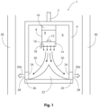
- Figure 1 shows an exemplary tool 1 in schematic cross section.
- the tool 1 is downhole in an oil or gas well.
- Connection 2 to surface includes control signal wiring.
- the tool 1 has a generally cylindrical body 4 including a chamber 6.
- a fuel source Within the chamber 6 is a fuel source, a cylinder 8 in this example.
- Cylinder 8 contains a gel fuel and oxidant mixture 9, pressurised by a charge of nitrogen gas contained within.
- a signal sent via the connection to surface 2 operates the control module 10 which commands opening of valve 12, releasing the gel fuel and oxidant mixture 9 into injector head 14.
- the mixture 9 is sprayed through injector head nozzles 16 into chamber 6 as a finely divided spray.
- Ignitor 18 provides an electrical discharge that ignites mixture 9 to form a combustion jet suggested by arrows 20.
- the combustion jet pressurises the chamber 6 and is deflected by deflector 22 towards the inlets 24 of nozzles 26 that are closed by fusible material 28.
- the heat and pressure from the combustion jet removes the fusible material 24, allowing the combustion jet 20 to escape the chamber 6 via the outlets 28 of nozzles 26 as a plurality of directed combustion jets.
- the combustion jet can then attack and perforate the walls of a tubular 30
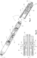
- Tool 1 is shown in two parts in figure 2 .
- Tool part 1A is shown in perspective with part of the wall of body 4 shown in ghost to allow viewing of the interior.
- Tool part 1B is shown in perspective cross section to allow viewing of the interior of the chamber 6 and related parts. In use the two parts 1A and 1B form a single generally cylindrical body 4.
- Figure 3 shows schematically an end of a tool 1 that is cylindrical and includes a plurality of nozzles 26 that extend circumferentially around the tool.
- a plurality of combustion jets exiting from nozzles 26 can provide an effect similar to that of the tool of figures 2 i.e. a (generally) circular disc of overlapping combustion jets directed more or less orthogonally from the tool.
- Figure 4 shows schematically an end of a tool 1 that is cylindrical and includes a plurality of nozzles 26 that are of the convergent-divergent type as found in aerospace rocket engines. Such a design may be employed for perforation work downhole.
Landscapes
- Geology (AREA)
- Life Sciences & Earth Sciences (AREA)
- Engineering & Computer Science (AREA)
- Mining & Mineral Resources (AREA)
- Chemical & Material Sciences (AREA)
- Geochemistry & Mineralogy (AREA)
- Fluid Mechanics (AREA)
- General Life Sciences & Earth Sciences (AREA)
- Physics & Mathematics (AREA)
- Environmental & Geological Engineering (AREA)
- Organic Chemistry (AREA)
- Chemical Kinetics & Catalysis (AREA)
- General Chemical & Material Sciences (AREA)
- Liquid Carbonaceous Fuels (AREA)
- Portable Nailing Machines And Staplers (AREA)
- Solid Fuels And Fuel-Associated Substances (AREA)
Claims (13)
- Ein Werkzeug (1) zum Manipulieren eines Materials, wobei das Werkzeug Folgendes beinhaltet:einen Körper (4), der eine Kammer (6) definiert;eine Einspritzvorrichtung (14);mindestens eine Quelle (8) einer unter Druck stehenden Mischung (9) von Brennstoff und Oxidationsmittel, die über die Einspritzvorrichtung (14) mit der Kammer (6) in Fluidverbindung steht;mindestens eine Düse (16), wobei jede Düse einen Einlass (24) und einen Auslass (28) aufweist, wobei der Einlass (24) mit der Kammer (6) in Fluidverbindung steht; undmindestens einen Mechanismus (18) zum Zünden der Mischung (9) von Brennstoff und Oxidationsmittel;wobei beim Zünden der Mischung (9) von Brennstoff und Oxidationsmittel ein Verbrennungsstrahl in der Kammer (6) gebildet wird, der im Einsatz durch jeden Düsenauslass (28) in Richtung eines zu manipulierenden Materials und in Eingriff mit diesem aus dem Werkzeug (1) herausströmt; undwobei die Mischung (9) von Brennstoff und Oxidationsmittel als eine Einzelzusammensetzung bereitgestellt ist, beinhaltend:zu 50 bis 70 Gew.-% eine ionische Flüssigkeit aus quartärem Ammoniumsalz;zu 5 bis 25 Gew.-% ein Nitrat-, Chlorat-, Chromat-, Dinitramid- oder Perchloratsalz oder Mischungen davon;zu 5 bis 25 Gew.-% mindestens ein Metall, das aus der Gruppe ausgewählt ist, die aus Aluminium, Magnesium und Legierungen von Aluminium und Magnesium besteht;zu 0 bis 20 Gew.-% einen Alkohol; und optionalzu 0,15 bis 10 Gew.-% ein Geliermittel.
- Werkzeug gemäß Anspruch 1, wobei die ionische Flüssigkeit aus quartärem Ammoniumsalz ein quartäres Alkylammoniumsalz ist.
- Werkzeug gemäß Anspruch 2, wobei das quartäre Alkylammoniumsalz Ethylammoniumnitrat ist.
- Werkzeug gemäß Anspruch 1, wobei die Mischung von Brennstoff und Oxidationsmittel Folgendes beinhaltet:zu 55 bis 65 Gew.-% eine ionische Flüssigkeit aus quartärem Ammoniumsalz;zu 10 bis 20 Gew.-% ein Nitrat-, Chlorat-, Chromat- oder Dinitramidsalz oderMischungen davon;zu 10 bis 20 Gew.-% mindestens ein Metall, das aus der Gruppe ausgewählt ist, die aus Aluminium, Magnesium und Legierungen von Aluminium und Magnesium besteht;zu 5 bis 15 Gew.-% einen Alkohol; undzu 0,5 bis 3 Gew.-% ein Geliermittel.
- Werkzeug gemäß einem der vorhergehenden Ansprüche, wobei das Werkzeug zum Einsatz unter Tage konfiguriert ist.
- Werkzeug gemäß einem der vorhergehenden Ansprüche, wobei der Verbrennungsstrahl oder die Verbrennungsstrahlen aus dem Werkzeug in einer radial nach außen gerichteten 360-Grad-Richtung austreten.
- Werkzeug gemäß einem der vorhergehenden Ansprüche, das ferner ein Kühlsystem beinhaltet.
- Werkzeug gemäß einem der vorhergehenden Ansprüche, wobei Gasdruck verwendet wird, um die Mischung von Brennstoff und Oxidationsmittel in die Kammer zu treiben.
- Werkzeug gemäß einem der vorhergehenden Ansprüche, wobei die Zusammensetzung aus Brennstoff und Oxidationsmittel ferner Folgendes beinhaltet: Partikel von mindestens einem, das aus der Gruppe ausgewählt ist, die aus Folgendem besteht:
Beryllium, Eisen, Zirconium, Bor, Borcarbid und Legierungen davon. - Ein Verfahren zum Manipulieren eines Materials, wobei das Verfahren Folgendes beinhaltet:Einbringen eines Werkzeugs gemäß einem der Ansprüche 1 bis 9 in die Nähe eines Zielmaterials; undBetreiben des Werkzeugs zum Produzieren eines Verbrennungsstrahls, der in das Zielmaterial eingreift.
- Verfahren gemäß Anspruch 10, wobei das Werkzeug ein Untertagewerkzeug ist und das Werkzeug axial innerhalb eines Rohrs zum Entfernen eines ausgewählten Rohrabschnitts bewegt wird.
- Verfahren gemäß Anspruch 10, wobei das Werkzeug ein Untertagewerkzeug ist und das Werkzeug betrieben wird, um ein Rohr an einer ausgewählten Stelle oder an ausgewählten Stellen zu perforieren, und dann bewegt wird, um das Rohr an einer weiteren ausgewählten Stelle oder an weiteren ausgewählten Stellen zu perforieren.
- Verfahren gemäß einem der Ansprüche 10 bis 12, wobei das Werkzeug im Einsatz gedreht wird, um den Verbrennungsstrahl in unterschiedliche Richtungen um die Stelle des Werkzeugs herum zu richten.
Applications Claiming Priority (2)
| Application Number | Priority Date | Filing Date | Title |
|---|---|---|---|
| GBGB1908786.5A GB201908786D0 (en) | 2019-06-19 | 2019-06-19 | Downhole tool with fuel system |
| PCT/EP2020/067246 WO2020254659A1 (en) | 2019-06-19 | 2020-06-19 | Downhole tool with fuel system |
Publications (3)
| Publication Number | Publication Date |
|---|---|
| EP3987147A1 EP3987147A1 (de) | 2022-04-27 |
| EP3987147B1 true EP3987147B1 (de) | 2025-03-19 |
| EP3987147C0 EP3987147C0 (de) | 2025-03-19 |
Family
ID=67432360
Family Applications (1)
| Application Number | Title | Priority Date | Filing Date |
|---|---|---|---|
| EP20734169.4A Active EP3987147B1 (de) | 2019-06-19 | 2020-06-19 | Bohrlochwerkzeug mit kraftstoffsystem |
Country Status (8)
| Country | Link |
|---|---|
| US (1) | US12378849B2 (de) |
| EP (1) | EP3987147B1 (de) |
| AU (1) | AU2020296310B2 (de) |
| CA (1) | CA3140293A1 (de) |
| ES (1) | ES3018933T3 (de) |
| GB (2) | GB201908786D0 (de) |
| SA (1) | SA521431154B1 (de) |
| WO (1) | WO2020254659A1 (de) |
Families Citing this family (3)
| Publication number | Priority date | Publication date | Assignee | Title |
|---|---|---|---|---|
| DE102021103380B3 (de) * | 2021-02-12 | 2021-12-16 | Deutsches Zentrum für Luft- und Raumfahrt e.V. | Treibstoff für Raketentriebwerke |
| US11885189B2 (en) * | 2021-06-15 | 2024-01-30 | Robertson Intellectual Properties, LLC | Radial cutting apparatus for cutting a downhole conduit |
| DE102023101308A1 (de) * | 2023-01-19 | 2024-07-25 | Deutsches Zentrum für Luft- und Raumfahrt e.V. | Treibstoff für raumfahrzeuge und/oder flugkörper |
Family Cites Families (14)
| Publication number | Priority date | Publication date | Assignee | Title |
|---|---|---|---|---|
| DE1646296A1 (de) * | 1967-04-12 | 1971-09-23 | Intermountain Res And Engineer | Gelfoermiges,waessriges Slurry-Sprengmittel |
| US3539406A (en) | 1967-05-10 | 1970-11-10 | Petrolite Corp | Essentially nonaqueous emulsions |
| US4008110A (en) * | 1975-07-07 | 1977-02-15 | Atlas Powder Company | Water gel explosives |
| US4446920A (en) | 1983-01-13 | 1984-05-08 | Air Products And Chemicals, Inc. | Method and apparatus for perforating or cutting with a solid fueled gas mixture |
| US8919430B2 (en) * | 2011-04-20 | 2014-12-30 | Dwight Baker | Blowout container |
| US20130161007A1 (en) * | 2011-12-22 | 2013-06-27 | General Electric Company | Pulse detonation tool, method and system for formation fracturing |
| DE102012016452B4 (de) * | 2012-08-17 | 2014-07-24 | Diehl Bgt Defence Gmbh & Co. Kg | Wirkmasse für ein beim Abbrand der Wirkmasse spektral strahlendes Scheinziel mit einem Zusatzstoff |
| US9447672B2 (en) * | 2013-02-28 | 2016-09-20 | Orbital Atk, Inc. | Method and apparatus for ballistic tailoring of propellant structures and operation thereof for downhole stimulation |
| US9631470B2 (en) * | 2014-03-26 | 2017-04-25 | Advanced Oilfield Innovations (AOI), Inc. | Apparatus, method, and system for identifying, locating, and accessing addresses of a piping system |
| GB2528054A (en) * | 2014-07-07 | 2016-01-13 | Statoil Petroleum As | Casing removal with energetic materials |
| DE102014016299A1 (de) * | 2014-11-06 | 2016-05-12 | Deutsches Zentrum für Luft- und Raumfahrt e.V. (DLR) | Gasgenerator-Treibstoff auf der Basis von Ammoniumdinitramid (ADN) und Verfahren zu seiner Herstellung |
| GB2532609B (en) * | 2014-11-18 | 2016-12-21 | Spex Eng (Uk) Ltd | Downhole tool |
| GB201506265D0 (en) | 2015-04-13 | 2015-05-27 | Spex Services Ltd | Improved tool |
| EP3869001B1 (de) * | 2016-05-18 | 2023-09-06 | SPEX Corporate Holdings Ltd | Werkzeug zur manipulation eines rohres in einer bohrlochumgebung |
-
2019
- 2019-06-19 GB GBGB1908786.5A patent/GB201908786D0/en not_active Ceased
-
2020
- 2020-06-19 WO PCT/EP2020/067246 patent/WO2020254659A1/en not_active Ceased
- 2020-06-19 ES ES20734169T patent/ES3018933T3/es active Active
- 2020-06-19 US US17/619,526 patent/US12378849B2/en active Active
- 2020-06-19 GB GB2009419.9A patent/GB2584963B/en active Active
- 2020-06-19 AU AU2020296310A patent/AU2020296310B2/en active Active
- 2020-06-19 CA CA3140293A patent/CA3140293A1/en active Pending
- 2020-06-19 EP EP20734169.4A patent/EP3987147B1/de active Active
-
2021
- 2021-12-19 SA SA521431154A patent/SA521431154B1/ar unknown
Also Published As
| Publication number | Publication date |
|---|---|
| EP3987147A1 (de) | 2022-04-27 |
| GB201908786D0 (en) | 2019-07-31 |
| GB202009419D0 (en) | 2020-08-05 |
| BR112021025092A2 (pt) | 2022-01-25 |
| EP3987147C0 (de) | 2025-03-19 |
| ES3018933T3 (en) | 2025-05-19 |
| AU2020296310B2 (en) | 2025-12-18 |
| US20220307351A1 (en) | 2022-09-29 |
| GB2584963A (en) | 2020-12-23 |
| AU2020296310A1 (en) | 2022-01-20 |
| CA3140293A1 (en) | 2020-12-24 |
| WO2020254659A1 (en) | 2020-12-24 |
| US12378849B2 (en) | 2025-08-05 |
| GB2584963B (en) | 2021-12-29 |
| SA521431154B1 (ar) | 2023-12-21 |
Similar Documents
| Publication | Publication Date | Title |
|---|---|---|
| EP3987147B1 (de) | Bohrlochwerkzeug mit kraftstoffsystem | |
| US11441379B2 (en) | Downhole tool with a propellant charge | |
| US4619318A (en) | Chemical cutting method and apparatus | |
| AU2025201304A1 (en) | Improved tool | |
| MX2011000340A (es) | Aplicacion de explosivo de alta temperatura para uso en el fondo de una perforacion. | |
| US9689246B2 (en) | Stimulation devices, initiation systems for stimulation devices and related methods | |
| BR112021025092B1 (pt) | Ferramenta de fundo do poço com sistema de combustível | |
| Pinto et al. | Green gelled propellant highly throtteable rocket motor and gas generator technology: status and application | |
| US3066058A (en) | Chemical cutting and working | |
| CN116181523A (zh) | 气态氧化剂气态燃料和气态氧化剂固态燃料的火箭发动机 | |
| US11674363B2 (en) | Tool for manipulating a target | |
| US3128824A (en) | Chemical cutting and working | |
| Ventura | Novel concepts for an advanced non-toxic gas generator | |
| BR122023021432B1 (pt) | Ferramenta e método para manipular um alvo com produtos de combustão de um propelente | |
| Sudweeks et al. | Chemical explosives and rocket propellants |
Legal Events
| Date | Code | Title | Description |
|---|---|---|---|
| STAA | Information on the status of an ep patent application or granted ep patent |
Free format text: STATUS: UNKNOWN |
|
| STAA | Information on the status of an ep patent application or granted ep patent |
Free format text: STATUS: THE INTERNATIONAL PUBLICATION HAS BEEN MADE |
|
| PUAI | Public reference made under article 153(3) epc to a published international application that has entered the european phase |
Free format text: ORIGINAL CODE: 0009012 |
|
| STAA | Information on the status of an ep patent application or granted ep patent |
Free format text: STATUS: REQUEST FOR EXAMINATION WAS MADE |
|
| 17P | Request for examination filed |
Effective date: 20220118 |
|
| AK | Designated contracting states |
Kind code of ref document: A1 Designated state(s): AL AT BE BG CH CY CZ DE DK EE ES FI FR GB GR HR HU IE IS IT LI LT LU LV MC MK MT NL NO PL PT RO RS SE SI SK SM TR |
|
| DAV | Request for validation of the european patent (deleted) | ||
| DAX | Request for extension of the european patent (deleted) | ||
| P01 | Opt-out of the competence of the unified patent court (upc) registered |
Effective date: 20230502 |
|
| GRAP | Despatch of communication of intention to grant a patent |
Free format text: ORIGINAL CODE: EPIDOSNIGR1 |
|
| STAA | Information on the status of an ep patent application or granted ep patent |
Free format text: STATUS: GRANT OF PATENT IS INTENDED |
|
| INTG | Intention to grant announced |
Effective date: 20241025 |
|
| GRAS | Grant fee paid |
Free format text: ORIGINAL CODE: EPIDOSNIGR3 |
|
| GRAA | (expected) grant |
Free format text: ORIGINAL CODE: 0009210 |
|
| STAA | Information on the status of an ep patent application or granted ep patent |
Free format text: STATUS: THE PATENT HAS BEEN GRANTED |
|
| RBV | Designated contracting states (corrected) |
Designated state(s): AL AT BE BG CH CY CZ DE DK EE ES FI FR GR HR HU IE IS IT LI LT LU LV MC MK MT NL NO PL PT RO RS SE SI SK SM TR |
|
| AK | Designated contracting states |
Kind code of ref document: B1 Designated state(s): AL AT BE BG CH CY CZ DE DK EE ES FI FR GR HR HU IE IS IT LI LT LU LV MC MK MT NL NO PL PT RO RS SE SI SK SM TR |
|
| REG | Reference to a national code |
Ref country code: CH Ref legal event code: EP |
|
| REG | Reference to a national code |
Ref country code: IE Ref legal event code: FG4D |
|
| REG | Reference to a national code |
Ref country code: DE Ref legal event code: R096 Ref document number: 602020047920 Country of ref document: DE |
|
| U01 | Request for unitary effect filed |
Effective date: 20250327 |
|
| P04 | Withdrawal of opt-out of the competence of the unified patent court (upc) registered |
Free format text: CASE NUMBER: APP_15706/2025 Effective date: 20250401 |
|
| U07 | Unitary effect registered |
Designated state(s): AT BE BG DE DK EE FI FR IT LT LU LV MT NL PT RO SE SI Effective date: 20250403 |
|
| REG | Reference to a national code |
Ref country code: ES Ref legal event code: FG2A Ref document number: 3018933 Country of ref document: ES Kind code of ref document: T3 Effective date: 20250519 |
|
| PG25 | Lapsed in a contracting state [announced via postgrant information from national office to epo] |
Ref country code: RS Free format text: LAPSE BECAUSE OF FAILURE TO SUBMIT A TRANSLATION OF THE DESCRIPTION OR TO PAY THE FEE WITHIN THE PRESCRIBED TIME-LIMIT Effective date: 20250619 |
|
| PG25 | Lapsed in a contracting state [announced via postgrant information from national office to epo] |
Ref country code: HR Free format text: LAPSE BECAUSE OF FAILURE TO SUBMIT A TRANSLATION OF THE DESCRIPTION OR TO PAY THE FEE WITHIN THE PRESCRIBED TIME-LIMIT Effective date: 20250319 |
|
| PG25 | Lapsed in a contracting state [announced via postgrant information from national office to epo] |
Ref country code: GR Free format text: LAPSE BECAUSE OF FAILURE TO SUBMIT A TRANSLATION OF THE DESCRIPTION OR TO PAY THE FEE WITHIN THE PRESCRIBED TIME-LIMIT Effective date: 20250620 |
|
| U20 | Renewal fee for the european patent with unitary effect paid |
Year of fee payment: 6 Effective date: 20250627 |
|
| PG25 | Lapsed in a contracting state [announced via postgrant information from national office to epo] |
Ref country code: SM Free format text: LAPSE BECAUSE OF FAILURE TO SUBMIT A TRANSLATION OF THE DESCRIPTION OR TO PAY THE FEE WITHIN THE PRESCRIBED TIME-LIMIT Effective date: 20250319 |
|
| PGFP | Annual fee paid to national office [announced via postgrant information from national office to epo] |
Ref country code: ES Payment date: 20250721 Year of fee payment: 6 |
|
| PGFP | Annual fee paid to national office [announced via postgrant information from national office to epo] |
Ref country code: NO Payment date: 20250630 Year of fee payment: 6 |
|
| PG25 | Lapsed in a contracting state [announced via postgrant information from national office to epo] |
Ref country code: PL Free format text: LAPSE BECAUSE OF FAILURE TO SUBMIT A TRANSLATION OF THE DESCRIPTION OR TO PAY THE FEE WITHIN THE PRESCRIBED TIME-LIMIT Effective date: 20250319 |
|
| PG25 | Lapsed in a contracting state [announced via postgrant information from national office to epo] |
Ref country code: CZ Free format text: LAPSE BECAUSE OF FAILURE TO SUBMIT A TRANSLATION OF THE DESCRIPTION OR TO PAY THE FEE WITHIN THE PRESCRIBED TIME-LIMIT Effective date: 20250319 |
|
| PG25 | Lapsed in a contracting state [announced via postgrant information from national office to epo] |
Ref country code: SK Free format text: LAPSE BECAUSE OF FAILURE TO SUBMIT A TRANSLATION OF THE DESCRIPTION OR TO PAY THE FEE WITHIN THE PRESCRIBED TIME-LIMIT Effective date: 20250319 |
|
| PG25 | Lapsed in a contracting state [announced via postgrant information from national office to epo] |
Ref country code: IS Free format text: LAPSE BECAUSE OF FAILURE TO SUBMIT A TRANSLATION OF THE DESCRIPTION OR TO PAY THE FEE WITHIN THE PRESCRIBED TIME-LIMIT Effective date: 20250719 |