EP3986265B1 - Sleep staging using an in-ear photoplethysmography (ppg) - Google Patents
Sleep staging using an in-ear photoplethysmography (ppg) Download PDFInfo
- Publication number
- EP3986265B1 EP3986265B1 EP20736882.0A EP20736882A EP3986265B1 EP 3986265 B1 EP3986265 B1 EP 3986265B1 EP 20736882 A EP20736882 A EP 20736882A EP 3986265 B1 EP3986265 B1 EP 3986265B1
- Authority
- EP
- European Patent Office
- Prior art keywords
- ear
- subject
- sleep stage
- earpiece
- sleep
- Prior art date
- Legal status (The legal status is an assumption and is not a legal conclusion. Google has not performed a legal analysis and makes no representation as to the accuracy of the status listed.)
- Active
Links
- 230000007958 sleep Effects 0.000 title claims description 60
- 238000013186 photoplethysmography Methods 0.000 title 1
- 230000008667 sleep stage Effects 0.000 claims description 119
- 238000000034 method Methods 0.000 claims description 22
- 238000004891 communication Methods 0.000 claims description 18
- 210000000613 ear canal Anatomy 0.000 claims description 15
- 238000010801 machine learning Methods 0.000 claims description 14
- 230000006870 function Effects 0.000 claims description 12
- 230000029058 respiratory gaseous exchange Effects 0.000 claims description 11
- 230000004461 rapid eye movement Effects 0.000 claims description 10
- 239000008280 blood Substances 0.000 claims description 7
- 210000004369 blood Anatomy 0.000 claims description 7
- 238000007789 sealing Methods 0.000 claims description 6
- 238000006213 oxygenation reaction Methods 0.000 claims description 4
- 230000007704 transition Effects 0.000 description 6
- 238000010586 diagram Methods 0.000 description 4
- 206010062519 Poor quality sleep Diseases 0.000 description 3
- 230000003542 behavioural effect Effects 0.000 description 3
- 230000008859 change Effects 0.000 description 3
- 230000007423 decrease Effects 0.000 description 3
- 230000036385 rapid eye movement (rem) sleep Effects 0.000 description 3
- 208000019116 sleep disease Diseases 0.000 description 3
- 238000012360 testing method Methods 0.000 description 3
- 206010019280 Heart failures Diseases 0.000 description 2
- 208000013738 Sleep Initiation and Maintenance disease Diseases 0.000 description 2
- 238000013528 artificial neural network Methods 0.000 description 2
- 230000006399 behavior Effects 0.000 description 2
- 210000004204 blood vessel Anatomy 0.000 description 2
- RYYVLZVUVIJVGH-UHFFFAOYSA-N caffeine Chemical compound CN1C(=O)N(C)C(=O)C2=C1N=CN2C RYYVLZVUVIJVGH-UHFFFAOYSA-N 0.000 description 2
- HVYWMOMLDIMFJA-DPAQBDIFSA-N cholesterol Chemical compound C1C=C2C[C@@H](O)CC[C@]2(C)[C@@H]2[C@@H]1[C@@H]1CC[C@H]([C@H](C)CCCC(C)C)[C@@]1(C)CC2 HVYWMOMLDIMFJA-DPAQBDIFSA-N 0.000 description 2
- 238000004590 computer program Methods 0.000 description 2
- 238000003745 diagnosis Methods 0.000 description 2
- 210000000624 ear auricle Anatomy 0.000 description 2
- 238000000537 electroencephalography Methods 0.000 description 2
- 238000011156 evaluation Methods 0.000 description 2
- 206010022437 insomnia Diseases 0.000 description 2
- 230000003287 optical effect Effects 0.000 description 2
- 230000008569 process Effects 0.000 description 2
- 201000002859 sleep apnea Diseases 0.000 description 2
- 210000001519 tissue Anatomy 0.000 description 2
- LFQSCWFLJHTTHZ-UHFFFAOYSA-N Ethanol Chemical compound CCO LFQSCWFLJHTTHZ-UHFFFAOYSA-N 0.000 description 1
- WQZGKKKJIJFFOK-GASJEMHNSA-N Glucose Natural products OC[C@H]1OC(O)[C@H](O)[C@@H](O)[C@@H]1O WQZGKKKJIJFFOK-GASJEMHNSA-N 0.000 description 1
- 102000001554 Hemoglobins Human genes 0.000 description 1
- 108010054147 Hemoglobins Proteins 0.000 description 1
- LPHGQDQBBGAPDZ-UHFFFAOYSA-N Isocaffeine Natural products CN1C(=O)N(C)C(=O)C2=C1N(C)C=N2 LPHGQDQBBGAPDZ-UHFFFAOYSA-N 0.000 description 1
- 230000002159 abnormal effect Effects 0.000 description 1
- 230000037007 arousal Effects 0.000 description 1
- 210000001367 artery Anatomy 0.000 description 1
- QVGXLLKOCUKJST-UHFFFAOYSA-N atomic oxygen Chemical compound [O] QVGXLLKOCUKJST-UHFFFAOYSA-N 0.000 description 1
- 230000005540 biological transmission Effects 0.000 description 1
- 230000017531 blood circulation Effects 0.000 description 1
- 230000008081 blood perfusion Effects 0.000 description 1
- 230000036772 blood pressure Effects 0.000 description 1
- 210000000988 bone and bone Anatomy 0.000 description 1
- 210000004556 brain Anatomy 0.000 description 1
- 229960001948 caffeine Drugs 0.000 description 1
- VJEONQKOZGKCAK-UHFFFAOYSA-N caffeine Natural products CN1C(=O)N(C)C(=O)C2=C1C=CN2C VJEONQKOZGKCAK-UHFFFAOYSA-N 0.000 description 1
- 235000012000 cholesterol Nutrition 0.000 description 1
- 230000000694 effects Effects 0.000 description 1
- 238000001914 filtration Methods 0.000 description 1
- 239000008103 glucose Substances 0.000 description 1
- PCHJSUWPFVWCPO-UHFFFAOYSA-N gold Chemical compound [Au] PCHJSUWPFVWCPO-UHFFFAOYSA-N 0.000 description 1
- 238000009499 grossing Methods 0.000 description 1
- 230000003760 hair shine Effects 0.000 description 1
- 230000036541 health Effects 0.000 description 1
- 230000010247 heart contraction Effects 0.000 description 1
- 208000019622 heart disease Diseases 0.000 description 1
- 230000000873 masking effect Effects 0.000 description 1
- 239000000463 material Substances 0.000 description 1
- 238000005259 measurement Methods 0.000 description 1
- 230000005056 memory consolidation Effects 0.000 description 1
- 230000007102 metabolic function Effects 0.000 description 1
- 238000012986 modification Methods 0.000 description 1
- 230000004048 modification Effects 0.000 description 1
- 238000012544 monitoring process Methods 0.000 description 1
- 239000013307 optical fiber Substances 0.000 description 1
- 229910052760 oxygen Inorganic materials 0.000 description 1
- 239000001301 oxygen Substances 0.000 description 1
- 210000001002 parasympathetic nervous system Anatomy 0.000 description 1
- 230000002093 peripheral effect Effects 0.000 description 1
- 238000007781 pre-processing Methods 0.000 description 1
- 238000012545 processing Methods 0.000 description 1
- 230000000541 pulsatile effect Effects 0.000 description 1
- 238000002106 pulse oximetry Methods 0.000 description 1
- 238000011160 research Methods 0.000 description 1
- 230000000241 respiratory effect Effects 0.000 description 1
- 239000004065 semiconductor Substances 0.000 description 1
- 208000022925 sleep disturbance Diseases 0.000 description 1
- 230000004620 sleep latency Effects 0.000 description 1
- 230000003860 sleep quality Effects 0.000 description 1
- 210000004872 soft tissue Anatomy 0.000 description 1
- 230000003595 spectral effect Effects 0.000 description 1
- 210000002820 sympathetic nervous system Anatomy 0.000 description 1
- 208000024891 symptom Diseases 0.000 description 1
- 230000000007 visual effect Effects 0.000 description 1
Images


Classifications
-
- A—HUMAN NECESSITIES
- A61—MEDICAL OR VETERINARY SCIENCE; HYGIENE
- A61B—DIAGNOSIS; SURGERY; IDENTIFICATION
- A61B5/00—Measuring for diagnostic purposes; Identification of persons
- A61B5/02—Detecting, measuring or recording pulse, heart rate, blood pressure or blood flow; Combined pulse/heart-rate/blood pressure determination; Evaluating a cardiovascular condition not otherwise provided for, e.g. using combinations of techniques provided for in this group with electrocardiography or electroauscultation; Heart catheters for measuring blood pressure
- A61B5/024—Detecting, measuring or recording pulse rate or heart rate
- A61B5/02416—Detecting, measuring or recording pulse rate or heart rate using photoplethysmograph signals, e.g. generated by infrared radiation
-
- A—HUMAN NECESSITIES
- A61—MEDICAL OR VETERINARY SCIENCE; HYGIENE
- A61B—DIAGNOSIS; SURGERY; IDENTIFICATION
- A61B5/00—Measuring for diagnostic purposes; Identification of persons
- A61B5/48—Other medical applications
- A61B5/4806—Sleep evaluation
- A61B5/4812—Detecting sleep stages or cycles
-
- A—HUMAN NECESSITIES
- A61—MEDICAL OR VETERINARY SCIENCE; HYGIENE
- A61B—DIAGNOSIS; SURGERY; IDENTIFICATION
- A61B5/00—Measuring for diagnostic purposes; Identification of persons
- A61B5/0059—Measuring for diagnostic purposes; Identification of persons using light, e.g. diagnosis by transillumination, diascopy, fluorescence
-
- A—HUMAN NECESSITIES
- A61—MEDICAL OR VETERINARY SCIENCE; HYGIENE
- A61B—DIAGNOSIS; SURGERY; IDENTIFICATION
- A61B5/00—Measuring for diagnostic purposes; Identification of persons
- A61B5/08—Detecting, measuring or recording devices for evaluating the respiratory organs
- A61B5/0816—Measuring devices for examining respiratory frequency
-
- A—HUMAN NECESSITIES
- A61—MEDICAL OR VETERINARY SCIENCE; HYGIENE
- A61B—DIAGNOSIS; SURGERY; IDENTIFICATION
- A61B5/00—Measuring for diagnostic purposes; Identification of persons
- A61B5/08—Detecting, measuring or recording devices for evaluating the respiratory organs
- A61B5/0826—Detecting or evaluating apnoea events
-
- A—HUMAN NECESSITIES
- A61—MEDICAL OR VETERINARY SCIENCE; HYGIENE
- A61B—DIAGNOSIS; SURGERY; IDENTIFICATION
- A61B5/00—Measuring for diagnostic purposes; Identification of persons
- A61B5/145—Measuring characteristics of blood in vivo, e.g. gas concentration, pH value; Measuring characteristics of body fluids or tissues, e.g. interstitial fluid, cerebral tissue
- A61B5/1455—Measuring characteristics of blood in vivo, e.g. gas concentration, pH value; Measuring characteristics of body fluids or tissues, e.g. interstitial fluid, cerebral tissue using optical sensors, e.g. spectral photometrical oximeters
- A61B5/14551—Measuring characteristics of blood in vivo, e.g. gas concentration, pH value; Measuring characteristics of body fluids or tissues, e.g. interstitial fluid, cerebral tissue using optical sensors, e.g. spectral photometrical oximeters for measuring blood gases
-
- A—HUMAN NECESSITIES
- A61—MEDICAL OR VETERINARY SCIENCE; HYGIENE
- A61B—DIAGNOSIS; SURGERY; IDENTIFICATION
- A61B5/00—Measuring for diagnostic purposes; Identification of persons
- A61B5/24—Detecting, measuring or recording bioelectric or biomagnetic signals of the body or parts thereof
- A61B5/316—Modalities, i.e. specific diagnostic methods
- A61B5/369—Electroencephalography [EEG]
-
- A—HUMAN NECESSITIES
- A61—MEDICAL OR VETERINARY SCIENCE; HYGIENE
- A61B—DIAGNOSIS; SURGERY; IDENTIFICATION
- A61B5/00—Measuring for diagnostic purposes; Identification of persons
- A61B5/48—Other medical applications
- A61B5/4806—Sleep evaluation
- A61B5/4818—Sleep apnoea
-
- A—HUMAN NECESSITIES
- A61—MEDICAL OR VETERINARY SCIENCE; HYGIENE
- A61B—DIAGNOSIS; SURGERY; IDENTIFICATION
- A61B5/00—Measuring for diagnostic purposes; Identification of persons
- A61B5/68—Arrangements of detecting, measuring or recording means, e.g. sensors, in relation to patient
- A61B5/6801—Arrangements of detecting, measuring or recording means, e.g. sensors, in relation to patient specially adapted to be attached to or worn on the body surface
- A61B5/6813—Specially adapted to be attached to a specific body part
- A61B5/6814—Head
- A61B5/6815—Ear
-
- A—HUMAN NECESSITIES
- A61—MEDICAL OR VETERINARY SCIENCE; HYGIENE
- A61B—DIAGNOSIS; SURGERY; IDENTIFICATION
- A61B5/00—Measuring for diagnostic purposes; Identification of persons
- A61B5/24—Detecting, measuring or recording bioelectric or biomagnetic signals of the body or parts thereof
- A61B5/316—Modalities, i.e. specific diagnostic methods
- A61B5/398—Electrooculography [EOG], e.g. detecting nystagmus; Electroretinography [ERG]
-
- A—HUMAN NECESSITIES
- A61—MEDICAL OR VETERINARY SCIENCE; HYGIENE
- A61B—DIAGNOSIS; SURGERY; IDENTIFICATION
- A61B5/00—Measuring for diagnostic purposes; Identification of persons
- A61B5/48—Other medical applications
- A61B5/4806—Sleep evaluation
- A61B5/4809—Sleep detection, i.e. determining whether a subject is asleep or not
-
- A—HUMAN NECESSITIES
- A61—MEDICAL OR VETERINARY SCIENCE; HYGIENE
- A61B—DIAGNOSIS; SURGERY; IDENTIFICATION
- A61B5/00—Measuring for diagnostic purposes; Identification of persons
- A61B5/48—Other medical applications
- A61B5/4806—Sleep evaluation
- A61B5/4815—Sleep quality
Definitions
- aspects of the present disclosure relate to continuous and accurate determination of a subj ect's sleep stage based, at least in part, on a photoplethysmogram (PPG) of a subject determined using a PPG sensor positioned on an in-ear audio device. As described herein, one or more outputs are determined based on the sleep stage.
- PPG photoplethysmogram
- a sleep study or sleep evaluation includes a number of tests performed at the same time while a subject is sleeping.
- the tests measure specific sleep characteristics to gain a better understanding of the subject's sleep and help to diagnose sleep disorders.
- the tests are performed in a sleep lab setting.
- PSG Polysomnography
- an in-ear audio device is configured to determine, estimate, or calculate a subject's PPG using at least one sensor disposed on the audio device.
- the subject's sleep stage is determined based on the PPG.
- one or more other physiological signals are measured, estimated, or calculated using the PPG signal.
- the sleep stage and other outputs associated with the subject's sleep are provided to the subject, the subject's physician, and/or the subject's clinician.
- the sleep stage is used by the in-ear audio device to change the behavior of the audio device based on the determined sleep stage.
- aspects provide a system comprising a PPG sensor disposed on an in-ear earpiece, the PPG sensor configured to measure signals from an ear of a subject wearing the in-ear earpiece and instructions, stored in a memory, that cause at least one processor to: determine a sleep stage of the subject based, at least in part, on the signals and provide an output based on the determined sleep stage.
- the instructions cause at least one processor to determine the sleep stage by: transmitting, by a transceiver of the in-ear earpiece, the measured signals to a processor external to the in-ear earpiece and receiving, by the transceiver of the in-ear earpiece, the determined sleep stage from the processor external to the in-ear earpiece.
- the processor external to the in-ear earpiece has instructions stored in a memory that cause the processor external to the in-ear earpiece to estimate one or more physiological signals based on the measured signals, and determine the sleep stage of the subject based, at least in part, the one or more physiological signals.
- the one or more physiological signals comprise one of: heart rate (HR), heart rate variability (HRV), respiration rate (RR), respiration rate variability (RRV) or blood oxygenation level.
- the processor external to the in-ear earpiece has instructions stored in the memory that further cause the processor external to the in-ear earpiece to: transmit the determined sleep stage to the in-ear earpiece.
- the instructions cause the processor external to the in-ear earpiece to determine the sleep stage of the subject by: estimating the sleep stage using a machine learning algorithm. In an aspect, the instructions cause the processor external to the in-ear earpiece to estimate one or more physiological signals by: estimating the one or more physiological signals using a machine learning algorithm.
- the instructions cause the at least one processor to provide the output based on the determined sleep stage by: outputting, via an application running on a wireless device in communication with the in-ear earpiece, a hypnogram illustrating the determined sleep stage as a function of time for a given sleep period.
- the sleep stage comprises one of: wake, N1, N2, N3, and rapid eye movement (REM) sleep stages.
- REM rapid eye movement
- the signals are measured from one of the concha, the ear canal, or a region between the concha and the ear canal of the subject.
- aspects provide a method for determining a sleep stage of a subject comprising: measuring signals collected using a PPG sensor disposed on an in-ear earpiece, determining the sleep stage of the subject based, at least in part, on the measured signals, and providing an output based on the determined sleep stage.
- determining the sleep stage comprises: transmitting, by an in-ear ear piece, the measured signals to a processor external to the in-ear earpiece and receiving, by the in-ear earpiece, the determined sleep stage from the processor.
- the method further comprises estimating, by the processor, one or more physiological signals based on the measured signals and determining, by the processor, the sleep stage of the subject based, at least in part, the one or more physiological signals.
- the one or more physiological signals comprise one of: heart rate (HR), heart rate variability (HRV), respiration rate (RR), respiration rate variability (RRV) or blood oxygenation level.
- the method further comprises transmitting, by the processor, the determined sleep stage to the in-ear earpiece.
- determining the sleep stage of the subject comprises estimating the sleep stage using a machine learning algorithm.
- estimating the one or more physiological signals comprises estimating the one or more physiological signals using a machine learning algorithm.
- providing the output based on the determined sleep stage comprises outputting, via an application running on a wireless device in communication with the in-ear earpiece, a hypnogram illustrating the determined sleep stage as a function of time for a given sleep period.
- an in-ear earpiece comprising: a PPG sensor configured to measure signals from a subject wearing the earpiece and instructions, stored in a memory, that cause at least one processor to: determine a sleep stage of the subject based, at least in part, on the signals and provide an output based on the determined sleep stage to the subject.
- the sleep stage is determined based on one or more physiological signals estimated using the measured signals.
- PPG sensors optically detect changes in the blood flow volume (i.e., changes in the detected light intensity) in the microvascular bed of tissue. PPG is detected via reflection from or transmission through the tissue. PPG sensors can be used to estimate a variety of biometric parameters. Fingertip and earlobe measures are currently used; however, these locations may have limited blood perfusion. In addition, conventional fingertip or earlobe PPG sensors may not be ideal for taking measurements over a long period of time, such as during a sleep period.
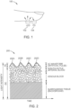
- FIG. 1 illustrates an example technique 100 for using a fingertip sensor to determine a PPG.
- a PPG sensor measures changes in blood volume within a blood vessel using a light emitting diode (LED) 102 and photodetector (PD) 104.
- the LED 102 emits a light of a known wavelength, such as 640 nm (red) or 910 nm (infrared) through the soft tissue.
- the PD 104 detects light that is backscattered or reflected from one or more of the tissue, bone, and/or blood vessels.
- the modulation of reflected light correlates to the volume of blood in the arteries.
- the modulation of reflected light creates a pulsatile waveform indicative of the heart beating.
- a PPG can be used to detect a variety of biometric parameters, including, but not limited to, heart rate as described with reference to FIG. 2 , respiration rate (RR) as described with reference to FIG. 3 , heart rate variability (HRV), respiration rate variability (RRV), peripheral capillary oxygen saturation (SpO2) level, blood pressure, cholesterol, heart disease, blood glucose, stress, and hemoglobin A1C level.
- FIG. 2 illustrates an example PPG waveform 200. Peaks 202A-202D in the waveform 200 correspond to heart beats. Accordingly, a PPG signal is used to determine or monitor the subject's heart beats.
- FIG. 3 illustrates a raw PPG waveform 300A and a filtered PPG waveform 300B used to determine a subject's RR.
- RR is included as low frequency content (e.g., 0.1-0.4 Hz) within the PPG signal.
- a raw PPG signal 300A is bandpass filtered, and the power spectral content is identified, for example, through performing a Fourier Transform on the signal. Peaks, such as peaks 302A and 302B in the resulting filtered PPG signal 300B, indicate the subject's RR.
- the subject's HRV can be determined from the time between peaks in the signal.
- a subject passes through five stages of sleep: wake, N1, N2, N3, and rapid eye movement (REM) sleep.
- the order of each stage and amount of time spent in each stage may differ across subjects.
- a subject repeatedly transitions from wake, N1, N2, N3, N2, perhaps N1, REM, and perhaps N1 in a sleep cycle.
- a sleep cycle may last approximately 90 minutes.
- the subject may spend less time in N3.
- the subject may spend an increased amount of time in N1.
- a subject transitions form wake, to N1, N2, N3, and REM.
- a subject wakes for a brief period of time and returns to the previous sleep stage or a sleep stage one off from the previous sleep stage.
- N1 may be called sleep transition because a subject transitions from being awake to being asleep.
- N2 may be referred to as light sleep.
- N2 is the stage of sleep subjects are in for the majority of the night.
- N3 may be referred to a deep sleep.
- N3 is the stage of sleep most related to body restoration and metabolic function. REM sleep tends to be restorative to the mind and related to memory consolidation.
- a sleep stage can be determined using various physiological biosignals, such as HR, HRV, RR, and RRV.
- HRV is highest when awake, due to sympathetic nervous system dominance and the HRV is lowest during deep sleep due to parasympathetic nervous system dominance.
- FIG. 4 illustrates average HRV values during each sleep stage.
- FIG. 4 illustrates an average HRV for 13 subjects.
- Each arrow tracks a single subject's HRV as a function of sleep stage.
- the dashed line 404 shows the HRV for subject 402 through the sleep stages of one sleep cycle. When awake, the subject's HRV was just greater than 200.
- the HRV for the subject in light sleep (N2) was approximately 125
- the HRV for the subject during deep sleep (N3) was approximately 75
- the HRV for the subject during REM was approximately 90.
- FIG. 5 illustrates that RRV is greatest during wake and REM and decreases during N1, N2, and N3.
- aspects provide methods and apparatus for a non-invasive, continuous, and accurate determination of a subject's sleep stage.
- a PPG sensor configured to measure signals from an ear of a subject wearing an in-ear earpiece.
- At least one processor either internal or external to the in-ear earpiece, has instructions stored in memory that are configured to cause the at least one processor to (1) determine a sleep stage of the subject based, at least in part, on the PPG signals and (2) provide one or more outputs.
- the outputs are provided to a user, user's clinician, or user's physician based on the determined sleep stage.
- the outputs are stored internal or external to the in-ear earpiece, displayed internal or external to the in-ear earpiece, or used externally to the in-ear earpiece.
- the sleep stage is used to change the behavior of the in-ear audio earpiece based on the determined sleep stage.
- the in-ear earpiece may change an audio output based on the determined sleep stage in an effort to protect sleep.
- N1, N2, N3, and REM sleep stages for illustrative purposes; however, the phrase "sleep stage" is not so limited.
- the determined sleep stages include wake, light sleep (N1 or N2), deep sleep (N3), and REM.
- sleep stages include wake, non-REM (N1, N2, or N3), and REM.
- sleep stages include wake and sleep (N1, N2, N3, or REM).
- FIG. 6 illustrates an example of an in-ear earpiece. 600.
- the earpiece 600 includes an earbud 604 that houses an acoustic driver module and is coupled to a body 610, a nozzle 608 extending from a body 610 of the earpiece towards a substantially frusto-conical sealing structure 602 (called an ear tip), and a positioning and retaining structure 606.
- the 610 of the earpiece 600 is substantially elliptical or circular in shape to align with typical ear geometries.
- the body 610 is coupled to the earbud 604.
- the earbud 604 includes an acoustic driver module.
- the earbud 604 includes electronic modules (not shown) for wirelessly communicating with external devices and networks.
- a nozzle 608 extends from the body 610 towards the ear canal of the subject's ear.
- the nozzle includes an acoustic passage to conduct sound waves to the ear canal of the subject.
- the in-ear earpiece provides enough surface area to contact the subject's skin when positioned in-ear.
- the soft, flexible material of the ear tip sealing structure 602 helps the tip to conform to the subject's ear geometry and increases the surface area having contact with a subject's skin. Additionally, the flare of the umbrella-shaped ear tip 602 provides some springiness so that some pressure is exerted by the ear tip 602 on the subject's skin.
- the positioning and retaining structure 606 holds the earpiece in position in a subject's ear, without significant contribution from the portions of the ear tip that engage the ear canal and without any structure external to the ear tip.
- the earpiece 600 includes a positioning and retaining structure 606 having an outer leg and an inner leg; however, the disclosure is not limited to an ear tip having two legs.
- an ear tip includes a single leg extending from the body and configured to follow the curve of the anti-helix and/or the cymba concha at the rear of the concha.
- the earpiece 600 is connected, either via a wired connection or a wireless connection, to a second earpiece configured to fit in subject's right ear.
- the earpiece is part of a wearable form factor, such as audio eyeglasses, headsets, or a sleep mask.
- the in-ear earpiece includes at least one PPG sensor.
- the sensor includes an LED and a PD as shown in FIG. 1 .
- the PPG sensor is disposed on the earbud 604, in a region that contacts the body 610 of the earpiece 600.
- the LED and PD are housed on or inside the nozzle 608 of the earbud. When the sensor is contained within the nozzle, the light from the LED effectively passes through the tip 602 with little or no interference from the tip.
- the LED and PD are disposed on the back side of the umbrella tip, so that the light from the LED shines through the ear tip 602 and into the subject's ear canal. The PD measures the light that is reflected back.
- the ear tip includes multiple emitters and collectors. In an aspect, at least some of the multiple emitters and collectors are positioned on the back side of the umbrella tip. In an example, at least some of the collectors and emitters form a circular or semi-circular shape.
- the PPG sensor contacts the subject's concha or the subject's ear canal. In an aspect, the PPG sensor contacts a region between concha and the ear canal of the subject.
- the PPG sensor is disposed anywhere on the earpiece 600 where the PPG sensor is able to collect an in-ear PPG signal.
- the earpiece 600 includes one or more of a memory and processor, communication unit, transceiver, and audio output transducer or speaker.
- any of the PPG sensor, memory and processor, communication unit, transceiver, and audio output transducer are configured to communicate with each other. In an example, all of these components are coupled to and communicate with each other.
- the memory and processor control the operations of the earpiece 600.
- the memory stores program code for controlling the memory and processor.
- the memory may include Read Only Memory (ROM), a Random Access Memory (RAM), and/or a flash ROM.
- the processor controls the general operation of the earpiece 600.
- the processor performs process and control for audio and/or data communication.
- the processor is configured to determine a subject's PPG, determine a sleep stage, and determine one more outputs based on the determined sleep stage.
- the processor is configured to output the determined PPG, sleep stage, and/or outputs determined based on the sleep stage.
- the processor in combination with one or more other components of the earpiece, perform the operations described herein.
- the communication unit facilitates a wireless connection with one or more other devices.
- the communication unit may include one or more wireless protocol engines such as a Bluetooth engine. While Bluetooth is used as an example protocol, other communication protocols may also be used. Some examples include Bluetooth Low Energy (BLE), Near Field Communications (NFC), IEEE 802.11, or other local area network (LAN) or personal area network (PAN) protocols.
- BLE Bluetooth Low Energy
- NFC Near Field Communications
- PAN personal area network
- the communication unit wirelessly communicates with an external device, such as a bedside unit, a tablet, a cell phone, a smart device, or the cloud.
- an external device such as a bedside unit, a tablet, a cell phone, a smart device, or the cloud.
- the cloud devices in communication with the cloud which may or may not be in direct communication with the earpiece 600 may access the sleep information.
- the communication unit wirelessly communicates an indication of the collected PPG waveform.
- External devices or cloud may determine the subj ect's PPG from the waveform, the subj ect's sleep stage, and one or more outputs based, at least in part, on the subject's sleep stage. Further, determined sleep stages may be stored on the cloud, and displayed via a web site or applications is in direct or indirect communication with the in-ear earpiece.
- the earpiece communicates with an external device through a wired connection.
- the external device receives an indication of the collected PPG waveform from the earpiece through the wired connection, determines the subject's PPG from the waveform, the subj ect's sleep stage, and one or more other outputs based, at least in part, on the subject's sleep stage.
- the external device transmits the sleep stage and other outputs to the earpiece through the wired connection or the external device wirelessly transmits the sleep stage and other outputs to yet another device or network.
- the transceiver transmits and receives information via one or more antennae to exchange information with one or more other devices and/or the cloud.
- the transceiver is not necessarily a distinct component.
- the audio output transducer may be also known as a driver or speaker. In some examples, more than one output transducer is used.
- the transducer converts electrical signals into sound and converts sound into electrical signals. In aspects, the transducer adjusts an audio output by the earpiece 600 based on a determined sleep stage.
- any in-ear earpiece including a PPG sensor is used to determine a subject's sleep stage based on the collected PPG and configured to provide any number of outputs related to the subject's sleep to the subject or other people.
- the in-ear PPG sensor collects a signal used to determine the subject's PPG.
- a processor onboard the in-ear earpiece determines the sleep stage based on the collected PPG signal.
- a transceiver in the in-ear earpiece transmits the measured PPG signal to an external processor, network, or cloud server.
- the external processor, network, or cloud server processes the PPG signal to determine the subject's sleep stage.
- the determined sleep stage is transmitted by the processor, network, or cloud server to the in-ear earpiece or directly to an external device such as any smart device.
- one or both of the in-ear earpiece and processor external to the in-ear earpiece are also configured to determine any number of physiological signals based, at least in part, on the obtained PPG signal.
- physiological signals include HR, HRV, RR, RRV, and blood oxygenation level.
- the sleep stage can be determined based on the PPG signal or the PPG signal and any combination of the estimated physiological signals.
- the in-ear earpiece estimates physiological signals from the collected PPG to determine a sleep stage of the subject.
- the determined sleep stage is transmitted by the in-ear earpiece to another device for output.
- the information regarding estimated physiological signals is also transmitted by the in-ear earpiece to another device for output.
- a processor external to the in-ear earpiece estimates one or more physiological signals from the collected PPG, determines a sleep stage of the subject, and transmits the determined sleep stage to the in-ear earpiece or another device for output.
- Two overarching methods are provided for determining a sleep stage using information obtained from an in-ear PPG sensor.
- a machine learning algorithm is used to determine the sleep stage and provide an output.
- the person may be the subject wearing the in-ear earpiece, a subject's clinician, and/or the subject's physician.
- physiological signals are extracted from the PPG signal and the extracted physiological signals are input into a machine learning model.
- Physiological signals are extracted from the PPG signal using low pass filtering, linear smoothing, and other processing techniques.
- the machine learning algorithm learns a relationship between each one of the physiological signal inputs and the output sleep stage.
- the machine learning algorithm receives ground truth, for example from clinical PSGs, and data collected from the subject's in-ear PPG sensor. Through supervised learning, the algorithm learns relationships between each of the physiological signals obtained from the PPG signal and between the physiological signals and a sleep stage.
- peaks of a PPG signal are identified and a standard deviation of the time between the peaks results in an estimate of the subject's HRV.
- HRV is input into the machine learning algorithm.
- Other features, such as HR and RR, may be also be extracted from the PPG signal and input into the algorithm.
- the machine learning algorithm compares the input features with known relationships to determine a subject's sleep stage at a particular time.
- the raw PPG signal is input into a machine learning algorithm.
- the PPG signal without pre-processing, is input into a neural network.
- the neural network determines the features, relationships between the features, and relationships between one or more of the features and a sleep stage.
- features include any physiological signal or characteristic of the raw PPG waveform, such as amplitude or period of the signal.
- Inputting the raw PPG signal into the model may be computationally intensive relative to inputting features into a machine learning algorithm; however, this technique provides increased flexibility because the model may find new features and associations between features and between features and a sleep stage.
- FIG. 7 illustrates an example of an output 700 generated based on a subject's determined sleep stage.
- the output 700 is displayed on a device in communication with the in-ear earpiece.
- the output is displayed on an application running on the subject's cell phone or tablet.
- the hypnogram displayed in FIG. 7 represents the stages of sleep as a function of time. People may easily understand the amount of time slept in each sleep stage, and therefore how the subject slept in a sleep period, through the visual representation shown in FIG. 7 .
- the hypnogram displays arousal events (brief period of wake) followed by returning to the previous sleep stage, or returning to a sleep stage one off from the previous sleep stage.
- outputs provided to the subject, a clinician, and/or a physician include one or more sleep statistics, suggested behavioral changes, medical diagnosis, and intelligent audio output adjustments based on the sleep stage.
- a method outputting a medical diagnosis does not fall within the scope of the claims.
- the output based on the determined sleep stage includes a sleep latency indicating how long it took the user to fall asleep, how long the user slept in a given sleep period, the number of times the user woke up in a given period of time, and/or a sleep score that summarizes the quality of the user's sleep over a sleep period.
- the sleep score includes any combination of outputs described herein. Any combination of these outputs are displayed on an application running on the subject's cell phone or tablet.
- Sleep statistics include information such as how long it took a subject to fall asleep, the time the subject fell asleep, and the time the subject woke up in one sleep period.
- a sleep score that indicates the subject's overall sleep quality is output.
- suggested behavioral changes include a virtual sleep coach running on an application in communication with the in-ear earpiece suggesting behavioral modifications based on the subject's prior monitored sleep.
- the sleep coach suggests that the subject go to sleep earlier based on how the subject slept the night before.
- the sleep coach encourages the subject to decrease caffeine or alcohol consumption based on how the subject slept the night before.
- the output provides an indication encouraging the subject to seek medical attention because of unhealthy sleeping patterns, abnormal sleeping, or based on observed symptoms associated with a medical condition such as insomnia or sleep apnea.
- a method including the output providing an indication of a medical condition such as insomnia or sleep apnea does not fall into the scope of the claims.
- the in-ear earpiece intelligently transitions between different stimuli. Initially, a first stimulus is output by the in-ear earpiece to help guide the subject to fall asleep. When the subject is determined to be asleep, the in-ear earpiece transitions from outputting the first stimulus to outputting a second stimulus that protects the subject's sleep. In another example, the in-ear earpiece adjusts a level of noise masking when the subject is determined to be asleep.
- an in-ear earpiece including a PPG sensor configured to measure signals from a wearer, determine a sleep stage of the subject based on the PPG, and provide an output based on the determined sleep stage.
- the methods for monitoring the subject's sleep described herein eliminate the need for a sleep lab setting and clinician scoring the subject's sleep. Due to the form factor, a subject's sleep is continuously monitored in a non-invasive manner. Using a machine learning algorithm to determine a sleep stage and other outputs provides consistent sleep scoring across multiple people and multiple sleep sessions.
- aspects of the present disclosure may take the form of an entirely hardware embodiment, an entirely software embodiment (including firmware, resident software, micro-code, etc.) or an embodiment combining software and hardware aspects that may all generally be referred to herein as a "component,” “circuit,” “module” or “system.”
- aspects of the present disclosure may take the form of a computer program product embodied in one or more computer readable medium(s) having computer readable program code embodied thereon.
- the computer readable medium may be a computer readable signal medium or a computer readable storage medium.
- a computer readable storage medium may be, for example, but not limited to, an electronic, magnetic, optical, electromagnetic, infrared, or semiconductor system, apparatus, or device, or any suitable combination of the foregoing.
- a computer readable storage medium include: an electrical connection having one or more wires, a hard disk, a random access memory (RAM), a read-only memory (ROM), an erasable programmable read-only memory (EPROM or Flash memory), an optical fiber, a portable compact disc read-only memory (CD-ROM), an optical storage device, a magnetic storage device, or any suitable combination of the foregoing.
- a computer readable storage medium may be any tangible medium that can contain or store a program.
- each block in the flowchart or block diagrams may represent a module, segment or portion of code, which comprises one or more executable instructions for implementing the specified logical function(s).
- the functions noted in the block may occur out of the order noted in the figures.
- two blocks shown in succession may, in fact, be executed substantially concurrently, or the blocks may sometimes be executed in the reverse order, depending upon the functionality involved.
- Each block of the block diagrams and/or flowchart illustrations, and combinations of blocks in the block diagrams and/or flowchart illustrations can be implemented by special-purpose hardware-based systems that perform the specified functions or acts, or combinations of special purpose hardware and computer instructions.
Description
- Aspects of the present disclosure relate to continuous and accurate determination of a subj ect's sleep stage based, at least in part, on a photoplethysmogram (PPG) of a subject determined using a PPG sensor positioned on an in-ear audio device. As described herein, one or more outputs are determined based on the sleep stage.
- Sleep disturbances influence human health. A sleep study or sleep evaluation includes a number of tests performed at the same time while a subject is sleeping. The tests measure specific sleep characteristics to gain a better understanding of the subject's sleep and help to diagnose sleep disorders. Typically, the tests are performed in a sleep lab setting.
- Polysomnography (PSG) is the gold standard for sleep evaluation. PSG measures the electrical activity of a subject's brain (electroencephalography, (EEG)), using an electrode cap. PSG also monitors electrooculogram (EOG), electrocardiogram (ECG, EKG), airflow respiratory effort, pulse oximetry, leg or arm EMG, and other biosignals. Once data is collected, a sleep technician scores individual 30-second epochs of the data to determine a corresponding sleep stage and values for one or more other biometric parameters. The scored data, viewed in combination with the subject's medical history, is used to diagnose, or rule out, types of sleep disorders. While PSG and other sleep study methods are informative, there is a need for non-invasively and continuously determining a subject's sleep stage. Ideally, sleep may be monitored in the comfort of the subject's home using minimal equipment. Relevant prior art documents with respect to the present patent application are
US 2016/029898 A1 ,EP 3 377 963 A1 - The present invention is limited by the appended claims.
- According to aspects, an in-ear audio device is configured to determine, estimate, or calculate a subject's PPG using at least one sensor disposed on the audio device. The subject's sleep stage is determined based on the PPG. In aspects, one or more other physiological signals are measured, estimated, or calculated using the PPG signal. In an example, the sleep stage and other outputs associated with the subject's sleep are provided to the subject, the subject's physician, and/or the subject's clinician. In an example, the sleep stage is used by the in-ear audio device to change the behavior of the audio device based on the determined sleep stage.
- Aspects provide a system comprising a PPG sensor disposed on an in-ear earpiece, the PPG sensor configured to measure signals from an ear of a subject wearing the in-ear earpiece and instructions, stored in a memory, that cause at least one processor to: determine a sleep stage of the subject based, at least in part, on the signals and provide an output based on the determined sleep stage.
- In an aspect, the instructions cause at least one processor to determine the sleep stage by: transmitting, by a transceiver of the in-ear earpiece, the measured signals to a processor external to the in-ear earpiece and receiving, by the transceiver of the in-ear earpiece, the determined sleep stage from the processor external to the in-ear earpiece.
- In an aspect, the processor external to the in-ear earpiece has instructions stored in a memory that cause the processor external to the in-ear earpiece to estimate one or more physiological signals based on the measured signals, and determine the sleep stage of the subject based, at least in part, the one or more physiological signals.
- In an aspect, the one or more physiological signals comprise one of: heart rate (HR), heart rate variability (HRV), respiration rate (RR), respiration rate variability (RRV) or blood oxygenation level.
- In an aspect, the processor external to the in-ear earpiece has instructions stored in the memory that further cause the processor external to the in-ear earpiece to: transmit the determined sleep stage to the in-ear earpiece.
- In an aspect, the instructions cause the processor external to the in-ear earpiece to determine the sleep stage of the subject by: estimating the sleep stage using a machine learning algorithm. In an aspect, the instructions cause the processor external to the in-ear earpiece to estimate one or more physiological signals by: estimating the one or more physiological signals using a machine learning algorithm.
- In an aspect, the instructions cause the at least one processor to provide the output based on the determined sleep stage by: outputting, via an application running on a wireless device in communication with the in-ear earpiece, a hypnogram illustrating the determined sleep stage as a function of time for a given sleep period.
- In an aspect, the sleep stage comprises one of: wake, N1, N2, N3, and rapid eye movement (REM) sleep stages.
- In an aspect, the signals are measured from one of the concha, the ear canal, or a region between the concha and the ear canal of the subject.
- Aspects provide a method for determining a sleep stage of a subject comprising: measuring signals collected using a PPG sensor disposed on an in-ear earpiece, determining the sleep stage of the subject based, at least in part, on the measured signals, and providing an output based on the determined sleep stage.
- In an aspect, determining the sleep stage comprises: transmitting, by an in-ear ear piece, the measured signals to a processor external to the in-ear earpiece and receiving, by the in-ear earpiece, the determined sleep stage from the processor.
- In an aspect, the method further comprises estimating, by the processor, one or more physiological signals based on the measured signals and determining, by the processor, the sleep stage of the subject based, at least in part, the one or more physiological signals.
- In an aspect, the one or more physiological signals comprise one of: heart rate (HR), heart rate variability (HRV), respiration rate (RR), respiration rate variability (RRV) or blood oxygenation level.
- In an aspect, the method further comprises transmitting, by the processor, the determined sleep stage to the in-ear earpiece. In an aspect, determining the sleep stage of the subject comprises estimating the sleep stage using a machine learning algorithm. In an aspect, estimating the one or more physiological signals comprises estimating the one or more physiological signals using a machine learning algorithm.
- In an aspect, wherein providing the output based on the determined sleep stage comprises outputting, via an application running on a wireless device in communication with the in-ear earpiece, a hypnogram illustrating the determined sleep stage as a function of time for a given sleep period.
- Aspects provide an in-ear earpiece comprising: a PPG sensor configured to measure signals from a subject wearing the earpiece and instructions, stored in a memory, that cause at least one processor to: determine a sleep stage of the subject based, at least in part, on the signals and provide an output based on the determined sleep stage to the subject. In an aspect, the sleep stage is determined based on one or more physiological signals estimated using the measured signals.
- Two or more features described in this disclosure, including those described in this summary section, can be combined to form implementations not specifically described herein. The details of one or more aspects are set forth in the accompanying drawings and the description below. Other features, objects, and advantages will be apparent from the description, drawings, and the claims.
-
-
FIG. 1 illustrates an example technique for using a fingertip sensor to determine a PPG. -
FIG. 2 illustrates an example PPG waveform. -
FIG. 3 illustrates raw and bandpass filtered PPG waveforms correlating to a respiration waveform. -
FIG. 4 illustrates heart rate variability (HRV) as a function of sleep stage. -
FIG. 5 illustrates respiration rate variability (RRV) as a function of sleep stage. -
FIG. 6 illustrates an example in-ear earpiece. -
FIG. 7 illustrates an example output determined based, at least in part, on the PPG signal collected using a PPG sensor disposed on an in-ear earpiece. - PPG sensors optically detect changes in the blood flow volume (i.e., changes in the detected light intensity) in the microvascular bed of tissue. PPG is detected via reflection from or transmission through the tissue. PPG sensors can be used to estimate a variety of biometric parameters. Fingertip and earlobe measures are currently used; however, these locations may have limited blood perfusion. In addition, conventional fingertip or earlobe PPG sensors may not be ideal for taking measurements over a long period of time, such as during a sleep period.
-
FIG. 1 illustrates anexample technique 100 for using a fingertip sensor to determine a PPG. A PPG sensor measures changes in blood volume within a blood vessel using a light emitting diode (LED) 102 and photodetector (PD) 104. In an example, theLED 102 emits a light of a known wavelength, such as 640 nm (red) or 910 nm (infrared) through the soft tissue. ThePD 104 detects light that is backscattered or reflected from one or more of the tissue, bone, and/or blood vessels. The modulation of reflected light correlates to the volume of blood in the arteries. The modulation of reflected light creates a pulsatile waveform indicative of the heart beating. - A PPG can be used to detect a variety of biometric parameters, including, but not limited to, heart rate as described with reference to
FIG. 2 , respiration rate (RR) as described with reference toFIG. 3 , heart rate variability (HRV), respiration rate variability (RRV), peripheral capillary oxygen saturation (SpO2) level, blood pressure, cholesterol, heart disease, blood glucose, stress, and hemoglobin A1C level. -
FIG. 2 illustrates anexample PPG waveform 200.Peaks 202A-202D in thewaveform 200 correspond to heart beats. Accordingly, a PPG signal is used to determine or monitor the subject's heart beats. -
FIG. 3 illustrates araw PPG waveform 300A and a filteredPPG waveform 300B used to determine a subject's RR. RR is included as low frequency content (e.g., 0.1-0.4 Hz) within the PPG signal. To extract a subject's RR, araw PPG signal 300A is bandpass filtered, and the power spectral content is identified, for example, through performing a Fourier Transform on the signal. Peaks, such aspeaks PPG signal 300B, indicate the subject's RR. The subject's HRV can be determined from the time between peaks in the signal. - Typically, a subject passes through five stages of sleep: wake, N1, N2, N3, and rapid eye movement (REM) sleep. The order of each stage and amount of time spent in each stage may differ across subjects. In an example, a subject repeatedly transitions from wake, N1, N2, N3, N2, perhaps N1, REM, and perhaps N1 in a sleep cycle. A sleep cycle may last approximately 90 minutes. In subsequent sleep cycles of a sleep period, the subject may spend less time in N3. In the last few sleep cycles of a sleep period, the subject may spend an increased amount of time in N1. In another example, a subject transitions form wake, to N1, N2, N3, and REM. In yet another example, a subject wakes for a brief period of time and returns to the previous sleep stage or a sleep stage one off from the previous sleep stage.
- N1 may be called sleep transition because a subject transitions from being awake to being asleep. N2 may be referred to as light sleep. N2 is the stage of sleep subjects are in for the majority of the night. N3 may be referred to a deep sleep. N3 is the stage of sleep most related to body restoration and metabolic function. REM sleep tends to be restorative to the mind and related to memory consolidation.
- Research has shown that a sleep stage can be determined using various physiological biosignals, such as HR, HRV, RR, and RRV. For example, HRV is highest when awake, due to sympathetic nervous system dominance and the HRV is lowest during deep sleep due to parasympathetic nervous system dominance.
-
FIG. 4 illustrates average HRV values during each sleep stage. At 400,FIG. 4 illustrates an average HRV for 13 subjects. Each arrow tracks a single subject's HRV as a function of sleep stage. The dashed line 404 shows the HRV for subject 402 through the sleep stages of one sleep cycle. When awake, the subject's HRV was just greater than 200. The HRV for the subject in light sleep (N2) was approximately 125, the HRV for the subject during deep sleep (N3) was approximately 75, and the HRV for the subject during REM was approximately 90. - Similar to HRV, other biometrics trend as a function of sleep stage. HR and RR can both be used to determine between awake versus asleep (rather than specific sleep stages). Each of HR and RR tend to decrease as a subject drifts from awake to asleep. Respiration rate variability (RRV), similar to HRV, shows more definitive trends in relation to sleep stages. At 500,
FIG. 5 illustrates that RRV is greatest during wake and REM and decreases during N1, N2, and N3. - Various biometrics, including those described above, can be estimated or determined using a PPG sensor. Further, the estimated or determined biometrics indicate a sleep stage and provide useful information about the subject's sleep. In view of the shortcomings of traditional sleep studies, aspects provide methods and apparatus for a non-invasive, continuous, and accurate determination of a subject's sleep stage. Specifically, aspects provide a PPG sensor configured to measure signals from an ear of a subject wearing an in-ear earpiece. At least one processor, either internal or external to the in-ear earpiece, has instructions stored in memory that are configured to cause the at least one processor to (1) determine a sleep stage of the subject based, at least in part, on the PPG signals and (2) provide one or more outputs. In an example, the outputs are provided to a user, user's clinician, or user's physician based on the determined sleep stage. In an aspect, the outputs are stored internal or external to the in-ear earpiece, displayed internal or external to the in-ear earpiece, or used externally to the in-ear earpiece. Additionally or alternatively, the sleep stage is used to change the behavior of the in-ear audio earpiece based on the determined sleep stage. For example, the in-ear earpiece may change an audio output based on the determined sleep stage in an effort to protect sleep.
- Aspects describe N1, N2, N3, and REM as sleep stages for illustrative purposes; however, the phrase "sleep stage" is not so limited. In an aspect, the determined sleep stages include wake, light sleep (N1 or N2), deep sleep (N3), and REM. In yet other aspects, sleep stages include wake, non-REM (N1, N2, or N3), and REM. In other aspects, sleep stages include wake and sleep (N1, N2, N3, or REM).
-
FIG. 6 illustrates an example of an in-ear earpiece. 600. Theearpiece 600 includes anearbud 604 that houses an acoustic driver module and is coupled to abody 610, anozzle 608 extending from abody 610 of the earpiece towards a substantially frusto-conical sealing structure 602 (called an ear tip), and a positioning and retainingstructure 606. - The 610 of the
earpiece 600 is substantially elliptical or circular in shape to align with typical ear geometries. In an example, thebody 610 is coupled to theearbud 604. In aspects, theearbud 604 includes an acoustic driver module. In an example, theearbud 604 includes electronic modules (not shown) for wirelessly communicating with external devices and networks. - A
nozzle 608 extends from thebody 610 towards the ear canal of the subject's ear. The nozzle includes an acoustic passage to conduct sound waves to the ear canal of the subject. - The in-ear earpiece provides enough surface area to contact the subject's skin when positioned in-ear. The soft, flexible material of the ear
tip sealing structure 602 helps the tip to conform to the subject's ear geometry and increases the surface area having contact with a subject's skin. Additionally, the flare of the umbrella-shapedear tip 602 provides some springiness so that some pressure is exerted by theear tip 602 on the subject's skin. - The positioning and retaining
structure 606 holds the earpiece in position in a subject's ear, without significant contribution from the portions of the ear tip that engage the ear canal and without any structure external to the ear tip. In an example, as shown inFIG. 6 , theearpiece 600 includes a positioning and retainingstructure 606 having an outer leg and an inner leg; however, the disclosure is not limited to an ear tip having two legs. In an example, an ear tip includes a single leg extending from the body and configured to follow the curve of the anti-helix and/or the cymba concha at the rear of the concha. - In aspects, the
earpiece 600 is connected, either via a wired connection or a wireless connection, to a second earpiece configured to fit in subject's right ear. In aspects, the earpiece is part of a wearable form factor, such as audio eyeglasses, headsets, or a sleep mask. - The in-ear earpiece includes at least one PPG sensor. In one aspect, the sensor includes an LED and a PD as shown in
FIG. 1 . In an example, the PPG sensor is disposed on theearbud 604, in a region that contacts thebody 610 of theearpiece 600. In an example, the LED and PD are housed on or inside thenozzle 608 of the earbud. When the sensor is contained within the nozzle, the light from the LED effectively passes through thetip 602 with little or no interference from the tip. In another example, the LED and PD are disposed on the back side of the umbrella tip, so that the light from the LED shines through theear tip 602 and into the subject's ear canal. The PD measures the light that is reflected back. In another aspect, the ear tip includes multiple emitters and collectors. In an aspect, at least some of the multiple emitters and collectors are positioned on the back side of the umbrella tip. In an example, at least some of the collectors and emitters form a circular or semi-circular shape. In aspects, the PPG sensor contacts the subject's concha or the subject's ear canal. In an aspect, the PPG sensor contacts a region between concha and the ear canal of the subject. - Generally, the PPG sensor is disposed anywhere on the
earpiece 600 where the PPG sensor is able to collect an in-ear PPG signal. - In addition to the PPG sensor, in aspects, the
earpiece 600 includes one or more of a memory and processor, communication unit, transceiver, and audio output transducer or speaker. In an aspect, any of the PPG sensor, memory and processor, communication unit, transceiver, and audio output transducer are configured to communicate with each other. In an example, all of these components are coupled to and communicate with each other. - The memory and processor control the operations of the
earpiece 600. The memory stores program code for controlling the memory and processor. The memory may include Read Only Memory (ROM), a Random Access Memory (RAM), and/or a flash ROM. The processor controls the general operation of theearpiece 600. The processor performs process and control for audio and/or data communication. In some aspects, in addition to the general operation, the processor is configured to determine a subject's PPG, determine a sleep stage, and determine one more outputs based on the determined sleep stage. In aspects, the processor is configured to output the determined PPG, sleep stage, and/or outputs determined based on the sleep stage. In an example, the processor, in combination with one or more other components of the earpiece, perform the operations described herein. - The communication unit facilitates a wireless connection with one or more other devices. For example, the communication unit may include one or more wireless protocol engines such as a Bluetooth engine. While Bluetooth is used as an example protocol, other communication protocols may also be used. Some examples include Bluetooth Low Energy (BLE), Near Field Communications (NFC), IEEE 802.11, or other local area network (LAN) or personal area network (PAN) protocols.
- In an example, the communication unit wirelessly communicates with an external device, such as a bedside unit, a tablet, a cell phone, a smart device, or the cloud. By communicating with the cloud, devices in communication with the cloud which may or may not be in direct communication with the
earpiece 600 may access the sleep information. - In an example, the communication unit wirelessly communicates an indication of the collected PPG waveform. External devices or cloud may determine the subj ect's PPG from the waveform, the subj ect's sleep stage, and one or more outputs based, at least in part, on the subject's sleep stage. Further, determined sleep stages may be stored on the cloud, and displayed via a web site or applications is in direct or indirect communication with the in-ear earpiece.
- In an aspects, the earpiece communicates with an external device through a wired connection. The external device receives an indication of the collected PPG waveform from the earpiece through the wired connection, determines the subject's PPG from the waveform, the subj ect's sleep stage, and one or more other outputs based, at least in part, on the subject's sleep stage. The external device transmits the sleep stage and other outputs to the earpiece through the wired connection or the external device wirelessly transmits the sleep stage and other outputs to yet another device or network.
- The transceiver transmits and receives information via one or more antennae to exchange information with one or more other devices and/or the cloud. The transceiver is not necessarily a distinct component. The audio output transducer may be also known as a driver or speaker. In some examples, more than one output transducer is used. The transducer converts electrical signals into sound and converts sound into electrical signals. In aspects, the transducer adjusts an audio output by the
earpiece 600 based on a determined sleep stage. - The
earpiece 600 is provided for illustrative purposes only. Aspects of the disclosure are not limited to the specific form factor illustrated inFIG. 6 or described with reference toFIG. 6 . According to aspects, any in-ear earpiece including a PPG sensor is used to determine a subject's sleep stage based on the collected PPG and configured to provide any number of outputs related to the subject's sleep to the subject or other people. - As described above, the in-ear PPG sensor collects a signal used to determine the subject's PPG. In an example, a processor onboard the in-ear earpiece determines the sleep stage based on the collected PPG signal.
- In another example, a transceiver in the in-ear earpiece transmits the measured PPG signal to an external processor, network, or cloud server. The external processor, network, or cloud server processes the PPG signal to determine the subject's sleep stage. The determined sleep stage is transmitted by the processor, network, or cloud server to the in-ear earpiece or directly to an external device such as any smart device.
- Regardless of where the PPG signal is processed, one or both of the in-ear earpiece and processor external to the in-ear earpiece are also configured to determine any number of physiological signals based, at least in part, on the obtained PPG signal. Non-limiting examples of physiological signals include HR, HRV, RR, RRV, and blood oxygenation level. The sleep stage can be determined based on the PPG signal or the PPG signal and any combination of the estimated physiological signals.
- In one example, the in-ear earpiece estimates physiological signals from the collected PPG to determine a sleep stage of the subject. The determined sleep stage is transmitted by the in-ear earpiece to another device for output. In aspects, the information regarding estimated physiological signals is also transmitted by the in-ear earpiece to another device for output. In another example, a processor external to the in-ear earpiece estimates one or more physiological signals from the collected PPG, determines a sleep stage of the subject, and transmits the determined sleep stage to the in-ear earpiece or another device for output.
- Two overarching methods are provided for determining a sleep stage using information obtained from an in-ear PPG sensor. In both methods, a machine learning algorithm is used to determine the sleep stage and provide an output. The person may be the subject wearing the in-ear earpiece, a subject's clinician, and/or the subject's physician.
- According to a first technique, physiological signals are extracted from the PPG signal and the extracted physiological signals are input into a machine learning model. Physiological signals are extracted from the PPG signal using low pass filtering, linear smoothing, and other processing techniques. Through supervised learning, the machine learning algorithm learns a relationship between each one of the physiological signal inputs and the output sleep stage.
- The machine learning algorithm receives ground truth, for example from clinical PSGs, and data collected from the subject's in-ear PPG sensor. Through supervised learning, the algorithm learns relationships between each of the physiological signals obtained from the PPG signal and between the physiological signals and a sleep stage.
- In one example, peaks of a PPG signal are identified and a standard deviation of the time between the peaks results in an estimate of the subject's HRV. HRV is input into the machine learning algorithm. Other features, such as HR and RR, may be also be extracted from the PPG signal and input into the algorithm. The machine learning algorithm compares the input features with known relationships to determine a subject's sleep stage at a particular time.
- According to a second technique, the raw PPG signal is input into a machine learning algorithm. In an example, the PPG signal, without pre-processing, is input into a neural network. The neural network determines the features, relationships between the features, and relationships between one or more of the features and a sleep stage. Examples of features include any physiological signal or characteristic of the raw PPG waveform, such as amplitude or period of the signal. Inputting the raw PPG signal into the model may be computationally intensive relative to inputting features into a machine learning algorithm; however, this technique provides increased flexibility because the model may find new features and associations between features and between features and a sleep stage.
-
FIG. 7 illustrates an example of anoutput 700 generated based on a subject's determined sleep stage. Theoutput 700 is displayed on a device in communication with the in-ear earpiece. In one example, the output is displayed on an application running on the subject's cell phone or tablet. The hypnogram displayed inFIG. 7 represents the stages of sleep as a function of time. People may easily understand the amount of time slept in each sleep stage, and therefore how the subject slept in a sleep period, through the visual representation shown inFIG. 7 . In aspects, the hypnogram displays arousal events (brief period of wake) followed by returning to the previous sleep stage, or returning to a sleep stage one off from the previous sleep stage. - In addition to outputting a sleep stage, outputs provided to the subject, a clinician, and/or a physician include one or more sleep statistics, suggested behavioral changes, medical diagnosis, and intelligent audio output adjustments based on the sleep stage. A method outputting a medical diagnosis does not fall within the scope of the claims.
- In aspects, the output based on the determined sleep stage includes a sleep latency indicating how long it took the user to fall asleep, how long the user slept in a given sleep period, the number of times the user woke up in a given period of time, and/or a sleep score that summarizes the quality of the user's sleep over a sleep period. In an example, the sleep score includes any combination of outputs described herein. Any combination of these outputs are displayed on an application running on the subject's cell phone or tablet.
- Sleep statistics include information such as how long it took a subject to fall asleep, the time the subject fell asleep, and the time the subject woke up in one sleep period. In an aspect, a sleep score that indicates the subject's overall sleep quality is output.
- According to aspects, suggested behavioral changes include a virtual sleep coach running on an application in communication with the in-ear earpiece suggesting behavioral modifications based on the subject's prior monitored sleep. In an example, the sleep coach suggests that the subject go to sleep earlier based on how the subject slept the night before. In another example, the sleep coach encourages the subject to decrease caffeine or alcohol consumption based on how the subject slept the night before.
- According to aspects, the output provides an indication encouraging the subject to seek medical attention because of unhealthy sleeping patterns, abnormal sleeping, or based on observed symptoms associated with a medical condition such as insomnia or sleep apnea. A method including the output providing an indication of a medical condition such as insomnia or sleep apnea does not fall into the scope of the claims.
- According to aspects, based on the determined sleep stage, the in-ear earpiece intelligently transitions between different stimuli. Initially, a first stimulus is output by the in-ear earpiece to help guide the subject to fall asleep. When the subject is determined to be asleep, the in-ear earpiece transitions from outputting the first stimulus to outputting a second stimulus that protects the subject's sleep. In another example, the in-ear earpiece adjusts a level of noise masking when the subject is determined to be asleep.
- Aspects describe an in-ear earpiece including a PPG sensor configured to measure signals from a wearer, determine a sleep stage of the subject based on the PPG, and provide an output based on the determined sleep stage. The methods for monitoring the subject's sleep described herein eliminate the need for a sleep lab setting and clinician scoring the subject's sleep. Due to the form factor, a subject's sleep is continuously monitored in a non-invasive manner. Using a machine learning algorithm to determine a sleep stage and other outputs provides consistent sleep scoring across multiple people and multiple sleep sessions.
- In the preceding, reference is made to aspects presented in this disclosure.
- The scope of the invention is limited by scope of the appended claims.
- Aspects of the present disclosure may take the form of an entirely hardware embodiment, an entirely software embodiment (including firmware, resident software, micro-code, etc.) or an embodiment combining software and hardware aspects that may all generally be referred to herein as a "component," "circuit," "module" or "system." Furthermore, aspects of the present disclosure may take the form of a computer program product embodied in one or more computer readable medium(s) having computer readable program code embodied thereon.
- Any combination of one or more computer readable medium(s) may be utilized. The computer readable medium may be a computer readable signal medium or a computer readable storage medium. A computer readable storage medium may be, for example, but not limited to, an electronic, magnetic, optical, electromagnetic, infrared, or semiconductor system, apparatus, or device, or any suitable combination of the foregoing. More specific examples of a computer readable storage medium include: an electrical connection having one or more wires, a hard disk, a random access memory (RAM), a read-only memory (ROM), an erasable programmable read-only memory (EPROM or Flash memory), an optical fiber, a portable compact disc read-only memory (CD-ROM), an optical storage device, a magnetic storage device, or any suitable combination of the foregoing. In the current context, a computer readable storage medium may be any tangible medium that can contain or store a program.
- The flowchart and block diagrams in the Figures illustrate the architecture, functionality and operation of possible implementations of systems, methods and computer program products according to various aspects. In this regard, each block in the flowchart or block diagrams may represent a module, segment or portion of code, which comprises one or more executable instructions for implementing the specified logical function(s). In some implementations, the functions noted in the block may occur out of the order noted in the figures. For example, two blocks shown in succession may, in fact, be executed substantially concurrently, or the blocks may sometimes be executed in the reverse order, depending upon the functionality involved. Each block of the block diagrams and/or flowchart illustrations, and combinations of blocks in the block diagrams and/or flowchart illustrations can be implemented by special-purpose hardware-based systems that perform the specified functions or acts, or combinations of special purpose hardware and computer instructions.
Claims (15)
- A system comprising:a photoplethysmogram, PPG, sensor disposed on an in-ear earpiece (600), the PPG sensor configured to measure signals from an ear of a subject wearing the in-ear earpiece (600), wherein the in-ear earpiece comprises: an earbud (604) housing an acoustic driver module, a body (610) substantially elliptical or circular in shape and coupled to the earbud, a positioning and retaining structure (606) and a nozzle (608) extending from the body towards a substantially frusto-conical sealing structure (602), the nozzle extending toward an ear canal of the subject and including an acoustic passage to conduct sound waves to the ear canal of the subject, wherein a light emitting diode, LED, and a photodetector, PD, included in the PPG sensor are housed on or inside the nozzle; andat least one processor;instructions, stored in a memory, that cause the at least one processor to:determine a sleep stage of the subject based, at least in part, on the signals; andprovide an output based on the determined sleep stage.
- The system of claim 1, wherein the instructions cause the at least one processor to determine the sleep stage by:transmitting, by a transceiver of the in-ear earpiece, the measured signals to a processor external to the in-ear earpiece; andreceiving, by the transceiver of the in-ear earpiece, the determined sleep stage from the processor external to the in-ear earpiece.
- The system of claim 2, wherein the processor external to the in-ear earpiece has instructions stored in a memory that cause the processor external to the in-ear earpiece to:estimate one or more physiological signals based on the measured signals; anddetermine the sleep stage of the subject based, at least in part, the one or more physiological signals.
- The system of claim 3, wherein the one or more physiological signals comprise one of: heart rate, HR, heart rate variability, HRV, respiration rate, RR, respiration rate variability, RRV, or blood oxygenation level.
- The system of claim 3, wherein the processor external to the in-ear earpiece has instructions stored in the memory that further cause the processor external to the in-ear earpiece to:
transmit the determined sleep stage to the in-ear earpiece. - The system of claim 3, wherein the instructions cause the processor external to the in-ear earpiece to determine the sleep stage of the subject by:
estimating the sleep stage using a machine-learning algorithm. - The system of claim 1, wherein the instructions cause the at least one processor to provide the output based on the determined sleep stage by:
outputting, via an application running on a wireless device in communication with the in-ear earpiece, a hypnogram illustrating the determined sleep stage as a function of time for a given sleep period. - The system of claim 1, wherein the sleep stage comprises one of: wake, N1, N2, N3, and rapid eye movement, REM, sleep stages.
- The system of claim 1, wherein the PPG sensor is disposed on the in-ear earpiece so that the signals are measured from one of: the ear canal, or a region between the concha and the ear canal of the subject.
- The system of claim 1, wherein the in-ear earpiece is arranged for changing an audio output based on the determined sleep stage so as to protect sleep.
- A method for determining a sleep stage of a subject comprising:measuring signals collected using a photoplethysmogram, PPG, sensor disposed on an in-ear earpiece (600), wherein the in-ear earpiece comprises: an earbud (604) housing an acoustic driver module, a body (610) substantially elliptical or circular in shape and coupled to the earbud, a positioning and retaining structure (606) and a nozzle (608) extending from the body towards a substantially frusto-conical sealing structure (602), the nozzle extending toward an ear canal of the subject and including an acoustic passage to conduct sound waves to the ear canal of the subject, wherein a light emitting diode, LED, and a photodetector, PD, included in the PPG sensor are housed on or inside the nozzle;determining the sleep stage of the subject based, at least in part, on the measured signals; andproviding an output based on the determined sleep stage.
- The method of claim 11, wherein determining the sleep stage comprises:transmitting, by the in-ear earpiece, the measured signals to a processor external to the in-ear earpiece; andreceiving, by the in-ear earpiece, the determined sleep stage from the processor.
- The method of claim 11, wherein providing the output based on the determined sleep stage comprises:
outputting, via an application running on a wireless device in communication with the in-ear earpiece, a hypnogram illustrating the determined sleep stage as a function of time for a given sleep period. - The system of claim 1, wherein the positioning and retaining structure is configured to hold the earpiece in position in the subject's ear, without significant contribution from the portions of the sealing structure that engage the ear canal and without any structure external to the sealing structure.
- The system of claim 1, wherein the in-ear earpiece comprises the PPG sensor and the at least one processor.
Priority Applications (1)
| Application Number | Priority Date | Filing Date | Title |
|---|---|---|---|
| EP23214413.9A EP4356822A2 (en) | 2019-06-19 | 2020-06-18 | Sleep staging using an in-ear photoplethysmography (ppg) |
Applications Claiming Priority (2)
| Application Number | Priority Date | Filing Date | Title |
|---|---|---|---|
| US16/445,464 US10827972B1 (en) | 2019-06-19 | 2019-06-19 | Sleep staging using an in-ear photoplethysmography (PPG) |
| PCT/US2020/038309 WO2020257372A1 (en) | 2019-06-19 | 2020-06-18 | Sleep staging using an in-ear photoplethysmography (ppg) |
Related Child Applications (1)
| Application Number | Title | Priority Date | Filing Date |
|---|---|---|---|
| EP23214413.9A Division EP4356822A2 (en) | 2019-06-19 | 2020-06-18 | Sleep staging using an in-ear photoplethysmography (ppg) |
Publications (2)
| Publication Number | Publication Date |
|---|---|
| EP3986265A1 EP3986265A1 (en) | 2022-04-27 |
| EP3986265B1 true EP3986265B1 (en) | 2023-12-06 |
Family
ID=71465478
Family Applications (2)
| Application Number | Title | Priority Date | Filing Date |
|---|---|---|---|
| EP23214413.9A Pending EP4356822A2 (en) | 2019-06-19 | 2020-06-18 | Sleep staging using an in-ear photoplethysmography (ppg) |
| EP20736882.0A Active EP3986265B1 (en) | 2019-06-19 | 2020-06-18 | Sleep staging using an in-ear photoplethysmography (ppg) |
Family Applications Before (1)
| Application Number | Title | Priority Date | Filing Date |
|---|---|---|---|
| EP23214413.9A Pending EP4356822A2 (en) | 2019-06-19 | 2020-06-18 | Sleep staging using an in-ear photoplethysmography (ppg) |
Country Status (3)
| Country | Link |
|---|---|
| US (1) | US10827972B1 (en) |
| EP (2) | EP4356822A2 (en) |
| WO (1) | WO2020257372A1 (en) |
Families Citing this family (2)
| Publication number | Priority date | Publication date | Assignee | Title |
|---|---|---|---|---|
| CN113080864B (en) * | 2021-04-07 | 2022-02-01 | 电子科技大学 | Common sleep disease detection method through automatic sleep staging results |
| WO2023105246A1 (en) * | 2021-12-12 | 2023-06-15 | Earswitch Ltd | An apparatus and method for capturing biometric data from a human or other animal |
Citations (1)
| Publication number | Priority date | Publication date | Assignee | Title |
|---|---|---|---|---|
| EP3377963B1 (en) * | 2016-01-26 | 2019-12-11 | Samsung Electronics Co., Ltd. | Electronic device and control method thereof |
Family Cites Families (7)
| Publication number | Priority date | Publication date | Assignee | Title |
|---|---|---|---|---|
| US7690378B1 (en) | 2004-07-21 | 2010-04-06 | Pacesetter, Inc. | Methods, systems and devices for monitoring respiratory disorders |
| US9538921B2 (en) * | 2014-07-30 | 2017-01-10 | Valencell, Inc. | Physiological monitoring devices with adjustable signal analysis and interrogation power and monitoring methods using same |
| US9808185B2 (en) * | 2014-09-23 | 2017-11-07 | Fitbit, Inc. | Movement measure generation in a wearable electronic device |
| GB2532745B (en) * | 2014-11-25 | 2017-11-22 | Inova Design Solution Ltd | Portable physiology monitor |
| US9642538B2 (en) * | 2015-07-19 | 2017-05-09 | Sanmina Corporation | System and method for a biosensor monitoring and tracking band |
| WO2017070463A1 (en) * | 2015-10-23 | 2017-04-27 | Valencell, Inc. | Physiological monitoring devices and methods that identify subject activity type |
| EP3378380A1 (en) | 2017-03-22 | 2018-09-26 | Koninklijke Philips N.V. | Sleep stage classification system |
-
2019
- 2019-06-19 US US16/445,464 patent/US10827972B1/en active Active
-
2020
- 2020-06-18 EP EP23214413.9A patent/EP4356822A2/en active Pending
- 2020-06-18 WO PCT/US2020/038309 patent/WO2020257372A1/en unknown
- 2020-06-18 EP EP20736882.0A patent/EP3986265B1/en active Active
Patent Citations (1)
| Publication number | Priority date | Publication date | Assignee | Title |
|---|---|---|---|---|
| EP3377963B1 (en) * | 2016-01-26 | 2019-12-11 | Samsung Electronics Co., Ltd. | Electronic device and control method thereof |
Also Published As
| Publication number | Publication date |
|---|---|
| WO2020257372A1 (en) | 2020-12-24 |
| US10827972B1 (en) | 2020-11-10 |
| EP4356822A2 (en) | 2024-04-24 |
| EP3986265A1 (en) | 2022-04-27 |
Similar Documents
| Publication | Publication Date | Title |
|---|---|---|
| US11357445B2 (en) | Systems and methods for determining sleep patterns and circadian rhythms | |
| EP3117767B1 (en) | Processing biological data | |
| CN212521748U (en) | Sleep physiological system | |
| EP3267880B1 (en) | Portable electronic device to process a signal acquired from a living body and method thereof | |
| US20180014741A1 (en) | Wearable physiological monitoring device | |
| US20110288424A1 (en) | Human fatigue assessment device and human fatigue assessment method | |
| US20220087609A1 (en) | In-ear biometric monitoring using photoplethysmography (ppg) | |
| US20220313098A1 (en) | Wearable biometric waveform analysis systems and methods | |
| JP2017506920A (en) | System and method for enhancing sleep wave removal activity based on cardiac or respiratory characteristics | |
| EP3986265B1 (en) | Sleep staging using an in-ear photoplethysmography (ppg) | |
| TW202041194A (en) | Sleep physiological system capable of evaluating and alleviating the snoring and sleep apnea | |
| US20220218293A1 (en) | Sleep physiological system and sleep alarm method | |
| CN110192846B (en) | Wearable device | |
| JP7109443B2 (en) | patient monitoring | |
| CN114246549A (en) | Electronic device and computer-readable storage medium for detecting apnea | |
| US20200353203A1 (en) | Wearable Therapeutic Intervention Device for Sleep Disorders and Methods of Use Thereof | |
| Cheng et al. | An intelligent sleep quality detection system based on wearable device | |
| US20240000396A1 (en) | Sleep physiological system and sleep alarm method | |
| CN210408404U (en) | Dynamic sphygmomanometer | |
| EP4322838A1 (en) | Systems and methods for multivariate stroke detection |
Legal Events
| Date | Code | Title | Description |
|---|---|---|---|
| STAA | Information on the status of an ep patent application or granted ep patent |
Free format text: STATUS: UNKNOWN |
|
| STAA | Information on the status of an ep patent application or granted ep patent |
Free format text: STATUS: THE INTERNATIONAL PUBLICATION HAS BEEN MADE |
|
| PUAI | Public reference made under article 153(3) epc to a published international application that has entered the european phase |
Free format text: ORIGINAL CODE: 0009012 |
|
| STAA | Information on the status of an ep patent application or granted ep patent |
Free format text: STATUS: REQUEST FOR EXAMINATION WAS MADE |
|
| 17P | Request for examination filed |
Effective date: 20220110 |
|
| AK | Designated contracting states |
Kind code of ref document: A1 Designated state(s): AL AT BE BG CH CY CZ DE DK EE ES FI FR GB GR HR HU IE IS IT LI LT LU LV MC MK MT NL NO PL PT RO RS SE SI SK SM TR |
|
| DAV | Request for validation of the european patent (deleted) | ||
| DAX | Request for extension of the european patent (deleted) | ||
| STAA | Information on the status of an ep patent application or granted ep patent |
Free format text: STATUS: EXAMINATION IS IN PROGRESS |
|
| 17Q | First examination report despatched |
Effective date: 20221207 |
|
| GRAP | Despatch of communication of intention to grant a patent |
Free format text: ORIGINAL CODE: EPIDOSNIGR1 |
|
| STAA | Information on the status of an ep patent application or granted ep patent |
Free format text: STATUS: GRANT OF PATENT IS INTENDED |
|
| INTG | Intention to grant announced |
Effective date: 20230628 |
|
| RAP1 | Party data changed (applicant data changed or rights of an application transferred) |
Owner name: DROWSY DIGITAL, INC. |
|
| GRAS | Grant fee paid |
Free format text: ORIGINAL CODE: EPIDOSNIGR3 |
|
| GRAA | (expected) grant |
Free format text: ORIGINAL CODE: 0009210 |
|
| STAA | Information on the status of an ep patent application or granted ep patent |
Free format text: STATUS: THE PATENT HAS BEEN GRANTED |
|
| AK | Designated contracting states |
Kind code of ref document: B1 Designated state(s): AL AT BE BG CH CY CZ DE DK EE ES FI FR GB GR HR HU IE IS IT LI LT LU LV MC MK MT NL NO PL PT RO RS SE SI SK SM TR |
|
| REG | Reference to a national code |
Ref country code: GB Ref legal event code: FG4D |
|
| REG | Reference to a national code |
Ref country code: CH Ref legal event code: EP |
|
| REG | Reference to a national code |
Ref country code: DE Ref legal event code: R096 Ref document number: 602020022308 Country of ref document: DE |
|
| REG | Reference to a national code |
Ref country code: IE Ref legal event code: FG4D |
|
| P01 | Opt-out of the competence of the unified patent court (upc) registered |
Effective date: 20231206 |
|
| REG | Reference to a national code |
Ref country code: LT Ref legal event code: MG9D |
|
| PG25 | Lapsed in a contracting state [announced via postgrant information from national office to epo] |
Ref country code: GR Free format text: LAPSE BECAUSE OF FAILURE TO SUBMIT A TRANSLATION OF THE DESCRIPTION OR TO PAY THE FEE WITHIN THE PRESCRIBED TIME-LIMIT Effective date: 20240307 |