EP3986192B1 - Protective helmet - Google Patents
Protective helmet Download PDFInfo
- Publication number
- EP3986192B1 EP3986192B1 EP20732603.4A EP20732603A EP3986192B1 EP 3986192 B1 EP3986192 B1 EP 3986192B1 EP 20732603 A EP20732603 A EP 20732603A EP 3986192 B1 EP3986192 B1 EP 3986192B1
- Authority
- EP
- European Patent Office
- Prior art keywords
- liner
- protective helmet
- impact absorbing
- elastic joint
- connecting means
- Prior art date
- Legal status (The legal status is an assumption and is not a legal conclusion. Google has not performed a legal analysis and makes no representation as to the accuracy of the status listed.)
- Active
Links
Images


Classifications
-
- A—HUMAN NECESSITIES
- A42—HEADWEAR
- A42B—HATS; HEAD COVERINGS
- A42B3/00—Helmets; Helmet covers ; Other protective head coverings
- A42B3/04—Parts, details or accessories of helmets
- A42B3/06—Impact-absorbing shells, e.g. of crash helmets
- A42B3/062—Impact-absorbing shells, e.g. of crash helmets with reinforcing means
- A42B3/063—Impact-absorbing shells, e.g. of crash helmets with reinforcing means using layered structures
- A42B3/064—Impact-absorbing shells, e.g. of crash helmets with reinforcing means using layered structures with relative movement between layers
-
- A—HUMAN NECESSITIES
- A42—HEADWEAR
- A42B—HATS; HEAD COVERINGS
- A42B3/00—Helmets; Helmet covers ; Other protective head coverings
- A42B3/04—Parts, details or accessories of helmets
- A42B3/10—Linings
-
- A—HUMAN NECESSITIES
- A42—HEADWEAR
- A42B—HATS; HEAD COVERINGS
- A42B3/00—Helmets; Helmet covers ; Other protective head coverings
- A42B3/04—Parts, details or accessories of helmets
- A42B3/10—Linings
- A42B3/12—Cushioning devices
- A42B3/125—Cushioning devices with a padded structure, e.g. foam
- A42B3/127—Cushioning devices with a padded structure, e.g. foam with removable or adjustable pads
Definitions
- the present invention relates to a protective helmet.
- the present invention refers, even if in a non-exclusive way, to a protective helmet suitable for being used in motor sports, like motocross.
- the helmets which are used during sporting activities generally utilize a construction based on three primary components: an outer shell, an impact absorbing liner and a comfort liner.
- the outer shell made of a rigid material, for example a thermoplastic polymer, like polycarbonate or a fiber-reinforced polymer, has the function to protect the head of the helmet's wearer against impacts with the ground or other objects.
- a thermoplastic polymer like polycarbonate or a fiber-reinforced polymer
- the outer shell is also suitable for dissipating, at least partially, in case of an accident, the impact forces acting on the helmet by spreading and transferring them to the second component of the helmet, the impact absorbing liner.
- the impact absorbing liner is positioned inside and adjacent to the outer shell and it is dome shaped so as to correspond to the shape of the wearer's head.
- the function of the impact absorbing liner is to absorb the impact forces which are generated during an accident, thereby preserving the wearer's head.
- the impact absorbing liner is made of relatively rigid material, like expanded polystyrene.
- the third component is the comfort liner which resides on the surface of the impact absorbing liner facing the wearer's head.
- the comfort liner is usually made of a combination of soft foam and fabric materials and has the function to make comfortable the helmet, by avoiding that the wearer's head gets in direct contact with the relatively rigid impact absorbing liner.
- Linear acceleration might cause skull fracture, epidural hematoma and translational acceleration of the brain, while rotational acceleration might cause the brain to rotate within the skull. Rotation of the brain might result in injuries, like concussion, diffuse axonal injury (DAI), subdural hematoma, contusion and hematoma intracerebral.
- DAI diffuse axonal injury
- the various parts of the helmet may be configured to slide relative to each other.
- This kind of helmet is, for example, disclosed in WO2001/045526 , wherein a protective helmet has an outer shell displaceable relative to the inner shell by means of at least one sliding layer arranged between the outer shell and the inner shell.
- the outer shell and the inner shell are interconnected by means of connecting members, for absorbing energy when a displacement of the outer shell on the inner shell occurs. In this way, impact energy from an oblique impact against the helmet may be absorbed during displacement between the outer shell and the inner shell.
- Connectors suitable for allowing mutual sliding between a first part and a second part of a helmet and for assuring a stable connection between said first part and said second part of the helmet during the normal use are disclosed, for example, in WO2017157765 .
- This connector comprises: a sliding plate; an anchor point on one side of the plate, configured to be connected to the first part; and a deformable material, configured to at least partially cover the side of the plate on which the anchor point is located; wherein a peripheral region of the deformable material is configured to be connected to the second part and an inner region of the deformable material is connected to at least one of the plate and the anchor point.
- the connector further comprises a layer of material that is located on the opposite side of the plate from the anchor point; wherein a low friction interface is provided between the opposing surfaces of the plate and the layer of material.
- the connectors disclosed in WO2017157765 may be effective if they are able to freely slide relative to the low friction interface positioned beneath the plate.
- the connectors are compressed between the deformable material, covering the top portion of the plate, and the low friction interface, covering the bottom portion of the plate, so as to reduce the freedom of movement of the connectors, thereby affecting the possibility that the liner of the helmet might slide, in case of an impact, with respect to the adjacent parts of the helmet.
- US 2016/113346 discloses a protective helmet comprising an outer shell, an impact absorbing liner and a comfort liner.
- the comfort liner is attached to the impact absorbing liner by means of at least one elastic joint.
- the object of the present invention is to provide a protective helmet which solves at least partly the above mentioned problems and drawbacks.
- an aim of the present invention is to provide a protective helmet having a comfort liner which is firmly affixed to the outer shell or to the impact absorbing liner of the helmet during normal use and suitable for being displaced with respect to the outer shell or to the impact absorbing liner during an impact, so as to reduce rotational accelerations acting on the wearer's head.
- an aim of the present invention is to provide a protective helmet having a comfort liner which can be easily attached to and detached from the outer shell or to/from the impact absorbing liner without affecting its functionality.
- an aim of the present invention is to provide a protective helmet which can offer an improved protection against radial and oblique impacts.
- an aim of the present invention is to provide a protective helmet which can be manufactured at competitive costs.
- a protective helmet according to the invention is indicated as a whole by the reference 10.
- Said protective helmet 10 is suitable for being used by motorcyclists, in particular by motocross riders. Nevertheless, as it will appear more clearly from the following description, the protective helmet 10 can also be advantageously used by cyclists, skiers and hockey, football, polo or other sports players where an effective protection of the user's head must be obtained.
- the protective helmet 10 comprises an outer shell 12, which is preferably made of rigid material, for example thermoplastic polymer, like polycarbonate or a fiber-reinforced polymer.
- the outer shell 12 is dome shaped so as to fit over the user's head.
- the helmet might also comprise a visor 14, made preferably of rigid material, which is generally designed to be removably coupled to the outer shell 12.
- the visor 14 may be coupled to the outer shell 12 so as to project above a front opening 16 of the outer shell 12.
- a protective helmet 10 provided with a chin guard 18 is shown.
- the teachings of the present invention may also be advantageously applied to the so-called "jet helmets”.
- the protective helmet 10 also comprises an impact absorbing liner 20 and a comfort liner 22, both arranged inside the outer shell 12.
- the impact absorbing liner 20 is positioned adjacent to the outer shell 12 and it is shaped so as to correspond to the shape of the wearer's head.
- the impact absorbing liner 20 is designed to absorb the energy of impact and it can be made of foam material, like for example expanded polystyrene (EPS) or expanded polypropylene (EPP).
- EPS expanded polystyrene
- EPP expanded polypropylene
- the comfort liner 22 is positioned at the inner surface of the impact absorbing liner 20, so as to be in contact with the wearer's head, during the use of the helmet 10.
- the comfort liner 22 can be made with synthetic foam, for example polyurethane foam pad, covered with a skin-friendly fabric.
- the comfort liner 22 is attached to the outer shell 12 and/or to the impact absorbing liner 20 by means of at least one connecting means 24.
- the comfort liner 22 is removably attached to the outer shell 12 and/or to the impact absorbing liner 20.
- the comfort liner 22 is removably attached to the impact absorbing liner 20.
- the comfort liner may be attached to the outer shell 12 or may be attached both to the outer shell 12 and to the impact absorbing liner 20.
- a first portion of the comfort liner 22 may be attached to the outer shell 12 and a second portion of the comfort liner 22 may be attached to the impact absorbing liner 20.
- the comfort liner 22 is provided with at least one elastic joint 26 which is positioned in proximity of a connecting means 24 for joining said at least one connecting means 24 to the comfort liner 22.
- an elastic joint is a joint which, upon application of an elongating force, is able to be stretched, at least partially, to a biased length which is greater than its original unbiased length, and which will be able to return to its original length upon release of the elongating force.
- an elastic joint may be a joint which, upon application of a compressing force, is able to be contracted, at least partially, to a compressed length which is smaller than its original unbiased length, and which will be able to return to its original length upon release of the compressing force.
- the provision of the elastic joint 26 significantly improves the absorption of rotational acceleration acting on the helmet 10 in case of an oblique impact, reducing the potential risk of injury for the wearer.
- the positioning of the elastic joint 26 between the outer shell 12 or the impact absorbing liner 20 and the comfort liner 22 allows a mutual displacement, in case of an oblique impact, between the outer shell 12 and the comfort liner 22. Since the comfort liner 22 in use is substantially integral with the wearer's head, the rotational energy transmitted to the brain caused by oblique impacts is thus reduced.
- the joint 26 being elastic is also able to dampen such a rotational energy.
- the elastic joint 26 does not affect the fixing of the comfort liner 22 to the outer shell 12 or to the impact absorbing liner 20, allowing the proper fit of the helmet 10 over the user head during normal use. In this way, accidental movements of the helmet 10 on the wearer's head are avoided.
- the provision of the elastic joint 26 allows the comfort liner 22 to stay in the proper position during normal use, while allowing it to displace with respect to the outer shell 12 or to the impact absorbing liner 20 in case of an oblique impact.
- the elastic joint 26 can be a woven or non-woven fabric.
- a number of different materials can be used for the elastic joint 26, for example polyamide, polyurethane or a mixing of polyamide and polyurethane.
- the elastic joint 26 can be a spring, made with a metallic or polymeric material.
- the elastic joint 26 can also be made with elastic rubber tapes.
- the elastic joint 26 can also be made by using a technique which is well-known in the field of garment for motorcyclists, namely by superimposing and joining a layer of thin elastic fabric to a layer of leather. A series of closely arranged transverse stitches are performed when the layer of elastic fabric is fully tensioned with the result that a plurality of folds are created when the suit is in rest condition.
- the inserts so obtained are identified in the technical jargon as "accordion leather stretch inserts".
- the elastic joint 26 can be made with a layer of elastic material having a thickness from 0.1 mm to 1.2 mm, but other thickness values can be used depending on the selected material.
- the comfort liner 22 is dome shaped so as to fit over the user's head.
- the comfort liner 22 may comprise a crown pad 23, designed to encompass the side parts of the user's head, and a top pad 25, designed to be positioned on top of the user's head.
- Crown pad 23 and top pad 25 may be made of a single piece or alternatively they may consist of a number of component parts connected by means of ties. Suitable openings 39 may be provided in the crown pad 23 and/or in the top pad 25 to favor the ventilation of the user's head.
- the elastic joint 26 may be positioned at the bottom portion of the comfort liner 22.
- the elastic joint may be positioned at the bottom portion of the crown pad 23.
- the elastic joint 26 may be positioned at the front bottom portion and/or at rear bottom portion of the crown pad 23.
- the front portion of the crown pad is the portion of the crown pad 23 closer to the front of the user and the rear portion of the crown pad 23 is the portion of the crown pad closer to the neck of the user.
- the elastic joint 26 may be a strip of elastic material running along the bottom portion of the comfort liner 22 so as to form an appendix.
- the elastic joint 26 may consist in one or more elastic bands extending from the bottom edge of the comfort liner 22.
- the connecting means 24 may be directly or indirectly connected to the elastic joint 26.
- the connecting means 24 may be directly applied on the elastic joint 26.
- the comfort liner 22 comprises a supporting flap 28, 29 connected to the elastic joint 26 and the connecting means 24 are provided on this supporting flap 28, 29.
- the supporting flap 28, 29 is made with a rigid or semi-rigid material.
- the supporting flap 28, 29 may be made with a thermoplastic polymer material, like for example polypropylene (PP), acrylonitrile butadiene styrene (ABS) or polyamide (PA).
- PP polypropylene
- ABS acrylonitrile butadiene styrene
- PA polyamide
- the comfort liner 22 may be provided with a front supporting flap 28 and a rear supporting flap 29 on which front connecting means 24A and rear connecting means 24B are respectively provided.
- the front supporting flap 28 is shaped so as to fit with the shape of the front bottom edge of the impact absorbing liner 20.
- the rear supporting flap 29 is shaped so as to fit with the shape of the rear lower portion of the impact absorbing liner 22, namely the portion of the impact absorbing liner 20 facing the nape of the wearer.
- the front supporting flap 28 may be designed to be inserted inside a slit 30 provided at the bottom edge of the impact absorbing liner 20.
- FIG 6 it is schematically shown how the front supporting flap 28 may be inserted inside the slit 30.
- the insertion direction is indicated by the arrows I.
- the front connecting means 24A are preferably provided on the surface of the front supporting flap 28 designed to be faced with the bottom edge of the impact absorbing liner 20.
- the front connecting means 24A may consist of projections 31 shaped to engage with corresponding cavities 32 provided on the slit 30, so that the coupling between the comfort liner 22 and the impact absorbing liner 20 is obtained by means of a shape coupling between the projections 31 of the front connecting means 24A and the cavities 32 of the slit 30.
- the projections 31 and the cavities 32 may be designed for realizing a snap-fit connection.
- front supporting flap 28 allows an easy attachment of the front portion of the comfort liner to the impact absorbing liner, since by means of a single act it is possible to simultaneously couple all the front connecting means 24A to the bottom edge of the impact absorbing liner.
- the front supporting flap 28 being designed to fit with the bottom edge of the impact absorbing liner allows the front portion of the comfort liner to stay close to the impact absorbing liner assuring a high comfort to the user and an improved stability of the helmet over the user's head.
- the rear supporting flap 29 in turn is designed to abut against the rear lower portion of the impact absorbing liner 22.
- the rear connecting means 24B may be provided on the surface of the rear supporting flap 29 facing the impact absorbing liner 20.
- the opposite surface of the rear supporting flap 29, namely the surface facing the user's nape, may be covered by a cushioning pad 22A (see figures 3-5 and 7 ).
- the rear connecting means 24B may consist of a pin 33 designed to be inserted inside a corresponding seat 34 provided on the impact absorbing liner 20.
- the rear connecting means 24B may consist of a seat designed to be engaged by a corresponding projection provided on the impact absorbing liner 20.
- the provision of the rear supporting flap 29 allows an easy attachment of the rear portion of the comfort liner to the impact absorbing liner.
- the rear supporting flap 29 being designed to fit with the rear part of the impact absorbing liner allows the rear portion of the comfort liner to stay close to the impact absorbing liner assuring a high comfort to the user and an improved stability of the helmet over the user's head.
- FIGS. 1-10 refer to the embodiment of the comfort liner 22 with two elastic joints 26 provided at front part of the comfort liner and at rear part of the comfort liner respectively.
- the elastic joints 26 are in the form of a strip connecting a front supporting flap 28 and a rear supporting flap 29 to the comfort liner 22.
- Front connecting means 24A and rear connecting means 24B are provided on the front supporting flap 28 and on the rear supporting flap 29.
- the elastic joints 26 allow a mutual rotation of the outer shell 12 with respect to the user's head.
- Such a mutual rotation takes place around the Z axis of figure 9 and it substantially consists in a backward rotation of the helmet over the users' head (the backward rotation is indicated by the arrow K).
- the mutual rotation K between the impact absorbing liner 20, which is integral with the outer shell 12, and the comfort liner 22, which is in contact with the user's head causes the stretching of the rear elastic joint 26 which will assume a length L1 greater than the original length L of the joint when it is in its neutral configuration (see figure 7 ).
- the mutual rotation K causes the compression of the front elastic joint 26 which will assume a length H1 shorter than the original length H (see figure 8 ).
- the elongation and the compression of the elastic joints 26, respectively provided at the rear part and at the front part of the comfort liner, permit a controlled displacement of the user's head with respect to the outer shell so as to reduce the rotational accelerations acting on the user's head and, indirectly, on the user's brain.
- the elastic joints 26 allow a mutual rotation of the outer shell 12 with respect to the user's head.
- Such a mutual rotation takes place around the X axis of figure 13 and it substantially consists in a sideward rotation of the helmet over the user's head (the sideward rotation is indicated by the arrow S).
- the mutual rotation S between the impact absorbing liner 20, which is integral with the outer shell 12, and the comfort liner 22, , which is in contact with the user's head, causes the stretching of the portion of the rear elastic joint 26 proximate to the right side of the helmet.
- Said portion of the elastic joint 26 will assume a length L1 greater than the original length L, (see figures 12, 13 and 14 ).
- the stretching of this portion of the elastic joint 26 is not uniform.
- the stretching of this portion of the rear elastic joint 26 decreases as the distance from the right side of the outer shell increases.
- the mutual rotation S causes the compression of the portion of the rear elastic joint 26 proximate to the left side of the helmet.
- Said portion of the elastic joint 26 will assume a length L2 shorter than the original length L (see figure 15 ).
- the compression of this portion of the rear elastic joint 26 is not uniform. As a matter of fact, the compression of this portion of the rear elastic joint 26 decreases as the distance from the outer shell increases.
- the front elastic joint 26 in case of a side impact has a behaviour similar to that of the rear elastic joint above disclosed.
- the elastic joints 26 are effective in allowing a controlled displacement of the user's head with respect to the outer shell so as to reduce the rotational accelerations acting on the user's head and, indirectly, on the user's brain.
- the elastic joints 26 are also effective in case of an impact R+ acting on the right part of the helmet and causing a mutual rotation of the outer shell 12 with respect to the user's head around the Y axis of figure 17 . Such a rotation is indicated by the arrow T in figure 17 .
- the mutual rotation T between the impact absorbing liner 20, which is integral with the outer shell 12, and the comfort liner 22, which is in contact with the user's head causes the compression of the portion of the front elastic joint 26 proximate to the right side of the helmet.
- Such a compression is not uniform since it decreases as the distance from the right side of the outer shell increases.
- the mutual rotation T causes the stretching of the portion of the front elastic joint 26 proximate to the left side of the helmet.
- Such a stretching is not uniform since it decreases as the distance from the right side of the outer shell increases.
- the rear elastic joint 26 in case of a mutual rotation T between the outer shell and the comfort liner has a behaviour similar to that of the front elastic joint above disclosed.
- the stretching and the compression of the elastic joints 26 permits the user's head to rotate in a controlled way with respect to the outer shell so as to reduce the rotational accelerations acting on the user's head and, indirectly, on the user's brain.
- a comparison table is provided reporting the values of the peak linear acceleration (PLA) and the peak rotational acceleration (PRA) measured for different impact points on a helmet comprising a comfort liner which is not provided with the elastic joint 26 above disclosed (hereinafter called stiff configuration) and on a helmet comprising a comfort liner with front and rear elastic joints 26 (hereinafter called elastic configuration).
- PPA peak linear acceleration
- PRA peak rotational acceleration
- the tensile modulus of the elastam is about 0.12 N/mm, while the tensile modulus of the generic fabric is about 7.5 N/mm.
- PLA (g) PRA (rad/s 2 ) stiff elastic diff. % stiff elastic diff. % P+ 134,8 139,8 3,71 4603 3535 -23,19 R+ 160,5 155,6 -3,05 7017 4461 -36,42 P- 142,1 146 2,79 7219 6233 -13,65
- references P+, R+, P- identify the different impact points on the helmet, in particular:
- the insertion of the elastic joint 26 allows to reduce the rotational acceleration caused by oblique impacts.
- the elastic joint 26 does not affect the connection of the comfort liner to the impact absorbing liner during the normal use of the helmet.
- the provision of the elastic joint 26 does not make the comfort liner bulky and it does not hinder the connection of the comfort liner to the impact absorbing liner.
Landscapes
- Helmets And Other Head Coverings (AREA)
- Gyroscopes (AREA)
Description
- The present invention relates to a protective helmet. In particular, the present invention refers, even if in a non-exclusive way, to a protective helmet suitable for being used in motor sports, like motocross.
- As it is well known in the art, the helmets which are used during sporting activities generally utilize a construction based on three primary components: an outer shell, an impact absorbing liner and a comfort liner.
- The outer shell, made of a rigid material, for example a thermoplastic polymer, like polycarbonate or a fiber-reinforced polymer, has the function to protect the head of the helmet's wearer against impacts with the ground or other objects.
- The outer shell is also suitable for dissipating, at least partially, in case of an accident, the impact forces acting on the helmet by spreading and transferring them to the second component of the helmet, the impact absorbing liner.
- The impact absorbing liner is positioned inside and adjacent to the outer shell and it is dome shaped so as to correspond to the shape of the wearer's head.
- The function of the impact absorbing liner is to absorb the impact forces which are generated during an accident, thereby preserving the wearer's head.
- Generally, the impact absorbing liner is made of relatively rigid material, like expanded polystyrene.
- The third component is the comfort liner which resides on the surface of the impact absorbing liner facing the wearer's head.
- The comfort liner is usually made of a combination of soft foam and fabric materials and has the function to make comfortable the helmet, by avoiding that the wearer's head gets in direct contact with the relatively rigid impact absorbing liner.
- Nowadays modern protective helmets must be effective in absorbing both radial and oblique impacts.
- Radial impacts result only in linear acceleration, while oblique impacts result in linear and rotational acceleration.
- Linear acceleration might cause skull fracture, epidural hematoma and translational acceleration of the brain, while rotational acceleration might cause the brain to rotate within the skull. Rotation of the brain might result in injuries, like concussion, diffuse axonal injury (DAI), subdural hematoma, contusion and hematoma intracerebral.
- To reduce the rotational energy transmitted to the brain in case of an oblique impact, the various parts of the helmet may be configured to slide relative to each other. This kind of helmet is, for example, disclosed in
WO2001/045526 , wherein a protective helmet has an outer shell displaceable relative to the inner shell by means of at least one sliding layer arranged between the outer shell and the inner shell. In the edge region of the helmet, the outer shell and the inner shell are interconnected by means of connecting members, for absorbing energy when a displacement of the outer shell on the inner shell occurs. In this way, impact energy from an oblique impact against the helmet may be absorbed during displacement between the outer shell and the inner shell. - At the same time there is the need that the various parts of the helmet remain connected to each other during the normal use.
- Connectors suitable for allowing mutual sliding between a first part and a second part of a helmet and for assuring a stable connection between said first part and said second part of the helmet during the normal use are disclosed, for example, in
WO2017157765 . - This connector comprises: a sliding plate; an anchor point on one side of the plate, configured to be connected to the first part; and a deformable material, configured to at least partially cover the side of the plate on which the anchor point is located; wherein a peripheral region of the deformable material is configured to be connected to the second part and an inner region of the deformable material is connected to at least one of the plate and the anchor point. The connector further comprises a layer of material that is located on the opposite side of the plate from the anchor point; wherein a low friction interface is provided between the opposing surfaces of the plate and the layer of material.
- This solution has some drawbacks.
- First of all, this solution makes the manufacturing of the helmet more complex and, as consequence, more costly.
- The steps for applying the connectors to the liner of the helmet are time consuming. Moreover, since the connectors, once fastened to the impact absorbing liner, are able to slide relative to the liner of the helmet, the latter might undergo some displacement with respect to the outer shell also during the normal use and not only in case of impact. Such an occurrence might affect the comfort and the stability of the helmet on the wearer's head.
- Finally, the connectors disclosed in
WO2017157765 may be effective if they are able to freely slide relative to the low friction interface positioned beneath the plate. - However, during the normal use, the connectors are compressed between the deformable material, covering the top portion of the plate, and the low friction interface, covering the bottom portion of the plate, so as to reduce the freedom of movement of the connectors, thereby affecting the possibility that the liner of the helmet might slide, in case of an impact, with respect to the adjacent parts of the helmet.
-
US 2016/113346 discloses a protective helmet comprising an outer shell, an impact absorbing liner and a comfort liner. The comfort liner is attached to the impact absorbing liner by means of at least one elastic joint. - The object of the present invention is to provide a protective helmet which solves at least partly the above mentioned problems and drawbacks.
- In particular, an aim of the present invention is to provide a protective helmet having a comfort liner which is firmly affixed to the outer shell or to the impact absorbing liner of the helmet during normal use and suitable for being displaced with respect to the outer shell or to the impact absorbing liner during an impact, so as to reduce rotational accelerations acting on the wearer's head.
- Moreover, an aim of the present invention is to provide a protective helmet having a comfort liner which can be easily attached to and detached from the outer shell or to/from the impact absorbing liner without affecting its functionality.
- Furthermore, an aim of the present invention is to provide a protective helmet which can offer an improved protection against radial and oblique impacts.
- Finally an aim of the present invention is to provide a protective helmet which can be manufactured at competitive costs.
- These and other objects and aims are achieved by the protective helmet according to claim 1. The advantages and the characteristic features of the invention will appear more clearly from the following description of a preferred, but not exclusive, embodiment of the protective helmet with reference to the accompanying figures in which:
-
figure 1 shows a side view of a protective helmet according to the present invention; -
figure 2 shows a schematic cross section of the protective helmet offigure 1 , wherein the visor has been removed for sake of clarity; -
figure 3 shows a bottom view of the comfort liner of the protective helmet offigure 1 ; -
figures 4 and5 are, respectively, a front and a rear perspective view of the comfort liner offigure 3 ; -
figure 6 shows schematically how the front portion of the comfort liner offigure 3 might be attached to the impact absorbing liner of the protective helmet offigure 1 ; -
figures 7 and 8 are, respectively, enlarged views of the details A and B offigure 2 ; -
figure 9 is a view similar tofigure 2 , wherein a backward rotation of the protective helmet, with respect to the user's head, is schematically shown; -
figures 10 and 11 are, respectively, enlarged views of the details A1 and B1 offigure 9 ; -
figure 12 schematically shown a cross section view taken along the line XII-XII offigure 2 ; -
figure 13 is a view similar tofigure 12 , wherein a sideward rotation of the protective helmet, with respect to the user's head, is schematically shown; -
figures 14 and 15 are, respectively, enlarged views of the details E and D offigure 13 ; -
figure 16 schematically shown a cross section view taken along the line XVI-XVI offigure 2 ; -
figure 17 is a view similar tofigure 16 , wherein a sideward rotation of the protective helmet, with respect to the user's head, is schematically shown. - With reference to the attached figures, an example of a protective helmet according to the invention is indicated as a whole by the
reference 10. Saidprotective helmet 10 is suitable for being used by motorcyclists, in particular by motocross riders. Nevertheless, as it will appear more clearly from the following description, theprotective helmet 10 can also be advantageously used by cyclists, skiers and hockey, football, polo or other sports players where an effective protection of the user's head must be obtained. - As shown in
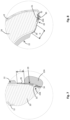
figure 1 , theprotective helmet 10 comprises anouter shell 12, which is preferably made of rigid material, for example thermoplastic polymer, like polycarbonate or a fiber-reinforced polymer. Theouter shell 12 is dome shaped so as to fit over the user's head. The helmet might also comprise avisor 14, made preferably of rigid material, which is generally designed to be removably coupled to theouter shell 12. Thevisor 14 may be coupled to theouter shell 12 so as to project above a front opening 16 of theouter shell 12. Infigure 1 , aprotective helmet 10 provided with achin guard 18 is shown. However, the teachings of the present invention may also be advantageously applied to the so-called "jet helmets". - As shown in
figure 2 , theprotective helmet 10 also comprises animpact absorbing liner 20 and acomfort liner 22, both arranged inside theouter shell 12. - The
impact absorbing liner 20 is positioned adjacent to theouter shell 12 and it is shaped so as to correspond to the shape of the wearer's head. Theimpact absorbing liner 20 is designed to absorb the energy of impact and it can be made of foam material, like for example expanded polystyrene (EPS) or expanded polypropylene (EPP). - The
comfort liner 22 is positioned at the inner surface of theimpact absorbing liner 20, so as to be in contact with the wearer's head, during the use of thehelmet 10. - The
comfort liner 22 can be made with synthetic foam, for example polyurethane foam pad, covered with a skin-friendly fabric. - The
comfort liner 22 is attached to theouter shell 12 and/or to theimpact absorbing liner 20 by means of at least one connectingmeans 24. - Preferably, in order to be cleaned or to be changed with a new one if needed, the
comfort liner 22 is removably attached to theouter shell 12 and/or to theimpact absorbing liner 20. - According to the embodiment of
figure 2 , thecomfort liner 22 is removably attached to theimpact absorbing liner 20. However, in different embodiments, not shown in the attached figures, the comfort liner may be attached to theouter shell 12 or may be attached both to theouter shell 12 and to theimpact absorbing liner 20. For example, a first portion of thecomfort liner 22 may be attached to theouter shell 12 and a second portion of thecomfort liner 22 may be attached to theimpact absorbing liner 20. - If not differently specified, in the following reference will be made to the embodiment of
figure 2 , wherein thecomfort liner 22 is removably attached to theimpact absorbing liner 20. Nonetheless the same notes are also valid for the other above mentioned embodiments. According to the invention, thecomfort liner 22 is provided with at least one elastic joint 26 which is positioned in proximity of a connectingmeans 24 for joining said at least one connecting means 24 to thecomfort liner 22. - In the present specification, the term "elastic" is intended to refer to a material having the property of returning to its original configuration after deformation. In particular, an elastic joint is a joint which, upon application of an elongating force, is able to be stretched, at least partially, to a biased length which is greater than its original unbiased length, and which will be able to return to its original length upon release of the elongating force.
- At the same time an elastic joint may be a joint which, upon application of a compressing force, is able to be contracted, at least partially, to a compressed length which is smaller than its original unbiased length, and which will be able to return to its original length upon release of the compressing force.
- As it will be explained in detail hereinafter, the provision of the elastic joint 26 significantly improves the absorption of rotational acceleration acting on the
helmet 10 in case of an oblique impact, reducing the potential risk of injury for the wearer. As a matter of fact, the positioning of the elastic joint 26 between theouter shell 12 or theimpact absorbing liner 20 and thecomfort liner 22 allows a mutual displacement, in case of an oblique impact, between theouter shell 12 and thecomfort liner 22. Since thecomfort liner 22 in use is substantially integral with the wearer's head, the rotational energy transmitted to the brain caused by oblique impacts is thus reduced. At the same time, the joint 26 being elastic is also able to dampen such a rotational energy. - Moreover, the elastic joint 26 does not affect the fixing of the
comfort liner 22 to theouter shell 12 or to theimpact absorbing liner 20, allowing the proper fit of thehelmet 10 over the user head during normal use. In this way, accidental movements of thehelmet 10 on the wearer's head are avoided. - Consequently, the provision of the elastic joint 26 allows the
comfort liner 22 to stay in the proper position during normal use, while allowing it to displace with respect to theouter shell 12 or to theimpact absorbing liner 20 in case of an oblique impact. - The elastic joint 26 can be a woven or non-woven fabric. A number of different materials can be used for the elastic joint 26, for example polyamide, polyurethane or a mixing of polyamide and polyurethane.
- Alternatively, the elastic joint 26 can be a spring, made with a metallic or polymeric material.
- The elastic joint 26 can also be made with elastic rubber tapes. In addition, the elastic joint 26 can also be made by using a technique which is well-known in the field of garment for motorcyclists, namely by superimposing and joining a layer of thin elastic fabric to a layer of leather. A series of closely arranged transverse stitches are performed when the layer of elastic fabric is fully tensioned with the result that a plurality of folds are created when the suit is in rest condition. The inserts so obtained are identified in the technical jargon as "accordion leather stretch inserts".
- The elastic joint 26 can be made with a layer of elastic material having a thickness from 0.1 mm to 1.2 mm, but other thickness values can be used depending on the selected material.
- As shown in
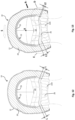
figures 3-5 , thecomfort liner 22 is dome shaped so as to fit over the user's head. Thecomfort liner 22 may comprise acrown pad 23, designed to encompass the side parts of the user's head, and atop pad 25, designed to be positioned on top of the user's head. -
Crown pad 23 andtop pad 25 may be made of a single piece or alternatively they may consist of a number of component parts connected by means of ties.Suitable openings 39 may be provided in thecrown pad 23 and/or in thetop pad 25 to favor the ventilation of the user's head. - According to the embodiments shown in the attached figures, the elastic joint 26 may be positioned at the bottom portion of the
comfort liner 22. - In particular, the elastic joint may be positioned at the bottom portion of the
crown pad 23. According to the embodiment offigures 3-5 , the elastic joint 26 may be positioned at the front bottom portion and/or at rear bottom portion of thecrown pad 23. The front portion of the crown pad is the portion of thecrown pad 23 closer to the front of the user and the rear portion of thecrown pad 23 is the portion of the crown pad closer to the neck of the user. - As shown in the attached figures, the elastic joint 26 may be a strip of elastic material running along the bottom portion of the
comfort liner 22 so as to form an appendix. - In a different embodiment, the elastic joint 26 may consist in one or more elastic bands extending from the bottom edge of the
comfort liner 22. - However different embodiments are possible since, in order to be effective, it is only requested that the elastic joint 26 is interposed between the connecting
means 24 and a peripheral portion of thecomfort liner 22. - The connecting means 24 may be directly or indirectly connected to the elastic joint 26.
- In the first case, not forming part of the claimed invention and not shown in the attached figures, the connecting
means 24 may be directly applied on the elastic joint 26. - In the second case, according to the claimed invention, the
comfort liner 22 comprises a supportingflap means 24 are provided on this supportingflap - The supporting
flap - For example, the supporting
flap figures 3-5 , thecomfort liner 22 may be provided with a front supportingflap 28 and arear supporting flap 29 on which front connecting means 24A and rear connecting means 24B are respectively provided. - Preferably, the front supporting
flap 28 is shaped so as to fit with the shape of the front bottom edge of theimpact absorbing liner 20. Similarly, therear supporting flap 29 is shaped so as to fit with the shape of the rear lower portion of theimpact absorbing liner 22, namely the portion of theimpact absorbing liner 20 facing the nape of the wearer. - With reference to
figures 6 and8 , the front supportingflap 28 may be designed to be inserted inside aslit 30 provided at the bottom edge of theimpact absorbing liner 20. Infigure 6 it is schematically shown how the front supportingflap 28 may be inserted inside theslit 30. The insertion direction is indicated by the arrows I. - The front connecting means 24A are preferably provided on the surface of the front supporting
flap 28 designed to be faced with the bottom edge of theimpact absorbing liner 20. - The front connecting means 24A may consist of
projections 31 shaped to engage with correspondingcavities 32 provided on theslit 30, so that the coupling between thecomfort liner 22 and theimpact absorbing liner 20 is obtained by means of a shape coupling between theprojections 31 of the front connecting means 24A and thecavities 32 of theslit 30. - The
projections 31 and thecavities 32 may be designed for realizing a snap-fit connection. - The provision of the front supporting
flap 28 allows an easy attachment of the front portion of the comfort liner to the impact absorbing liner, since by means of a single act it is possible to simultaneously couple all the front connecting means 24A to the bottom edge of the impact absorbing liner. - At the same time, the front supporting
flap 28 being designed to fit with the bottom edge of the impact absorbing liner allows the front portion of the comfort liner to stay close to the impact absorbing liner assuring a high comfort to the user and an improved stability of the helmet over the user's head. - The
rear supporting flap 29 in turn is designed to abut against the rear lower portion of theimpact absorbing liner 22. The rear connecting means 24B may be provided on the surface of the rear supportingflap 29 facing theimpact absorbing liner 20. The opposite surface of the rear supportingflap 29, namely the surface facing the user's nape, may be covered by acushioning pad 22A (seefigures 3-5 and7 ). - The rear connecting means 24B may consist of a
pin 33 designed to be inserted inside acorresponding seat 34 provided on theimpact absorbing liner 20. - Alternatively, the rear connecting means 24B may consist of a seat designed to be engaged by a corresponding projection provided on the
impact absorbing liner 20. - The provision of the rear supporting
flap 29 allows an easy attachment of the rear portion of the comfort liner to the impact absorbing liner. - At the same time, the
rear supporting flap 29 being designed to fit with the rear part of the impact absorbing liner allows the rear portion of the comfort liner to stay close to the impact absorbing liner assuring a high comfort to the user and an improved stability of the helmet over the user's head. - Hereafter the behaviour of the
protective helmet 10 in case of an impact will be described by specifically referring tofigures 9-17 . - These figures refer to the embodiment of the
comfort liner 22 with twoelastic joints 26 provided at front part of the comfort liner and at rear part of the comfort liner respectively. Theelastic joints 26 are in the form of a strip connecting a front supportingflap 28 and arear supporting flap 29 to thecomfort liner 22. Front connecting means 24A and rear connecting means 24B are provided on the front supportingflap 28 and on therear supporting flap 29. - However, the same comments are also valid for the other embodiments above disclosed.
- In case of an impact at the front part of the protective helmet (see arrow P- in
figure 9 ), theelastic joints 26 allow a mutual rotation of theouter shell 12 with respect to the user's head. Such a mutual rotation takes place around the Z axis offigure 9 and it substantially consists in a backward rotation of the helmet over the users' head (the backward rotation is indicated by the arrow K). - As it is schematically shown in
figures 10 and 11 , the mutual rotation K between theimpact absorbing liner 20, which is integral with theouter shell 12, and thecomfort liner 22, which is in contact with the user's head, causes the stretching of the rear elastic joint 26 which will assume a length L1 greater than the original length L of the joint when it is in its neutral configuration (seefigure 7 ). - At the same time, the mutual rotation K causes the compression of the front elastic joint 26 which will assume a length H1 shorter than the original length H (see
figure 8 ). - The elongation and the compression of the
elastic joints 26, respectively provided at the rear part and at the front part of the comfort liner, permit a controlled displacement of the user's head with respect to the outer shell so as to reduce the rotational accelerations acting on the user's head and, indirectly, on the user's brain. - Also in case of an impact at the left part of the protective helmet (see arrow R- in
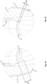
figure 13 ), theelastic joints 26 allow a mutual rotation of theouter shell 12 with respect to the user's head. Such a mutual rotation takes place around the X axis offigure 13 and it substantially consists in a sideward rotation of the helmet over the user's head (the sideward rotation is indicated by the arrow S). - As it is schematically shown in
figures 12 and 13 , the mutual rotation S between theimpact absorbing liner 20, which is integral with theouter shell 12, and thecomfort liner 22, , which is in contact with the user's head, causes the stretching of the portion of the rear elastic joint 26 proximate to the right side of the helmet. Said portion of the elastic joint 26 will assume a length L1 greater than the original length L, (seefigures 12, 13 and14 ). In this case, the stretching of this portion of the elastic joint 26 is not uniform. As a matter of fact, the stretching of this portion of the rear elastic joint 26 decreases as the distance from the right side of the outer shell increases. - At the same time, the mutual rotation S causes the compression of the portion of the rear elastic joint 26 proximate to the left side of the helmet. Said portion of the elastic joint 26 will assume a length L2 shorter than the original length L (see
figure 15 ). - Also in this case, the compression of this portion of the rear elastic joint 26 is not uniform. As a matter of fact, the compression of this portion of the rear elastic joint 26 decreases as the distance from the outer shell increases.
- The front elastic joint 26 in case of a side impact has a behaviour similar to that of the rear elastic joint above disclosed.
- Therefore, also in this case, the
elastic joints 26 are effective in allowing a controlled displacement of the user's head with respect to the outer shell so as to reduce the rotational accelerations acting on the user's head and, indirectly, on the user's brain. - With reference to
figures 16 and 17 , theelastic joints 26 are also effective in case of an impact R+ acting on the right part of the helmet and causing a mutual rotation of theouter shell 12 with respect to the user's head around the Y axis offigure 17 . Such a rotation is indicated by the arrow T infigure 17 . - In this case, the mutual rotation T between the
impact absorbing liner 20, which is integral with theouter shell 12, and thecomfort liner 22, which is in contact with the user's head, causes the compression of the portion of the front elastic joint 26 proximate to the right side of the helmet. Such a compression is not uniform since it decreases as the distance from the right side of the outer shell increases. - At the same time, the mutual rotation T causes the stretching of the portion of the front elastic joint 26 proximate to the left side of the helmet. Such a stretching is not uniform since it decreases as the distance from the right side of the outer shell increases.
- The rear elastic joint 26 in case of a mutual rotation T between the outer shell and the comfort liner has a behaviour similar to that of the front elastic joint above disclosed.
- Also in this case, thus, the stretching and the compression of the
elastic joints 26 permits the user's head to rotate in a controlled way with respect to the outer shell so as to reduce the rotational accelerations acting on the user's head and, indirectly, on the user's brain. - Hereinafter a comparison table is provided reporting the values of the peak linear acceleration (PLA) and the peak rotational acceleration (PRA) measured for different impact points on a helmet comprising a comfort liner which is not provided with the elastic joint 26 above disclosed (hereinafter called stiff configuration) and on a helmet comprising a comfort liner with front and rear elastic joints 26 (hereinafter called elastic configuration).
- The materials used for the elastic configuration and for the stiff configuration are elastam (specifically Lycra®) and a generic fabric respectively.
- A tensile test according to ISO 13594-1 was performed to characterize the above mentioned materials.
- The tensile modulus of the elastam is about 0.12 N/mm, while the tensile modulus of the generic fabric is about 7.5 N/mm.
PLA (g) PRA (rad/s2) stiff elastic diff. % stiff elastic diff. % P+ 134,8 139,8 3,71 4603 3535 -23,19 R+ 160,5 155,6 -3,05 7017 4461 -36,42 P- 142,1 146 2,79 7219 6233 -13,65 - In the above table, the references P+, R+, P-, identify the different impact points on the helmet, in particular:
- P+ identifies an impact on the rear part of the helmet;
- R+ identifies an impact on the right part of the helmet;
- P- identifies an impact on the front part of the helmet.
- From the table it can be observed that the elastic joints do not affect substantially the linear absorption (PLA).
- At the same time the peak values of rotational acceleration of the helmet having the elastic configuration are considerably reduced with respect to the values of rotational acceleration of the helmet having the stiff configuration.
- Obviously the elastam is only one of the various elastic materials which can be used for the elastic joint 26.
- At this point it is clear how the predefined objects are achieved with the
protective helmet 10 according to the invention. - As a matter of fact, the insertion of the elastic joint 26 allows to reduce the rotational acceleration caused by oblique impacts.
- At the same time, the elastic joint 26 does not affect the connection of the comfort liner to the impact absorbing liner during the normal use of the helmet.
- Moreover, the provision of the elastic joint 26 does not make the comfort liner bulky and it does not hinder the connection of the comfort liner to the impact absorbing liner.
- With regard to the embodiments of the
protective helmet 10 described above, the person skilled in the art may, in order to satisfy specific requirements, make modifications to and/or replace elements described with equivalent elements, without thereby departing from the scope of the accompanying claims.
Claims (14)
- A protective helmet (10) comprising:- an outer shell (12);- an impact absorbing liner (20), positioned inside to the outer shell (12) and shaped so as to correspond to the shape of the wearer's head;- a comfort liner (22) positioned at the inner surface of the impact absorbing liner (20), so as to be in contact with the wearer's head; the comfort liner (22) being attached to the outer shell (12) and/or to the impact absorbing liner (20) by means of at least one connecting means (24);wherein the comfort liner (22) is provided with at least one elastic joint (26) which is positioned in proximity of said at least one connecting means (24) for joining the connecting means (24) to the comfort liner characterized by said at least one connecting means (24) being indirectly connected to said at least one elastic joint (26) and the comfort liner (22) comprising a rigid or semi-rigid supporting flap (28, 29) connected to the at least one elastic joint (26), the connecting means (24) being provided on said supporting flap (28, 29);said at least one elastic joint (26) being interposed between said at least one connecting means (24) and a peripheral portion of the comfort liner (22).
- Protective helmet (10) according to claim 1, characterized in that said at least one elastic joint (26) is positioned at the bottom portion of the comfort liner (22).
- Protective helmet (10) according to claim 1, characterized in that the comfort liner (20) comprises a crown pad (23), designed to encompass the side parts of the wearer's head, and a top pad (25), designed to be positioned on top of the wearer's head.
- Protective helmet (10) according to claim 3, characterized in that said at least one elastic joint (26) is positioned at the bottom portion of the crown pad (23); said at least one elastic joint (26) being positioned at a front bottom portion or at a rear bottom portion of the crown pad (23).
- Protective helmet (10) according to claim 1, characterized in that the comfort liner (22) comprises a front supporting flap (28) and a rear supporting flap (29); front connecting means (24A) being provided on the front supporting flap (28) and rear connecting means (24B) being provided on the rear supporting flap (29).
- Protective helmet (10) according to claim 5, characterized in that the front supporting flap (28) is shaped so as to fit with the shape of a front bottom edge of the impact absorbing liner (20).
- Protective helmet (10) according to claim 5, characterized in that the front supporting flap (28) is designed to be inserted inside a slit (30) provided at a bottom edge of the impact absorbing liner (20).
- Protective helmet (10) according to claim 7, characterized in that the front connecting means (24A) consist of projections (31) shaped to engage with corresponding cavities (32) provided on the slit (30).
- Protective helmet (10) according to claim 5, characterized in that the rear supporting flap (29) is shaped so as to fit with the shape of a rear lower portion of the impact absorbing liner (22).
- Protective helmet (10) according to claim 9, characterized in that the rear connecting means (24B) are provided on a surface of the rear supporting flap (29) facing the impact absorbing liner (20).
- Protective helmet (10) according to claim 10, characterized in that said rear connecting means (24B) comprise at least one pin (33) designed to be inserted inside a corresponding seat (34) provided on the impact absorbing liner (20).
- Protective helmet (10) according to claim 1, characterized in that said at least one elastic joint (26) is a woven or non-woven fabric.
- Protective helmet (10) according to claim 1, characterized in that said at least one elastic joint (26) is made with polyamide or polyurethane or a mixing of polyamide and polyurethane.
- Protective helmet (10) according to claim 1, characterized in that said at least one elastic joint (26) is a strip of elastic material running along a bottom portion of the comfort liner (22) so as to form an appendix.
Priority Applications (1)
| Application Number | Priority Date | Filing Date | Title |
|---|---|---|---|
| EP25178412.0A EP4581973A3 (en) | 2019-06-18 | 2020-06-17 | Protective helmet |
Applications Claiming Priority (2)
| Application Number | Priority Date | Filing Date | Title |
|---|---|---|---|
| IT102019000009375A IT201900009375A1 (en) | 2019-06-18 | 2019-06-18 | Protective helmet |
| PCT/EP2020/066692 WO2020254358A1 (en) | 2019-06-18 | 2020-06-17 | Protective helmet |
Related Child Applications (1)
| Application Number | Title | Priority Date | Filing Date |
|---|---|---|---|
| EP25178412.0A Division EP4581973A3 (en) | 2019-06-18 | 2020-06-17 | Protective helmet |
Publications (2)
| Publication Number | Publication Date |
|---|---|
| EP3986192A1 EP3986192A1 (en) | 2022-04-27 |
| EP3986192B1 true EP3986192B1 (en) | 2025-05-28 |
Family
ID=68234190
Family Applications (2)
| Application Number | Title | Priority Date | Filing Date |
|---|---|---|---|
| EP20732603.4A Active EP3986192B1 (en) | 2019-06-18 | 2020-06-17 | Protective helmet |
| EP25178412.0A Pending EP4581973A3 (en) | 2019-06-18 | 2020-06-17 | Protective helmet |
Family Applications After (1)
| Application Number | Title | Priority Date | Filing Date |
|---|---|---|---|
| EP25178412.0A Pending EP4581973A3 (en) | 2019-06-18 | 2020-06-17 | Protective helmet |
Country Status (7)
| Country | Link |
|---|---|
| US (1) | US12329227B2 (en) |
| EP (2) | EP3986192B1 (en) |
| JP (1) | JP7485702B2 (en) |
| CN (1) | CN113993410B (en) |
| ES (1) | ES3034687T3 (en) |
| IT (1) | IT201900009375A1 (en) |
| WO (1) | WO2020254358A1 (en) |
Family Cites Families (13)
| Publication number | Priority date | Publication date | Assignee | Title |
|---|---|---|---|---|
| JP2001064821A (en) * | 1999-08-24 | 2001-03-13 | Moon Craft Kk | Helmet for sports |
| ATE271325T1 (en) | 1999-12-21 | 2004-08-15 | Neuroprevention Scandinavia Ab | SAFETY HELMET |
| JP5232505B2 (en) | 2008-03-06 | 2013-07-10 | 株式会社アライヘルメット | Neck pad mounting structure |
| PT2526799E (en) * | 2011-05-26 | 2014-04-29 | Suomy Internat Pte Ltd | Safety helmet, particularly for motorcycle and/or motor racing, with fastening system for the comfort lining |
| US10306941B2 (en) * | 2011-07-27 | 2019-06-04 | Bauer Hockey, Llc | Sports helmet with rotational impact protection |
| ITTV20120001A1 (en) * | 2012-01-04 | 2013-07-05 | Alpinestars Res Srl | HELMET PROVIDED WITH A PADDING ADJUSTMENT DEVICE |
| FR2994061B1 (en) * | 2012-08-01 | 2015-03-27 | Salomon Sas | PROTECTIVE HELMET FOR SPORTS ACTIVITY |
| SE1351032A1 (en) * | 2013-04-19 | 2014-10-20 | Mips Ab | Connecting arrangements and helmets including such connecting arrangements |
| CA2934368C (en) * | 2013-12-19 | 2023-03-21 | Bauer Hockey Corp. | Helmet for impact protection |
| EP3212021A4 (en) * | 2014-10-28 | 2018-06-20 | Bell Sports Inc. | In-mold rotation helmet |
| WO2017157765A1 (en) | 2016-03-17 | 2017-09-21 | Mips Ab | Helmet, liner for a helmet, comfort padding for a helmet and connector |
| GB201708094D0 (en) * | 2017-05-19 | 2017-07-05 | Mips Ab | Helmet |
| CN108771299A (en) * | 2018-06-22 | 2018-11-09 | 郑州艾莫弗信息技术有限公司 | A kind of multifunctional safety helmet based on technology of wireless sensing network |
-
2019
- 2019-06-18 IT IT102019000009375A patent/IT201900009375A1/en unknown
-
2020
- 2020-06-17 EP EP20732603.4A patent/EP3986192B1/en active Active
- 2020-06-17 ES ES20732603T patent/ES3034687T3/en active Active
- 2020-06-17 CN CN202080044074.9A patent/CN113993410B/en active Active
- 2020-06-17 WO PCT/EP2020/066692 patent/WO2020254358A1/en not_active Ceased
- 2020-06-17 US US17/617,372 patent/US12329227B2/en active Active
- 2020-06-17 JP JP2021576028A patent/JP7485702B2/en active Active
- 2020-06-17 EP EP25178412.0A patent/EP4581973A3/en active Pending
Also Published As
| Publication number | Publication date |
|---|---|
| EP3986192A1 (en) | 2022-04-27 |
| EP4581973A3 (en) | 2025-10-08 |
| BR112021025054A2 (en) | 2022-02-01 |
| US20220248793A1 (en) | 2022-08-11 |
| EP4581973A2 (en) | 2025-07-09 |
| CN113993410B (en) | 2024-05-24 |
| US12329227B2 (en) | 2025-06-17 |
| JP7485702B2 (en) | 2024-05-16 |
| CN113993410A (en) | 2022-01-28 |
| WO2020254358A1 (en) | 2020-12-24 |
| IT201900009375A1 (en) | 2020-12-18 |
| ES3034687T3 (en) | 2025-08-21 |
| JP2022537579A (en) | 2022-08-26 |
Similar Documents
| Publication | Publication Date | Title |
|---|---|---|
| US12408722B2 (en) | Modular liner system for protective helmets | |
| EP2550886B1 (en) | Sports helmet with rotational impact protection | |
| US6438761B1 (en) | Protective headband for heading a ball | |
| TWI730453B (en) | Pad, helmet, method of assembling a pad for mounting to a helmet, and method of manufacturing a helmet | |
| US9872532B2 (en) | Sweat management pad for protective helmets | |
| JP7778884B2 (en) | helmet | |
| CA2942637C (en) | Helmet | |
| WO2020181390A1 (en) | Helmet with padding arrangement | |
| EP3986192B1 (en) | Protective helmet | |
| CA2880069A1 (en) | Sports helmet with rotational impact protection | |
| US12022904B2 (en) | Protective helmet | |
| BR112021025054B1 (en) | PROTECTIVE HELMET | |
| RU2801660C1 (en) | Helmet |
Legal Events
| Date | Code | Title | Description |
|---|---|---|---|
| STAA | Information on the status of an ep patent application or granted ep patent |
Free format text: STATUS: UNKNOWN |
|
| STAA | Information on the status of an ep patent application or granted ep patent |
Free format text: STATUS: THE INTERNATIONAL PUBLICATION HAS BEEN MADE |
|
| PUAI | Public reference made under article 153(3) epc to a published international application that has entered the european phase |
Free format text: ORIGINAL CODE: 0009012 |
|
| STAA | Information on the status of an ep patent application or granted ep patent |
Free format text: STATUS: REQUEST FOR EXAMINATION WAS MADE |
|
| 17P | Request for examination filed |
Effective date: 20211215 |
|
| AK | Designated contracting states |
Kind code of ref document: A1 Designated state(s): AL AT BE BG CH CY CZ DE DK EE ES FI FR GB GR HR HU IE IS IT LI LT LU LV MC MK MT NL NO PL PT RO RS SE SI SK SM TR |
|
| DAV | Request for validation of the european patent (deleted) | ||
| DAX | Request for extension of the european patent (deleted) | ||
| TPAC | Observations filed by third parties |
Free format text: ORIGINAL CODE: EPIDOSNTIPA |
|
| STAA | Information on the status of an ep patent application or granted ep patent |
Free format text: STATUS: EXAMINATION IS IN PROGRESS |
|
| 17Q | First examination report despatched |
Effective date: 20231213 |
|
| GRAP | Despatch of communication of intention to grant a patent |
Free format text: ORIGINAL CODE: EPIDOSNIGR1 |
|
| STAA | Information on the status of an ep patent application or granted ep patent |
Free format text: STATUS: GRANT OF PATENT IS INTENDED |
|
| INTG | Intention to grant announced |
Effective date: 20241220 |
|
| GRAS | Grant fee paid |
Free format text: ORIGINAL CODE: EPIDOSNIGR3 |
|
| GRAA | (expected) grant |
Free format text: ORIGINAL CODE: 0009210 |
|
| STAA | Information on the status of an ep patent application or granted ep patent |
Free format text: STATUS: THE PATENT HAS BEEN GRANTED |
|
| AK | Designated contracting states |
Kind code of ref document: B1 Designated state(s): AL AT BE BG CH CY CZ DE DK EE ES FI FR GB GR HR HU IE IS IT LI LT LU LV MC MK MT NL NO PL PT RO RS SE SI SK SM TR |
|
| REG | Reference to a national code |
Ref country code: GB Ref legal event code: FG4D |
|
| RIN1 | Information on inventor provided before grant (corrected) |
Inventor name: PARISSENTI, ROBERTO Inventor name: MAZZAROLO, GIOVANNI |
|
| REG | Reference to a national code |
Ref country code: CH Ref legal event code: EP |
|
| REG | Reference to a national code |
Ref country code: IE Ref legal event code: FG4D Ref country code: DE Ref legal event code: R096 Ref document number: 602020051999 Country of ref document: DE |
|
| REG | Reference to a national code |
Ref country code: NL Ref legal event code: FP |
|
| P01 | Opt-out of the competence of the unified patent court (upc) registered |
Free format text: CASE NUMBER: APP_25008/2025 Effective date: 20250526 |
|
| PGFP | Annual fee paid to national office [announced via postgrant information from national office to epo] |
Ref country code: DE Payment date: 20250603 Year of fee payment: 6 |
|
| PGFP | Annual fee paid to national office [announced via postgrant information from national office to epo] |
Ref country code: GB Payment date: 20250617 Year of fee payment: 6 |
|
| PGFP | Annual fee paid to national office [announced via postgrant information from national office to epo] |
Ref country code: NL Payment date: 20250618 Year of fee payment: 6 |
|
| PGFP | Annual fee paid to national office [announced via postgrant information from national office to epo] |
Ref country code: FR Payment date: 20250603 Year of fee payment: 6 |
|
| REG | Reference to a national code |
Ref country code: ES Ref legal event code: FG2A Ref document number: 3034687 Country of ref document: ES Kind code of ref document: T3 Effective date: 20250821 |
|
| PG25 | Lapsed in a contracting state [announced via postgrant information from national office to epo] |
Ref country code: FI Free format text: LAPSE BECAUSE OF FAILURE TO SUBMIT A TRANSLATION OF THE DESCRIPTION OR TO PAY THE FEE WITHIN THE PRESCRIBED TIME-LIMIT Effective date: 20250528 |
|
| PGFP | Annual fee paid to national office [announced via postgrant information from national office to epo] |
Ref country code: ES Payment date: 20250701 Year of fee payment: 6 |
|
| REG | Reference to a national code |
Ref country code: LT Ref legal event code: MG9D |
|
| PG25 | Lapsed in a contracting state [announced via postgrant information from national office to epo] |
Ref country code: GR Free format text: LAPSE BECAUSE OF FAILURE TO SUBMIT A TRANSLATION OF THE DESCRIPTION OR TO PAY THE FEE WITHIN THE PRESCRIBED TIME-LIMIT Effective date: 20250829 Ref country code: NO Free format text: LAPSE BECAUSE OF FAILURE TO SUBMIT A TRANSLATION OF THE DESCRIPTION OR TO PAY THE FEE WITHIN THE PRESCRIBED TIME-LIMIT Effective date: 20250828 |
|
| PG25 | Lapsed in a contracting state [announced via postgrant information from national office to epo] |
Ref country code: PL Free format text: LAPSE BECAUSE OF FAILURE TO SUBMIT A TRANSLATION OF THE DESCRIPTION OR TO PAY THE FEE WITHIN THE PRESCRIBED TIME-LIMIT Effective date: 20250528 |
|
| PGFP | Annual fee paid to national office [announced via postgrant information from national office to epo] |
Ref country code: IT Payment date: 20250707 Year of fee payment: 6 |
|
| PG25 | Lapsed in a contracting state [announced via postgrant information from national office to epo] |
Ref country code: BG Free format text: LAPSE BECAUSE OF FAILURE TO SUBMIT A TRANSLATION OF THE DESCRIPTION OR TO PAY THE FEE WITHIN THE PRESCRIBED TIME-LIMIT Effective date: 20250528 |
|
| PG25 | Lapsed in a contracting state [announced via postgrant information from national office to epo] |
Ref country code: HR Free format text: LAPSE BECAUSE OF FAILURE TO SUBMIT A TRANSLATION OF THE DESCRIPTION OR TO PAY THE FEE WITHIN THE PRESCRIBED TIME-LIMIT Effective date: 20250528 |
|
| PG25 | Lapsed in a contracting state [announced via postgrant information from national office to epo] |
Ref country code: RS Free format text: LAPSE BECAUSE OF FAILURE TO SUBMIT A TRANSLATION OF THE DESCRIPTION OR TO PAY THE FEE WITHIN THE PRESCRIBED TIME-LIMIT Effective date: 20250828 |
|
| PG25 | Lapsed in a contracting state [announced via postgrant information from national office to epo] |
Ref country code: IS Free format text: LAPSE BECAUSE OF FAILURE TO SUBMIT A TRANSLATION OF THE DESCRIPTION OR TO PAY THE FEE WITHIN THE PRESCRIBED TIME-LIMIT Effective date: 20250928 |
|
| PG25 | Lapsed in a contracting state [announced via postgrant information from national office to epo] |
Ref country code: LV Free format text: LAPSE BECAUSE OF FAILURE TO SUBMIT A TRANSLATION OF THE DESCRIPTION OR TO PAY THE FEE WITHIN THE PRESCRIBED TIME-LIMIT Effective date: 20250528 |
|
| REG | Reference to a national code |
Ref country code: AT Ref legal event code: MK05 Ref document number: 1798107 Country of ref document: AT Kind code of ref document: T Effective date: 20250528 |
|
| PG25 | Lapsed in a contracting state [announced via postgrant information from national office to epo] |
Ref country code: AT Free format text: LAPSE BECAUSE OF FAILURE TO SUBMIT A TRANSLATION OF THE DESCRIPTION OR TO PAY THE FEE WITHIN THE PRESCRIBED TIME-LIMIT Effective date: 20250528 Ref country code: SM Free format text: LAPSE BECAUSE OF FAILURE TO SUBMIT A TRANSLATION OF THE DESCRIPTION OR TO PAY THE FEE WITHIN THE PRESCRIBED TIME-LIMIT Effective date: 20250528 Ref country code: DK Free format text: LAPSE BECAUSE OF FAILURE TO SUBMIT A TRANSLATION OF THE DESCRIPTION OR TO PAY THE FEE WITHIN THE PRESCRIBED TIME-LIMIT Effective date: 20250528 |
|
| PG25 | Lapsed in a contracting state [announced via postgrant information from national office to epo] |
Ref country code: CZ Free format text: LAPSE BECAUSE OF FAILURE TO SUBMIT A TRANSLATION OF THE DESCRIPTION OR TO PAY THE FEE WITHIN THE PRESCRIBED TIME-LIMIT Effective date: 20250528 |
|
| PG25 | Lapsed in a contracting state [announced via postgrant information from national office to epo] |
Ref country code: EE Free format text: LAPSE BECAUSE OF FAILURE TO SUBMIT A TRANSLATION OF THE DESCRIPTION OR TO PAY THE FEE WITHIN THE PRESCRIBED TIME-LIMIT Effective date: 20250528 |
|
| PG25 | Lapsed in a contracting state [announced via postgrant information from national office to epo] |
Ref country code: SK Free format text: LAPSE BECAUSE OF FAILURE TO SUBMIT A TRANSLATION OF THE DESCRIPTION OR TO PAY THE FEE WITHIN THE PRESCRIBED TIME-LIMIT Effective date: 20250528 |
|
| REG | Reference to a national code |
Ref country code: CH Ref legal event code: H13 Free format text: ST27 STATUS EVENT CODE: U-0-0-H10-H13 (AS PROVIDED BY THE NATIONAL OFFICE) Effective date: 20260127 |
|
| PG25 | Lapsed in a contracting state [announced via postgrant information from national office to epo] |
Ref country code: LU Free format text: LAPSE BECAUSE OF NON-PAYMENT OF DUE FEES Effective date: 20250617 |