EP3986082A1 - User plane gateway updating methods, apparatus, computer-readable storage medium and communications system - Google Patents
User plane gateway updating methods, apparatus, computer-readable storage medium and communications system Download PDFInfo
- Publication number
- EP3986082A1 EP3986082A1 EP21195715.4A EP21195715A EP3986082A1 EP 3986082 A1 EP3986082 A1 EP 3986082A1 EP 21195715 A EP21195715 A EP 21195715A EP 3986082 A1 EP3986082 A1 EP 3986082A1
- Authority
- EP
- European Patent Office
- Prior art keywords
- pdn connection
- plane gateway
- mme
- request message
- message
- Prior art date
- Legal status (The legal status is an assumption and is not a legal conclusion. Google has not performed a legal analysis and makes no representation as to the accuracy of the status listed.)
- Granted
Links
- 238000000034 method Methods 0.000 title claims abstract description 134
- 238000004891 communication Methods 0.000 title claims abstract description 11
- 230000008569 process Effects 0.000 claims description 30
- 230000007420 reactivation Effects 0.000 claims description 10
- 230000004044 response Effects 0.000 claims description 5
- 230000007246 mechanism Effects 0.000 abstract description 15
- 230000005540 biological transmission Effects 0.000 abstract description 7
- 230000011664 signaling Effects 0.000 description 30
- 230000008859 change Effects 0.000 description 27
- 238000010586 diagram Methods 0.000 description 23
- 230000003993 interaction Effects 0.000 description 15
- 238000013507 mapping Methods 0.000 description 14
- 230000006870 function Effects 0.000 description 12
- 238000012545 processing Methods 0.000 description 9
- 230000009471 action Effects 0.000 description 4
- 230000002093 peripheral effect Effects 0.000 description 4
- 239000003381 stabilizer Substances 0.000 description 4
- 230000008878 coupling Effects 0.000 description 3
- 238000010168 coupling process Methods 0.000 description 3
- 238000005859 coupling reaction Methods 0.000 description 3
- 230000008901 benefit Effects 0.000 description 2
- 238000012217 deletion Methods 0.000 description 2
- 230000037430 deletion Effects 0.000 description 2
- 230000000977 initiatory effect Effects 0.000 description 2
- 238000012546 transfer Methods 0.000 description 2
- 230000001960 triggered effect Effects 0.000 description 2
- 238000011161 development Methods 0.000 description 1
- 230000000694 effects Effects 0.000 description 1
- 238000005516 engineering process Methods 0.000 description 1
- 239000002360 explosive Substances 0.000 description 1
- 230000006855 networking Effects 0.000 description 1
- 230000003287 optical effect Effects 0.000 description 1
Images


Classifications
-
- H—ELECTRICITY
- H04—ELECTRIC COMMUNICATION TECHNIQUE
- H04W—WIRELESS COMMUNICATION NETWORKS
- H04W8/00—Network data management
- H04W8/02—Processing of mobility data, e.g. registration information at HLR [Home Location Register] or VLR [Visitor Location Register]; Transfer of mobility data, e.g. between HLR, VLR or external networks
- H04W8/08—Mobility data transfer
-
- H—ELECTRICITY
- H04—ELECTRIC COMMUNICATION TECHNIQUE
- H04W—WIRELESS COMMUNICATION NETWORKS
- H04W76/00—Connection management
- H04W76/10—Connection setup
- H04W76/12—Setup of transport tunnels
-
- H—ELECTRICITY
- H04—ELECTRIC COMMUNICATION TECHNIQUE
- H04W—WIRELESS COMMUNICATION NETWORKS
- H04W36/00—Hand-off or reselection arrangements
- H04W36/0005—Control or signalling for completing the hand-off
- H04W36/0011—Control or signalling for completing the hand-off for data sessions of end-to-end connection
-
- H—ELECTRICITY
- H04—ELECTRIC COMMUNICATION TECHNIQUE
- H04W—WIRELESS COMMUNICATION NETWORKS
- H04W64/00—Locating users or terminals or network equipment for network management purposes, e.g. mobility management
-
- H—ELECTRICITY
- H04—ELECTRIC COMMUNICATION TECHNIQUE
- H04W—WIRELESS COMMUNICATION NETWORKS
- H04W64/00—Locating users or terminals or network equipment for network management purposes, e.g. mobility management
- H04W64/003—Locating users or terminals or network equipment for network management purposes, e.g. mobility management locating network equipment
-
- H—ELECTRICITY
- H04—ELECTRIC COMMUNICATION TECHNIQUE
- H04W—WIRELESS COMMUNICATION NETWORKS
- H04W76/00—Connection management
- H04W76/10—Connection setup
- H04W76/19—Connection re-establishment
-
- H—ELECTRICITY
- H04—ELECTRIC COMMUNICATION TECHNIQUE
- H04W—WIRELESS COMMUNICATION NETWORKS
- H04W88/00—Devices specially adapted for wireless communication networks, e.g. terminals, base stations or access point devices
- H04W88/16—Gateway arrangements
Definitions
- the present invention relates to the field of communications technologies, and in particular, to a user plane gateway updating method and apparatus.
- System architecture evolution is an upgrade plan of the 3GPP for a core network architecture of an LTE wireless communications standard.
- An SAE architecture is shown in FIG. 1 .
- TAU Tracking Area Update
- a TA Tracking Area
- a TA Tracking Area is a geographical area formed by continuously covered cells, and is used to manage a location of a UE that is in an idle state.
- a gateway still needs to keep a large quantity of external signaling interfaces.
- the large quantity of external signaling interfaces of the gateway bring a large amount of interface signaling.
- a gateway that uses a dedicated hardware platform does not have strong signaling processing performance, and therefore, easily becomes a bottleneck.
- Software-defined networking (Software Defined Network, SDN) provides an effective way to resolve the bottleneck problem of the gateway in signaling processing.
- An SDN-based SAE architecture is shown in FIG. 2 .
- GW-Us are further moved downwards and deployed in a distributed manner, implementing an architecture of distributed GW-U deployment shown in FIG. 3 .
- Embodiments of the present invention provide a user plane gateway updating method and apparatus, so as to resolve a prior-art technical problem that GW-U updating cannot be implemented when neither an MME nor a GW-C changes.
- a first aspect of the embodiments of the present invention provides a user plane gateway updating method, including:
- the sending, by the GW-C to the MME, a request message of re-establishing a PDN connection includes: sending, by the GW-C to the MME, the request message of re-establishing a PDN connection, where the request message is used to indicate the MME to delete the first PDN connection, and the request message carries a parameter that is used to indicate the UE to establish the second PDN connection.
- a second aspect of the embodiments of the present invention provides a user plane gateway updating method, including:
- the sending, by the GW-C to the MME, a request message of re-establishing a PDN connection includes: sending, by the GW-C to the MME, the request message of re-establishing a PDN connection, where the request message is used to indicate the MME to delete the first PDN connection, and the request message carries a parameter that is used to indicate the UE to establish the second PDN connection.
- a third aspect of the embodiments of the present invention provides a user plane gateway updating method, including:
- the sending, by the MME to the UE, a request message of re-establishing a PDN connection includes: sending, by the MME, a request message of disconnecting the first PDN connection, where the request message carries a parameter that is used to indicate the UE to establish the second PDN connection.
- a fourth aspect of the embodiments of the present invention provides a user plane gateway updating method, including:
- the sending, by the MME to the UE, a request message of re-establishing a PDN connection includes: sending, by the MME to the UE, a request message of disconnecting the first PDN connection, where the request message carries a parameter that is used to indicate the UE to establish the second PDN connection.
- a fifth aspect of the embodiments of the present invention provides a user plane gateway updating apparatus, including:
- a sixth aspect of the embodiments of the present invention provides a user plane gateway updating apparatus, including:
- the requesting unit is configured to: send, to the MME, the request message of re-establishing a PDN connection, where the request message is used to indicate the MME to delete the first PDN connection, and the request message carries a parameter that is used to indicate the UE to establish the second PDN connection.
- a seventh aspect of the embodiments of the present invention provides a user plane gateway updating apparatus, including:
- the requesting unit is configured to: send a request message of disconnecting the first PDN connection, where the request message carries a parameter that is used to indicate the UE to establish the second PDN connection.
- An eighth aspect of the embodiments of the present invention provides a user plane gateway updating apparatus, including:
- the requesting unit is configured to: send, to the UE, a request message of disconnecting the first PDN connection, where the request message carries a parameter that is used to indicate the UE to establish the second PDN connection.
- the GW-C or the MME determines that a GW-U corresponding to the new TA is different from a GW-U in an established PDN connection; then, the UE triggers PDN connection re-establishment; and the GW-C selects a new GW-U to complete the PDN connection re-establishment. This optimizes a data transmission path and ensures communication performance.
- a distributed gateway architecture shown in FIG. 3 is applicable to a user plane gateway updating method according to an embodiment of the present invention. The following briefly describes main network elements in FIG 3 .
- a UE (user equipment; English: User Equipment), also referred to as a mobile terminal (Mobile Terminal), mobile user equipment, or the like, may communicate with one or more core networks (CN, Core Network) by using a radio access network (RAN, Radio Access Network).
- the user equipment may be, for example, a mobile phone or a computer with a mobile terminal, such as a portable, pocket-sized, handheld, computer built-in, or in-vehicle mobile apparatus.
- the user equipment may be a mobile phone, an intelligent terminal, a multimedia device, or a streaming media device.
- An eNodeB (evolved Node B; English: Evolved Node B) is a wireless base station in an LTE network.
- the eNodeB is an only network element in an LTE radio access network and is responsible for all functions related to an air interface.
- the eNodeB may alternatively be a base station (BTS, Base Transceiver Station) in GSM or CDMA, or may be a base station (NodeB) in WCDMA, or a network device that implements a similar function in a subsequent evolved system, which is not limited in the present invention.
- BTS Base Transceiver Station
- NodeB base station
- WCDMA Wideband Code Division Multiple Access
- An MME mobility management entity; English: Mobility Management Entity
- MME mobility management entity
- the MME is responsible for mobility management in a control plane, including user context and mobile status management.
- GW-Cs control plane gateway; English: Gateway Control-plane
- the GW-C is responsible for processing an external signaling interaction, including GTP-C signaling between the GW-C and an MME and signaling between the GW-C and another network element.
- GW-Us (user plane gateway; English: Gateway User-plane) are deployed in a distributed manner.
- the GW-U is configured to forward a user data packet according to context information indicated by the GW-C.
- the embodiments of the present invention mainly propose two mechanisms for implementing GW-U updating.
- the two mechanisms are separately described as follows:
- Embodiment 1 details how GW-U updating is implemented in a first mechanism.
- a first method for implementing GW-U updating includes the following steps.
- Step 401 A control plane gateway GW-C sends, to a mobility management entity MME, a first message that is used to indicate that a first PDN connection is established, where the first packet data network PDN connection is a PDN connection between a user equipment UE and a first user plane gateway GW-U, the first message carries a notification parameter, and the notification parameter is used to request the MME to notify the GW-C when a tracking area TA in which the UE is located changes.
- Step 402 The GW-C receives a notification message sent by the MME, where the notification message is used to notify the GW-C that the tracking area TA in which the UE is located changes.
- Step 403 The GW-C determines, according to the notification message, that a new TA in which the UE is located is corresponding to a second GW-U, where the second GW-U is different from the first GW-U.
- Step 404 The GW-C sends, to the MME, a request message of re-establishing a PDN connection, where the request message is used to request the MME to trigger the UE to initiate a second PDN connection, and the second PDN connection is a PDN connection between the UE and the second GW-U.
- Step 405 The GW-C establishes the second PDN connection by using the second GW-U.
- That the GW-C sends, to the MME, a request message of re-establishing a PDN connection includes: the GW-C sends, to the MME, the request message of re-establishing a PDN connection, where the request message is used to indicate the MME to delete the first PDN connection, and the request message carries a parameter that is used to indicate the UE to establish the second PDN connection.
- the GW-C sends a change reporting action (English: Change Reporting Action) parameter to the MME, to request the MME to notify the GW-C when the TA in which the UE is located changes. If the UE triggers execution of a TAU procedure, the MME sends a change notification (English: Change Notification) message to the GW-C, to notify the GW-C that the TA in which the UE is located changes.
- a change reporting action English: Change Reporting Action
- the MME sends a change notification (English: Change Notification) message to the GW-C, to notify the GW-C that the TA in which the UE is located changes.
- the GW-C determines, according to a new TA in which the UE is located, whether GW-U updating is required, and triggers and completes, if GW-U updating is required, GW-U updating and establishment of a new PDN connection.
- the UE triggers the execution of the TAU procedure that is, the TA in which the UE is located changes, in a process of executing the TAU procedure, signaling interactions shown in 1 to 10 in FIG. 5 need to be performed between the network elements.
- steps 8) to 10) are not performed.
- the Change Reporting Action is set, so that when the UE performs TAU, the MME proactively notifies the GW-C, and the GW-C determines, according to the new TA in which the UE is located, whether GW-U updating is required, and triggers and completes, if GW-U updating is required, GW-U updating and PDN connection re-establishment.
- Embodiment 1 resolves a problem that an existing TAU procedure cannot implement GW-U updating, and the GW-C can select, according to a current location of the UE, a best GW-U and establish a PDN connection, thereby optimizing a data transmission path and ensuring communication performance.
- an existing Location Change Reporting procedure is used to implement a function of notifying the GW-C by the MME, without changing the MME, so that implementation costs are reduced.
- Embodiment 2 details how GW-U updating is implemented in a first mechanism.
- a second method for implementing GW-U updating includes the following steps.
- Step 601 A control plane gateway GW-C sends, to a mobility management entity MME, a first message that is used to indicate that a first packet data network PDN connection is established, where the first PDN connection is a PDN connection between a user equipment UE and a first user plane gateway GW-U, and the first message carries a TA identifier list corresponding to the first GW-U.
- Step 602 The GW-C receives a notification message that the MME sends according to the first message, where the notification message is used to notify the GW-C that a TA identifier of a tracking area TA in which the UE is located is not in the TA identifier list.
- Step 603 The GW-C sends, to the MME, a request message of re-establishing a PDN connection, where the request message is used to request the MME to trigger the UE to initiate a second PDN connection, and the second PDN connection is a PDN connection between the UE and a second GW-U.
- Step 604 The GW-C establishes the second PDN connection by using the second GW-U.
- That the GW-C sends, to the MME, a request message of re-establishing a PDN connection includes: the GW-C sends, to the MME, the request message of re-establishing a PDN connection, where the request message is used to indicate the MME to delete the first PDN connection, and the request message carries a parameter that is used to indicate the UE to establish the second PDN connection.
- the GW-C sends, to the MME, the TA list corresponding to the first GW-U. If the UE triggers execution of a TAU procedure, the MME determines whether a new TA in which the UE is located is in the TA list corresponding to the first GW-U.
- the MME sends a change notification message to the GW-C, and the GW-C triggers a completion of GW-U updating and establishment of a new PDN connection.
- Embodiment 2 Compared with Embodiment 1, in Embodiment 2, it is considered that not every TAU causes GW-U updating, because there may be a case in which both a TA before TAU and a TA after the TAU are corresponding to the first GW-U. Therefore, different from a case, in Embodiment 1, in which the MME sends a change notification message to the GW-C each time when the UE triggers the execution of the TAU procedure, in Embodiment 2, the MME notifies the GW-C only after the UE leaves the TA list corresponding to the first GW-U (that is, only when TAU triggered by the UE causes GW-U updating). Therefore, compared with Embodiment 1, in Embodiment 2, a signaling load is reduced to some extent.
- the UE triggers the execution of the TAU procedure that is, the TA in which the UE is located changes, in a process of executing the TAU procedure, signaling interactions shown in 1 to 10 in FIG. 7A and FIG. 7B need to be performed between the network elements.
- steps 4), 5), and 8) to 10) are not performed.
- the TA list corresponding to the first GW-U is set, so that when the UE performs TAU, the MME notifies the GW-C only after the UE leaves the TA list corresponding to the first GW-U, and the GW-C triggers and completes GW-U updating and PDN connection re-establishment.
- Embodiment 2 Compared with Embodiment 1, in Embodiment 2, a quantity of unnecessary change notification messages is reduced, and the signaling load is reduced. On the other hand, in Embodiment 2, an existing Presence Reporting Area procedure is used to implement a function of notifying, by the MME, the GW-C when the UE leaves a specific TA list, without changing the MME, so that implementation costs are reduced.
- Embodiment 3 details how GW-U updating is implemented in a second mechanism.
- a first method for implementing GW-U updating includes the following steps.
- Step 801 A mobility management entity MME receives a first message that is used to indicate that a first packet data network PDN connection is established and that is sent by a control plane gateway GW-C, where the first PDN connection is a PDN connection between a user equipment UE and a first user plane gateway GW-U, and the first message carries a TA identifier list corresponding to the first GW-U.
- Step 802 The MME determines that a TA identifier of a tracking area TA in which the UE is located is not in the TA identifier list.
- Step 803 The MME sends, to the UE, a request message of re-establishing a PDN connection, where the request message is used to trigger the UE to initiate a second PDN connection, and the second PDN connection is a PDN connection between the UE and a second GW-U.
- That the MME sends, to the UE, a request message of re-establishing a PDN connection includes: the MME sends a request message of disconnecting the first PDN connection, where the request message carries a parameter that is used to indicate the UE to establish the second PDN connection.
- the GW-C sends, to the MME, the TA list corresponding to the first GW-U. If the UE triggers execution of a TAU procedure, the MME determines whether a new TA in which the UE is located is in the TA list corresponding to the first GW-U. If the new TA in which the UE is located is not in the TA list corresponding to the first GW-U, the MME triggers and completes GW-U updating and establishment of a new PDN connection.
- Embodiment 3 when the UE leaves the TA list corresponding to the first GW-U (that is, when TAU triggered by the UE causes GW-U updating), the MME no long notifies the GW-C as it does in Embodiment 2. Instead, the MME proactively initiates and completes GW-U updating and PDN connection re-establishment.
- the UE triggers the execution of the TAU procedure that is, the TA in which the UE is located changes, in a process of executing the TAU procedure, signaling interactions shown in 1 to 7 in FIG. 9A and FIG. 9B need to be performed between the network elements.
- steps 6) and 7) are not performed.
- the TA list corresponding to the first GW-U is set, so that when the UE performs TAU, the MME proactively initiates and completes GW-U updating and PDN connection re-establishment only after the UE leaves the TA list corresponding to the first GW-U.
- Embodiment 3 a function expansion needs to be performed on the MME, so that the MME can determine whether TAU causes GW-U updating, and initiate and complete GW-U updating and PDN connection re-establishment.
- a quantity of signaling interactions between the MME and a GW-U (change notification and change notification ack messages in Embodiment 2) is reduced, and a signaling load is further reduced.
- Embodiment 4 details how GW-U updating is implemented in a second mechanism.
- a second method for implementing GW-U updating includes the following steps.
- Step 101 After a tracking area TA in which a user equipment UE is located changes, a mobility management entity MME determines that an original TA in which the UE is located is corresponding to a first TA identifier, and determines that a new TA in which the UE is located is corresponding to a second TA identifier, where a first PDN connection is established between the UE and a first GW-U.
- Step 102 The MME determines, according to a pre-stored correspondence between each GW-U identifier and a tracking area TA identifier list, that a TA list in which the first TA identifier is is corresponding to a first GW-U identifier, and determines that a TA list in which the second TA identifier is is corresponding to a second GW-U identifier.
- Step 103 When the first GW-U corresponding to the first GW-U identifier is different from a second GW-U corresponding to the second GW-U identifier, the MME sends, to the UE, a request message of re-establishing a PDN connection, where the request message is used to trigger the UE to initiate a second PDN connection, and the second PDN connection is a PDN connection between the UE and the second GW-U.
- That the MME sends, to the UE, a request message of re-establishing a PDN connection includes: the MME sends, to the UE, a request message of disconnecting the first PDN connection, where the request message carries a parameter that is used to indicate the UE to establish the second PDN connection.
- a TA list corresponding to each GW-U is sent to the MME by using device-level signaling. If the UE triggers execution of a TAU procedure, the MME determines whether a GW-U corresponding to the new TA in which the UE is located is the same as a GW-U corresponding to the original TA in which the UE is located.
- the MME triggers and completes GW-U updating and establishment of a new PDN connection.
- the UE triggers the execution of the TAU procedure that is, the TA in which the UE is located changes, in a process of executing the TAU procedure, signaling interactions shown in 0 to 7 in FIG. 11A and FIG. 11B need to be performed between network elements.
- steps 6) and 7) are not performed.
- a GW-U status may change (addition, deletion, a location change, a change of a corresponding TA list, and the like)
- signaling interactions shown in 8) and 9) in FIG. 11B need to be performed between the network elements.
- step 8) is performed only when the GW-U status changes
- step 9) is performed only when a mapping relationship between a GW-U and a TA list changes.
- the GW-C transfers the mapping table between a GW-U and a TA to the MME by using the device-level signaling, so that when the UE performs TAU, the MME can search the mapping table, to determine whether GW-U updating is required, and when determining that GW-U updating is required, the MME proactively initiates and completes GW-U updating and PDN connection re-establishment.
- the GW-C updates the mapping table between a GW-U and a TA by using a device-level message.
- a function expansion needs to be performed on the MME, so that the MME can receive and process the mapping table between a GW-U and a TA, determine whether TAU causes GW-U updating, and initiate and complete GW-U updating and PDN connection re-establishment.
- the device-level signaling is used to transfer the mapping table between a GW-U and a TA, and a signaling load of a system is further reduced; on the other hand, when the GW-U status changes, a new mapping relationship can be sent to the MME in a timely manner, thereby ensuring that the MME can correctly determine whether GW-U updating is required.
- Embodiment 3 and Embodiment 4 proactively initiating, by the MME, a PDN re-establishment procedure is actually using the PDN disconnection procedure to trigger the UE to initiate PDN connection re-establishment, whereas in Embodiment 1 and Embodiment 2, initiating, by the GW-C, the PDN re-establishment procedure is actually using the procedure of deactivating the default bearer of the first PDN connection to trigger the UE to initiate PDN connection re-establishment.
- the GW-C sends the mapping table between a GW-U and a TA to the MME, or configures in advance, in the MME, the mapping table between a GW-U and a TA. Therefore, in a process in which the UE establishes the PDN connection with the first GW-U, the TA list corresponding to the first GW-U is not transferred again.
- an EPS system of a distributed gateway can select, according to a current location of the UE, a best GW-U and re-establish a PDN connection, thereby optimizing a data transmission path and ensuring communication performance.
- an embodiment of the present invention further provides a user plane gateway updating apparatus.
- FIG. 12 is a first schematic module diagram of a user plane gateway updating apparatus according to an embodiment of the present invention.
- the apparatus may be the control plane gateway described above, and the apparatus includes a sending unit 1201, a receiving unit 1202, a determining unit 1203, a requesting unit 1204, and an establishment unit 1205.
- the sending unit 1201 is configured to send, to a mobility management entity MME, a first message that is used to indicate that a first packet data network PDN connection is established, where the first PDN connection is a PDN connection between a user equipment UE and a first user plane gateway GW-U, the first message carries a notification parameter, and the notification parameter is used to request the MME to notify a GW-C when a tracking area TA in which the UE is located changes.
- the receiving unit 1202 is configured to receive a notification message sent by the MME, where the notification message is used to notify the GW-C that the tracking area TA in which the UE is located changes.
- the determining unit 1203 is configured to determine, according to the notification message, that a new TA in which the UE is located is corresponding to a second GW-U, where the second GW-U is different from the first GW-U.
- the requesting unit 1204 is configured to send, to the MME, a request message of re-establishing a PDN connection, where the request message is used to request the MME to trigger the UE to initiate a second PDN connection, and the second PDN connection is a PDN connection between the UE and the second GW-U.
- the establishment unit 1205 is configured to establish the second PDN connection by using the second GW-U.
- the requesting unit 1204 is configured to: send, to the MME, the request message of re-establishing a PDN connection, where the request message is used to indicate the MME to delete the first PDN connection, and the request message carries a parameter that is used to indicate the UE to establish the second PDN connection.
- FIG. 13 is a first schematic structural diagram of a control plane gateway according to an embodiment of the present invention.
- the control plane gateway may be the control plane gateway described above, and the control plane gateway includes a sender 1301, a receiver 1302, a processor 1303, and a memory 1304.
- the sender 1301 is configured to send, to a mobility management entity MME, a first message that is used to indicate that a first packet data network PDN connection is established, where the first PDN connection is a PDN connection between a user equipment UE and a first user plane gateway GW-U, the first message carries a notification parameter, and the notification parameter is used to request the MME to notify a GW-C when a tracking area TA in which the UE is located changes.
- the receiver 1302 is configured to receive a notification message sent by the MME, where the notification message is used to notify the GW-C that the tracking area TA in which the UE is located changes.
- the processor 1303 is configured to determine, according to the notification message, that a new TA in which the UE is located is corresponding to a second GW-U, where the second GW-U is different from the first GW-U; configured to send, to the MME, a request message of re-establishing a PDN connection, where the request message is used to request the MME to trigger the UE to initiate a second PDN connection, and the second PDN connection is a PDN connection between the UE and the second GW-U; and configured to establish the second PDN connection by using the second GW-U.
- the processor 1303 is further configured to send, to the MME, the request message of re-establishing a PDN connection, where the request message is used to indicate the MME to delete the first PDN connection, and the request message carries a parameter that is used to indicate the UE to establish the second PDN connection.
- a bus architecture (represented by using a bus 1300) may include any quantity of interconnected buses and bridges, and the bus 1300 connects together a circuit of one or more processors represented by the processor 1303 and a circuit of a memory represented by the memory 1304.
- the bus 1300 may further connect, for example, a peripheral device or a voltage stabilizer to various other circuits such as a power management circuit. These are well known in the art, and therefore are not further described in this specification any more.
- a bus interface 1305 provides an interface between the bus 1300 and the receiver 1302 and an interface between the bus 1300 and the sender 1301.
- the receiver 1302 and the sender 1301 may be one component, that is, a transceiver that provides a unit configured to communicate with various other apparatuses on a transmission medium.
- the processor 1303 is responsible for managing the bus 1300 and general processing.
- the memory 1304 may be configured to store data that is used when the processor 1303 performs an operation.
- FIG. 14 is a second schematic module diagram of a user plane gateway updating apparatus according to an embodiment of the present invention.
- the apparatus may be the control plane gateway described above, and the apparatus includes a sending unit 1401, a receiving unit 1402, a requesting unit 1403, and an establishment unit 1404.
- the sending unit 1401 is configured to send, to a mobility management entity MME, a first message that is used to indicate that a first packet data network PDN connection is established, where the first PDN connection is a PDN connection between a user equipment UE and a first user plane gateway GW-U, and the first message carries a TA identifier list corresponding to the first GW-U.
- the receiving unit 1402 is configured to receive a notification message that the MME sends according to the first message, where the notification message is used to notify a GW-C that a TA identifier of a tracking area TA in which the UE is located is not in the TA identifier list.
- the requesting unit 1403 is configured to send, to the MME, a request message of re-establishing a PDN connection, where the request message is used to request the MME to trigger the UE to initiate a second PDN connection, and the second PDN connection is a PDN connection between the UE and a second GW-U.
- the establishment unit 1404 is configured to establish the second PDN connection by using the second GW-U.
- the requesting unit 1403 is configured to: send, to the MME, the request message of re-establishing a PDN connection, where the request message is used to indicate the MME to delete the first PDN connection, and the request message carries a parameter that is used to indicate the UE to establish the second PDN connection.
- FIG. 6 , FIG. 7A , and FIG. 7B are also applicable to the user plane gateway updating apparatus in this embodiment.
- the foregoing detailed description of the user plane gateway updating method a person skilled in the art can clearly know an implementation method of the user plane gateway updating apparatus in this embodiment. Therefore, for brevity of the specification, details are not described herein.
- FIG. 15 is a second schematic structural diagram of a control plane gateway according to an embodiment of the present invention.
- the control plane gateway may be the control plane gateway described above, and the control plane gateway includes a sender 1501, a receiver 1502, a processor 1503, and a memory 1504.
- the sender 1501 is configured to send, to a mobility management entity MME, a first message that is used to indicate that a first packet data network PDN connection is established, where the first PDN connection is a PDN connection between a user equipment UE and a first user plane gateway GW-U, and the first message carries a TA identifier list corresponding to the first GW-U.
- the receiver 1502 is configured to receive a notification message that the MME sends according to the first message, where the notification message is used to notify a GW-C that a TA identifier of a tracking area TA in which the UE is located is not in the TA identifier list.
- the processor 1503 is configured to send, to the MME, a request message of re-establishing a PDN connection, where the request message is used to request the MME to trigger the UE to initiate a second PDN connection, and the second PDN connection is a PDN connection between the UE and a second GW-U; and configured to establish the second PDN connection by using the second GW-U.
- the processor 1503 is further configured to send, to the MME, the request message of re-establishing a PDN connection, where the request message is used to indicate the MME to delete the first PDN connection, and the request message carries a parameter that is used to indicate the UE to establish the second PDN connection.
- a bus architecture (represented by using a bus 1500) may include any quantity of interconnected buses and bridges, and the bus 1500 connects together a circuit of one or more processors represented by the processor 1503 and a circuit of a memory represented by the memory 1504.
- the bus 1500 may further connect, for example, a peripheral device or a voltage stabilizer to various other circuits such as a power management circuit. These are well known in the art, and therefore are not further described in this specification any more.
- a bus interface 1505 provides an interface between the bus 1500 and the receiver 1502 and an interface between the bus 1500 and the sender 1501.
- the receiver 1502 and the sender 1501 may be one component, that is, a transceiver that provides a unit configured to communicate with various other apparatuses on a transmission medium.
- the processor 1503 is responsible for managing the bus 1500 and general processing.
- the memory 1504 may be configured to store data that is used when the processor 1503 performs an operation.
- FIG. 16 is a third schematic module diagram of a user plane gateway updating apparatus according to an embodiment of the present invention.
- the apparatus may be the mobility management entity described above, and the apparatus includes a receiving unit 1601, a determining unit 1602, and a requesting unit 1603.
- the receiving unit 1601 is configured to receive a first message that is used to indicate that a first packet data network PDN connection is established and that is sent by a control plane gateway GW-C, where the first PDN connection is a PDN connection between a user equipment UE and a first user plane gateway GW-U, and the first message carries a TA identifier list corresponding to the first GW-U.
- the determining unit 1602 is configured to determine that a TA identifier of a tracking area TA in which the UE is located is not in the TA identifier list.
- the requesting unit 1603 is configured to send, to the UE, a request message of re-establishing a PDN connection, where the request message is used to trigger the UE to initiate a second PDN connection, and the second PDN connection is a PDN connection between the UE and a second GW-U.
- the requesting unit 1603 is configured to: send a request message of disconnecting the first PDN connection, where the request message carries a parameter that is used to indicate the UE to establish the second PDN connection.
- FIG. 8 , FIG. 9A , and FIG. 9B are also applicable to the user plane gateway updating apparatus in this embodiment.
- the foregoing detailed description of the user plane gateway updating method a person skilled in the art can clearly know an implementation method of the user plane gateway updating apparatus in this embodiment. Therefore, for brevity of the specification, details are not described herein.
- FIG. 17 is a first schematic structural diagram of a mobility management entity according to an embodiment of the present invention.
- the mobility management entity may be the mobility management entity described above, and the mobility management entity includes a receiver 1701, a processor 1702, and a memory 1703.
- the sender 1701 is configured to receive a first message that is used to indicate that a first packet data network PDN connection is established and that is sent by a control plane gateway GW-C, where the first PDN connection is a PDN connection between a user equipment UE and a first user plane gateway GW-U, and the first message carries a TA identifier list corresponding to the first GW-U.
- the processor 1702 is configured to determine that a TA identifier of a tracking area TA in which the UE is located is not in the TA identifier list; and configured to send, to the UE, a request message of re-establishing a PDN connection, where the request message is used to trigger the UE to initiate a second PDN connection, and the second PDN connection is a PDN connection between the UE and a second GW-U.
- the processor 1702 is further configured to send a request message of disconnecting the first PDN connection, where the request message carries a parameter that is used to indicate the UE to establish the second PDN connection.
- a bus architecture (represented by using a bus 1700) may include any quantity of interconnected buses and bridges, and the bus 1700 connects together a circuit of one or more processors represented by the processor 1702 and a circuit of a memory represented by the memory 1703.
- the bus 1700 may further connect, for example, a peripheral device or a voltage stabilizer to various other circuits such as a power management circuit. These are well known in the art, and therefore are not further described in this specification any more.
- a bus interface 1704 provides an interface between the bus 1700 and the sender 1701.
- the sender 1701 may be a transceiver that provides a unit configured to communicate with various other apparatuses on a transmission medium.
- the processor 1702 is responsible for managing the bus 1700 and general processing.
- the memory 1703 may be configured to store data that is used when the processor 1702 performs an operation.
- FIG. 18 is a fourth schematic module diagram of a user plane gateway updating apparatus according to an embodiment of the present invention.
- the apparatus may be the mobility management entity described above, and the apparatus includes a storage unit 1801, a determining unit 1802, and a requesting unit 1803.
- the storage unit 1801 is configured to store a correspondence between each GW-U identifier and a tracking area TA identifier list in advance.
- the determining unit 1802 is configured to: after a tracking area TA in which a user equipment UE is located changes, determine that an original TA in which the UE is located is corresponding to a first TA identifier, and determine that a new TA in which the UE is located is corresponding to a second TA identifier, where a first PDN connection is established between the UE and a first GW-U; and determine, according to the correspondence, that a TA list in which the first TA identifier is is corresponding to a first GW-U identifier, and determine that a TA list in which the second TA identifier is is corresponding to a second GW-U identifier.
- the requesting unit 1803 is configured to: when the first GW-U corresponding to the first GW-U identifier is different from a second GW-U corresponding to the second GW-U identifier, send, to the UE, a request message of re-establishing a PDN connection, where the request message is used to trigger the UE to initiate a second PDN connection, and the second PDN connection is a PDN connection between the UE and the second GW-U.
- the requesting unit 1803 is configured to: send, to the UE, a request message of disconnecting the first PDN connection, where the request message carries a parameter that is used to indicate the UE to establish the second PDN connection.
- FIG. 10 , FIG. 11A , and FIG. 11B are also applicable to the user plane gateway updating apparatus in this embodiment.
- the user plane gateway updating method According to the foregoing detailed description of the user plane gateway updating method, a person skilled in the art can clearly know an implementation method of the user plane gateway updating apparatus in this embodiment. Therefore, for brevity of the specification, details are not described herein.
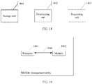
- FIG. 19 is a second schematic structural diagram of a mobility management entity according to an embodiment of the present invention.
- the mobility management entity may be the mobility management entity described above, and the mobility management entity includes a processor 1901 and a memory 1902.
- the memory 1902 is configured to store a correspondence between each GW-U identifier and a tracking area TA identifier list in advance.
- the processor 1901 is configured to: after a tracking area TA in which a user equipment UE is located changes, determine that an original TA in which the UE is located is corresponding to a first TA identifier, and determine that a new TA in which the UE is located is corresponding to a second TA identifier, where a first PDN connection is established between the UE and a first GW-U; and determine, according to the correspondence, that a TA list in which the first TA identifier is is corresponding to a first GW-U identifier, and determine that a TA list in which the second TA identifier is is corresponding to a second GW-U identifier; and configured to: when the first GW-U corresponding to the first GW-U identifier is different from a second GW-U corresponding to the second GW-U identifier, send, to the UE, a request message of re-establishing a PDN connection, where the request message is used to trigger the UE to
- the processor 1901 is further configured to send, to the UE, a request message of disconnecting the first PDN connection, where the request message carries a parameter that is used to indicate the UE to establish the second PDN connection.
- a bus architecture (represented by using a bus 1900) may include any quantity of interconnected buses and bridges, and the bus 1900 connects together a circuit of one or more processors represented by the processor 1901 and a circuit of a memory represented by the memory 1902.
- the bus 1900 may further connect, for example, a peripheral device or a voltage stabilizer to various other circuits such as a power management circuit.
- the processor 1901 is responsible for managing the bus 1900 and general processing.
- the memory 1902 may be configured to store data that is used when the processor 1901 performs an operation.
- FIG. 10 Various variation manners and specific examples in the foregoing user plane gateway updating method in the embodiments of FIG. 10 , FIG. 11A , and FIG. 11B are also applicable to the mobility management entity in this embodiment.
- the foregoing detailed description of the user plane gateway updating method a person skilled in the art can clearly know an implementation method of the mobility management entity in this embodiment. Therefore, for brevity of the specification, details are not described herein.
- the disclosed system, apparatus, and method may be implemented in other manners.
- the described apparatus embodiment is merely an example.
- the unit or the unit division is merely logical function division and may be other division in actual implementation.
- multiple units or components may be combined or integrated into another system, or some features may be ignored or not performed.
- the displayed or discussed mutual couplings or direct couplings or communication connections may be implemented by using some interfaces.
- the indirect couplings or communication connections between the apparatuses or units may be implemented in electronic, mechanical, or other forms.
- the units described as separate parts may or may not be physically separate, and parts displayed as units may or may not be physical units, may be located in one position, or may be distributed on multiple network units. Some or all of the units may be selected according to actual requirements to achieve the objectives of the solutions of the embodiments.
- functional units in the embodiments of this application may be integrated into one processing unit, or each of the units may exist alone physically, or two or more units are integrated into one unit.
- the integrated unit may be implemented in a form of hardware, or may be implemented in a form of a software functional unit.
- the integrated unit When the integrated unit is implemented in the form of a software functional unit and sold or used as an independent product, the integrated unit may be stored in a computer-readable storage medium. Based on such an understanding, the technical solutions of this application essentially, or the part contributing to the prior art, or all or a part of the technical solutions may be implemented in the form of a software product.
- the computer software product is stored in a storage medium and includes several indicateions for indicateing a computer device (which may be a personal computer, a server, a network device, or the like) or a processor (processor) to perform all or a part of the steps of the methods described in the embodiments of this application.
- the foregoing storage medium includes: any medium that can store program code, such as a USB flash drive, a portable hard disk, a ROM (Read-Only Memory, read-only memory), a RAM (Random Access Memory, random access memory), a magnetic disk, or an optical disc.
- program code such as a USB flash drive, a portable hard disk, a ROM (Read-Only Memory, read-only memory), a RAM (Random Access Memory, random access memory), a magnetic disk, or an optical disc.
- Embodiment 1 A user plane gateway updating method, comprising:
- Embodiment 2 The method according to embodiment 1, wherein the sending, by the GW-C to the MME, a request message of re-establishing a PDN connection comprises: sending, by the GW-C to the MME, the request message of re-establishing a PDN connection, wherein the request message is used to indicate the MME to delete the first PDN connection, and the request message carries a parameter that is used to indicate the UE to establish the second PDN connection.
- Embodiment 3 A user plane gateway updating method, comprising:
- Embodiment 4 The method according to embodiment 2, wherein the sending, by the GW-C to the MME, a request message of re-establishing a PDN connection comprises: sending, by the GW-C to the MME, the request message of re-establishing a PDN connection, wherein the request message is used to indicate the MME to delete the first PDN connection, and the request message carries a parameter that is used to indicate the UE to establish the second PDN connection.
- a user plane gateway updating method comprising:
- Embodiment 6 The method according to embodiment 5, wherein the sending, by the MME to the UE, a request message of re-establishing a PDN connection comprises: sending, by the MME, a request message of disconnecting the first PDN connection, wherein the request message carries a parameter that is used to indicate the UE to establish the second PDN connection.
- Embodiment 7 A user plane gateway updating method, comprising:
- Embodiment 8 The method according to embodiment 7, wherein the sending, by the MME to the UE, a request message of re-establishing a PDN connection comprises: sending, by the MME to the UE, a request message of disconnecting the first PDN connection, wherein the request message carries a parameter that is used to indicate the UE to establish the second PDN connection.
- a user plane gateway updating apparatus comprising:
- Embodiment 10 The apparatus according to embodiment 9, wherein the requesting unit is configured to: send, to the MME, the request message of re-establishing a PDN connection, wherein the request message is used to indicate the MME to delete the first PDN connection, and the request message carries a parameter that is used to indicate the UE to establish the second PDN connection.
- a user plane gateway updating apparatus comprising:
- Embodiment 12 The apparatus according to embodiment 11, wherein the requesting unit is configured to: send, to the MME, the request message of re-establishing a PDN connection, wherein the request message is used to indicate the MME to delete a default bearer of the first PDN connection, and the request message carries a parameter that is used to indicate the UE to establish the second PDN connection.
- a user plane gateway updating apparatus comprising:
- Embodiment 14 The apparatus according to embodiment 13, wherein the requesting unit is configured to: send a request message of disconnecting the first PDN connection, wherein the request message carries a parameter that is used to indicate the UE to establish the second PDN connection.
- a user plane gateway updating apparatus comprising:
- Embodiment 16 The apparatus according to embodiment 15, wherein the requesting unit is configured to: send, to the UE, a request message of disconnecting the first PDN connection, wherein the request message carries a parameter that is used to indicate the UE to establish the second PDN connection.
Abstract
Description
- The present invention relates to the field of communications technologies, and in particular, to a user plane gateway updating method and apparatus.
- System architecture evolution (System Architecture Evolution, SAE) is an upgrade plan of the 3GPP for a core network architecture of an LTE wireless communications standard. An SAE architecture is shown in
FIG. 1 . For the SAE architecture, if a UE moves across TAs, the UE triggers a tracking area update (Tracking Area Update, TAU). When neither an MME nor an S-GW changes, in a process of executing a TAU procedure, there is not any signaling interaction between the MME and the S-GW. A TA (Tracking Area) is a geographical area formed by continuously covered cells, and is used to manage a location of a UE that is in an idle state. - In the SAE architecture, a gateway still needs to keep a large quantity of external signaling interfaces. The large quantity of external signaling interfaces of the gateway bring a large amount of interface signaling. A gateway that uses a dedicated hardware platform does not have strong signaling processing performance, and therefore, easily becomes a bottleneck. Software-defined networking (Software Defined Network, SDN) provides an effective way to resolve the bottleneck problem of the gateway in signaling processing. An SDN-based SAE architecture is shown in
FIG. 2 . - With the rapid development of a mobile Internet and the popularity of intelligent terminals, mobile traffic presents a trend of an explosive growth. In order to avoid pressure that a growth in mobile traffic brings to a core network, a mobile gateway presents a trend of gradual downward deployment and distributed deployment. For the SDN-based SAE architecture shown in
FIG. 2 , GW-Us are further moved downwards and deployed in a distributed manner, implementing an architecture of distributed GW-U deployment shown inFIG. 3 . - However, in a distributed gateway architecture, in a process of executing a TAU procedure, it may be necessary to select a new GW-U and establish a new PDN (packet data network; English: Packet Data Network) connection for a UE. Because an MME cannot obtain information about GW-U deployment, GW-U updating cannot be implemented when neither the MME nor a GW-C changes.
- Embodiments of the present invention provide a user plane gateway updating method and apparatus, so as to resolve a prior-art technical problem that GW-U updating cannot be implemented when neither an MME nor a GW-C changes.
- A first aspect of the embodiments of the present invention provides a user plane gateway updating method, including:
- sending, by a control plane gateway GW-C to a mobility management entity MME, a first message that is used to indicate that a first packet data network PDN connection is established, where the first PDN connection is a PDN connection between a user equipment UE and a first user plane gateway GW-U, the first message carries a notification parameter, and the notification parameter is used to request the MME to notify the GW-C when a tracking area TA in which the UE is located changes;
- receiving, by the GW-C, a notification message sent by the MME, where the notification message is used to notify the GW-C that the tracking area TA in which the UE is located changes;
- determining, by the GW-C according to the notification message, that a new TA in which the UE is located is corresponding to a second GW-U, where the second GW-U is different from the first GW-U;
- sending, by the GW-C to the MME, a request message of re-establishing a PDN connection, where the request message is used to request the MME to trigger the UE to initiate a second PDN connection, and the second PDN connection is a PDN connection between the UE and the second GW-U; and
- establishing, by the GW-C, the second PDN connection by using the second GW-U.
- With reference to the first aspect, in a first possible implementation of the first aspect, the sending, by the GW-C to the MME, a request message of re-establishing a PDN connection includes:
sending, by the GW-C to the MME, the request message of re-establishing a PDN connection, where the request message is used to indicate the MME to delete the first PDN connection, and the request message carries a parameter that is used to indicate the UE to establish the second PDN connection. - A second aspect of the embodiments of the present invention provides a user plane gateway updating method, including:
- sending, by a control plane gateway GW-C to a mobility management entity MME, a first message that is used to indicate that a first packet data network PDN connection is established, where the first PDN connection is a PDN connection between a user equipment UE and a first user plane gateway GW-U, and the first message carries a TA identifier list corresponding to the first GW-U;
- receiving, by the GW-C, a notification message that the MME sends according to the first message, where the notification message is used to notify the GW-C that a TA identifier of a tracking area TA in which the UE is located is not in the TA identifier list;
- sending, by the GW-C to the MME, a request message of re-establishing a PDN connection, where the request message is used to request the MME to trigger the UE to initiate a second PDN connection, and the second PDN connection is a PDN connection between the UE and a second GW-U; and
- establishing, by the GW-C, the second PDN connection by using the second GW-U.
- With reference to the second aspect, in a first possible implementation of the second aspect, the sending, by the GW-C to the MME, a request message of re-establishing a PDN connection includes:
sending, by the GW-C to the MME, the request message of re-establishing a PDN connection, where the request message is used to indicate the MME to delete the first PDN connection, and the request message carries a parameter that is used to indicate the UE to establish the second PDN connection. - A third aspect of the embodiments of the present invention provides a user plane gateway updating method, including:
- receiving, by a mobility management entity MME, a first message that is used to indicate that a first packet data network PDN connection is established and that is sent by a control plane gateway GW-C, where the first PDN connection is a PDN connection between a user equipment UE and a first user plane gateway GW-U, and the first message carries a TA identifier list corresponding to the first GW-U;
- determining, by the MME, that a TA identifier of a tracking area TA in which the UE is located is not in the TA identifier list; and
- sending, by the MME to the UE, a request message of re-establishing a PDN connection, where the request message is used to trigger the UE to initiate a second PDN connection, and the second PDN connection is a PDN connection between the UE and a second GW-U.
- With reference to the third aspect, in a first possible implementation of the third aspect, the sending, by the MME to the UE, a request message of re-establishing a PDN connection includes:
sending, by the MME, a request message of disconnecting the first PDN connection, where the request message carries a parameter that is used to indicate the UE to establish the second PDN connection. - A fourth aspect of the embodiments of the present invention provides a user plane gateway updating method, including:
- after a tracking area TA in which a user equipment UE is located changes, determining, by a mobility management entity MME, that an original TA in which the UE is located is corresponding to a first TA identifier, and determining that a new TA in which the UE is located is corresponding to a second TA identifier, where a first PDN connection is established between the UE and a first GW-U;
- determining, by the MME according to a pre-stored correspondence between each GW-U identifier and a tracking area TA identifier list, that a TA list in which the first TA identifier is is corresponding to a first GW-U identifier, and determining that a TA list in which the second TA identifier is is corresponding to a second GW-U identifier; and
- when the first GW-U corresponding to the first GW-U identifier is different from a second GW-U corresponding to the second GW-U identifier, sending, by the MME to the UE, a request message of re-establishing a PDN connection, where the request message is used to trigger the UE to initiate a second PDN connection, and the second PDN connection is a PDN connection between the UE and the second GW-U.
- With reference to the fourth aspect, in a first possible implementation of the fourth aspect, the sending, by the MME to the UE, a request message of re-establishing a PDN connection includes:
sending, by the MME to the UE, a request message of disconnecting the first PDN connection, where the request message carries a parameter that is used to indicate the UE to establish the second PDN connection. - A fifth aspect of the embodiments of the present invention provides a user plane gateway updating apparatus, including:
- a sending unit, configured to send, to a mobility management entity MME, a first message that is used to indicate that a first packet data network PDN connection is established, where the first PDN connection is a PDN connection between a user equipment UE and a first user plane gateway GW-U, the first message carries a notification parameter, and the notification parameter is used to request the MME to notify the GW-C when a tracking area TA in which the UE is located changes;
- a receiving unit, configured to receive a notification message sent by the MME, where the notification message is used to notify the GW-C that the tracking area TA in which the UE is located changes;
- a determining unit, configured to determine, according to the notification message, that a new TA in which the UE is located is corresponding to a second GW-U, where the second GW-U is different from the first GW-U;
- a requesting unit, configured to send, to the MME, a request message of re-establishing a PDN connection, where the request message is used to request the MME to trigger the UE to initiate a second PDN connection, and the second PDN connection is a PDN connection between the UE and the second GW-U; and
- an establishment unit, configured to establish the second PDN connection by using the second GW-U. With reference to the fifth aspect, in a first possible implementation of the fifth aspect, the requesting unit is configured to:
send, to the MME, the request message of re-establishing a PDN connection, where the request message is used to indicate the MME to delete the first PDN connection, and the request message carries a parameter that is used to indicate the UE to establish the second PDN connection. - A sixth aspect of the embodiments of the present invention provides a user plane gateway updating apparatus, including:
- a sending unit, configured to send, to a mobility management entity MME, a first message that is used to indicate that a first packet data network PDN connection is established, where the first PDN connection is a PDN connection between a user equipment UE and a first user plane gateway GW-U, and the first message carries a TA identifier list corresponding to the first GW-U;
- a receiving unit, configured to receive a notification message that the MME sends according to the first message, where the notification message is used to notify the GW-C that a TA identifier of a tracking area TA in which the UE is located is not in the TA identifier list;
- a requesting unit, configured to send, to the MME, a request message of re-establishing a PDN connection, where the request message is used to request the MME to trigger the UE to initiate a second PDN connection, and the second PDN connection is a PDN connection between the UE and a second GW-U; and
- an establishment unit, configured to establish the second PDN connection by using the second GW-U.
- With reference to the sixth aspect, in a first possible implementation of the sixth aspect, the requesting unit is configured to:
send, to the MME, the request message of re-establishing a PDN connection, where the request message is used to indicate the MME to delete the first PDN connection, and the request message carries a parameter that is used to indicate the UE to establish the second PDN connection. - A seventh aspect of the embodiments of the present invention provides a user plane gateway updating apparatus, including:
- a receiving unit, configured to receive a first message that is used to indicate that a first packet data network PDN connection is established and that is sent by a control plane gateway GW-C, where the first PDN connection is a PDN connection between a user equipment UE and a first user plane gateway GW-U, and the first message carries a TA identifier list corresponding to the first GW-U;
- a determining unit, configured to determine that a TA identifier of a tracking area TA in which the UE is located is not in the TA identifier list; and
- a requesting unit, configured to send, to the UE, a request message of re-establishing a PDN connection, where the request message is used to trigger the UE to initiate a second PDN connection, and the second PDN connection is a PDN connection between the UE and a second GW-U.
- With reference to the seventh aspect, in a first possible implementation of the seventh aspect, the requesting unit is configured to:
send a request message of disconnecting the first PDN connection, where the request message carries a parameter that is used to indicate the UE to establish the second PDN connection. - An eighth aspect of the embodiments of the present invention provides a user plane gateway updating apparatus, including:
- a storage unit, configured to store a correspondence between each GW-U identifier and a tracking area TA identifier list in advance;
- a determining unit, configured to: after a tracking area TA in which a user equipment UE is located changes, determine that an original TA in which the UE is located is corresponding to a first TA identifier, and determine that a new TA in which the UE is located is corresponding to a second TA identifier, where a first PDN connection is established between the UE and a first GW-U; and determine, according to the correspondence, that a TA list in which the first TA identifier is is corresponding to a first GW-U identifier, and determine that a TA list in which the second TA identifier is is corresponding to a second GW-U identifier; and
- a requesting unit, configured to: when the first GW-U corresponding to the first GW-U identifier is different from a second GW-U corresponding to the second GW-U identifier, send, to the UE, a request message of re-establishing a PDN connection, where the request message is used to trigger the UE to initiate a second PDN connection, and the second PDN connection is a PDN connection between the UE and the second GW-U.
- With reference to the eighth aspect, in a first possible implementation of the eighth aspect, the requesting unit is configured to:
send, to the UE, a request message of disconnecting the first PDN connection, where the request message carries a parameter that is used to indicate the UE to establish the second PDN connection. - One or more technical solutions provided in the embodiments of the present invention have at least the following technical effects or advantages:
In the embodiments of the present invention, for a distributed gateway architecture, when the UE performs TAU, first, the GW-C or the MME determines that a GW-U corresponding to the new TA is different from a GW-U in an established PDN connection; then, the UE triggers PDN connection re-establishment; and the GW-C selects a new GW-U to complete the PDN connection re-establishment. This optimizes a data transmission path and ensures communication performance. - To describe the technical solutions in the embodiments of the present invention more clearly, the following briefly describes the accompanying drawings required for describing the embodiments. Apparently, the accompanying drawings in the following description show merely some embodiments of the present invention, and a person of ordinary skill in the art may still derive other drawings from these accompanying drawings without creative efforts.
-
FIG. 1 is a schematic diagram of an SAE architecture in the prior art; -
FIG. 2 is a schematic diagram of an SDN-based SAE architecture in the prior art; -
FIG. 3 is a schematic diagram of a distributed gateway architecture in the prior art; -
FIG. 4 is a flowchart of a first distributed gateway updating method according to an embodiment of the present invention; -
FIG. 5 is a schematic signaling interaction diagram of a first distributed gateway updating method according to an embodiment of the present invention; -
FIG. 6 is a flowchart of a second distributed gateway updating method according to an embodiment of the present invention; -
FIG. 7A andFIG. 7B are schematic signaling interaction diagrams of a second distributed gateway updating method according to an embodiment of the present invention; -
FIG. 8 is a flowchart of a third distributed gateway updating method according to an embodiment of the present invention; -
FIG. 9A andFIG. 9B are schematic signaling interaction diagrams of a third distributed gateway updating method according to an embodiment of the present invention; -
FIG. 10 is a flowchart of a fourth distributed gateway updating method according to an embodiment of the present invention; -
FIG. 11A andFIG. 11B are schematic signaling interaction diagrams of a fourth distributed gateway updating method according to an embodiment of the present invention; -
FIG. 12 is a first schematic module diagram of a user plane gateway updating apparatus according to an embodiment of the present invention; -
FIG. 13 is a first schematic structural diagram of a control plane gateway according to an embodiment of the present invention; -
FIG. 14 is a second schematic module diagram of a user plane gateway updating apparatus according to an embodiment of the present invention; -
FIG. 15 is a second schematic structural diagram of a control plane gateway according to an embodiment of the present invention; -
FIG. 16 is a third schematic module diagram of a user plane gateway updating apparatus according to an embodiment of the present invention; -
FIG. 17 is a first schematic structural diagram of a mobility management entity according to an embodiment of the present invention; -
FIG. 18 is a fourth schematic module diagram of a user plane gateway updating apparatus according to an embodiment of the present invention; and -
FIG. 19 is a second schematic structural diagram of a mobility management entity according to an embodiment of the present invention. - To make the objectives, technical solutions, and advantages of the embodiments of the present invention clearer, the following clearly and completely describes the technical solutions in the embodiments of the present invention with reference to the accompanying drawings in the embodiments of the present invention. Apparently, the described embodiments are some but not all of the embodiments of the present invention. All other embodiments obtained by a person of ordinary skill in the art based on the embodiments of the present invention without creative efforts shall fall within the protection scope of the present invention.
- The term "and/or" in this specification describes only an association relationship for describing associated objects and represents that three relationships may exist. For example, A and/or B may represent the following three cases: Only A exists, both A and B exist, and only B exists. In addition, the character "/" in this specification generally indicates an "or" relationship between the associated objects.
- Referring to
FIG. 3 , a distributed gateway architecture shown inFIG. 3 is applicable to a user plane gateway updating method according to an embodiment of the present invention. The following briefly describes main network elements inFIG 3 . - A UE (user equipment; English: User Equipment), also referred to as a mobile terminal (Mobile Terminal), mobile user equipment, or the like, may communicate with one or more core networks (CN, Core Network) by using a radio access network (RAN, Radio Access Network). The user equipment may be, for example, a mobile phone or a computer with a mobile terminal, such as a portable, pocket-sized, handheld, computer built-in, or in-vehicle mobile apparatus. For example, the user equipment may be a mobile phone, an intelligent terminal, a multimedia device, or a streaming media device.
- An eNodeB (evolved Node B; English: Evolved Node B) is a wireless base station in an LTE network. The eNodeB is an only network element in an LTE radio access network and is responsible for all functions related to an air interface. The eNodeB may alternatively be a base station (BTS, Base Transceiver Station) in GSM or CDMA, or may be a base station (NodeB) in WCDMA, or a network device that implements a similar function in a subsequent evolved system, which is not limited in the present invention. It should be noted that a corresponding change made for a form of a network device according to an actual network deployment requirement, for example, using a distributed base station, is also within the protection scope of the present invention.
- An MME (mobility management entity; English: Mobility Management Entity) is a network element, in an LTE core network, that is responsible for processing signaling. The MME is responsible for mobility management in a control plane, including user context and mobile status management.
- GW-Cs (control plane gateway; English: Gateway Control-plane) are deployed together. The GW-C is responsible for processing an external signaling interaction, including GTP-C signaling between the GW-C and an MME and signaling between the GW-C and another network element.
- GW-Us (user plane gateway; English: Gateway User-plane) are deployed in a distributed manner. The GW-U is configured to forward a user data packet according to context information indicated by the GW-C.
- The embodiments of the present invention mainly propose two mechanisms for implementing GW-U updating. The two mechanisms are separately described as follows:
- In a first mechanism, in a process of executing a TAU procedure, the MME notifies the GW-C by using a predetermined mechanism, and the GW-C initiates a PDN release and re-establishment procedure to complete GW-U updating.
- In a second mechanism, the MME obtains a mapping relationship between a GW-U and a TA in advance, and in a process of executing a TAU procedure, the MME proactively initiates a PDN release and re-establishment procedure to complete GW-U updating.
-
Embodiment 1 details how GW-U updating is implemented in a first mechanism. As shown inFIG. 4 , in the first mechanism, a first method for implementing GW-U updating includes the following steps. - Step 401: A control plane gateway GW-C sends, to a mobility management entity MME, a first message that is used to indicate that a first PDN connection is established, where the first packet data network PDN connection is a PDN connection between a user equipment UE and a first user plane gateway GW-U, the first message carries a notification parameter, and the notification parameter is used to request the MME to notify the GW-C when a tracking area TA in which the UE is located changes.
- Step 402: The GW-C receives a notification message sent by the MME, where the notification message is used to notify the GW-C that the tracking area TA in which the UE is located changes.
- Step 403: The GW-C determines, according to the notification message, that a new TA in which the UE is located is corresponding to a second GW-U, where the second GW-U is different from the first GW-U.
- Step 404: The GW-C sends, to the MME, a request message of re-establishing a PDN connection, where the request message is used to request the MME to trigger the UE to initiate a second PDN connection, and the second PDN connection is a PDN connection between the UE and the second GW-U.
- Step 405: The GW-C establishes the second PDN connection by using the second GW-U.
- That the GW-C sends, to the MME, a request message of re-establishing a PDN connection includes:
the GW-C sends, to the MME, the request message of re-establishing a PDN connection, where the request message is used to indicate the MME to delete the first PDN connection, and the request message carries a parameter that is used to indicate the UE to establish the second PDN connection. - Specifically, in a process in which the UE attaches to a network or in a process in which the first PDN connection between the UE and the first GW-U is being established, the GW-C sends a change reporting action (English: Change Reporting Action) parameter to the MME, to request the MME to notify the GW-C when the TA in which the UE is located changes. If the UE triggers execution of a TAU procedure, the MME sends a change notification (English: Change Notification) message to the GW-C, to notify the GW-C that the TA in which the UE is located changes. The GW-C determines, according to a new TA in which the UE is located, whether GW-U updating is required, and triggers and completes, if GW-U updating is required, GW-U updating and establishment of a new PDN connection.
- In order to establish the PDN connection between the UE and the first GW-U, signaling interactions shown in A1 to A4 in
FIG. 5 need to be performed between network elements. - A1) The UE sends a PDN connection establishment request (English: PDN Connectivity Request) message to the MME, to request to establish the first PDN connection.
- A2) The MME sends a create session request (English: Create Session Request) message to the GW-C, to request to create a session.
- A3) The GW-C selects the first GW-U, and sets a change reporting action parameter in a create session response (English: Create Session Response) message to be returned to the MME, to request the MME to notify the GW-C when the TA in which the UE is located changes.
- A4) The network elements complete other steps of establishing the first PDN connection.
- If the UE triggers the execution of the TAU procedure, that is, the TA in which the UE is located changes, in a process of executing the TAU procedure, signaling interactions shown in 1 to 10 in
FIG. 5 need to be performed between the network elements. - 1) The UE triggers TAU.
- 2) The UE sends a TAU request message to an eNodeB to initiate TAU.
- 3) The eNodeB forwards the TAU request message to the MME
- 4) The MME sends a change notification message to the GW-C, to notify the GW-C of information that the TA in which the UE is located changes.
- 5) After receiving the change notification message, the GW-C returns a change notification acknowledgement (English: Change Notification Ack) message to the MME
- 6) The MME sends a TAU accept message to the UE.
- 7) The UE sends a TAU complete message to the MME
- 8) The GW-C determines, according to a correspondence between the new TA in which the UE is located and GW-Us that are deployed in a distributed manner, whether GW-U updating is required; and if GW-U updating is required, the GW-C sends a delete bearer request (English: Delete Bearer Request) message to the MME, to indicate the MME to delete a default bearer of the first PDN connection, and sets a cause in the message to "Reactivation Requested".
- 9) The network elements complete a procedure of deactivating the default bearer of the first PDN connection.
- 10) According to an indication of the "Reactivation Requested" parameter, the UE initiates a new PDN connection request. The GW-C selects the second GW-U, and completes a process of establishing the PDN connection between the UE and the second GW-U.
- In the foregoing process, if a GW-U updating procedure does not need to be executed, steps 8) to 10) are not performed.
- In
Embodiment 1, the Change Reporting Action is set, so that when the UE performs TAU, the MME proactively notifies the GW-C, and the GW-C determines, according to the new TA in which the UE is located, whether GW-U updating is required, and triggers and completes, if GW-U updating is required, GW-U updating and PDN connection re-establishment. - On the one hand,
Embodiment 1 resolves a problem that an existing TAU procedure cannot implement GW-U updating, and the GW-C can select, according to a current location of the UE, a best GW-U and establish a PDN connection, thereby optimizing a data transmission path and ensuring communication performance. On the other hand, inEmbodiment 1, an existing Location Change Reporting procedure is used to implement a function of notifying the GW-C by the MME, without changing the MME, so that implementation costs are reduced. -
Embodiment 2 details how GW-U updating is implemented in a first mechanism. As shown inFIG. 6 , in the first mechanism, a second method for implementing GW-U updating includes the following steps. - Step 601: A control plane gateway GW-C sends, to a mobility management entity MME, a first message that is used to indicate that a first packet data network PDN connection is established, where the first PDN connection is a PDN connection between a user equipment UE and a first user plane gateway GW-U, and the first message carries a TA identifier list corresponding to the first GW-U.
- Step 602: The GW-C receives a notification message that the MME sends according to the first message, where the notification message is used to notify the GW-C that a TA identifier of a tracking area TA in which the UE is located is not in the TA identifier list.
- Step 603: The GW-C sends, to the MME, a request message of re-establishing a PDN connection, where the request message is used to request the MME to trigger the UE to initiate a second PDN connection, and the second PDN connection is a PDN connection between the UE and a second GW-U.
- Step 604: The GW-C establishes the second PDN connection by using the second GW-U.
- That the GW-C sends, to the MME, a request message of re-establishing a PDN connection includes:
the GW-C sends, to the MME, the request message of re-establishing a PDN connection, where the request message is used to indicate the MME to delete the first PDN connection, and the request message carries a parameter that is used to indicate the UE to establish the second PDN connection. - Specifically, in a process in which the UE attaches to a network or in a process in which the first PDN connection between the UE and the first GW-U is being established, the GW-C sends, to the MME, the TA list corresponding to the first GW-U. If the UE triggers execution of a TAU procedure, the MME determines whether a new TA in which the UE is located is in the TA list corresponding to the first GW-U. If the new TA in which the UE is located is not in the TA list corresponding to the first GW-U, the MME sends a change notification message to the GW-C, and the GW-C triggers a completion of GW-U updating and establishment of a new PDN connection.
- Compared with
Embodiment 1, inEmbodiment 2, it is considered that not every TAU causes GW-U updating, because there may be a case in which both a TA before TAU and a TA after the TAU are corresponding to the first GW-U. Therefore, different from a case, inEmbodiment 1, in which the MME sends a change notification message to the GW-C each time when the UE triggers the execution of the TAU procedure, inEmbodiment 2, the MME notifies the GW-C only after the UE leaves the TA list corresponding to the first GW-U (that is, only when TAU triggered by the UE causes GW-U updating). Therefore, compared withEmbodiment 1, inEmbodiment 2, a signaling load is reduced to some extent. - In order to establish the PDN connection between the UE and the first GW-U, signaling interactions shown in A1 to A4 in
FIG. 7A need to be performed between network elements. - A1) The UE sends a PDN connection establishment request message to the MME, to request to establish the first PDN connection.
- A2) The MME sends a create session request message to the GW-C, to request to create a session.
- A3) The GW-C selects the first GW-U, and sets, in a create session response message to be returned to the MME, the TA list corresponding to the first GW-U, and the MME stores the TA list for each UE.
- A4) The network elements complete other steps of establishing the first PDN connection.
- If the UE triggers the execution of the TAU procedure, that is, the TA in which the UE is located changes, in a process of executing the TAU procedure, signaling interactions shown in 1 to 10 in
FIG. 7A andFIG. 7B need to be performed between the network elements. - 1) The UE triggers TAU.
- 2) The UE sends a TAU request message to an eNodeB to initiate TAU.
- 3) The eNodeB forwards the TAU request message to the MME.
- 4) The MME determines whether the new TA in which the UE is located is in the TA list corresponding to the first GW-U. If the new TA in which the UE is located is not in the TA list corresponding to the first GW-U, the MME sends a change notification message to the GW-C.
- 5) After receiving the change notification message, the GW-C returns a change notification ack message to the MME
- 6) The MME sends a TAU accept message to the UE.
- 7) The UE sends a TAU complete message to the MME
- 8) After receiving the change notification message, the GW-C sends a delete bearer request message to the MME, to indicate the MME to delete a default bearer of the first PDN connection, and sets a cause in the message to "Reactivation Requested".
- 9) The network elements complete a procedure of deactivating the default bearer of the first PDN connection.
- 10) According to an indication of the "Reactivation Requested" parameter, the UE initiates a new PDN connection request. The GW-C selects the second GW-U, and completes a process of establishing the PDN connection between the UE and the second GW-U.
- In the foregoing process, if a GW-U updating procedure does not need to be executed, steps 4), 5), and 8) to 10) are not performed.
- In
Embodiment 2, the TA list corresponding to the first GW-U is set, so that when the UE performs TAU, the MME notifies the GW-C only after the UE leaves the TA list corresponding to the first GW-U, and the GW-C triggers and completes GW-U updating and PDN connection re-establishment. - On the one hand, compared with
Embodiment 1, inEmbodiment 2, a quantity of unnecessary change notification messages is reduced, and the signaling load is reduced. On the other hand, inEmbodiment 2, an existing Presence Reporting Area procedure is used to implement a function of notifying, by the MME, the GW-C when the UE leaves a specific TA list, without changing the MME, so that implementation costs are reduced. -
Embodiment 3 details how GW-U updating is implemented in a second mechanism. As shown inFIG. 8 , in the second mechanism, a first method for implementing GW-U updating includes the following steps. - Step 801: A mobility management entity MME receives a first message that is used to indicate that a first packet data network PDN connection is established and that is sent by a control plane gateway GW-C, where the first PDN connection is a PDN connection between a user equipment UE and a first user plane gateway GW-U, and the first message carries a TA identifier list corresponding to the first GW-U.
- Step 802: The MME determines that a TA identifier of a tracking area TA in which the UE is located is not in the TA identifier list.
- Step 803: The MME sends, to the UE, a request message of re-establishing a PDN connection, where the request message is used to trigger the UE to initiate a second PDN connection, and the second PDN connection is a PDN connection between the UE and a second GW-U.
- That the MME sends, to the UE, a request message of re-establishing a PDN connection includes:
the MME sends a request message of disconnecting the first PDN connection, where the request message carries a parameter that is used to indicate the UE to establish the second PDN connection. - Specifically, in a process in which the UE attaches to a network or in a process in which the first PDN connection between the UE and the first GW-U is being established, the GW-C sends, to the MME, the TA list corresponding to the first GW-U. If the UE triggers execution of a TAU procedure, the MME determines whether a new TA in which the UE is located is in the TA list corresponding to the first GW-U. If the new TA in which the UE is located is not in the TA list corresponding to the first GW-U, the MME triggers and completes GW-U updating and establishment of a new PDN connection.
- Compared with
Embodiment 2, inEmbodiment 3, when the UE leaves the TA list corresponding to the first GW-U (that is, when TAU triggered by the UE causes GW-U updating), the MME no long notifies the GW-C as it does inEmbodiment 2. Instead, the MME proactively initiates and completes GW-U updating and PDN connection re-establishment. - In order to establish the PDN connection between the UE and the first GW-U, signaling interactions shown in A1 to A4 in
FIG. 9A need to be performed between network elements. - A1) The UE sends a PDN connection establishment request message to the MME, to request to establish the first PDN connection.
- A2) The MME sends a create session request message to the GW-C, to request to create a session.
- A3) The GW-C selects the first GW-U, and sets, in a create session response message to be returned to the MME, the TA list corresponding to the first GW-U, and the MME stores the TA list for each UE.
- A4) The network elements complete other steps of establishing the first PDN connection.
- If the UE triggers the execution of the TAU procedure, that is, the TA in which the UE is located changes, in a process of executing the TAU procedure, signaling interactions shown in 1 to 7 in
FIG. 9A andFIG. 9B need to be performed between the network elements. - 1) The UE triggers TAU.
- 2) The UE sends a TAU request message to an eNodeB to initiate TAU.
- 3) The eNodeB forwards the TAU request message to the MME.
- 4) The MME sends a TAU accept message to the UE.
- 5) The UE sends a TAU complete message to the MME.
- 6) The MME determines whether the new TA in which the UE is located is in the TA list corresponding to the first GW-U. If the new TA in which the UE is located is not in the TA list corresponding to the first GW-U, the MME initiates a PDN disconnection procedure, and sets a cause in a message to "Reactivation Requested".
- 7) According to an indication of the "Reactivation Requested" parameter, the UE initiates a new PDN connection request. The GW-C selects the second GW-U, and completes a process of establishing the PDN connection between the UE and the second GW-U.
- In the foregoing process, if a GW-U updating procedure does not need to be executed, steps 6) and 7) are not performed.
- In
Embodiment 3, the TA list corresponding to the first GW-U is set, so that when the UE performs TAU, the MME proactively initiates and completes GW-U updating and PDN connection re-establishment only after the UE leaves the TA list corresponding to the first GW-U. - In
Embodiment 3, a function expansion needs to be performed on the MME, so that the MME can determine whether TAU causes GW-U updating, and initiate and complete GW-U updating and PDN connection re-establishment. Compared withEmbodiment 2, inEmbodiment 3, a quantity of signaling interactions between the MME and a GW-U (change notification and change notification ack messages in Embodiment 2) is reduced, and a signaling load is further reduced. -
Embodiment 4 details how GW-U updating is implemented in a second mechanism. As shown inFIG. 10 , in the second mechanism, a second method for implementing GW-U updating includes the following steps. - Step 101: After a tracking area TA in which a user equipment UE is located changes, a mobility management entity MME determines that an original TA in which the UE is located is corresponding to a first TA identifier, and determines that a new TA in which the UE is located is corresponding to a second TA identifier, where a first PDN connection is established between the UE and a first GW-U.
- Step 102: The MME determines, according to a pre-stored correspondence between each GW-U identifier and a tracking area TA identifier list, that a TA list in which the first TA identifier is is corresponding to a first GW-U identifier, and determines that a TA list in which the second TA identifier is is corresponding to a second GW-U identifier.
- Step 103: When the first GW-U corresponding to the first GW-U identifier is different from a second GW-U corresponding to the second GW-U identifier, the MME sends, to the UE, a request message of re-establishing a PDN connection, where the request message is used to trigger the UE to initiate a second PDN connection, and the second PDN connection is a PDN connection between the UE and the second GW-U.
- That the MME sends, to the UE, a request message of re-establishing a PDN connection includes:
the MME sends, to the UE, a request message of disconnecting the first PDN connection, where the request message carries a parameter that is used to indicate the UE to establish the second PDN connection. Specifically, a TA list corresponding to each GW-U is sent to the MME by using device-level signaling. If the UE triggers execution of a TAU procedure, the MME determines whether a GW-U corresponding to the new TA in which the UE is located is the same as a GW-U corresponding to the original TA in which the UE is located. If the GW-U corresponding to the new TA in which the UE is located is different from the GW-U corresponding to the original TA in which the UE is located, the MME triggers and completes GW-U updating and establishment of a new PDN connection. - If the UE triggers the execution of the TAU procedure, that is, the TA in which the UE is located changes, in a process of executing the TAU procedure, signaling interactions shown in 0 to 7 in
FIG. 11A andFIG. 11B need to be performed between network elements. - 0) The GW-C sends a mapping table between a GW-U and a TA, {[GW-U ID, TA list], ...}, to the MME, or configures in advance, in the MME, the mapping table between a GW-U and a TA, {[GW-U ID, TA list], ...}. Later, during UE attach or establishment of the first PDN connection, the MME may obtain, according to the TA in which the UE is located and by means of calculation, that a corresponding GW-U ID is the first GW-U.
- 1) The UE triggers TAU.
- 2) The UE sends a TAU request message to an eNodeB to initiate TAU.
- 3) The eNodeB forwards the TAU request message to the MME.
- 4) The MME sends a TAU accept message to the UE.
- 5) The UE sends a TAU complete message to the MME
- 6) The MME searches the mapping table between a GW-U and a TA, determines that the new TA in which the UE is located is corresponding to the second GW-U, and determines whether the second GW-U is the same as the first GW-U. If the second GW-U is different from the first GW-U, the MME initiates a PDN disconnection (English: PDN disconnection) procedure, and sets a cause in a message to "Reactivation Requested".
- 7) According to an indication of the "Reactivation Requested" parameter, the UE initiates a new PDN connection request. The GW-C selects a new GW-U, and completes a process of establishing a PDN connection between the UE and the newly selected GW-U.
- In the foregoing process, if a GW-U updating procedure does not need to be executed, steps 6) and 7) are not performed.
- In
Embodiment 4, because a GW-U status may change (addition, deletion, a location change, a change of a corresponding TA list, and the like), after step 0) is performed, signaling interactions shown in 8) and 9) inFIG. 11B need to be performed between the network elements. - 8) When a GW-U status changes (addition, deletion, a location change, a change of a corresponding TA list, and the like), a GW-U whose status changes notifies the GW-C.
- 9) The GW-C sends, according to GW-U status change information, the updated mapping table between a GW-U and a TA to the MME
- In the foregoing process, step 8) is performed only when the GW-U status changes, and step 9) is performed only when a mapping relationship between a GW-U and a TA list changes.
- In
Embodiment 4, the GW-C transfers the mapping table between a GW-U and a TA to the MME by using the device-level signaling, so that when the UE performs TAU, the MME can search the mapping table, to determine whether GW-U updating is required, and when determining that GW-U updating is required, the MME proactively initiates and completes GW-U updating and PDN connection re-establishment. In addition, when the GW-U status changes, the GW-C updates the mapping table between a GW-U and a TA by using a device-level message. - In
embodiment 4, a function expansion needs to be performed on the MME, so that the MME can receive and process the mapping table between a GW-U and a TA, determine whether TAU causes GW-U updating, and initiate and complete GW-U updating and PDN connection re-establishment. Compared withEmbodiment 1 toEmbodiment 3, inEmbodiment 4, on the one hand, the device-level signaling is used to transfer the mapping table between a GW-U and a TA, and a signaling load of a system is further reduced; on the other hand, when the GW-U status changes, a new mapping relationship can be sent to the MME in a timely manner, thereby ensuring that the MME can correctly determine whether GW-U updating is required. - Compared with
Embodiment 1 andEmbodiment 2, inEmbodiment 3 andEmbodiment 4, proactively initiating, by the MME, a PDN re-establishment procedure is actually using the PDN disconnection procedure to trigger the UE to initiate PDN connection re-establishment, whereas inEmbodiment 1 andEmbodiment 2, initiating, by the GW-C, the PDN re-establishment procedure is actually using the procedure of deactivating the default bearer of the first PDN connection to trigger the UE to initiate PDN connection re-establishment. - Compared with
Embodiment 2 andEmbodiment 3, inEmbodiment 4, the GW-C sends the mapping table between a GW-U and a TA to the MME, or configures in advance, in the MME, the mapping table between a GW-U and a TA. Therefore, in a process in which the UE establishes the PDN connection with the first GW-U, the TA list corresponding to the first GW-U is not transferred again. - In conclusion, to resolve a prior-art technical problem that GW-U updating is not supported in the process of executing the TAU procedure, the embodiments of the present invention provide four different solutions. For purposes of being compatible with an existing implementation mechanism and improving system efficiency, when the UE performs TAU, an EPS system of a distributed gateway can select, according to a current location of the UE, a best GW-U and re-establish a PDN connection, thereby optimizing a data transmission path and ensuring communication performance.
- Based on a same inventive concept, an embodiment of the present invention further provides a user plane gateway updating apparatus.
- Referring to
FIG. 12, FIG. 12 is a first schematic module diagram of a user plane gateway updating apparatus according to an embodiment of the present invention. For a meaning of a term used in and specific implementation of the user plane gateway updating apparatus shown inFIG. 12 , reference may be made to a related description ofFIG. 1 to FIG. 11B and the foregoing embodiments. The apparatus may be the control plane gateway described above, and the apparatus includes a sendingunit 1201, areceiving unit 1202, a determiningunit 1203, a requestingunit 1204, and anestablishment unit 1205. - The sending
unit 1201 is configured to send, to a mobility management entity MME, a first message that is used to indicate that a first packet data network PDN connection is established, where the first PDN connection is a PDN connection between a user equipment UE and a first user plane gateway GW-U, the first message carries a notification parameter, and the notification parameter is used to request the MME to notify a GW-C when a tracking area TA in which the UE is located changes. - The receiving
unit 1202 is configured to receive a notification message sent by the MME, where the notification message is used to notify the GW-C that the tracking area TA in which the UE is located changes. - The determining
unit 1203 is configured to determine, according to the notification message, that a new TA in which the UE is located is corresponding to a second GW-U, where the second GW-U is different from the first GW-U. - The requesting
unit 1204 is configured to send, to the MME, a request message of re-establishing a PDN connection, where the request message is used to request the MME to trigger the UE to initiate a second PDN connection, and the second PDN connection is a PDN connection between the UE and the second GW-U. - The
establishment unit 1205 is configured to establish the second PDN connection by using the second GW-U. Optionally, the requestingunit 1204 is configured to:
send, to the MME, the request message of re-establishing a PDN connection, where the request message is used to indicate the MME to delete the first PDN connection, and the request message carries a parameter that is used to indicate the UE to establish the second PDN connection. - Various variation manners and specific examples in the foregoing user plane gateway updating method in the embodiments of
FIG. 4 andFIG. 5 are also applicable to the user plane gateway updating apparatus in this embodiment. According to the foregoing detailed description of the user plane gateway updating method, a person skilled in the art can clearly know an implementation method of the user plane gateway updating apparatus in this embodiment. Therefore, for brevity of the specification, details are not described herein. - Referring to
FIG. 13, FIG. 13 is a first schematic structural diagram of a control plane gateway according to an embodiment of the present invention. For a meaning of a term used in and specific implementation of the user plane gateway shown inFIG. 13 , reference may be made to a related description ofFIG. 1 to FIG. 11B and the foregoing embodiments. The control plane gateway may be the control plane gateway described above, and the control plane gateway includes asender 1301, areceiver 1302, aprocessor 1303, and amemory 1304. - The
sender 1301 is configured to send, to a mobility management entity MME, a first message that is used to indicate that a first packet data network PDN connection is established, where the first PDN connection is a PDN connection between a user equipment UE and a first user plane gateway GW-U, the first message carries a notification parameter, and the notification parameter is used to request the MME to notify a GW-C when a tracking area TA in which the UE is located changes. - The
receiver 1302 is configured to receive a notification message sent by the MME, where the notification message is used to notify the GW-C that the tracking area TA in which the UE is located changes. - The
processor 1303 is configured to determine, according to the notification message, that a new TA in which the UE is located is corresponding to a second GW-U, where the second GW-U is different from the first GW-U; configured to send, to the MME, a request message of re-establishing a PDN connection, where the request message is used to request the MME to trigger the UE to initiate a second PDN connection, and the second PDN connection is a PDN connection between the UE and the second GW-U; and configured to establish the second PDN connection by using the second GW-U. - Optionally, the
processor 1303 is further configured to send, to the MME, the request message of re-establishing a PDN connection, where the request message is used to indicate the MME to delete the first PDN connection, and the request message carries a parameter that is used to indicate the UE to establish the second PDN connection. - In
FIG. 13 , a bus architecture (represented by using a bus 1300) may include any quantity of interconnected buses and bridges, and thebus 1300 connects together a circuit of one or more processors represented by theprocessor 1303 and a circuit of a memory represented by thememory 1304. Thebus 1300 may further connect, for example, a peripheral device or a voltage stabilizer to various other circuits such as a power management circuit. These are well known in the art, and therefore are not further described in this specification any more. Abus interface 1305 provides an interface between thebus 1300 and thereceiver 1302 and an interface between thebus 1300 and thesender 1301. Thereceiver 1302 and thesender 1301 may be one component, that is, a transceiver that provides a unit configured to communicate with various other apparatuses on a transmission medium. - The
processor 1303 is responsible for managing thebus 1300 and general processing. Thememory 1304 may be configured to store data that is used when theprocessor 1303 performs an operation. - Various variation manners and specific examples in the foregoing user plane gateway updating method in the embodiments of
FIG. 4 andFIG. 5 are also applicable to the control plane gateway in this embodiment. According to the foregoing detailed description of the user plane gateway updating method, a person skilled in the art can clearly know an implementation method of the control plane gateway in this embodiment. Therefore, for brevity of the specification, details are not described herein. - Referring to
FIG. 14, FIG. 14 is a second schematic module diagram of a user plane gateway updating apparatus according to an embodiment of the present invention. For a meaning of a term used in and specific implementation of the user plane gateway updating apparatus shown inFIG. 14 , reference may be made to a related description ofFIG. 1 to FIG. 11B and the foregoing embodiments. The apparatus may be the control plane gateway described above, and the apparatus includes a sendingunit 1401, areceiving unit 1402, a requestingunit 1403, and anestablishment unit 1404. - The sending
unit 1401 is configured to send, to a mobility management entity MME, a first message that is used to indicate that a first packet data network PDN connection is established, where the first PDN connection is a PDN connection between a user equipment UE and a first user plane gateway GW-U, and the first message carries a TA identifier list corresponding to the first GW-U. - The receiving
unit 1402 is configured to receive a notification message that the MME sends according to the first message, where the notification message is used to notify a GW-C that a TA identifier of a tracking area TA in which the UE is located is not in the TA identifier list. - The requesting
unit 1403 is configured to send, to the MME, a request message of re-establishing a PDN connection, where the request message is used to request the MME to trigger the UE to initiate a second PDN connection, and the second PDN connection is a PDN connection between the UE and a second GW-U. - The
establishment unit 1404 is configured to establish the second PDN connection by using the second GW-U. Optionally, the requestingunit 1403 is configured to:
send, to the MME, the request message of re-establishing a PDN connection, where the request message is used to indicate the MME to delete the first PDN connection, and the request message carries a parameter that is used to indicate the UE to establish the second PDN connection. - Various variation manners and specific examples in the foregoing user plane gateway updating method in the embodiments of
FIG. 6 ,FIG. 7A , andFIG. 7B are also applicable to the user plane gateway updating apparatus in this embodiment. According to the foregoing detailed description of the user plane gateway updating method, a person skilled in the art can clearly know an implementation method of the user plane gateway updating apparatus in this embodiment. Therefore, for brevity of the specification, details are not described herein. - Referring to
FIG. 15, FIG. 15 is a second schematic structural diagram of a control plane gateway according to an embodiment of the present invention. For a meaning of a term used in and specific implementation of the user plane gateway shown inFIG. 15 , reference may be made to a related description of the foregoingFIG. 1 to FIG. 11B and the embodiments. The control plane gateway may be the control plane gateway described above, and the control plane gateway includes asender 1501, areceiver 1502, aprocessor 1503, and amemory 1504. - The
sender 1501 is configured to send, to a mobility management entity MME, a first message that is used to indicate that a first packet data network PDN connection is established, where the first PDN connection is a PDN connection between a user equipment UE and a first user plane gateway GW-U, and the first message carries a TA identifier list corresponding to the first GW-U. - The
receiver 1502 is configured to receive a notification message that the MME sends according to the first message, where the notification message is used to notify a GW-C that a TA identifier of a tracking area TA in which the UE is located is not in the TA identifier list. - The
processor 1503 is configured to send, to the MME, a request message of re-establishing a PDN connection, where the request message is used to request the MME to trigger the UE to initiate a second PDN connection, and the second PDN connection is a PDN connection between the UE and a second GW-U; and configured to establish the second PDN connection by using the second GW-U. - Optionally, the
processor 1503 is further configured to send, to the MME, the request message of re-establishing a PDN connection, where the request message is used to indicate the MME to delete the first PDN connection, and the request message carries a parameter that is used to indicate the UE to establish the second PDN connection. - In
FIG. 15 , a bus architecture (represented by using a bus 1500) may include any quantity of interconnected buses and bridges, and thebus 1500 connects together a circuit of one or more processors represented by theprocessor 1503 and a circuit of a memory represented by thememory 1504. Thebus 1500 may further connect, for example, a peripheral device or a voltage stabilizer to various other circuits such as a power management circuit. These are well known in the art, and therefore are not further described in this specification any more. Abus interface 1505 provides an interface between thebus 1500 and thereceiver 1502 and an interface between thebus 1500 and thesender 1501. Thereceiver 1502 and thesender 1501 may be one component, that is, a transceiver that provides a unit configured to communicate with various other apparatuses on a transmission medium. - The
processor 1503 is responsible for managing thebus 1500 and general processing. Thememory 1504 may be configured to store data that is used when theprocessor 1503 performs an operation. - Various variation manners and specific examples in the foregoing user plane gateway updating method in the embodiments of
FIG. 6 ,FIG. 7A , andFIG. 7B are also applicable to the control plane gateway in this embodiment. According to the foregoing detailed description of the user plane gateway updating method, a person skilled in the art can clearly know an implementation method of the control plane gateway in this embodiment. Therefore, for brevity of the specification, details are not described herein. - Referring to
FIG. 16, FIG. 16 is a third schematic module diagram of a user plane gateway updating apparatus according to an embodiment of the present invention. For a meaning of a term used in and specific implementation of the user plane gateway updating apparatus shown inFIG. 16 , reference may be made to a related description ofFIG. 1 to FIG. 11B and the foregoing embodiments. The apparatus may be the mobility management entity described above, and the apparatus includes areceiving unit 1601, a determiningunit 1602, and a requestingunit 1603. - The receiving
unit 1601 is configured to receive a first message that is used to indicate that a first packet data network PDN connection is established and that is sent by a control plane gateway GW-C, where the first PDN connection is a PDN connection between a user equipment UE and a first user plane gateway GW-U, and the first message carries a TA identifier list corresponding to the first GW-U. - The determining
unit 1602 is configured to determine that a TA identifier of a tracking area TA in which the UE is located is not in the TA identifier list. - The requesting
unit 1603 is configured to send, to the UE, a request message of re-establishing a PDN connection, where the request message is used to trigger the UE to initiate a second PDN connection, and the second PDN connection is a PDN connection between the UE and a second GW-U. - Optionally, the requesting
unit 1603 is configured to:
send a request message of disconnecting the first PDN connection, where the request message carries a parameter that is used to indicate the UE to establish the second PDN connection. - Various variation manners and specific examples in the foregoing user plane gateway updating method in the embodiments of
FIG. 8 ,FIG. 9A , andFIG. 9B are also applicable to the user plane gateway updating apparatus in this embodiment. According to the foregoing detailed description of the user plane gateway updating method, a person skilled in the art can clearly know an implementation method of the user plane gateway updating apparatus in this embodiment. Therefore, for brevity of the specification, details are not described herein. - Referring to
FIG. 17, FIG. 17 is a first schematic structural diagram of a mobility management entity according to an embodiment of the present invention. For a meaning of a term used in and specific implementation of the mobility management entity shown inFIG. 17 , reference may be made to a related description ofFIG. 1 to FIG 11B and the foregoing embodiments. The mobility management entity may be the mobility management entity described above, and the mobility management entity includes areceiver 1701, aprocessor 1702, and amemory 1703. - The
sender 1701 is configured to receive a first message that is used to indicate that a first packet data network PDN connection is established and that is sent by a control plane gateway GW-C, where the first PDN connection is a PDN connection between a user equipment UE and a first user plane gateway GW-U, and the first message carries a TA identifier list corresponding to the first GW-U. - The
processor 1702 is configured to determine that a TA identifier of a tracking area TA in which the UE is located is not in the TA identifier list; and configured to send, to the UE, a request message of re-establishing a PDN connection, where the request message is used to trigger the UE to initiate a second PDN connection, and the second PDN connection is a PDN connection between the UE and a second GW-U. - Optionally, the
processor 1702 is further configured to send a request message of disconnecting the first PDN connection, where the request message carries a parameter that is used to indicate the UE to establish the second PDN connection. - In
FIG. 17 , a bus architecture (represented by using a bus 1700) may include any quantity of interconnected buses and bridges, and thebus 1700 connects together a circuit of one or more processors represented by theprocessor 1702 and a circuit of a memory represented by thememory 1703. Thebus 1700 may further connect, for example, a peripheral device or a voltage stabilizer to various other circuits such as a power management circuit. These are well known in the art, and therefore are not further described in this specification any more. Abus interface 1704 provides an interface between thebus 1700 and thesender 1701. Thesender 1701 may be a transceiver that provides a unit configured to communicate with various other apparatuses on a transmission medium. - The
processor 1702 is responsible for managing thebus 1700 and general processing. Thememory 1703 may be configured to store data that is used when theprocessor 1702 performs an operation. - Various variation manners and specific examples in the foregoing user plane gateway updating method in the embodiments of
FIG. 8 ,FIG. 9A , andFIG. 9B are also applicable to the mobility management entity in this embodiment. According to the foregoing detailed description of the user plane gateway updating method, a person skilled in the art can clearly know an implementation method of the mobility management entity in this embodiment. Therefore, for brevity of the specification, details are not described herein. - Referring to
FIG. 18, FIG. 18 is a fourth schematic module diagram of a user plane gateway updating apparatus according to an embodiment of the present invention. For a meaning of a term used in and specific implementation of the user plane gateway updating apparatus shown inFIG. 18 , reference may be made to a related description ofFIG. 1 to FIG. 11B and the foregoing embodiments. The apparatus may be the mobility management entity described above, and the apparatus includes astorage unit 1801, a determiningunit 1802, and a requestingunit 1803. - The
storage unit 1801 is configured to store a correspondence between each GW-U identifier and a tracking area TA identifier list in advance. - The determining
unit 1802 is configured to: after a tracking area TA in which a user equipment UE is located changes, determine that an original TA in which the UE is located is corresponding to a first TA identifier, and determine that a new TA in which the UE is located is corresponding to a second TA identifier, where a first PDN connection is established between the UE and a first GW-U; and determine, according to the correspondence, that a TA list in which the first TA identifier is is corresponding to a first GW-U identifier, and determine that a TA list in which the second TA identifier is is corresponding to a second GW-U identifier. - The requesting
unit 1803 is configured to: when the first GW-U corresponding to the first GW-U identifier is different from a second GW-U corresponding to the second GW-U identifier, send, to the UE, a request message of re-establishing a PDN connection, where the request message is used to trigger the UE to initiate a second PDN connection, and the second PDN connection is a PDN connection between the UE and the second GW-U. Optionally, the requestingunit 1803 is configured to:
send, to the UE, a request message of disconnecting the first PDN connection, where the request message carries a parameter that is used to indicate the UE to establish the second PDN connection. - Various variation manners and specific examples in the foregoing user plane gateway updating method in the embodiments of
FIG. 10 ,FIG. 11A , andFIG. 11B are also applicable to the user plane gateway updating apparatus in this embodiment. According to the foregoing detailed description of the user plane gateway updating method, a person skilled in the art can clearly know an implementation method of the user plane gateway updating apparatus in this embodiment. Therefore, for brevity of the specification, details are not described herein. - Referring to
FIG. 19, FIG. 19 is a second schematic structural diagram of a mobility management entity according to an embodiment of the present invention. For a meaning of a term used in and specific implementation of the mobility management entity shown inFIG. 19 , reference may be made to a related description ofFIG. 1 to FIG 11B and the foregoing embodiments. The mobility management entity may be the mobility management entity described above, and the mobility management entity includes aprocessor 1901 and amemory 1902. - The
memory 1902 is configured to store a correspondence between each GW-U identifier and a tracking area TA identifier list in advance. - The
processor 1901 is configured to: after a tracking area TA in which a user equipment UE is located changes, determine that an original TA in which the UE is located is corresponding to a first TA identifier, and determine that a new TA in which the UE is located is corresponding to a second TA identifier, where a first PDN connection is established between the UE and a first GW-U; and determine, according to the correspondence, that a TA list in which the first TA identifier is is corresponding to a first GW-U identifier, and determine that a TA list in which the second TA identifier is is corresponding to a second GW-U identifier; and configured to: when the first GW-U corresponding to the first GW-U identifier is different from a second GW-U corresponding to the second GW-U identifier, send, to the UE, a request message of re-establishing a PDN connection, where the request message is used to trigger the UE to initiate a second PDN connection, and the second PDN connection is a PDN connection between the UE and the second GW-U. - Optionally, the
processor 1901 is further configured to send, to the UE, a request message of disconnecting the first PDN connection, where the request message carries a parameter that is used to indicate the UE to establish the second PDN connection. - In
FIG. 19 , a bus architecture (represented by using a bus 1900) may include any quantity of interconnected buses and bridges, and thebus 1900 connects together a circuit of one or more processors represented by theprocessor 1901 and a circuit of a memory represented by thememory 1902. Thebus 1900 may further connect, for example, a peripheral device or a voltage stabilizer to various other circuits such as a power management circuit. These are well known in the art, and therefore are not further described in this specification any more. - The
processor 1901 is responsible for managing thebus 1900 and general processing. Thememory 1902 may be configured to store data that is used when theprocessor 1901 performs an operation. - Various variation manners and specific examples in the foregoing user plane gateway updating method in the embodiments of
FIG. 10 ,FIG. 11A , andFIG. 11B are also applicable to the mobility management entity in this embodiment. According to the foregoing detailed description of the user plane gateway updating method, a person skilled in the art can clearly know an implementation method of the mobility management entity in this embodiment. Therefore, for brevity of the specification, details are not described herein. - It may be clearly understood by a person skilled in the art that, for the purpose of convenient and brief description, division of the foregoing function units is taken as an example for illustration. In actual application, the foregoing functions can be allocated to different function units and implemented according to a requirement, that is, an inner structure of an apparatus is divided into different function units to implement all or part of the functions described above. For a detailed working process of the foregoing system, apparatus, and unit, reference may be made to a corresponding process in the foregoing method embodiments, and details are not described herein.
- In the several embodiments provided in this application, it should be understood that the disclosed system, apparatus, and method may be implemented in other manners. For example, the described apparatus embodiment is merely an example. For example, the unit or the unit division is merely logical function division and may be other division in actual implementation. For example, multiple units or components may be combined or integrated into another system, or some features may be ignored or not performed. In addition, the displayed or discussed mutual couplings or direct couplings or communication connections may be implemented by using some interfaces. The indirect couplings or communication connections between the apparatuses or units may be implemented in electronic, mechanical, or other forms.
- The units described as separate parts may or may not be physically separate, and parts displayed as units may or may not be physical units, may be located in one position, or may be distributed on multiple network units. Some or all of the units may be selected according to actual requirements to achieve the objectives of the solutions of the embodiments.
- In addition, functional units in the embodiments of this application may be integrated into one processing unit, or each of the units may exist alone physically, or two or more units are integrated into one unit. The integrated unit may be implemented in a form of hardware, or may be implemented in a form of a software functional unit.
- When the integrated unit is implemented in the form of a software functional unit and sold or used as an independent product, the integrated unit may be stored in a computer-readable storage medium. Based on such an understanding, the technical solutions of this application essentially, or the part contributing to the prior art, or all or a part of the technical solutions may be implemented in the form of a software product. The computer software product is stored in a storage medium and includes several indicateions for indicateing a computer device (which may be a personal computer, a server, a network device, or the like) or a processor (processor) to perform all or a part of the steps of the methods described in the embodiments of this application. The foregoing storage medium includes: any medium that can store program code, such as a USB flash drive, a portable hard disk, a ROM (Read-Only Memory, read-only memory), a RAM (Random Access Memory, random access memory), a magnetic disk, or an optical disc.
- The foregoing embodiments are merely used to describe the technical solutions of this application. The foregoing embodiments are merely intended to help understand the method and core idea of the present invention, and shall not be construed as a limitation on the present invention. Any variation or replacement readily figured out by a person skilled in the art within the technical scope disclosed in the present invention shall fall within the protection scope of the present invention.
- Further embodiments of the present invention are provided in the following. It should be noted that the numbering used in the following section does not necessarily need to comply with the numbering used in the previous sections.
-
Embodiment 1. A user plane gateway updating method, comprising: - sending, by a control plane gateway GW-C to a mobility management entity MME, a first message that is used to indicate that a first packet data network PDN connection is established, wherein the first PDN connection is a PDN connection between a user equipment UE and a first user plane gateway GW-U, the first message carries a notification parameter, and the notification parameter is used to request the MME to notify the GW-C when a tracking area TA in which the UE is located changes;
- receiving, by the GW-C, a notification message sent by the MME, wherein the notification message is used to notify the GW-C that the tracking area TA in which the UE is located changes;
- determining, by the GW-C according to the notification message, that a new TA in which the UE is located is corresponding to a second GW-U, wherein the second GW-U is different from the first GW-U;
- sending, by the GW-C to the MME, a request message of re-establishing a PDN connection, wherein the request message is used to request the MME to trigger the UE to initiate a second PDN connection, and the second PDN connection is a PDN connection between the UE and the second GW-U; and
- establishing, by the GW-C, the second PDN connection by using the second GW-U.
-
Embodiment 2. The method according toembodiment 1, wherein the sending, by the GW-C to the MME, a request message of re-establishing a PDN connection comprises:
sending, by the GW-C to the MME, the request message of re-establishing a PDN connection, wherein the request message is used to indicate the MME to delete the first PDN connection, and the request message carries a parameter that is used to indicate the UE to establish the second PDN connection. -
Embodiment 3. A user plane gateway updating method, comprising: - sending, by a control plane gateway GW-C to a mobility management entity MME, a first message that is used to indicate that a first packet data network PDN connection is established, wherein the first PDN connection is a PDN connection between a user equipment UE and a first user plane gateway GW-U, and the first message carries a TA identifier list corresponding to the first GW-U;
- receiving, by the GW-C, a notification message that the MME sends according to the first message, wherein the notification message is used to notify the GW-C that a TA identifier of a tracking area TA in which the UE is located is not in the TA identifier list;
- sending, by the GW-C to the MME, a request message of re-establishing a PDN connection, wherein the request message is used to request the MME to trigger the UE to initiate a second PDN connection, and the second PDN connection is a PDN connection between the UE and a second GW-U; and
- establishing, by the GW-C, the second PDN connection by using the second GW-U.
-
Embodiment 4. The method according toembodiment 2, wherein the sending, by the GW-C to the MME, a request message of re-establishing a PDN connection comprises:
sending, by the GW-C to the MME, the request message of re-establishing a PDN connection, wherein the request message is used to indicate the MME to delete the first PDN connection, and the request message carries a parameter that is used to indicate the UE to establish the second PDN connection. -
Embodiment 5. A user plane gateway updating method, comprising: - receiving, by a mobility management entity MME, a first message that is used to indicate that a first packet data network PDN connection is established and that is sent by a control plane gateway GW-C, wherein the first PDN connection is a PDN connection between a user equipment UE and a first user plane gateway GW-U, and the first message carries a TA identifier list corresponding to the first GW-U;
- determining, by the MME, that a TA identifier of a tracking area TA in which the UE is located is not in the TA identifier list; and
- sending, by the MME to the UE, a request message of re-establishing a PDN connection, wherein the request message is used to trigger the UE to initiate a second PDN connection, and the second PDN connection is a PDN connection between the UE and a second GW-U.
-
Embodiment 6. The method according toembodiment 5, wherein the sending, by the MME to the UE, a request message of re-establishing a PDN connection comprises:
sending, by the MME, a request message of disconnecting the first PDN connection, wherein the request message carries a parameter that is used to indicate the UE to establish the second PDN connection. -
Embodiment 7. A user plane gateway updating method, comprising: - after a tracking area TA in which a user equipment UE is located changes, determining, by a mobility management entity MME, that an original TA in which the UE is located is corresponding to a first TA identifier, and determining that a new TA in which the UE is located is corresponding to a second TA identifier, wherein a first PDN connection is established between the UE and a first GW-U;
- determining, by the MME according to a pre-stored correspondence between each GW-U identifier and a tracking area TA identifier list, that a TA list in which the first TA identifier is is corresponding to a first GW-U identifier, and determining that a TA list in which the second TA identifier is is corresponding to a second GW-U identifier; and
- when the first GW-U corresponding to the first GW-U identifier is different from a second GW-U corresponding to the second GW-U identifier, sending, by the MME to the UE, a request message of re-establishing a PDN connection, wherein the request message is used to trigger the UE to initiate a second PDN connection, and the second PDN connection is a PDN connection between the UE and the second GW-U.
-
Embodiment 8. The method according toembodiment 7, wherein the sending, by the MME to the UE, a request message of re-establishing a PDN connection comprises:
sending, by the MME to the UE, a request message of disconnecting the first PDN connection, wherein the request message carries a parameter that is used to indicate the UE to establish the second PDN connection. -
Embodiment 9. A user plane gateway updating apparatus, comprising: - a sending unit, configured to send, to a mobility management entity MME, a first message that is used to indicate that a first packet data network PDN connection is established, wherein the first PDN connection is a PDN connection between a user equipment UE and a first user plane gateway GW-U, the first message carries a notification parameter, and the notification parameter is used to request the MME to notify a GW-C when a tracking area TA in which the UE is located changes;
- a receiving unit, configured to receive a notification message sent by the MME, wherein the notification message is used to notify the GW-C that the tracking area TA in which the UE is located changes;
- a determining unit, configured to determine, according to the notification message, that a new TA in which the UE is located is corresponding to a second GW-U, wherein the second GW-U is different from the first GW-U;
- a requesting unit, configured to send, to the MME, a request message of re-establishing a PDN connection, wherein the request message is used to request the MME to trigger the UE to initiate a second PDN connection, and the second PDN connection is a PDN connection between the UE and the second GW-U; and
- an establishment unit, configured to establish the second PDN connection by using the second GW-U.
-
Embodiment 10. The apparatus according toembodiment 9, wherein the requesting unit is configured to:
send, to the MME, the request message of re-establishing a PDN connection, wherein the request message is used to indicate the MME to delete the first PDN connection, and the request message carries a parameter that is used to indicate the UE to establish the second PDN connection. -
Embodiment 11. A user plane gateway updating apparatus, comprising: - a sending unit, configured to send, to a mobility management entity MME, a first message that is used to indicate that a first packet data network PDN connection is established, wherein the first PDN connection is a PDN connection between a user equipment UE and a first user plane gateway GW-U, and the first message carries a TA identifier list corresponding to the first GW-U;
- a receiving unit, configured to receive a notification message that the MME sends according to the first message, wherein the notification message is used to notify a GW-C that a TA identifier of a tracking area TA in which the UE is located is not in the TA identifier list;
- a requesting unit, configured to send, to the MME, a request message of re-establishing a PDN connection, wherein the request message is used to request the MME to trigger the UE to initiate a second PDN connection, and the second PDN connection is a PDN connection between the UE and a second GW-U; and
- an establishment unit, configured to establish the second PDN connection by using the second GW-U.
- Embodiment 12. The apparatus according to
embodiment 11, wherein the requesting unit is configured to:
send, to the MME, the request message of re-establishing a PDN connection, wherein the request message is used to indicate the MME to delete a default bearer of the first PDN connection, and the request message carries a parameter that is used to indicate the UE to establish the second PDN connection. - Embodiment 13. A user plane gateway updating apparatus, comprising:
- a receiving unit, configured to receive a first message that is used to indicate that a first packet data network PDN connection is established and that is sent by a control plane gateway GW-C, wherein the first PDN connection is a PDN connection between a user equipment UE and a first user plane gateway GW-U, and the first message carries a TA identifier list corresponding to the first GW-U;
- a determining unit, configured to determine that a TA identifier of a tracking area TA in which the UE is located is not in the TA identifier list; and
- a requesting unit, configured to send, to the UE, a request message of re-establishing a PDN connection, wherein the request message is used to trigger the UE to initiate a second PDN connection, and the second PDN connection is a PDN connection between the UE and a second GW-U.
- Embodiment 14. The apparatus according to embodiment 13, wherein the requesting unit is configured to:
send a request message of disconnecting the first PDN connection, wherein the request message carries a parameter that is used to indicate the UE to establish the second PDN connection. - Embodiment 15. A user plane gateway updating apparatus, comprising:
- a storage unit, configured to store a correspondence between each GW-U identifier and a tracking area TA identifier list in advance;
- a determining unit, configured to: after a tracking area TA in which a user equipment UE is located changes, determine that an original TA in which the UE is located is corresponding to a first TA identifier, and determine that a new TA in which the UE is located is corresponding to a second TA identifier, wherein a first PDN connection is established between the UE and a first GW-U; and determine, according to the correspondence, that a TA list in which the first TA identifier is is corresponding to a first GW-U identifier, and determine that a TA list in which the second TA identifier is is corresponding to a second GW-U identifier; and
- a requesting unit, configured to: when the first GW-U corresponding to the first GW-U identifier is different from a second GW-U corresponding to the second GW-U identifier, send, to the UE, a request message of re-establishing a PDN connection, wherein the request message is used to trigger the UE to initiate a second PDN connection, and the second PDN connection is a PDN connection between the UE and the second GW-U.
- Embodiment 16. The apparatus according to embodiment 15, wherein the requesting unit is configured to:
send, to the UE, a request message of disconnecting the first PDN connection, wherein the request message carries a parameter that is used to indicate the UE to establish the second PDN connection.
Claims (12)
- A user plane gateway updating method, comprising:receiving, by a mobility management entity, a first message from a control plane gateway in a process in which a first packet data network connection is being established, wherein the first packet data network connection is between a user equipment, UE, and a first user plane gateway, and the first message comprises a tracking area, TA, identifier list corresponding to the first user plane gateway;determining, by the mobility management entity, that a TA identifier of a TA in which the UE is located is not in the TA identifier list;sending, by the mobility management entity to the control plane gateway, a notification message, wherein the notification message is used to notify the control plane gateway that the TA identifier of the TA in which the UE is located is not in the TA identifier list; andreceiving, by the mobility management entity from the control plane gateway, a request message comprising a parameter for indicating the UE to establish of a second packet data network connection, wherein the second packet data network connection is between the UE and a second user plane gateway.
- The method according to claim 1,
wherein the parameter is a cause with a value set to "reactivation requested". - The method according to claim 1 or 2,
wherein the request message requests the mobility management entity to delete the first packet data network connection. - The method according to any one of claims 1 to 3, before the mobility management entity receives the first message, the method further comprises:receiving, by the mobility management entity, an establishment request message sent by the UE, wherein the establishment request message requests to establish the first packet data network connection; andsending, by the mobility management entity, a create session request message to the control plane gateway.
- The method according to claim 4,
wherein the first message is a response message for the create session request message. - A mobility management entity, comprising means configured to perform the method according to any one of claims 1 to 5.
- A computer-readable storage medium comprising instructions which, when executed by a computer, cause the computer to perform the method according to any one of claims 1 to 5.
- A communications system, comprising the mobility management entity according to claim 6, and a control plane gateway, configured to:
send the first message to the mobility management entity, receive the notification message from the mobility management entity, send the request message to the mobility management entity, and establish the second packet data network connection. - A user plane gateway updating method, comprising:sending, by a control plane gateway to a mobility management entity, a first message from in a process in which a first packet data network connection is being established, wherein the first packet data network connection is between a user equipment, UE, and a first user plane gateway, and the first message comprises a tracking area, TA, identifier list corresponding to the first user plane gateway;receiving, by the mobility management entity, the first message from the control plane gateway;determining, by the mobility management entity, that a TA identifier of a TA in which the UE is located is not in the TA identifier list;sending, by the mobility management entity to the control plane gateway, a notification message, wherein the notification message is used to notify the control plane gateway that the TA identifier of the TA in which the UE is located is not in the TA identifier list;receiving, by the control plane gateway, the notification message from the mobility management entity;sending, by control plane gateway to the mobility management entity, a request message comprising a parameter for indicating the UE to establish a second packet data network connection, wherein the second packet data network connection is between the UE and a second user plane gateway; andreceiving, by the mobility management entity, the request message from the control plane gateway.
- The method according to claim 9, wherein the parameter is a cause with a value set to "reactivation requested".
- The method according to claim 9 or 10, wherein the request message requests the mobility management entity to delete the first packet data network connection.
- The method according to any one of claims 9 to 11, further comprising:
establishing, by the control plane gateway, the second packet data network connection.
Priority Applications (1)
| Application Number | Priority Date | Filing Date | Title |
|---|---|---|---|
| EP21195715.4A EP3986082B1 (en) | 2015-08-17 | 2015-08-17 | User plane gateway updating methods, mobility management entity, computer-readable storage medium and communications system |
Applications Claiming Priority (4)
| Application Number | Priority Date | Filing Date | Title |
|---|---|---|---|
| EP21195715.4A EP3986082B1 (en) | 2015-08-17 | 2015-08-17 | User plane gateway updating methods, mobility management entity, computer-readable storage medium and communications system |
| EP15901368.9A EP3322237B1 (en) | 2015-08-17 | 2015-08-17 | Methods, apparatuses and system for updating user plane gateway |
| PCT/CN2015/087256 WO2017028163A1 (en) | 2015-08-17 | 2015-08-17 | Method and apparatus for updating user plane gateway |
| EP19197662.0A EP3697168B1 (en) | 2015-08-17 | 2015-08-17 | Computer-readable storage media and user plane gateway updating method |
Related Parent Applications (3)
| Application Number | Title | Priority Date | Filing Date |
|---|---|---|---|
| EP15901368.9A Division EP3322237B1 (en) | 2015-08-17 | 2015-08-17 | Methods, apparatuses and system for updating user plane gateway |
| EP19197662.0A Division EP3697168B1 (en) | 2015-08-17 | 2015-08-17 | Computer-readable storage media and user plane gateway updating method |
| EP19197662.0A Division-Into EP3697168B1 (en) | 2015-08-17 | 2015-08-17 | Computer-readable storage media and user plane gateway updating method |
Publications (2)
| Publication Number | Publication Date |
|---|---|
| EP3986082A1 true EP3986082A1 (en) | 2022-04-20 |
| EP3986082B1 EP3986082B1 (en) | 2023-06-28 |
Family
ID=58050498
Family Applications (3)
| Application Number | Title | Priority Date | Filing Date |
|---|---|---|---|
| EP19197662.0A Active EP3697168B1 (en) | 2015-08-17 | 2015-08-17 | Computer-readable storage media and user plane gateway updating method |
| EP15901368.9A Active EP3322237B1 (en) | 2015-08-17 | 2015-08-17 | Methods, apparatuses and system for updating user plane gateway |
| EP21195715.4A Active EP3986082B1 (en) | 2015-08-17 | 2015-08-17 | User plane gateway updating methods, mobility management entity, computer-readable storage medium and communications system |
Family Applications Before (2)
| Application Number | Title | Priority Date | Filing Date |
|---|---|---|---|
| EP19197662.0A Active EP3697168B1 (en) | 2015-08-17 | 2015-08-17 | Computer-readable storage media and user plane gateway updating method |
| EP15901368.9A Active EP3322237B1 (en) | 2015-08-17 | 2015-08-17 | Methods, apparatuses and system for updating user plane gateway |
Country Status (8)
| Country | Link |
|---|---|
| US (3) | US10484859B2 (en) |
| EP (3) | EP3697168B1 (en) |
| JP (1) | JP6643458B2 (en) |
| KR (1) | KR102071311B1 (en) |
| CN (2) | CN111246527B (en) |
| ES (2) | ES2766598T3 (en) |
| RU (1) | RU2676681C1 (en) |
| WO (1) | WO2017028163A1 (en) |
Families Citing this family (5)
| Publication number | Priority date | Publication date | Assignee | Title |
|---|---|---|---|---|
| CN108377527B (en) | 2016-11-02 | 2021-02-26 | 华为技术有限公司 | Network architecture suitable for flexible deployment scene |
| CN108235376B (en) * | 2016-12-21 | 2020-03-06 | 电信科学技术研究院 | User plane anchor point selection method and device |
| CN108512878B (en) | 2017-02-28 | 2021-01-29 | 华为技术有限公司 | Service management method and device |
| US11533594B2 (en) | 2017-12-15 | 2022-12-20 | Sony Corporation | Enhanced NEF function, MEC and 5G integration |
| US20190314324A1 (en) | 2018-04-13 | 2019-10-17 | The University Of Chicago | Combination of micheliolide derivatives or nanoparticles with ionizing radiation and checkpoint inhibitors for cancer therapy |
Citations (3)
| Publication number | Priority date | Publication date | Assignee | Title |
|---|---|---|---|---|
| WO2014183715A1 (en) * | 2013-11-22 | 2014-11-20 | 中兴通讯股份有限公司 | Gateway update information notification method, and controller |
| WO2014183696A1 (en) * | 2013-11-29 | 2014-11-20 | 中兴通讯股份有限公司 | Path establishment method, controller and mobility management entity |
| WO2015100996A1 (en) * | 2014-01-02 | 2015-07-09 | 中兴通讯股份有限公司 | Control method for user tracking area, controller and mme |
Family Cites Families (18)
| Publication number | Priority date | Publication date | Assignee | Title |
|---|---|---|---|---|
| KR20070080991A (en) * | 2006-02-09 | 2007-08-14 | 삼성전자주식회사 | Method for establishing data tunnel between ran and user plane gateway in wireless telecommunications system and therefor system |
| WO2008144991A1 (en) * | 2007-05-28 | 2008-12-04 | Huawei Technologies Co., Ltd. | An implementing method and a communication system for saving the address of network anchor point to the network server |
| JP5203780B2 (en) * | 2008-04-07 | 2013-06-05 | 株式会社日立製作所 | Mobile radio communication system and access gateway |
| IN2011KN03309A (en) * | 2009-01-09 | 2015-07-10 | Ericsson Telefon Ab L M | |
| EP2487959B1 (en) * | 2009-09-18 | 2015-05-27 | NEC Corporation | Communication system and communication controlling method |
| US8358593B2 (en) * | 2009-10-22 | 2013-01-22 | Cisco Technology, Inc. | Systems and methods for selecting serving gateways to service user equipment |
| JP4742171B2 (en) | 2010-01-06 | 2011-08-10 | 株式会社エヌ・ティ・ティ・ドコモ | Mobile communication method, call control node, priority control node, and mobility management node |
| CN102918918A (en) * | 2011-06-03 | 2013-02-06 | 华为技术有限公司 | Service restoration processing method and mobility management network element |
| WO2012175664A2 (en) * | 2011-06-22 | 2012-12-27 | Nec Europe Ltd. | Energy awareness in mobile communication user equipment and networks, including optimizations based on state compression |
| CN102868994A (en) | 2011-07-08 | 2013-01-09 | 北京三星通信技术研究有限公司 | Method for supporting mobility of user equipment (UE) |
| CN102761965B (en) | 2012-04-25 | 2016-03-30 | 中兴通讯股份有限公司 | The successional method of user apparatus service and device is kept after tracking area update |
| PT2854475T (en) * | 2012-06-29 | 2019-02-04 | Huawei Tech Co Ltd | Gateway system, device and communication method |
| US9713057B2 (en) * | 2013-07-26 | 2017-07-18 | Qualcomm Incorporated | Techniques for selected internet protocol traffic offload support at an assisting eNodeB |
| CN104427476B (en) * | 2013-09-10 | 2019-05-07 | 中兴通讯股份有限公司 | Location information report method, cluster service processing method and system |
| US9930597B2 (en) * | 2013-10-30 | 2018-03-27 | Idac Holdings, Inc. | Coordinated packet data network change for selected internet protocol traffic offload |
| WO2015100638A1 (en) * | 2013-12-31 | 2015-07-09 | 华为技术有限公司 | Service processing method and device |
| KR102219415B1 (en) * | 2014-01-20 | 2021-02-25 | 삼성전자 주식회사 | MME, Local Server, MME-Local Server interface and Data Transmission Method for Optimized Data Path in LTE Network |
| WO2016000196A1 (en) | 2014-06-30 | 2016-01-07 | 华为技术有限公司 | Method of reestablishing pdn connection, reset central server, mobility management network element and data gateway |
-
2015
- 2015-08-17 EP EP19197662.0A patent/EP3697168B1/en active Active
- 2015-08-17 EP EP15901368.9A patent/EP3322237B1/en active Active
- 2015-08-17 JP JP2018507698A patent/JP6643458B2/en active Active
- 2015-08-17 RU RU2018109377A patent/RU2676681C1/en active
- 2015-08-17 CN CN202010049418.7A patent/CN111246527B/en active Active
- 2015-08-17 KR KR1020187005935A patent/KR102071311B1/en active IP Right Grant
- 2015-08-17 EP EP21195715.4A patent/EP3986082B1/en active Active
- 2015-08-17 CN CN201580065482.1A patent/CN107005965B/en active Active
- 2015-08-17 ES ES15901368T patent/ES2766598T3/en active Active
- 2015-08-17 WO PCT/CN2015/087256 patent/WO2017028163A1/en active Application Filing
- 2015-08-17 ES ES19197662T patent/ES2903206T3/en active Active
-
2018
- 2018-02-14 US US15/897,078 patent/US10484859B2/en active Active
-
2019
- 2019-11-08 US US16/678,050 patent/US11051157B2/en active Active
-
2021
- 2021-06-28 US US17/360,877 patent/US11576030B2/en active Active
Patent Citations (5)
| Publication number | Priority date | Publication date | Assignee | Title |
|---|---|---|---|---|
| WO2014183715A1 (en) * | 2013-11-22 | 2014-11-20 | 中兴通讯股份有限公司 | Gateway update information notification method, and controller |
| EP3073789A1 (en) * | 2013-11-22 | 2016-09-28 | ZTE Corporation | Gateway update information notification method, and controller |
| WO2014183696A1 (en) * | 2013-11-29 | 2014-11-20 | 中兴通讯股份有限公司 | Path establishment method, controller and mobility management entity |
| EP3076706A1 (en) * | 2013-11-29 | 2016-10-05 | ZTE Corporation | Path establishment method, controller and mobility management entity |
| WO2015100996A1 (en) * | 2014-01-02 | 2015-07-09 | 中兴通讯股份有限公司 | Control method for user tracking area, controller and mme |
Non-Patent Citations (1)
| Title |
|---|
| NICHOLAS KATANEKWA ET AL: "Enhanced gateway selection for optimal routing in a distributed Evolved Packet Core (EPC) network", ELECTRICAL ENGINEERING/ELECTRONICS, COMPUTER, TELECOMMUNICATIONS AND INFORMATION TECHNOLOGY (ECTI-CON), 2013 10TH INTERNATIONAL CONFERENCE ON, IEEE, 15 May 2013 (2013-05-15), pages 1 - 6, XP032435935, ISBN: 978-1-4799-0546-1, DOI: 10.1109/ECTICON.2013.6559549 * |
Also Published As
| Publication number | Publication date |
|---|---|
| KR102071311B1 (en) | 2020-01-30 |
| CN111246527B (en) | 2023-11-17 |
| RU2676681C1 (en) | 2019-01-10 |
| EP3322237B1 (en) | 2019-11-06 |
| US11576030B2 (en) | 2023-02-07 |
| US11051157B2 (en) | 2021-06-29 |
| EP3322237A4 (en) | 2018-07-11 |
| US20210400463A1 (en) | 2021-12-23 |
| EP3697168A1 (en) | 2020-08-19 |
| KR20180035871A (en) | 2018-04-06 |
| JP2018531536A (en) | 2018-10-25 |
| US20200100094A1 (en) | 2020-03-26 |
| ES2903206T3 (en) | 2022-03-31 |
| US10484859B2 (en) | 2019-11-19 |
| CN107005965B (en) | 2020-02-14 |
| US20180176762A1 (en) | 2018-06-21 |
| EP3322237A1 (en) | 2018-05-16 |
| JP6643458B2 (en) | 2020-02-12 |
| WO2017028163A1 (en) | 2017-02-23 |
| CN107005965A (en) | 2017-08-01 |
| ES2766598T3 (en) | 2020-06-12 |
| CN111246527A (en) | 2020-06-05 |
| EP3697168B1 (en) | 2021-10-13 |
| EP3986082B1 (en) | 2023-06-28 |
Similar Documents
| Publication | Publication Date | Title |
|---|---|---|
| US11576030B2 (en) | User plane gateway updating method and apparatus | |
| US10873886B2 (en) | Mobile edge platform switching method, apparatus, and system | |
| CN108605269B (en) | Session management method and device | |
| JP6409871B2 (en) | Resuming multiple packet services in mobile networks | |
| KR102013232B1 (en) | Gateway Configuration Methods and Gateway Devices | |
| EP2953396B1 (en) | Method for controlling service, mobile management entity and mobile switching centre | |
| EP3661270A1 (en) | Method and apparatus for transmitting information | |
| US20200084598A1 (en) | Data packet transmission method and device | |
| EP3110187B1 (en) | Method for selecting shunt gateway and controller | |
| US9491667B2 (en) | Method and device for handover to serving network | |
| JP2018531536A6 (en) | User plane gateway update method and apparatus | |
| US10448362B2 (en) | Paging message sending method and device | |
| CN111757357B (en) | Redirection method, network and terminal equipment, communication system and readable storage medium | |
| CN103338487A (en) | Method and equipment for intersystem reselection or switching processing | |
| KR101944647B1 (en) | Data processing method, apparatus, terminal, mobility management entity, and system | |
| WO2019091077A1 (en) | Method and device for triggering network switching, and computer storage medium | |
| AU2018403581A1 (en) | Handover method and device, and computer storage medium |
Legal Events
| Date | Code | Title | Description |
|---|---|---|---|
| PUAI | Public reference made under article 153(3) epc to a published international application that has entered the european phase |
Free format text: ORIGINAL CODE: 0009012 |
|
| STAA | Information on the status of an ep patent application or granted ep patent |
Free format text: STATUS: REQUEST FOR EXAMINATION WAS MADE |
|
| 17P | Request for examination filed |
Effective date: 20210909 |
|
| AC | Divisional application: reference to earlier application |
Ref document number: 3322237 Country of ref document: EP Kind code of ref document: P Ref document number: 3697168 Country of ref document: EP Kind code of ref document: P |
|
| AK | Designated contracting states |
Kind code of ref document: A1 Designated state(s): AL AT BE BG CH CY CZ DE DK EE ES FI FR GB GR HR HU IE IS IT LI LT LU LV MC MK MT NL NO PL PT RO RS SE SI SK SM TR |
|
| GRAP | Despatch of communication of intention to grant a patent |
Free format text: ORIGINAL CODE: EPIDOSNIGR1 |
|
| STAA | Information on the status of an ep patent application or granted ep patent |
Free format text: STATUS: GRANT OF PATENT IS INTENDED |
|
| INTG | Intention to grant announced |
Effective date: 20230113 |
|
| GRAS | Grant fee paid |
Free format text: ORIGINAL CODE: EPIDOSNIGR3 |
|
| GRAA | (expected) grant |
Free format text: ORIGINAL CODE: 0009210 |
|
| STAA | Information on the status of an ep patent application or granted ep patent |
Free format text: STATUS: THE PATENT HAS BEEN GRANTED |
|
| P01 | Opt-out of the competence of the unified patent court (upc) registered |
Effective date: 20230514 |
|
| AC | Divisional application: reference to earlier application |
Ref document number: 3322237 Country of ref document: EP Kind code of ref document: P Ref document number: 3697168 Country of ref document: EP Kind code of ref document: P |
|
| AK | Designated contracting states |
Kind code of ref document: B1 Designated state(s): AL AT BE BG CH CY CZ DE DK EE ES FI FR GB GR HR HU IE IS IT LI LT LU LV MC MK MT NL NO PL PT RO RS SE SI SK SM TR |
|
| REG | Reference to a national code |
Ref country code: CH Ref legal event code: EP |
|
| REG | Reference to a national code |
Ref country code: AT Ref legal event code: REF Ref document number: 1583874 Country of ref document: AT Kind code of ref document: T Effective date: 20230715 |
|
| REG | Reference to a national code |
Ref country code: IE Ref legal event code: FG4D |
|
| REG | Reference to a national code |
Ref country code: DE Ref legal event code: R096 Ref document number: 602015084408 Country of ref document: DE |
|
| REG | Reference to a national code |
Ref country code: LT Ref legal event code: MG9D |
|
| PG25 | Lapsed in a contracting state [announced via postgrant information from national office to epo] |
Ref country code: SE Free format text: LAPSE BECAUSE OF FAILURE TO SUBMIT A TRANSLATION OF THE DESCRIPTION OR TO PAY THE FEE WITHIN THE PRESCRIBED TIME-LIMIT Effective date: 20230628 Ref country code: NO Free format text: LAPSE BECAUSE OF FAILURE TO SUBMIT A TRANSLATION OF THE DESCRIPTION OR TO PAY THE FEE WITHIN THE PRESCRIBED TIME-LIMIT Effective date: 20230928 |
|
| PGFP | Annual fee paid to national office [announced via postgrant information from national office to epo] |
Ref country code: GB Payment date: 20230629 Year of fee payment: 9 |
|
| REG | Reference to a national code |
Ref country code: NL Ref legal event code: MP Effective date: 20230628 |
|
| REG | Reference to a national code |
Ref country code: AT Ref legal event code: MK05 Ref document number: 1583874 Country of ref document: AT Kind code of ref document: T Effective date: 20230628 |
|
| PG25 | Lapsed in a contracting state [announced via postgrant information from national office to epo] |
Ref country code: RS Free format text: LAPSE BECAUSE OF FAILURE TO SUBMIT A TRANSLATION OF THE DESCRIPTION OR TO PAY THE FEE WITHIN THE PRESCRIBED TIME-LIMIT Effective date: 20230628 Ref country code: NL Free format text: LAPSE BECAUSE OF FAILURE TO SUBMIT A TRANSLATION OF THE DESCRIPTION OR TO PAY THE FEE WITHIN THE PRESCRIBED TIME-LIMIT Effective date: 20230628 Ref country code: LV Free format text: LAPSE BECAUSE OF FAILURE TO SUBMIT A TRANSLATION OF THE DESCRIPTION OR TO PAY THE FEE WITHIN THE PRESCRIBED TIME-LIMIT Effective date: 20230628 Ref country code: LT Free format text: LAPSE BECAUSE OF FAILURE TO SUBMIT A TRANSLATION OF THE DESCRIPTION OR TO PAY THE FEE WITHIN THE PRESCRIBED TIME-LIMIT Effective date: 20230628 Ref country code: HR Free format text: LAPSE BECAUSE OF FAILURE TO SUBMIT A TRANSLATION OF THE DESCRIPTION OR TO PAY THE FEE WITHIN THE PRESCRIBED TIME-LIMIT Effective date: 20230628 Ref country code: GR Free format text: LAPSE BECAUSE OF FAILURE TO SUBMIT A TRANSLATION OF THE DESCRIPTION OR TO PAY THE FEE WITHIN THE PRESCRIBED TIME-LIMIT Effective date: 20230929 |
|
| PGFP | Annual fee paid to national office [announced via postgrant information from national office to epo] |
Ref country code: FR Payment date: 20230703 Year of fee payment: 9 Ref country code: DE Payment date: 20230703 Year of fee payment: 9 |
|
| PG25 | Lapsed in a contracting state [announced via postgrant information from national office to epo] |
Ref country code: FI Free format text: LAPSE BECAUSE OF FAILURE TO SUBMIT A TRANSLATION OF THE DESCRIPTION OR TO PAY THE FEE WITHIN THE PRESCRIBED TIME-LIMIT Effective date: 20230628 |
|
| PG25 | Lapsed in a contracting state [announced via postgrant information from national office to epo] |
Ref country code: SK Free format text: LAPSE BECAUSE OF FAILURE TO SUBMIT A TRANSLATION OF THE DESCRIPTION OR TO PAY THE FEE WITHIN THE PRESCRIBED TIME-LIMIT Effective date: 20230628 |
|
| PG25 | Lapsed in a contracting state [announced via postgrant information from national office to epo] |
Ref country code: ES Free format text: LAPSE BECAUSE OF FAILURE TO SUBMIT A TRANSLATION OF THE DESCRIPTION OR TO PAY THE FEE WITHIN THE PRESCRIBED TIME-LIMIT Effective date: 20230628 |
|
| PG25 | Lapsed in a contracting state [announced via postgrant information from national office to epo] |
Ref country code: IS Free format text: LAPSE BECAUSE OF FAILURE TO SUBMIT A TRANSLATION OF THE DESCRIPTION OR TO PAY THE FEE WITHIN THE PRESCRIBED TIME-LIMIT Effective date: 20231028 |
|
| PG25 | Lapsed in a contracting state [announced via postgrant information from national office to epo] |
Ref country code: SM Free format text: LAPSE BECAUSE OF FAILURE TO SUBMIT A TRANSLATION OF THE DESCRIPTION OR TO PAY THE FEE WITHIN THE PRESCRIBED TIME-LIMIT Effective date: 20230628 Ref country code: SK Free format text: LAPSE BECAUSE OF FAILURE TO SUBMIT A TRANSLATION OF THE DESCRIPTION OR TO PAY THE FEE WITHIN THE PRESCRIBED TIME-LIMIT Effective date: 20230628 Ref country code: RO Free format text: LAPSE BECAUSE OF FAILURE TO SUBMIT A TRANSLATION OF THE DESCRIPTION OR TO PAY THE FEE WITHIN THE PRESCRIBED TIME-LIMIT Effective date: 20230628 Ref country code: PT Free format text: LAPSE BECAUSE OF FAILURE TO SUBMIT A TRANSLATION OF THE DESCRIPTION OR TO PAY THE FEE WITHIN THE PRESCRIBED TIME-LIMIT Effective date: 20231030 Ref country code: IS Free format text: LAPSE BECAUSE OF FAILURE TO SUBMIT A TRANSLATION OF THE DESCRIPTION OR TO PAY THE FEE WITHIN THE PRESCRIBED TIME-LIMIT Effective date: 20231028 Ref country code: ES Free format text: LAPSE BECAUSE OF FAILURE TO SUBMIT A TRANSLATION OF THE DESCRIPTION OR TO PAY THE FEE WITHIN THE PRESCRIBED TIME-LIMIT Effective date: 20230628 Ref country code: EE Free format text: LAPSE BECAUSE OF FAILURE TO SUBMIT A TRANSLATION OF THE DESCRIPTION OR TO PAY THE FEE WITHIN THE PRESCRIBED TIME-LIMIT Effective date: 20230628 Ref country code: CZ Free format text: LAPSE BECAUSE OF FAILURE TO SUBMIT A TRANSLATION OF THE DESCRIPTION OR TO PAY THE FEE WITHIN THE PRESCRIBED TIME-LIMIT Effective date: 20230628 Ref country code: AT Free format text: LAPSE BECAUSE OF FAILURE TO SUBMIT A TRANSLATION OF THE DESCRIPTION OR TO PAY THE FEE WITHIN THE PRESCRIBED TIME-LIMIT Effective date: 20230628 |
|
| PG25 | Lapsed in a contracting state [announced via postgrant information from national office to epo] |
Ref country code: PL Free format text: LAPSE BECAUSE OF FAILURE TO SUBMIT A TRANSLATION OF THE DESCRIPTION OR TO PAY THE FEE WITHIN THE PRESCRIBED TIME-LIMIT Effective date: 20230628 |
|
| PG25 | Lapsed in a contracting state [announced via postgrant information from national office to epo] |
Ref country code: MC Free format text: LAPSE BECAUSE OF FAILURE TO SUBMIT A TRANSLATION OF THE DESCRIPTION OR TO PAY THE FEE WITHIN THE PRESCRIBED TIME-LIMIT Effective date: 20230628 |
|
| REG | Reference to a national code |
Ref country code: CH Ref legal event code: PL |
|
| PG25 | Lapsed in a contracting state [announced via postgrant information from national office to epo] |
Ref country code: MC Free format text: LAPSE BECAUSE OF FAILURE TO SUBMIT A TRANSLATION OF THE DESCRIPTION OR TO PAY THE FEE WITHIN THE PRESCRIBED TIME-LIMIT Effective date: 20230628 |
|
| PG25 | Lapsed in a contracting state [announced via postgrant information from national office to epo] |
Ref country code: LU Free format text: LAPSE BECAUSE OF NON-PAYMENT OF DUE FEES Effective date: 20230817 |