EP3985851A1 - Improvements in or relating to voltage source converters - Google Patents
Improvements in or relating to voltage source converters Download PDFInfo
- Publication number
- EP3985851A1 EP3985851A1 EP20275159.0A EP20275159A EP3985851A1 EP 3985851 A1 EP3985851 A1 EP 3985851A1 EP 20275159 A EP20275159 A EP 20275159A EP 3985851 A1 EP3985851 A1 EP 3985851A1
- Authority
- EP
- European Patent Office
- Prior art keywords
- voltage
- converter
- fundamental
- phase
- chain
- Prior art date
- Legal status (The legal status is an assumption and is not a legal conclusion. Google has not performed a legal analysis and makes no representation as to the accuracy of the status listed.)
- Granted
Links
Images


Classifications
-
- H—ELECTRICITY
- H02—GENERATION; CONVERSION OR DISTRIBUTION OF ELECTRIC POWER
- H02M—APPARATUS FOR CONVERSION BETWEEN AC AND AC, BETWEEN AC AND DC, OR BETWEEN DC AND DC, AND FOR USE WITH MAINS OR SIMILAR POWER SUPPLY SYSTEMS; CONVERSION OF DC OR AC INPUT POWER INTO SURGE OUTPUT POWER; CONTROL OR REGULATION THEREOF
- H02M1/00—Details of apparatus for conversion
- H02M1/32—Means for protecting converters other than automatic disconnection
-
- H—ELECTRICITY
- H02—GENERATION; CONVERSION OR DISTRIBUTION OF ELECTRIC POWER
- H02M—APPARATUS FOR CONVERSION BETWEEN AC AND AC, BETWEEN AC AND DC, OR BETWEEN DC AND DC, AND FOR USE WITH MAINS OR SIMILAR POWER SUPPLY SYSTEMS; CONVERSION OF DC OR AC INPUT POWER INTO SURGE OUTPUT POWER; CONTROL OR REGULATION THEREOF
- H02M7/00—Conversion of AC power input into DC power output; Conversion of DC power input into AC power output
- H02M7/42—Conversion of DC power input into AC power output without possibility of reversal
- H02M7/44—Conversion of DC power input into AC power output without possibility of reversal by static converters
- H02M7/48—Conversion of DC power input into AC power output without possibility of reversal by static converters using discharge tubes with control electrode or semiconductor devices with control electrode
- H02M7/483—Converters with outputs that each can have more than two voltages levels
- H02M7/4835—Converters with outputs that each can have more than two voltages levels comprising two or more cells, each including a switchable capacitor, the capacitors having a nominal charge voltage which corresponds to a given fraction of the input voltage, and the capacitors being selectively connected in series to determine the instantaneous output voltage
Definitions
- the method of the invention shares the benefits of the corresponding features of the voltage source converter of the invention.
- first and second in this patent specification is merely intended to help distinguish between similar features (e.g. the first and second DC terminals), and is not intended to indicate the relative importance of one feature over another feature, unless otherwise specified.
Landscapes
- Engineering & Computer Science (AREA)
- Power Engineering (AREA)
- Rectifiers (AREA)
Abstract
Description
- This invention relates to a voltage source converter, for transferring power between AC and DC networks, and to a method of operating such a voltage source converter.
- In HVDC power transmission networks AC power is typically converted to DC power for transmission via overhead lines, under-sea cables and/or underground cables. This conversion removes the need to compensate for the AC capacitive load effects imposed by the power transmission medium, i.e. the transmission line or cable, and reduces the cost per kilometre of the lines and/or cables, and thus becomes cost-effective when power needs to be transmitted over a long distance. DC power can also be transmitted directly from offshore wind parks to onshore AC power transmission networks.
- The conversion between DC power and AC power is utilised where it is necessary to interconnect DC and AC networks. In any such power transmission network, converters (i.e. power converters) are required at each interface between AC and DC power to effect the required conversion from AC to DC or from DC to AC.
- One type of power converter is a voltage source converter, although other types of power converter are also possible.
- According to a first aspect of the invention there is provided a voltage source converter, for transferring power between AC and DC networks, comprising:
- first and second DC terminals for connection to a DC network and having a plurality of converter limbs extending therebetween, each converter limb including first and second limb portions separated by a corresponding AC terminal for connection to a respective phase of an AC network, each limb portion including a chain-link converter extending between the associated AC terminal and a corresponding one of the first of the second DC terminals, and each chain-link converter including a plurality of series connected chain-link modules each having a plurality of switching elements connected in parallel with an energy storage device, whereby each chain-link converter is controllable to provide a stepped variable voltage source; and
- a controller programmed to establish for each AC terminal an AC phase voltage demand that the chain-link converters associated therewith are required to provide at the said corresponding AC terminal,
- the controller establishing each AC voltage demand by adding a harmonic voltage injection to a received fundamental AC phase voltage reference, and
- the controller maintaining each established AC phase voltage demand within a predetermined limit by limiting the magnitude of the fundamental AC phase voltage reference based on a contribution each of the fundamental AC phase voltage reference and the harmonic voltage injection is expected to make to the resulting AC voltage demand.
- Maintaining each established AC phase voltage demand within predetermined limits is desirable, e.g. under extreme voltage source converter operating conditions, because it avoids unwanted conduction through one or more chain-link modules and helps to eliminate unwelcome harmonics generation in one or more chain-link modules, which delivers better quality power.
- Meanwhile, basing the magnitude limit applied to the fundamental AC phase voltage reference on the expected contribution of both the fundamental AC phase voltage reference and the harmonic voltage injection, ensures that the overall contribution of the harmonic voltage injection is taken into account, and thereby helps to ensure that any shifted harmonic voltage injection that might arise, e.g. when the voltage source converter is required to operate with unbalanced AC voltages at the AC terminals in order to eliminate any unbalanced currents, does not result in an asymmetrical voltage over-demand being applied to the chain-link converters within a given converter limb, which can lead to a very undesirable imbalance in the energy stored by the energy storage devices within the chain-link modules thereof.
- Optionally the controller is programmed to establish a first proportion factor corresponding to the expected contribution of the fundamental AC voltage reference and a second proportion factor corresponding to the expected contribution of the harmonic voltage injection.
- Establishing such first and second proportion factors allows the relative contributions of the fundamental and harmonic voltages to be captured, and therefore permits more accurate limiting of the fundamental AC phase voltage reference to take place.
- Establishing the first and second proportion factors may include establishing an anticipated maximum resulting AC voltage demand.
- Knowledge of the anticipated maximum resulting AC voltage demand is helpful as it desirably permits the relative contributions of the fundamental and harmonic voltages to be determined at the instant when they have the most impact on the overall AC voltage demand, and thereby helps to improve further the accuracy with which their contributions are assessed.
- In a preferred embodiment of the invention, establishing an anticipated maximum resulting AC voltage demand includes estimating an angle at which the anticipated maximum resulting AC voltage demand arises.
- Estimating such an angle permits that information, i.e. the instant within the expected operating cycle of the converter limb, to be captured and utilised subsequently to accurately assess the maximum relative contributions of the fundamental and harmonic voltages.
- Preferably the controller is programmed to employ an iterative process to estimate the angle.
- Employing an iterative process desirably establishes the estimated angle to an acceptable degree of accuracy without imparting an undue processing burden on the controller.
- Optionally the controller is programmed to use the estimated angle to determine the first and second proportion factors at the anticipated maximum resulting AC voltage demand.
- Having the controller take such steps helps to ensure that the most accurate assessment of the relative contributions of the fundamental and harmonic voltages is carried out, and therefore assists in ensuring the most accurate overall limiting of the resulting AC phase voltage demand to thus avoid the undesirable problems associated with the demand exceeding the predetermined limit.
- In another preferred embodiment of the invention the controller is programmed to equate the first proportion factor and amplitude of the fundamental AC voltage reference along with the second proportion factor and amplitude of the harmonic voltage injection to the predetermined limit to establish corresponding positive and negative sequence magnitudes applicable to each said amplitude in order to meet the predetermined limit.
- Such a feature makes use of the relative nature of the first and second proportion factors to establish otherwise variable positive and negative sequence magnitudes, which are applicable to the desired operating limits of the voltage source converter concerned, and so can then be utilised to limit the magnitude of the established AC phase voltage demand accordingly.
- The controller may be programmed to limit the magnitude of the fundamental AC phase voltage reference using elliptic limiting incorporating the established positive and negative sequence magnitudes.
- Elliptic limiting desirably takes into account both the magnitude and phase angle of a voltage reference.
- In a further preferred embodiment of the invention the controller is programmed to extend the elliptic limiting by applying the first proportion factor to an elliptic limiting expression and introducing a harmonic limiting expression incorporating the second proportion factor.
- Applying the first proportion factor to an elliptic limiting expression and introducing a harmonic limiting expression incorporating the second proportion factor to a known elliptic formula beneficially integrates the relative weighting, i.e. contribution, of the fundamental and harmonic voltages into an already desirable way of limiting the magnitude of a voltage reference.
- Optionally the controller is programmed to establish the minimum limited magnitude amongst all of limited fundamental AC phase voltage references and to utilise the minimum limited magnitude of fundamental AC phase voltage reference to establish each AC phase voltage demand.
- Utilising the minimum limited magnitude of fundamental AC phase voltage reference to establish each AC voltage demand, desirably ensures no such demand exceeds the predetermined limit associated therewith.
- According to a second aspect of the invention there is provided a method of controlling a voltage source converter including first and second DC terminals for connection to a DC network and having a plurality of converter limbs extending therebetween, each converter limb including first and second limb portions separated by a corresponding AC terminal for connection to a respective phase of an AC network, each limb portion including a chain-link converter extending between the associated AC terminal and a corresponding one of the first of the second DC terminals, and each chain-link converter including a plurality of series connected chain-link modules each having a plurality of switching elements connected in parallel with an energy storage device, whereby each chain-link converter is controllable to provide a stepped variable voltage source,
the method comprising the steps of: - (a) establishing for each AC terminal an AC phase voltage demand that the chain-link converters associated therewith are required to provide at the said corresponding AC terminal;
- (b) establishing each AC voltage demand by adding a harmonic voltage injection to a received fundamental AC phase voltage reference; and
- (c) maintaining each established AC phase voltage demand within a predetermined limit by limiting the magnitude of the fundamental AC phase voltage reference based on a contribution each of the fundamental AC phase voltage reference and the harmonic voltage injection is expected to make to the resulting AC voltage demand.
- The method of the invention shares the benefits of the corresponding features of the voltage source converter of the invention.
- It will be appreciated that the use of the terms "first" and "second", and the like, in this patent specification is merely intended to help distinguish between similar features (e.g. the first and second DC terminals), and is not intended to indicate the relative importance of one feature over another feature, unless otherwise specified.
- Within the scope of this application it is expressly intended that the various aspects, embodiments, examples and alternatives set out in the preceding paragraphs, and the claims and/or the following description and drawings, and in particular the individual features thereof, may be taken independently or in any combination. That is, all embodiments and all features of any embodiment can be combined in any way and/or combination, unless such features are incompatible. The applicant reserves the right to change any originally filed claim or file any new claim accordingly, including the right to amend any originally filed claim to depend from and/or incorporate any feature of any other claim although not originally claimed in that manner.
- There now follows a brief description of preferred embodiments of the invention, by way of non-limiting example, with reference being made to the following figures in which:
-
Figure 1 shows a schematic view of a voltage source converter according to a first embodiment of the invention; -
Figure 2 illustrates schematically the operation of a controller which forms a part of the voltage source converter shown inFigure 1 ; -
Figures 3(a) and3(b) illustrate schematically a limiting step carried out by the controller shown inFigure 2 ; and -
Figure 4 shows a practical implementation of how the controller establishes first and second proportion factors as part of the limiting step shown inFigures 3(a) and3(b) . - A voltage source converter according to a first embodiment of the invention is designated generally by
reference numeral 10, as shown inFigure 1 . - The
voltage source converter 10 includes first andsecond DC terminals converter limbs converter 10 is, in use, connected. - Each
converter limb second limb portions corresponding AC terminal - In use the first and
second DC terminals AC terminal - Other embodiments of the invention may include fewer than or greater than three converter limbs, depending on the configuration of an associated AC network with which the voltage source converter of the invention is intended to be connected.
- Meanwhile, returning to the embodiment shown, each
limb portion link converter 24 which extends between theassociated AC terminal second DC terminal - Each chain-
link converter 24 includes a plurality of series connected chain-link modules 26. - Each chain-
link module 26 includes a number of switching elements (not shown) which are connected in parallel with an energy storage device in the form of a capacitor, although other types of energy storage device, i.e. any device that is capable of storing and releasing energy to selectively provide a voltage, e.g. a fuel cell or battery, may also be used. - Each switching element includes a semiconductor device, typically in the form of an Insulated Gate Bipolar Transistor (IGBT).
- It is, however, possible to use other types of self-commutated semiconductor devices, such as a gate turn-off thyristor (GTO), a field effect transistor (FET), a metal-oxide-semiconductor field-effect transistor (MOSFET), an injection-enhanced gate transistor (IEGT), an integrated gate commutated thyristor (IGCT), a bimode insulated gate transistor (BIGT) or any other self-commutated switching device. In addition, one or more of the semiconductor devices may instead include a wide-bandgap material such as, but not limited to, silicon carbide, boron nitride, gallium nitride and aluminium nitride.
- The number of semiconductor devices in each switching element may vary depending on the required voltage and current ratings of that switching element.
- Each of the switching elements also includes a passive current check element that is connected in anti-parallel with a corresponding semiconductor device. The or each passive current check element may include at least one passive current check device. The or each passive current check device may be any device that is capable of limiting current flow in only one direction, e.g. a diode. The number of passive current check devices in each passive current check element may vary depending on the required voltage and current ratings of that passive current check element.
- A first exemplary chain-link module may include a first pair of switching elements that are connected in parallel with a capacitor in a known half-bridge arrangement to define a 2-quadrant unipolar module. Switching of the switching elements selectively directs current through the capacitor or causes current to bypass the capacitor, such that the first exemplary chain-link module can provide zero or positive voltage and can conduct current in two directions.
- A second exemplary chain-link module may include first and second pairs of switching elements and a capacitor are connected in a known full bridge arrangement to define a 4-quadrant bipolar module. In a similar manner to the first exemplary chain-link module, switching of the switching elements again selectively directs current through the capacitor or causes current to bypass the capacitor such that the second exemplary chain-link module can provide zero, positive or negative voltage and can conduct current in two directions.
- Each chain-
link converter 24 may include solely first exemplary chain-link modules, solely second exemplary chain-link modules, or a combination of first and second exemplary chain-link modules. - In any event, the provision of a plurality of chain-
link modules 26 means that it is possible to build up a combined voltage across each chain-link converter 24, via the insertion of the energy storage devices, i.e. the capacitors, of multiple chain-link modules 26 (with each chain-link module 26 providing its own voltage), which is higher than the voltage available from each individual chain-link module 26. - Accordingly, the chain-
link modules 26 work together to permit the chain-link converter 24 to provide a stepped variable voltage source. This permits the generation of a voltage waveform across each chain-link converter 24 using a step-wise approximation. As such each chain-link converter is capable of providing a wide range of complex waveforms. - In addition, the
voltage source converter 10 includes acontroller 28 which coordinates operation of the chain-link converters 24 to generate an AC voltage waveform at eachAC terminal voltage source converter 10 to, in use, provide power transfer functionality between the AC and DC networks. - More particularly, as illustrated schematically in
Figure 2 , thecontroller 28 is programmed to establish for eachAC terminal 
link converters 24 associated therewith are required to provide at the saidcorresponding AC terminal - The
controller 28 establishes each AC voltage demand
- Preferably the third harmonic injection is done at 60° of the electrical angle, and with 1/6 of the magnitude of the fundamental AC phase voltage reference in zero-sequence form, such that it can be cancelled, i.e. removed, by a transformer with a triangle configuration that is connected, in use, with the
AC terminals - The received fundamental AC phase voltage reference is additionally prepared to permit
dual vector control 30 of decoupled positive and negative sequence current components in a known rotating (dq) reference frame, with a phase angle estimated by a phase lockedloop 32, and so takes the form
- In addition, the
controller 28 maintains each established AC phase voltage demand


- The
controller 28 achieves such limiting by carrying out a limitingstep 34, the details of which are described hereinbelow and illustrated schematically inFigures 3(a) and3(b) . - As part of the limiting
step 34 thecontroller 28 is programmed to establish a first proportion factor αabc corresponding to the expected contribution of the fundamental AC voltage reference
- Establishing the first and second proportion factors αabc , βabc includes establishing an anticipated maximum resulting AC voltage demand

- To establish the anticipated maximum resulting AC voltage demand

controller 28 firstly expresses the AC voltage demand


v 3rd is the third harmonic voltage injection of the fundamental AC phase voltage reference in zero sequence. - The above can be rearranged to give

- ρA is the amplitude of phase A of the instantaneous phase-to-ground three-phase voltage of the fundamental AC phase voltage reference;
- ρB is the amplitude of phase B of the instantaneous phase-to-ground three-phase voltage of the fundamental AC phase voltage reference;
- ρC is the amplitude of phase C of the instantaneous phase-to-ground three-phase voltage of the fundamental AC phase voltage reference;
- ρ 3rd is the amplitude of the third harmonic voltage injection;
- φA is the phase angle of phase A of the instantaneous phase-to-ground three-phase voltage of the fundamental AC phase voltage reference;
- φB is the phase angle of phase B of the instantaneous phase-to-ground three-phase voltage of the fundamental AC phase voltage reference;
- φC is the phase angle of phase C of the instantaneous phase-to-ground three-phase voltage of the fundamental AC phase voltage reference;
- φ 3rd is the phase angle of the zero sequence third harmonic voltage injection of the fundamental AC phase voltage reference; and
- ω is the angular frequency of the AC network with which the
converter 10 is, in use, connected, with the aforementioned amplitudes and phase angles being expressed in the dq-frame of the fundamental AC phase voltage reference. - Thereafter, trigonometric functions are used to transform the respective third harmonic expressions in order to express the resulting AC voltage demand


- Now that the AC voltage demand


- Such a maximum resulting AC voltage demand

- The
controller 28 is programmed to employ an iterative process to estimate for each phase A, B, C the respective angle


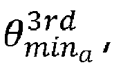
- In addition, it is possible to pre-locate, i.e. narrow down, the possible minimum peak phase angle


- Once the
controller 28 has identified the closest phase angle pairs, i.e. a phase A angle pair


- The
controller 28 is programmed to then determine the first and second proportion factors αabc , βabc by substituting the respective individual estimated angle


- A practical implementation of how the
controller 28 can be programmed to carry out the foregoing steps to establish the first and second proportion factors αabc , βabc is shown schematically inFigure 4 , including seveniterations 36 of the iterative steps mentioned above, although fewer than or greater than seven iterations may be carried out instead. - Once the first and second proportion factors αabc , βabc have been established, the
controller 28 is programmed to equate the first proportion factor αabc and amplitude ρA , ρB, ρC of the corresponding phase A, B, C of the instantaneous phase-to-ground three-phase voltage of the fundamental AC phase voltage reference


- More particularly, the
controller 28 establishes the positive and negative sequence magnitudes |vp |, |vp | as follows


lim is the predetermined amplitude limit, e.g. 1 pu, and
the respective amplitudes ρA , ρB , ρC , ρ 3rd can be expressed in terms of the positive and negative sequence magnitudes |vp |, |vp | in the following manner


- Thereafter, the
controller 28 is programmed to limit the magnitude of the fundamental AC phase voltage reference
Figures 3(a) and3(b) . - Within
Figures 3(a) and3(b) ,


A and K are expressions of each dq component phase angle, the magnitude portion of the positive and negative sequences; and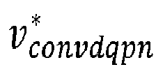

- In addition, the
controller 28 is programmed to extend the elliptic limiting 38 by applying the first proportion factor αa , αb , αc to an elliptic limiting expression and introducing a harmonic limiting expression incorporating the second proportion factor βa , βb , βc , within respective positive and negative limitingexpressions - The resulting limiting
expressions 


- So, for example, the positive limiting
expression 40 for each phase A, B, C is specifically expressed as follows


- The
controller 28 is further programmed to establish the minimum limited magnitude |vlim | amongst all of limited fundamental AC phase voltage references


expressions 40 inFigure 3(b) , thecontroller 28 establishes the minimum limited magnitude |vlim | according to
- Accordingly, by applying the aforementioned extended elliptic limiting, the
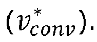
controller 28 produces a limited magnitude version


AC terminal
Claims (11)
- A voltage source converter (10), for transferring power between AC and DC networks, comprising:first and second DC terminals (12, 14) for connection to a DC network and having a plurality of converter limbs (16A, 16B, 16C) extending therebetween, each converter limb (16A, 16B, 16C) including first and second limb portions (18A, 18B, 18C, 20A, 20B, 20C) separated by a corresponding AC terminal (22A, 22B, 22C) for connection to a respective phase (A, B, C) of an AC network, each limb portion (18A, 18B, 18C, 20A, 20B, 20C) including a chain-link converter (24) extending between the associated AC terminal (22A, 22B, 22C) and a corresponding one of the first of the second DC terminals (12, 14), and each chain-link converter (24) including a plurality of series connected chain-link modules (26) each having a plurality of switching elements connected in parallel with an energy storage device, whereby each chain-link converter (24) is controllable to provide a stepped variable voltage source; anda controller (28) programmed to establish for each AC terminal (22A, 22B, 22C) an AC phase voltage demand
 the controller (28) establishing each AC voltage demand
 the controller (28) maintaining each established AC phase voltage demand


- A voltage source converter (10) according to Claim 1 wherein the controller (28) is programmed to establish a first proportion factor (αabc ) corresponding to the expected contribution of the fundamental AC voltage reference

- A voltage source converter (10) according to Claim 2 wherein establishing the first and second proportion factors (αabc , βabc ) includes establishing an anticipated maximum resulting AC voltage demand

- A voltage source converter (10) according to Claim 3 wherein establishing an anticipated maximum resulting AC voltage demand


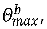
- A voltage source converter (10) according to Claim 4 wherein the controller (28) is programmed to employ an iterative process (36) to estimate the angle (


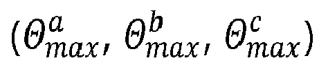
- A voltage source converter (10) according to Claim 5 wherein the controller (28) is programmed to use the estimated angle

- A voltage source converter (10) according to Claim 6 wherein the controller (28) is programmed to equate the first proportion factor (αabc ) and amplitude (ρA , ρB , ρC ) of the fundamental AC voltage reference

- A voltage source converter (10) according to Claim 7 wherein the controller (28) is programmed to limit the magnitude (|vlim |) of the fundamental AC phase voltage reference

- A voltage source converter (10) according to Claim 8 wherein the controller (28) is programmed to extend the elliptic limiting (38) by applying the first proportion factor (αa , αb , αc ) to an elliptic limiting expression and introducing a harmonic limiting expression incorporating the second proportion factor (βa , βb , βc ).
- A voltage source converter (10) according to any preceding claim wherein the controller (28) is programmed to establish the minimum limited magnitude (|vlim |) amongst all of limited fundamental AC phase voltage references


- A method of controlling a voltage source converter (10) including first and second DC terminals (12, 14) for connection to a DC network and having a plurality of converter limbs (16A, 16B, 16C) extending therebetween, each converter limb (16A, 16B, 16C) including first and second limb portions (18A, 18B, 18C, 20A, 20B, 20C) separated by a corresponding AC terminal (""A, 22B, 22C) for connection to a respective phase (A, B, C) of an AC network, each limb portion (18A, 18B, 18C, 20A, 20B, 20C) including a chain-link converter (24) extending between the associated AC terminal (22A, 22B, 22C) and a corresponding one of the first of the second DC terminals (12, 14), and each chain-link converter (24) including a plurality of series connected chain-link modules (26) each having a plurality of switching elements connected in parallel with an energy storage device, whereby each chain-link converter (24) is controllable to provide a stepped variable voltage source,
the method comprising the steps of:(a) establishing for each AC terminal (22A, 22B, 22C) an AC phase voltage demand (b) establishing each AC voltage demand
 (c) maintaining each established AC phase voltage demand


Priority Applications (1)
| Application Number | Priority Date | Filing Date | Title |
|---|---|---|---|
| EP20275159.0A EP3985851B1 (en) | 2020-10-16 | 2020-10-16 | Improvements in or relating to voltage source converters |
Applications Claiming Priority (1)
| Application Number | Priority Date | Filing Date | Title |
|---|---|---|---|
| EP20275159.0A EP3985851B1 (en) | 2020-10-16 | 2020-10-16 | Improvements in or relating to voltage source converters |
Publications (2)
| Publication Number | Publication Date |
|---|---|
| EP3985851A1 true EP3985851A1 (en) | 2022-04-20 |
| EP3985851B1 EP3985851B1 (en) | 2026-03-18 |
Family
ID=72944052
Family Applications (1)
| Application Number | Title | Priority Date | Filing Date |
|---|---|---|---|
| EP20275159.0A Active EP3985851B1 (en) | 2020-10-16 | 2020-10-16 | Improvements in or relating to voltage source converters |
Country Status (1)
| Country | Link |
|---|---|
| EP (1) | EP3985851B1 (en) |
Citations (1)
| Publication number | Priority date | Publication date | Assignee | Title |
|---|---|---|---|---|
| JP2003134843A (en) * | 2001-10-26 | 2003-05-09 | Fuji Electric Co Ltd | Control method for PWM power converter |
-
2020
- 2020-10-16 EP EP20275159.0A patent/EP3985851B1/en active Active
Patent Citations (1)
| Publication number | Priority date | Publication date | Assignee | Title |
|---|---|---|---|---|
| JP2003134843A (en) * | 2001-10-26 | 2003-05-09 | Fuji Electric Co Ltd | Control method for PWM power converter |
Non-Patent Citations (2)
| Title |
|---|
| LI RUI ET AL: "Enhanced Flat-Topped Modulation for MMC Control in HVDC Transmission Systems", IEEE TRANSACTIONS ON POWER DELIVERY, vol. 32, no. 1, February 2017 (2017-02-01), US, pages 152 - 161, XP055788559, ISSN: 0885-8977, DOI: 10.1109/TPWRD.2016.2561929 * |
| LOPEZ MARIO ET AL: "Operation of modular multilevel converters under voltage constraints", 2015 IEEE ENERGY CONVERSION CONGRESS AND EXPOSITION (ECCE), IEEE, 20 September 2015 (2015-09-20), pages 3550 - 3556, XP032801051, DOI: 10.1109/ECCE.2015.7310162 * |
Also Published As
| Publication number | Publication date |
|---|---|
| EP3985851B1 (en) | 2026-03-18 |
Similar Documents
| Publication | Publication Date | Title |
|---|---|---|
| KR101727778B1 (en) | Hybrid HVDC Converter | |
| US10199954B2 (en) | Voltage source converter | |
| US20150003134A1 (en) | Modular multilevel converter using asymmetry | |
| EP2443717B1 (en) | An arrangement for exchanging power | |
| EP2560065A1 (en) | Power converter | |
| CN102820671A (en) | Calculation method for the number of sub-modules in the bridge arm of modular multilevel converter | |
| US20150357901A1 (en) | Voltage source converter | |
| CN105226927A (en) | Circulating current suppression method and system for cascaded multilevel converters | |
| Pei et al. | Improved carrier-based DPWM for Vienna rectifier considering oscillated and unbalanced neutral-point voltages | |
| US12142913B2 (en) | Electrical assembly having a characterized electrical parameter | |
| EP3985851B1 (en) | Improvements in or relating to voltage source converters | |
| WO2016135247A2 (en) | Voltage source converter | |
| US20230335994A1 (en) | Electrical assembly | |
| US20190013742A1 (en) | Voltage source converter | |
| EP3945654B1 (en) | Improvements in or relating to grid-connected power converters | |
| US20240055865A1 (en) | Controller for power electronic device | |
| EP3920388B1 (en) | Improvements in or relating to voltage source converters | |
| US20230062409A1 (en) | Switching valve | |
| EP3382880B1 (en) | Improvements in or relating to the control of voltage source converters | |
| US20260100584A1 (en) | System and method for controlling a power electronics device in a power transmission network | |
| Xu et al. | Direct power control based on renewable energy access for VSC-HVDC system | |
| US20230188027A1 (en) | Improvements in or relating to chain-link modules for voltage source converters | |
| Mahjoub et al. | Modeling of controller for voltage sourced converter based HVDC transmission system | |
| JP2023157541A (en) | Power conversion device and its control method | |
| Chen et al. | Reduction in Quantity of Submodules in UC-FB-MMC by Injecting Zero-Sequence Voltage |
Legal Events
| Date | Code | Title | Description |
|---|---|---|---|
| PUAI | Public reference made under article 153(3) epc to a published international application that has entered the european phase |
Free format text: ORIGINAL CODE: 0009012 |
|
| STAA | Information on the status of an ep patent application or granted ep patent |
Free format text: STATUS: THE APPLICATION HAS BEEN PUBLISHED |
|
| AK | Designated contracting states |
Kind code of ref document: A1 Designated state(s): AL AT BE BG CH CY CZ DE DK EE ES FI FR GB GR HR HU IE IS IT LI LT LU LV MC MK MT NL NO PL PT RO RS SE SI SK SM TR |
|
| STAA | Information on the status of an ep patent application or granted ep patent |
Free format text: STATUS: REQUEST FOR EXAMINATION WAS MADE |
|
| 17P | Request for examination filed |
Effective date: 20221012 |
|
| RBV | Designated contracting states (corrected) |
Designated state(s): AL AT BE BG CH CY CZ DE DK EE ES FI FR GB GR HR HU IE IS IT LI LT LU LV MC MK MT NL NO PL PT RO RS SE SI SK SM TR |
|
| P01 | Opt-out of the competence of the unified patent court (upc) registered |
Effective date: 20230522 |
|
| STAA | Information on the status of an ep patent application or granted ep patent |
Free format text: STATUS: EXAMINATION IS IN PROGRESS |
|
| 17Q | First examination report despatched |
Effective date: 20231206 |
|
| RAP3 | Party data changed (applicant data changed or rights of an application transferred) |
Owner name: GE VERNOVA TECHNOLOGY GMBH |
|
| GRAP | Despatch of communication of intention to grant a patent |
Free format text: ORIGINAL CODE: EPIDOSNIGR1 |
|
| STAA | Information on the status of an ep patent application or granted ep patent |
Free format text: STATUS: GRANT OF PATENT IS INTENDED |
|
| INTG | Intention to grant announced |
Effective date: 20251016 |
|
| RIN1 | Information on inventor provided before grant (corrected) |
Inventor name: LI, JIAQI Inventor name: DE PREVILLE, GUILLAUME Inventor name: FREYTES, JULIAN |
|
| GRAS | Grant fee paid |
Free format text: ORIGINAL CODE: EPIDOSNIGR3 |
|
| GRAA | (expected) grant |
Free format text: ORIGINAL CODE: 0009210 |
|
| STAA | Information on the status of an ep patent application or granted ep patent |
Free format text: STATUS: THE PATENT HAS BEEN GRANTED |
|
| AK | Designated contracting states |
Kind code of ref document: B1 Designated state(s): AL AT BE BG CH CY CZ DE DK EE ES FI FR GB GR HR HU IE IS IT LI LT LU LV MC MK MT NL NO PL PT RO RS SE SI SK SM TR |
|
| REG | Reference to a national code |
Ref country code: CH Ref legal event code: F10 Free format text: ST27 STATUS EVENT CODE: U-0-0-F10-F00 (AS PROVIDED BY THE NATIONAL OFFICE) Effective date: 20260318 Ref country code: GB Ref legal event code: FG4D |
|
| REG | Reference to a national code |
Ref country code: IE Ref legal event code: FG4D |
|
| REG | Reference to a national code |
Ref country code: DE Ref legal event code: R096 Ref document number: 602020068740 Country of ref document: DE |
|
| REG | Reference to a national code |
Ref country code: NL Ref legal event code: FP |
|
| PG25 | Lapsed in a contracting state [announced via postgrant information from national office to epo] |
Ref country code: RS Free format text: LAPSE BECAUSE OF FAILURE TO SUBMIT A TRANSLATION OF THE DESCRIPTION OR TO PAY THE FEE WITHIN THE PRESCRIBED TIME-LIMIT Effective date: 20260618 |
|
| PG25 | Lapsed in a contracting state [announced via postgrant information from national office to epo] |
Ref country code: GR Free format text: LAPSE BECAUSE OF FAILURE TO SUBMIT A TRANSLATION OF THE DESCRIPTION OR TO PAY THE FEE WITHIN THE PRESCRIBED TIME-LIMIT Effective date: 20260619 |
|
| REG | Reference to a national code |
Ref country code: LT Ref legal event code: MG9D |
|
| PG25 | Lapsed in a contracting state [announced via postgrant information from national office to epo] |
Ref country code: LT Free format text: LAPSE BECAUSE OF FAILURE TO SUBMIT A TRANSLATION OF THE DESCRIPTION OR TO PAY THE FEE WITHIN THE PRESCRIBED TIME-LIMIT Effective date: 20260318 |
|
| PG25 | Lapsed in a contracting state [announced via postgrant information from national office to epo] |
Ref country code: NO Free format text: LAPSE BECAUSE OF FAILURE TO SUBMIT A TRANSLATION OF THE DESCRIPTION OR TO PAY THE FEE WITHIN THE PRESCRIBED TIME-LIMIT Effective date: 20260618 |
|
| PG25 | Lapsed in a contracting state [announced via postgrant information from national office to epo] |
Ref country code: FI Free format text: LAPSE BECAUSE OF FAILURE TO SUBMIT A TRANSLATION OF THE DESCRIPTION OR TO PAY THE FEE WITHIN THE PRESCRIBED TIME-LIMIT Effective date: 20260318 |
|
| PG25 | Lapsed in a contracting state [announced via postgrant information from national office to epo] |
Ref country code: HR Free format text: LAPSE BECAUSE OF FAILURE TO SUBMIT A TRANSLATION OF THE DESCRIPTION OR TO PAY THE FEE WITHIN THE PRESCRIBED TIME-LIMIT Effective date: 20260318 |
|
| PG25 | Lapsed in a contracting state [announced via postgrant information from national office to epo] |
Ref country code: LV Free format text: LAPSE BECAUSE OF FAILURE TO SUBMIT A TRANSLATION OF THE DESCRIPTION OR TO PAY THE FEE WITHIN THE PRESCRIBED TIME-LIMIT Effective date: 20260318 |
|
| PG25 | Lapsed in a contracting state [announced via postgrant information from national office to epo] |
Ref country code: BG Free format text: LAPSE BECAUSE OF FAILURE TO SUBMIT A TRANSLATION OF THE DESCRIPTION OR TO PAY THE FEE WITHIN THE PRESCRIBED TIME-LIMIT Effective date: 20260318 |