EP3985784A1 - A battery for an aircraft - Google Patents
A battery for an aircraft Download PDFInfo
- Publication number
- EP3985784A1 EP3985784A1 EP20400018.6A EP20400018A EP3985784A1 EP 3985784 A1 EP3985784 A1 EP 3985784A1 EP 20400018 A EP20400018 A EP 20400018A EP 3985784 A1 EP3985784 A1 EP 3985784A1
- Authority
- EP
- European Patent Office
- Prior art keywords
- battery
- fibrous mat
- casing
- intumescent material
- functional layer
- Prior art date
- Legal status (The legal status is an assumption and is not a legal conclusion. Google has not performed a legal analysis and makes no representation as to the accuracy of the status listed.)
- Pending
Links
Images






Classifications
-
- H—ELECTRICITY
- H01—ELECTRIC ELEMENTS
- H01M—PROCESSES OR MEANS, e.g. BATTERIES, FOR THE DIRECT CONVERSION OF CHEMICAL ENERGY INTO ELECTRICAL ENERGY
- H01M50/00—Constructional details or processes of manufacture of the non-active parts of electrochemical cells other than fuel cells, e.g. hybrid cells
- H01M50/20—Mountings; Secondary casings or frames; Racks, modules or packs; Suspension devices; Shock absorbers; Transport or carrying devices; Holders
- H01M50/249—Mountings; Secondary casings or frames; Racks, modules or packs; Suspension devices; Shock absorbers; Transport or carrying devices; Holders specially adapted for aircraft or vehicles, e.g. cars or trains
-
- H—ELECTRICITY
- H01—ELECTRIC ELEMENTS
- H01M—PROCESSES OR MEANS, e.g. BATTERIES, FOR THE DIRECT CONVERSION OF CHEMICAL ENERGY INTO ELECTRICAL ENERGY
- H01M50/00—Constructional details or processes of manufacture of the non-active parts of electrochemical cells other than fuel cells, e.g. hybrid cells
- H01M50/10—Primary casings; Jackets or wrappings
- H01M50/116—Primary casings; Jackets or wrappings characterised by the material
- H01M50/124—Primary casings; Jackets or wrappings characterised by the material having a layered structure
- H01M50/1243—Primary casings; Jackets or wrappings characterised by the material having a layered structure characterised by the internal coating on the casing
-
- H—ELECTRICITY
- H01—ELECTRIC ELEMENTS
- H01M—PROCESSES OR MEANS, e.g. BATTERIES, FOR THE DIRECT CONVERSION OF CHEMICAL ENERGY INTO ELECTRICAL ENERGY
- H01M50/00—Constructional details or processes of manufacture of the non-active parts of electrochemical cells other than fuel cells, e.g. hybrid cells
- H01M50/20—Mountings; Secondary casings or frames; Racks, modules or packs; Suspension devices; Shock absorbers; Transport or carrying devices; Holders
- H01M50/218—Mountings; Secondary casings or frames; Racks, modules or packs; Suspension devices; Shock absorbers; Transport or carrying devices; Holders characterised by the material
- H01M50/22—Mountings; Secondary casings or frames; Racks, modules or packs; Suspension devices; Shock absorbers; Transport or carrying devices; Holders characterised by the material of the casings or racks
- H01M50/231—Mountings; Secondary casings or frames; Racks, modules or packs; Suspension devices; Shock absorbers; Transport or carrying devices; Holders characterised by the material of the casings or racks having a layered structure
-
- B—PERFORMING OPERATIONS; TRANSPORTING
- B64—AIRCRAFT; AVIATION; COSMONAUTICS
- B64D—EQUIPMENT FOR FITTING IN OR TO AIRCRAFT; FLIGHT SUITS; PARACHUTES; ARRANGEMENT OR MOUNTING OF POWER PLANTS OR PROPULSION TRANSMISSIONS IN AIRCRAFT
- B64D41/00—Power installations for auxiliary purposes
-
- H—ELECTRICITY
- H01—ELECTRIC ELEMENTS
- H01M—PROCESSES OR MEANS, e.g. BATTERIES, FOR THE DIRECT CONVERSION OF CHEMICAL ENERGY INTO ELECTRICAL ENERGY
- H01M10/00—Secondary cells; Manufacture thereof
- H01M10/05—Accumulators with non-aqueous electrolyte
- H01M10/052—Li-accumulators
- H01M10/0525—Rocking-chair batteries, i.e. batteries with lithium insertion or intercalation in both electrodes; Lithium-ion batteries
-
- H—ELECTRICITY
- H01—ELECTRIC ELEMENTS
- H01M—PROCESSES OR MEANS, e.g. BATTERIES, FOR THE DIRECT CONVERSION OF CHEMICAL ENERGY INTO ELECTRICAL ENERGY
- H01M10/00—Secondary cells; Manufacture thereof
- H01M10/05—Accumulators with non-aqueous electrolyte
- H01M10/054—Accumulators with insertion or intercalation of metals other than lithium, e.g. with magnesium or aluminium
-
- H—ELECTRICITY
- H01—ELECTRIC ELEMENTS
- H01M—PROCESSES OR MEANS, e.g. BATTERIES, FOR THE DIRECT CONVERSION OF CHEMICAL ENERGY INTO ELECTRICAL ENERGY
- H01M50/00—Constructional details or processes of manufacture of the non-active parts of electrochemical cells other than fuel cells, e.g. hybrid cells
- H01M50/10—Primary casings; Jackets or wrappings
- H01M50/116—Primary casings; Jackets or wrappings characterised by the material
- H01M50/122—Composite material consisting of a mixture of organic and inorganic materials
-
- H—ELECTRICITY
- H01—ELECTRIC ELEMENTS
- H01M—PROCESSES OR MEANS, e.g. BATTERIES, FOR THE DIRECT CONVERSION OF CHEMICAL ENERGY INTO ELECTRICAL ENERGY
- H01M50/00—Constructional details or processes of manufacture of the non-active parts of electrochemical cells other than fuel cells, e.g. hybrid cells
- H01M50/10—Primary casings; Jackets or wrappings
- H01M50/116—Primary casings; Jackets or wrappings characterised by the material
- H01M50/124—Primary casings; Jackets or wrappings characterised by the material having a layered structure
-
- H—ELECTRICITY
- H01—ELECTRIC ELEMENTS
- H01M—PROCESSES OR MEANS, e.g. BATTERIES, FOR THE DIRECT CONVERSION OF CHEMICAL ENERGY INTO ELECTRICAL ENERGY
- H01M50/00—Constructional details or processes of manufacture of the non-active parts of electrochemical cells other than fuel cells, e.g. hybrid cells
- H01M50/10—Primary casings; Jackets or wrappings
- H01M50/116—Primary casings; Jackets or wrappings characterised by the material
- H01M50/124—Primary casings; Jackets or wrappings characterised by the material having a layered structure
- H01M50/126—Primary casings; Jackets or wrappings characterised by the material having a layered structure comprising three or more layers
-
- H—ELECTRICITY
- H01—ELECTRIC ELEMENTS
- H01M—PROCESSES OR MEANS, e.g. BATTERIES, FOR THE DIRECT CONVERSION OF CHEMICAL ENERGY INTO ELECTRICAL ENERGY
- H01M50/00—Constructional details or processes of manufacture of the non-active parts of electrochemical cells other than fuel cells, e.g. hybrid cells
- H01M50/10—Primary casings; Jackets or wrappings
- H01M50/14—Primary casings; Jackets or wrappings for protecting against damage caused by external factors
-
- H—ELECTRICITY
- H01—ELECTRIC ELEMENTS
- H01M—PROCESSES OR MEANS, e.g. BATTERIES, FOR THE DIRECT CONVERSION OF CHEMICAL ENERGY INTO ELECTRICAL ENERGY
- H01M50/00—Constructional details or processes of manufacture of the non-active parts of electrochemical cells other than fuel cells, e.g. hybrid cells
- H01M50/10—Primary casings; Jackets or wrappings
- H01M50/14—Primary casings; Jackets or wrappings for protecting against damage caused by external factors
- H01M50/143—Fireproof; Explosion-proof
-
- H—ELECTRICITY
- H01—ELECTRIC ELEMENTS
- H01M—PROCESSES OR MEANS, e.g. BATTERIES, FOR THE DIRECT CONVERSION OF CHEMICAL ENERGY INTO ELECTRICAL ENERGY
- H01M50/00—Constructional details or processes of manufacture of the non-active parts of electrochemical cells other than fuel cells, e.g. hybrid cells
- H01M50/20—Mountings; Secondary casings or frames; Racks, modules or packs; Suspension devices; Shock absorbers; Transport or carrying devices; Holders
- H01M50/204—Racks, modules or packs for multiple batteries or multiple cells
- H01M50/207—Racks, modules or packs for multiple batteries or multiple cells characterised by their shape
- H01M50/213—Racks, modules or packs for multiple batteries or multiple cells characterised by their shape adapted for cells having curved cross-section, e.g. round or elliptic
-
- H—ELECTRICITY
- H01—ELECTRIC ELEMENTS
- H01M—PROCESSES OR MEANS, e.g. BATTERIES, FOR THE DIRECT CONVERSION OF CHEMICAL ENERGY INTO ELECTRICAL ENERGY
- H01M50/00—Constructional details or processes of manufacture of the non-active parts of electrochemical cells other than fuel cells, e.g. hybrid cells
- H01M50/20—Mountings; Secondary casings or frames; Racks, modules or packs; Suspension devices; Shock absorbers; Transport or carrying devices; Holders
- H01M50/233—Mountings; Secondary casings or frames; Racks, modules or packs; Suspension devices; Shock absorbers; Transport or carrying devices; Holders characterised by physical properties of casings or racks, e.g. dimensions
- H01M50/24—Mountings; Secondary casings or frames; Racks, modules or packs; Suspension devices; Shock absorbers; Transport or carrying devices; Holders characterised by physical properties of casings or racks, e.g. dimensions adapted for protecting batteries from their environment, e.g. from corrosion
-
- H—ELECTRICITY
- H01—ELECTRIC ELEMENTS
- H01M—PROCESSES OR MEANS, e.g. BATTERIES, FOR THE DIRECT CONVERSION OF CHEMICAL ENERGY INTO ELECTRICAL ENERGY
- H01M50/00—Constructional details or processes of manufacture of the non-active parts of electrochemical cells other than fuel cells, e.g. hybrid cells
- H01M50/30—Arrangements for facilitating escape of gases
-
- H—ELECTRICITY
- H01—ELECTRIC ELEMENTS
- H01M—PROCESSES OR MEANS, e.g. BATTERIES, FOR THE DIRECT CONVERSION OF CHEMICAL ENERGY INTO ELECTRICAL ENERGY
- H01M50/00—Constructional details or processes of manufacture of the non-active parts of electrochemical cells other than fuel cells, e.g. hybrid cells
- H01M50/30—Arrangements for facilitating escape of gases
- H01M50/35—Gas exhaust passages comprising elongated, tortuous or labyrinth-shaped exhaust passages
- H01M50/358—External gas exhaust passages located on the battery cover or case
-
- H—ELECTRICITY
- H01—ELECTRIC ELEMENTS
- H01M—PROCESSES OR MEANS, e.g. BATTERIES, FOR THE DIRECT CONVERSION OF CHEMICAL ENERGY INTO ELECTRICAL ENERGY
- H01M2200/00—Safety devices for primary or secondary batteries
- H01M2200/10—Temperature sensitive devices
-
- H—ELECTRICITY
- H01—ELECTRIC ELEMENTS
- H01M—PROCESSES OR MEANS, e.g. BATTERIES, FOR THE DIRECT CONVERSION OF CHEMICAL ENERGY INTO ELECTRICAL ENERGY
- H01M2220/00—Batteries for particular applications
- H01M2220/20—Batteries in motive systems, e.g. vehicle, ship, plane
-
- Y—GENERAL TAGGING OF NEW TECHNOLOGICAL DEVELOPMENTS; GENERAL TAGGING OF CROSS-SECTIONAL TECHNOLOGIES SPANNING OVER SEVERAL SECTIONS OF THE IPC; TECHNICAL SUBJECTS COVERED BY FORMER USPC CROSS-REFERENCE ART COLLECTIONS [XRACs] AND DIGESTS
- Y02—TECHNOLOGIES OR APPLICATIONS FOR MITIGATION OR ADAPTATION AGAINST CLIMATE CHANGE
- Y02E—REDUCTION OF GREENHOUSE GAS [GHG] EMISSIONS, RELATED TO ENERGY GENERATION, TRANSMISSION OR DISTRIBUTION
- Y02E60/00—Enabling technologies; Technologies with a potential or indirect contribution to GHG emissions mitigation
- Y02E60/10—Energy storage using batteries
Definitions
- the present embodiments relate to a battery for an aircraft, and, more particularly, to a battery for an aircraft that is adapted to limit the consequences of a breach of the battery's casing.
- the present embodiments further relate to an aircraft with at least one battery that is adapted to limit the consequences of a breach of the battery's casing.
- lithium type batteries i.e., lithium batteries and lithium-ion batteries
- lithium type batteries are currently used to some limited extent in aerospace applications.
- lithium type batteries are considered as the main technology for future electrification of aircrafts, in particular for high-energy and/or high-power applications.
- lithium type batteries use electrolytes, that are known to be flammable.
- a self-sustaining increase in temperature and pressure which is sometimes also referred to as a thermal runaway, may occur.
- the battery casing usually made of stainless steel, can be breached and toxic, hot, flammable, and/or corrosive fluids or gases including the flammable electrolyte and/or other material components of the lithium type battery may be released.
- high temperatures and/or fire may be released from the battery casing. This is particularly hazardous when lithium type batteries are used in vehicles as surrounding vehicle structures or adjacent equipment may be damaged.
- the negative effects of an internal failure of a battery are managed by the battery casing and a gas evacuation provision that vents hot gases overboard in a controlled manner.
- the gas evacuation provision may prevent an increase in pressure inside the battery casing, thereby preventing an explosion of the battery.
- Some traditional mitigation techniques include the use of bullet-resistant and/or bulletproof armor protections around the battery that help to absorb and/or stop the penetration of external impacts caused by bullets or other ballistic threats. These bullet-resistant or bulletproof armor protections comprise many layers of woven or laminated fibers, or metal or ceramic plates. However, all these traditional mitigation techniques have the disadvantage of requiring a significant additional weight, which is unfavorable for some applications such as aerospace applications.
- a polymeric functional material such as ionomer may close a hole created by a ballistic impact.
- Document WO 2012/166494 A1 describes a system with one or more self-sealing panels and a cap member.
- the one or more self-sealing panels substantially cover an exterior surface of a liquid container.
- the cap member covers at least one of the following: one or more portions of the exterior surface of the liquid container; and an exterior surface of at least one of the one or more self-sealing panels.
- the self-sealing material may be combined with multiple filler materials that assist the polymer to keep its functionality.
- the battery comprises a housing that includes a self-sealing ionomer material and that is filled with a material that suppresses flames and/or prevents the internal temperature from reaching an ignition point.
- the self-sealing property is still provided by the self-sealing ionomer alone.
- the fillers only act as flame retardant and/or to prevent the internal temperature from reaching an ignition point or as a mechanical stabilization.
- intumescent materials are typically used in construction as passive fire protection of structural steel as well as firestop to avoid fire propagation.
- intumescent material with lithium batteries is also already known.
- a layer of intumescent material may be used between the casing and the battery for mitigating the propagation of heat to others battery compartments and/or to the car structure.
- Document WO 2015/113133 A1 describes a battery housing comprising a body and a lid, providing a chamber dimensioned to hold at least one battery, and a venting passageway from the chamber.
- a portion of the body and the housing comprises an intumescent material with an expansion ratio sufficient to drive gas from the chamber through the venting passageway and to seal the chamber, when the material intumesces in the event of thermal runaway of a battery housed in the chamber.
- the body and the lid provide a plurality of battery chambers, each dimensioned to hold at least one battery, and a plurality of venting passageways, each venting passageway extending from one battery chamber of the plurality of battery chambers.
- a portion of the body and the lid comprises an intumescent flame-retardant material with an expansion ratio sufficient to drive gas from any given battery chamber of the plurality of battery chambers through at least one of the plurality of venting passageways, and seal the given battery chamber, when the material intumesces in the event of thermal runaway of a battery housed in the given battery chamber.
- a battery for an aircraft may comprise a battery casing with a casing wall that forms an interior volume; a plurality of battery cells that is arranged in the interior volume; and a functional layer that is arranged at the casing wall between the plurality of battery cells and the battery casing, wherein the functional layer comprises an intumescent material that, in case of a breach of the battery casing, is adapted to ensuring flame containment within the interior volume and mitigation of uncontrolled heat and gas emission from the interior volume through the breach of the battery casing.
- the functional layer may be provided in lithium-type batteries used in aircrafts such as airplanes, helicopters, or drones.
- the functional layer may not protect from a ballistic effect. In fact, a bullet may still penetrate the battery casing and damage the battery cells inside the battery casing.
- the functional layer may restore the containment capabilities of the breached battery casing by creating a fireproof and thermally insulating barrier between the battery cells and the battery casing. Furthermore, the fireproof and thermally insulating barrier may close the bullet hole and prevent gases from leaking out of the battery casing in an uncontrolled manner. Thus, the functional layer adds fail-safe characteristics to the battery in a way that hazardous gases and fire are still contained inside the battery casing even though the actual battery casing is damaged.
- the functional layer may close the bullet hole and force hot exhaust gases through a designed gas evacuation venting tube in a controlled manner during a thermal runaway of the damaged battery cells.
- the functional layer of the presented battery has relatively low weight, which is particularly beneficial for the use of such batteries on aircrafts, such as airplanes, helicopters, or drones.
- traditional ballistic protection means such as bullet-resistant or bulletproof armor may weigh between 40kg/m 2 and 45kg/m 2 , whereby all faces of the batteries need to be protected.
- the installation of ballistic protection for the battery may be omitted.
- no integration devices such as fixation points, mountings, supporting frames, or brackets are required.
- the functional layer is integrated into the battery by the equipment manufacturer, resulting in reduced integration time, reduced weight, more available space, and reduced overall cost for the installation in the aircraft.
- the present battery uses a single functional layer to achieve thermal protection, fire proofing, and the ability of sealing a damaged battery casing.
- the above mentioned functionalities may be supported or further enhanced by a multilayer approach.
- the plurality of battery cells comprises at least one of lithium-ion type, sodium-ion type, or magnesium-ion type battery cells.
- the battery further comprises a gas evacuation venting tube that is adapted to enabling a controlled evacuation of gases in case of a thermal runaway of at least a portion of the plurality of battery cells.
- the battery further comprises a structural support layer that encloses the plurality of battery cells and separates the plurality of battery cells from the functional layer.
- the functional layer increases in volume upon intumescence of the intumescent material by at least a factor of 3.
- the functional layer further comprises a fibrous mat that comprises the intumescent material, wherein the fibrous mat remains evenly distributed in a predetermined arrangement between the structural support layer and the casing wall in case of an exposure to a temperature that is below a predetermined threshold, and wherein the fibrous mat is free to move between the structural support layer and the casing wall in case of an exposure to a temperature that is equal to or above the predetermined threshold.
- the fibrous mat comprises at least one of mineral wool, glass fibers, mineral fibers, alkaline earth silica fibers, carbon fibers, basalt fibers, binder, methylol melamine, phenol-formaldehyde resin, epoxy resin, pentaerythritol, monomer, dimer, trimer, starch, dextrin, sorbitol, mannitol, expandable graphite, exfoliating graphite, or char former polymer.
- the fibrous mat is at least partially shaped in a corrugated way with a predetermined height and a predetermined distance between parallel folding lines.
- the ratio between the predetermined height and the predetermined distance is between 0.5 and 5.
- the fibrous mat is superficially cut along the ridges of the parallel folding lines.
- the intumescent mat can be accumulated in one specific part of the battery housing.
- the functional layer further comprises stabilizing means for keeping the fibrous mat evenly distributed in the predetermined arrangement between the structural support layer and the casing wall in case of the exposure to the temperature that is below the predetermined threshold.
- the stabilizing means comprise at least one of pins, rods, or wires.
- the fibrous mat is threaded onto the at least one of pins, rods, or wires.
- the functional layer further comprises an additional intumescent material that forms a coating on the casing wall.
- the intumescent material can be triggered electrically by a resistive heating device.
- an additional intumescent coating can be applied on the (intumescent or not) fibrous mat to form the functional layer.
- an additional polymer coating can be applied on the intumescent fibrous mat to form the functional layer.
- an aircraft may comprise at least one battery as described above.
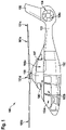
- FIG. 1 shows an example of a transportation vehicle.
- a transportation vehicle may be a spacecraft, an aircraft, a car, a bus, a truck, or a train, just to name a few.
- the transportation vehicle may be an aircraft 100 that is exemplarily illustrated as a rotary-wing aircraft 100, and, more particularly, as a helicopter.
- helicopter 100 the rotary wing aircraft 100 is hereinafter referred to as the "helicopter 100".
- the present invention is, however, not limited to helicopters and can likewise be applied to any other vehicle, in particular to vehicles with at least one battery.
- the helicopter 100 comprises at least one multi-blade main rotor 101a for providing lift and forward or backward thrust during operation.
- the at least one multi-blade main rotor 101a preferentially comprises a plurality of rotor blades 101b, 101c that are mounted at an associated rotor head 101d to a rotor shaft, which rotates in operation of the helicopter 100 around an associated rotor axis.
- the helicopter 100 illustratively further comprises a tail boom 103 and at least one preferentially shrouded counter-torque device 104 configured to provide counter-torque during operation, i.e. to counter the torque created by rotation of the at least one multi-blade main rotor 101a for purposes of balancing the helicopter 100 in terms of yaw.
- the at least one counter-torque device 104 is illustratively provided at an aft section of the tail boom 103 and preferably comprises a tail rotor 104a.
- the aft section of the tail boom 103 preferably further comprises a fin 105.
- Helicopter 100 may have an aircraft airframe 102.
- the tail boom 103 may be connected to the fuselage 102 of the helicopter 100.
- the aircraft airframe 102 defines a supporting structure of helicopter 100 that is also referred to hereinafter as the fuselage 102 of the helicopter 100.
- fuselage 102 forms an aircraft interior region 102a, 102b.
- the aircraft interior region 102a, 102b preferably accommodates at least a cockpit 102a and may further accommodate a cabin 102b.
- the cabin 102b may be adapted for the transportation of passengers and/or cargo, so that the rotary-wing aircraft 100 as a whole is adapted for the transportation of passengers. If desired, the cabin 102b may be adapted for accommodating operational and electrical equipment, such as e.g. a battery.
- operational and electrical equipment such as e.g. a battery.
- exemplary configurations of the cabin 102b that are suitable for the transportation of passengers, but also for the accommodation of operational and electrical equipment, are readily available to the person skilled in the art and generally implemented to comply with applicable authority regulations and certification requirements regarding passenger transportation. Thus, these configurations of the cabin 102b are not described in detail for brevity and conciseness.
- the helicopter 100 may include an aircraft upper deck 106 and that illustratively forms an engine accommodating region 107.
- the aircraft upper deck 106 and, more particularly, at least the engine deck 106a is covered by a cowling 108 that is mounted on top of the fuselage 102.
- a battery may be installed in the engine accommodating region 107. If desired, the battery may be a battery as described in Figure 2.
- Figure 2 is a diagram of an illustrative battery 200 with a battery casing 210 and a plurality of battery cells 220 in accordance with some embodiments.
- the battery casing 210 may comprise a casing wall 215 and form an interior volume 217.
- the plurality of battery cells 220 is arranged in the interior volume 217.
- the plurality of battery cells 220 may include at least one of lithium-ion type, sodium-ion type, or magnesium-ion type battery cells.
- the battery 200 may include a gas evacuation venting tube 240.
- the gas evacuation venting tube 240 may be adapted to enabling a controlled evacuation of gases, for example in case of a thermal runaway of at least a portion of the plurality of battery cells 220.
- the battery 200 may include a functional layer.
- the functional layer may be arranged at the casing wall 215 between the plurality of battery cells 220 and the battery casing 210.
- the functional layer may include an intumescent material.
- the intumescent material may be adapted to ensuring flame containment within the interior volume 217 and mitigation of uncontrolled heat and gas emission 352 from the interior volume 217 through the breach of the battery casing 220.
- the intumescent material may intumesce into an expanded char that provides a thermal insulation between the plurality of battery cells 220 and the casing wall 215 and closes the breach of the battery casing 210.
- Figure 3A is a diagram of an illustrative battery 200 with battery cells 220, a battery casing 210, a functional layer 330, and a gas evacuation venting tube 240 in accordance with some embodiments.
- the functional layer 330 may be arranged at the casing wall 215.
- the functional layer 330 may cover the entire interior surface of the casing wall 215.
- the functional layer 330 may include an intumescent material 335.
- the intumescent material 335 may swell up and form an expanded char in case of an exposure to a temperature that is above a predetermined temperature threshold.
- any fire inside the interior volume 217 may expose the intumescent material 335 to a temperature that is above the predetermined temperature threshold, thereby leading to the intumescence of the intumescent material 335.
- a damage event that breaches the battery casing 210 and damages one or more battery cells of the plurality of battery cells 220 may cause a thermal runaway of the one or more damaged battery cells that leads to a fire. Due to the fire, the intumescent material 335 may be exposed to a temperature above the predetermined temperature threshold and lead to the intumescence of the intumescent material 335.
- Figure 3B is a diagram of the illustrative battery 200 of Figure 3A after a breach 340 of the battery casing 210 that is followed by a thermal runaway of the battery cells 220 in accordance with some embodiments.
- any impact on the battery casing 210 may result in a breach 340 of the battery casing 210.
- the battery casing 210 may not move and be hit by flying debris, a bullet, shrapnel, or any other moving object.
- the battery casing 210 may move and hit other equipment, the floor, or any other non-moving object.
- the battery casing 210 may move and be hit by another moving object.
- the functional layer 330 may increase in volume upon intumescence of the intumescent material by at least a factor of 2.
- the functional layer 330 may increase in volume upon intumescence of the intumescent material by at least a factor of 3.
- the functional layer 330 may increase in volume upon intumescence of the intumescent material by more than a factor of 4,
- the expanded char 337 from the intumescent material after intumescence may have a lower thermal conductivity than the intumescent material before intumescence.
- the expanded char 337 may form a plug 355 that closes the breach 340.
- the functional layer 330 with the intumescent material after intumescence may form an airtight or gas flow or convection barrier at the breach 340.
- the functional layer 330 may prevent flames and/or flammable gases from leaking through the breach 340.
- the expanded char 337 (i.e., the intumescent material after intumescence) may be adapted to ensuring flame containment within the interior volume 217 and mitigation of uncontrolled heat and gas emission from the interior volume 217 through the breach 340 of the battery casing 210. If desired, heat and gases 350 may be released through the gas evacuation venting tube 240 that is adapted to enabling the controlled evacuation of gases 350.
- a structural support layer may be provided.
- the structural support layer may assist with the arrangement of the functional layer 330 at the casing wall 215.
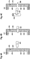
- FIG 4A is a diagram of an illustrative battery with a functional layer 330 in accordance with some embodiments.
- the functional layer 330 may include an intumescent material 335 and be arranged between a battery casing 210 that forms an interior volume 217 and a structural support layer 470.
- the illustrative battery is shown before being hit by a bullet 420.
- the structural support layer 470 may enclose a battery cell. If desired, the structural support layer 470 may enclose a plurality of battery cells. For example, the structural support layer 470 may separate the plurality of battery cells from the functional layer 330.
- the functional layer 330 may include a fibrous mat that comprises the intumescent material 335. If desired, the functional layer 330 may include an additional intumescent material. The additional intumescent material may form a coating on the casing wall 215.
- Figure 4B is a diagram of the illustrative battery of Figure 4A with the bullet 420 hitting the battery casing 210 in accordance with some embodiments.
- the bullet 420 may damage the casing wall 215, the functional layer 330, and the structural support layer 470.
- the velocity and the caliber of the bullet 420 may enable the bullet 420 to puncture the casing wall 215, the functional layer 330, and the structural support layer 470, thereby forming a breach of the battery casing 210.
- the bullet 420 may hit one or more of the plurality of battery cells inside the battery casing 210.
- Figure 4C is a diagram of the illustrative battery of Figure 4B in which the bullet 420 reaches and damages a battery cell 220 in accordance with some embodiments.
- the damaged battery cell 220 may become unstable.
- the damaged battery cell 220 may experience a thermal runaway and/or leak and release flammable, toxic, and/or corrosive gases.
- the damaged battery cell 220 may damage other battery cells 220 that were not damaged by the bullet.
- Figure 4D is a diagram of the illustrative battery of Figure 4C in which the damaged battery cell 220 experiences a thermal runaway 360 that causes a fire with uncontrolled heat and gas emissions 352.
- the fire may lead to an increase in temperature of the functional layer 330.
- the intumescent material 335 may intumesce.
- Figure 4E is a diagram of the illustrative battery of Figure 4D in which the functional layer 330 increases in volume upon intumescence of the intumescent material 335.
- the expanded char 337 that results from the intumescence of the intumescent material 335 may fill the majority of space between the structural support layer 470 and the casing wall 215 of the battery casing 210.
- the expanded char 337 may form a plug 355 that closes the breach 340 created by the bullet. Thereby, the expanded char 337 may ensure flame containment within the interior volume 217.
- the expanded char 337 may mitigate uncontrolled heat release from the interior volume 217.
- the expanded char 337 may ensure the safety of the equipment that surrounds the battery.
- the intumescent material 335 may be coated onto the casing wall 215 of the battery casing 210.
- a fibrous mat may include intumescent material.
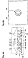
- Figure 5A is a diagram of a battery with a functional layer 330 that includes an illustrative fibrous mat 530 with an intumescent material 335 before intumescence.
- the fibrous mat 530 may remain evenly distributed in a predetermined arrangement between the structural support layer 470 and the casing wall 215 of the battery casing 210 in case of an exposure to a temperature that is below a predetermined threshold.
- the fibrous mat 530 may remain evenly distributed in the predetermined arrangement between the structural support layer 470 and the casing wall 215 in case of an exposure to a temperature that is below the temperature that leads to the intumescence of the intumescent material 335.
- the fibrous mat 530 may be free to move between the structural support layer 470 and the casing wall 215 in case of an exposure to a temperature that is equal to or above the predetermined threshold.
- the fibrous mat 530 may be free to move between the structural support layer 470 and the casing wall 215 in case of an exposure to a temperature that is equal to or above the temperature that leads to the intumescence of the intumescent material 335.
- the fibrous mat 530 may include at least one of mineral wool, glass fibers, mineral fibers, alkaline earth silica fibers, carbon fibers, basalt fibers, binder, methylol melamine, phenol-formaldehyde resin, epoxy resin, pentaerythritol, monomer, dimer, trimer, starch, dextrin, sorbitol, mannitol, expandable graphite, exfoliating graphite, or char former polymer.
- the fibrous mat 530 may be at least partially shaped in a corrugated way with a predetermined height 532 and a predetermined distance 534 between parallel folding lines 536.
- the wrinkles of the fibrous mat 530 may be oriented parallel to the direction from which a damaging event is expected to approach the battery casing 210.
- the wrinkles of the fibrous mat 530 may be parallel to the normal direction of the adjacent surface of the casing wall 215 of the battery casing 210.
- the ratio between the predetermined height 532 and the predetermined distance 534 may be between 0.2 and 10.
- the ratio between the predetermined height 532 and the predetermined distance 534 may be between 0.5 and 5.
- the predetermined height 532 may be 25mm and the predetermined distance 534 12.5mm, resulting in a ratio of 2 between the predetermined height 532 and the predetermined distance 534.
- the predetermined height 532 may be 25mm and the predetermined distance 534 21.3mm, resulting in a ratio of approximately 1.17 between the predetermined height 532 and the predetermined distance 534.
- the fibrous mat 530 may be superficially cut along the ridges of the parallel folding lines 536.
- the fibrous mat 530 may be superficially cut along the ridges of the parallel folding lines 536 to ease folding of the fibrous mat 530 and/or to reduce the spring effect of the folded fibrous mat 530.
- Figure 5B is a diagram of the illustrative battery casing of Figure 5A seen from above
- Figure 5C is a diagram of a bullet traversing both the fibrous mat 530 and the battery casing 210 of Figure 5A in accordance with some embodiments.
- the bullet may hit and damage one or more battery cells, which may lead to a fire inside the battery casing 210.
- the temperature inside the battery casing 210 may exceed the predetermined temperature threshold, above which the intumescent material 335 in the fibrous mat 530 intumesces.
- the fibrous mat 530 may increase in volume between the structural support layer and the battery casing 210.
- the intumescent material 335 in the fibrous mat 530 may lead to the closure of the hole in the fibrous mat 530 caused by the bullet. Thereby, the intumescent material 335 in the fibrous mat 530 may ensure flame containment within the battery casing 210 and/or mitigation of uncontrolled heat and gas emission from the battery casing.
- Figure 5D is a diagram of the illustrative fibrous mat 530 of Figure 5C after traversal of the bullet and ensuing intumescence of the intumescent material 335 seen from the side of the battery casing 210.
- Figure 5E is a diagram of the illustrative fibrous mat 530 of Figure 5C after traversal of the bullet and ensuing intumescence of the intumescent material 335 seen from the side of the structural support layer 470 in accordance with some embodiments.
- intumescent material 335 completely closes the hole in the fibrous mat 530 created by the bullet.
- intumescent material 335 may ensure flame containment within the interior volume.
- intumescent material 335 may mitigate uncontrolled heat release from the interior volume through the breach 340 of the battery casing 210.
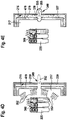
- Figure 6A is a diagram of an illustrative fibrous mat 530 with an intumescent material 335 before intumescence that is at least partially shaped in a corrugated way. As shown in Figure 6A , the arrangement of the fibrous mat 530 may be different than the arrangement of the fibrous mat 530 of Figure 5A .
- the fibrous mat 530 may be arranged between a battery casing 210 and a structural support layer 470 in accordance with some embodiments.
- the fibrous mat 530 is superficially cut along the ridges of the parallel folding lines 536.
- the superficial cuts along the ridges of the parallel folding lines 536 may ease folding of the fibrous mat 530 and/or reduce a spring effect.
- the functional layer 330 may include stabilizing means 610.
- the stabilizing means 610 may keep the fibrous mat 530 evenly distributed in the predetermined arrangement between the structural support layer 470 and the casing wall 215 in case of the exposure to a temperature that is below a predetermined temperature threshold (i.e., before intumescence of the intumescent material 335).
- the stabilizing means 610 may include at least one of pins, rods, or wires. If desired, the fibrous mat 530 is threaded onto the at least one of pins, rods, or wires.
- the functional layer 330 may include an additional intumescent material 637.
- the additional intumescent material 637 may form a coating 639 on the casing wall 215.
- the additional intumescent material 637 may form a coating 639 on the side of the structural support layer 470 that is oriented towards the casing wall instead.
- the additional intumescent material 637 may form a coating 639 on the casing wall 215 and on the side of the structural support layer 470 that is oriented towards the casing wall 215.
- Figure 6B is a diagram of the illustrative fibrous mat of Figure 6A with a hole 340 in the casing wall and in the fibrous mat, seen from the outside of the battery through a hole in the battery casing 210 in accordance with some embodiments.
- the hole in the battery casing 210 may be caused by an impact of a projectile on the battery casing 210.
- the temperature inside the battery may rise above a predetermined temperature threshold at which the intumescent material 335 intumesces.
- the functional layer 330 may increase in volume by at least a factor of 2, preferably by at least a factor of 3.
- Figure 6C is a diagram of the illustrative fibrous mat 530 of Figure 6A after intumescence of the intumescent material 335. As shown in Figure 6C , the stabilization means 610 allow free movement of the fibrous mat 530 upon intumescence of the intumescent material 335.
- Figure 6D shows the fibrous mat with the intumescent materials 337 and the additional intumescent material 637 after intumescence (i.e., in the form of expanded char) from the side of the battery casing 210
- Figure 6E is a diagram of the illustrative fibrous mat with the intumescent material 337 after intumescence seen from the side of the structural support layer 470 in accordance with some embodiments.
- intumescent materials 335, 637 after intumescence completely close the hole in the fibrous mat 530.
- intumescent materials 335 and/or 637 may ensure flame containment within the interior volume.
- intumescent materials 335, 637 may mitigate uncontrolled heat release from the interior volume through the breach of the battery casing 210.
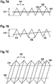
- FIG 7A is a diagram of an illustrative fibrous mat 530 with straight stabilizing means 610.
- the stabilizing means 610 may keep the fibrous mat evenly distributed in a predetermined arrangement between a structural support layer and a battery casing (e.g., structural support layer 470 and battery casing 210 of Figure 6A ).
- the fibrous mat 530 is shaped in a corrugated way with a predetermined height 532 and a predetermined distance 534 between parallel folding lines 536.
- the ratio between the predetermined height 532 and the predetermined distance 534 may be between 0.2 and 10.
- the ratio between the predetermined height 532 and the predetermined distance 534 is between 0.5 and 5.
- the fibrous mat 530 may be threaded onto the stabilizing means 610. If desired, the fibrous mat 530 may be threaded onto the stabilizing means 610 in a predetermined way. For example, the stabilizing means 610 may traverse each wrinkle of the fibrous mat 530 at the same height as shown in Figure 7A .
- Figure 7B is another diagram of an illustrative fibrous mat 530 with straight stabilizing means 610 for keeping the fibrous mat 530 evenly distributed in a predetermined arrangement between a structural support layer and a battery casing (e.g., structural support layer 470 and battery casing 210 of Figure 6A ). As shown in Figure 7B , the stabilizing means 610 may traverse each wrinkle of the fibrous mat 530 at a different height.
- Figure 7C is a three-dimensional diagram of an illustrative fibrous mat 530 with two parallel straight stabilizing means 610 for keeping the fibrous mat 530 evenly distributed in a predetermined arrangement between a structural support layer and a battery casing (e.g., structural support layer 470 and battery casing 210 of Figure 6A ).
- a structural support layer and a battery casing e.g., structural support layer 470 and battery casing 210 of Figure 6A .
- the two parallel straight stabilizing means 610 may both traverse each wrinkle of the fibrous mat 530 at the same height. If desired, the two parallel straight stabilizing means 610 may both traverse each wrinkle of the fibrous mat 530 at a different height. Illustratively, a first stabilizing means 610 of the at least two stabilizing means may traverse each wrinkle of the fibrous mat 530 at the same height, while a second stabilizing means 610 of the at least two stabilizing means traverses each wrinkle of the fibrous mat 530 at a different height.
- Figure 7D is a diagram of an illustrative fibrous mat 530 with rounded stabilizing means 610 for keeping the fibrous mat 530 evenly distributed in a predetermined arrangement between a structural support layer 470 and a battery casing 210.
- the stabilizing means 610 may traverse at least two wrinkles of the fibrous mat 530 at the same height and at least one other wrinkle of the fibrous mat 530 at a different height.
- the illustrative approaches of geometrically constraining the fibrous mat 530 before intumescence of the intumescent material shown in Figures 7A to 7D may enable the free movement of the fibrous mat 530 in lateral direction upon intumescence of the intumescent material.
- the fibrous mat 530 changes its properties and thus also the interaction with the former stabilizing means 610 onto which the fibrous mat 530 was threaded. Due to the softening, expansion, and foaming of the intumescent material during the thermally induced activation reaction, the fibrous mat 530 becomes free to move relative to the stabilizing means 610 in height and in lateral direction as permitted by the structural stabilizing means 470 and the battery casing 210.
- Figure 8 is a diagram of an illustrative fibrous mat 530 with and intumescent material (e.g., intumescent material 335 of Figure 5A or Figure 6A ) and stabilizing means 610 that form a functional layer between a battery casing and a structural support layer of a battery (e.g., between battery casing 210 and structural support layer 470 of a battery with battery cells 220 in an interior volume 217 as shown in Figures 4A to 4E ).
- intumescent material e.g., intumescent material 335 of Figure 5A or Figure 6A
- stabilizing means 610 that form a functional layer between a battery casing and a structural support layer of a battery (e.g., between battery casing 210 and structural support layer 470 of a battery with battery cells 220 in an interior volume 217 as shown in Figures 4A to 4E ).
- the stabilizing means 610 may keep the fibrous mat 530 evenly distributed in a predetermined arrangement between the structural support layer and the battery casing as long as the fibrous mat 530 is exposed to a temperature that is below a predetermined threshold temperature.
- the predetermined threshold temperature may be the temperature at which the intumescent material intumesces.
- the fibrous mat 530 may be at least partially shaped in a corrugated way with a predetermined distance 534 between parallel folding lines 536. If desired, the fibrous mat 530 may have a predetermined height between neighboring folding lines 536.
- the functional layer may include a resistive heating component 810 for activation of the intumescent material in the fibrous mat 530.
- the resistive heating component 810 may include metal wires, electrically conducting fibers (e.g., carbon fibers or metal coated fibers), or similar components that produce heat when traversed by an electrical current.
- the resistive heating component 810 may be electrically connected to a source of electrical energy that provides the electrical current to the resistive heating component 810.
- the source of electrical energy may be a power supply 820 such as a battery.
- the power supply 820 may include battery cells that are in an interior volume of the battery (e.g., battery cells 220 in interior volume 217 of Figures 4A to 4E ).
- a control switch 840 may couple the power supply 820 with the resistive heating component 810.
- the control switch 840 may be controlled by a control circuit 830.
- the control circuit 830 may include sensing and monitoring circuitry.
- the sensing and monitoring circuitry may include temperature sensing and monitoring circuitry (e.g., a temperature sensor) to detect overheating, caused for example by a thermal runaway of one or more battery cells in the interior volume of the battery (e.g., battery cells 220 in interior volume 217 of Figures 4A to 4E ).
- temperature sensing and monitoring circuitry e.g., a temperature sensor
- the sensing and monitoring circuitry may include voltage sensing and monitoring circuitry (e.g., a voltmeter) to detect damage, caused for example by an overcharging of one or more battery cells.
- voltage sensing and monitoring circuitry e.g., a voltmeter
- the sensing and monitoring circuitry may include current sensing and monitoring circuitry (e.g., an ammeter) to detect damage, caused for example by a short circuit in one or more battery cells.
- current sensing and monitoring circuitry e.g., an ammeter
- control circuit 830 may direct the control switch 840 to remain open for as long as the temperature sensing and monitoring circuitry detects a temperature that is below a predetermined temperature threshold, the voltage sensing and monitoring circuitry detects a voltage that is below a predetermined voltage threshold, and the current sensing and monitoring circuitry detects a current that is below a predetermined current threshold.
- control circuit 830 may direct closing of the control switch 840 as soon as the temperature sensing and monitoring circuitry detects a temperature that is equal to or above the predetermined temperature threshold, the voltage sensing and monitoring circuitry detects a voltage that is equal to or above the predetermined voltage threshold, or the current sensing and monitoring circuitry detects a current that is equal to or above the predetermined current threshold.
- an electrical current may pass through the resistive heating component 810.
- the electrical current may cause the resistive heating component 810 to generate heat in the fibrous mat 530.
- the generated heat may lead to the intumescence of the intumescent material.
- An actively triggered intumescence of the intumescent material in the fibrous mat 530 caused by the resistive heating component 810 has several advantages over a passively triggered intumescence of the intumescent material in the fibrous mat 530, for example caused by a fire in the interior volume of the battery.
- all the intumescent material in the fibrous mat 530 may experience a quasi-instantaneous and simultaneous intumescence when the battery cells in the interior volume are damaged and/or experiencing a potentially hazardous situation.
- intumescence of the intumescent material may not only depend on the temperature in the interior volume, but may also be triggered in other hazardous situations (e.g., caused by an overcharge or a short-circuit in one or more battery cells).
- the expanded char that results from the intumescence of the intumescent material may seal off the battery casing and/or close a breach in the battery casing before the heat and gases that are generated, for example by a thermal runaway of the battery cells, reach a breach in the battery casing.
- the actively triggered intumescence of the intumescent material may require additional systems and/or functionalities.
- the additional systems and/or functionalities may include a damage detection device that is integrated in the battery.
- the damage detection device may include the aforementioned temperature, voltage, and/or current sensing and monitoring circuitry.
- the damage detection device may trigger the control circuit 830 such that the control circuit 830 directs a closing of the control switch 840, which may activate the intumescence of the intumescent material by electrical resistive heating.
- the fibrous mat 530 of Figure 7A to Figure 7D is shown with one or two stabilizing means 610.
- any number of stabilizing means 610 may be used to keep the fibrous mat 530 in place before intumescence of the intumescent material, if desired.
- the intumescent material 637 of Figure 6A is shown to form a coating 639 on the side of the structural support layer 470 that is oriented towards the casing wall 215 or on the inside of the casing wall 215.
- the intumescent material 637 may form a coating instead or in addition on the side of the structural support layer 470 that is oriented towards the interior volume of the battery.
- the fibrous mat 530 of Figure 5A and 6A is shown to be at least partially shaped in a corrugated way between the casing wall 215 and the structural support layer 470.
- the fibrous mat 530 may be arranged between the casing wall 215 and the structural support layer 470 in a sinusoidal way, if desired.
- the battery 200 of Figure 2 and Figures 3A and 3B has a single gas evacuation venting tube 240. If desired, the battery 200 may have more than one gas evacuation venting tube 240. For example, the battery 200 may have two, three, four, five, six, seven or eight gas evacuation venting tubes.
- the fibrous mat 530 of Figures 5A to 8 is shown to be shaped in a corrugated way with a predetermined height and a predetermined distance between parallel folding lines. If desired, the predetermined distance between parallel folding lines and the predetermined height may be uniform throughout the entire fibrous mat 530 as illustrated in Figures 7A to 8 . However, the predetermined distance between parallel folding lines and/or the predetermined height may vary from wrinkle to wrinkle of the fibrous mat 530 as shown for some wrinkles of the fibrous mat 530 of Figure 5A .
Landscapes
- Chemical & Material Sciences (AREA)
- Chemical Kinetics & Catalysis (AREA)
- Electrochemistry (AREA)
- General Chemical & Material Sciences (AREA)
- Engineering & Computer Science (AREA)
- Aviation & Aerospace Engineering (AREA)
- Materials Engineering (AREA)
- Manufacturing & Machinery (AREA)
- Composite Materials (AREA)
- Inorganic Chemistry (AREA)
- Battery Mounting, Suspending (AREA)
Abstract
Description
- The present embodiments relate to a battery for an aircraft, and, more particularly, to a battery for an aircraft that is adapted to limit the consequences of a breach of the battery's casing. The present embodiments further relate to an aircraft with at least one battery that is adapted to limit the consequences of a breach of the battery's casing.
- Rechargeable and non-rechargeable lithium type batteries (i.e., lithium batteries and lithium-ion batteries) are currently used to some limited extent in aerospace applications. However, lithium type batteries are considered as the main technology for future electrification of aircrafts, in particular for high-energy and/or high-power applications.
- The chemistry and technology that is used in rechargeable and non-rechargeable lithium type batteries have inherent risks. For instance, lithium type batteries use electrolytes, that are known to be flammable. In case of an internal or external failure, a self-sustaining increase in temperature and pressure, which is sometimes also referred to as a thermal runaway, may occur.
- As a result, the battery casing, usually made of stainless steel, can be breached and toxic, hot, flammable, and/or corrosive fluids or gases including the flammable electrolyte and/or other material components of the lithium type battery may be released. Moreover, high temperatures and/or fire may be released from the battery casing. This is particularly hazardous when lithium type batteries are used in vehicles as surrounding vehicle structures or adjacent equipment may be damaged.
- Currently, the negative effects of an internal failure of a battery are managed by the battery casing and a gas evacuation provision that vents hot gases overboard in a controlled manner. The gas evacuation provision may prevent an increase in pressure inside the battery casing, thereby preventing an explosion of the battery.
- However, in some applications (e.g., in spacecraft or in military vehicles such as cars, trucks, tanks, aircraft, vessels, etc.) it may also be necessary to consider external impacts such as e.g. debris or ballistic impacts. These external impacts may breach the battery casing, damage the battery cells, and trigger internal battery failure. In such cases, an uncontained thermal runaway of the battery cells often occurs. Hot and/or flammable gases, heat and/or fire can neither be contained by the battery casing, nor can they be directed overboard in a controlled manner (e.g., through a gas evacuation venting tube).
- As a result, the hot and/or flammable gases as well as the heat and/or fire are often released in an uncontrolled manner and potentially threaten the integrity of the surrounding structures and/or that of adjacent equipment. Such a threat is considered unacceptable and needs to be mitigated.
- Some traditional mitigation techniques include the use of bullet-resistant and/or bulletproof armor protections around the battery that help to absorb and/or stop the penetration of external impacts caused by bullets or other ballistic threats. These bullet-resistant or bulletproof armor protections comprise many layers of woven or laminated fibers, or metal or ceramic plates. However, all these traditional mitigation techniques have the disadvantage of requiring a significant additional weight, which is unfavorable for some applications such as aerospace applications.
- Traditional techniques that deal with the problem of a ballistic impact include the use of materials with self-healing and/or sealing properties. For example, a polymeric functional material such as ionomer may close a hole created by a ballistic impact.
- Document
WO 2012/166494 A1 describes a system with one or more self-sealing panels and a cap member. The one or more self-sealing panels substantially cover an exterior surface of a liquid container. The cap member covers at least one of the following: one or more portions of the exterior surface of the liquid container; and an exterior surface of at least one of the one or more self-sealing panels. - Similar solutions are described in GORDON et al. Puncture Self-healing Polymers for Aerospace Applications. In: 242nd American Chemical Society National Meeting and Exposition, 28 August 2011, Denver, CO United States; KALISTA, Jr et al. Effect of Ionic Content on Ballistic Self-Healing in EMAA Copolymers and lonomers. In: Polymer Chemistry. Issue 18, 21 September 2013, pages 4823 to 5018; and VARLEY, R.J. and VAN DER ZWAAG, S. Towards an Understanding of Thermally Activated Self-Healing of an Ionomer System During Ballistic Penetration. In: Acta Materialia, Vol. 56, Issue 19, November 2008, pages 5737 to 5750.
- However, the presented solutions based on the use of self-healing polymers have the disadvantage that the polymer, used for the self-sealing property, will degrade at temperatures occurring during a thermal runaway of a battery. As a result, the polymer will lose its functionality at high temperatures that typically occur during a thermal runaway of a battery.
- In some systems directly related to batteries, the self-sealing material may be combined with multiple filler materials that assist the polymer to keep its functionality.
- For example, the document
US 2011/064997 A1 describes an impact resistant battery. The battery comprises a housing that includes a self-sealing ionomer material and that is filled with a material that suppresses flames and/or prevents the internal temperature from reaching an ignition point. - Similar solutions are described in document
WO 1997/045884 A2 and documentUS 9,136,558 B2 - However, in those solutions, the self-sealing property is still provided by the self-sealing ionomer alone. The fillers only act as flame retardant and/or to prevent the internal temperature from reaching an ignition point or as a mechanical stabilization.
- Some of these solutions include the use of intumescent materials. Intumescent materials are typically used in construction as passive fire protection of structural steel as well as firestop to avoid fire propagation. The use of intumescent material with lithium batteries is also already known. For example, in electric cars, a layer of intumescent material may be used between the casing and the battery for mitigating the propagation of heat to others battery compartments and/or to the car structure.
- Document
WO 2015/113133 A1 describes a battery housing comprising a body and a lid, providing a chamber dimensioned to hold at least one battery, and a venting passageway from the chamber. A portion of the body and the housing comprises an intumescent material with an expansion ratio sufficient to drive gas from the chamber through the venting passageway and to seal the chamber, when the material intumesces in the event of thermal runaway of a battery housed in the chamber. The body and the lid, provide a plurality of battery chambers, each dimensioned to hold at least one battery, and a plurality of venting passageways, each venting passageway extending from one battery chamber of the plurality of battery chambers. A portion of the body and the lid comprises an intumescent flame-retardant material with an expansion ratio sufficient to drive gas from any given battery chamber of the plurality of battery chambers through at least one of the plurality of venting passageways, and seal the given battery chamber, when the material intumesces in the event of thermal runaway of a battery housed in the given battery chamber. - Similar solutions are described in document
US 8,263,254 B2 , documentUS 2011/0300431 A1 , documentUS 2016/0336627 A1 , and documentUS 8,361,642 B2 . - However, these solutions are characterized by an intumescent material that is located around each battery cell of the battery in order to inactivate individual failed cells. Moreover, these documents only describe responses to an internal thermal runaway and does not describe solutions to mitigate a breach of the battery casing.
- It is, therefore, an objective to provide a new battery with a battery casing, whereby the new battery is adapted to mitigate the consequences of a breach of the battery casing. Furthermore, it is an objective to provide an aircraft having a new battery with a battery casing that is adapted to mitigate the consequences of a breach of the battery casing. This objective is solved by a battery comprising the features of claim 1.
- More specifically, a battery for an aircraft may comprise a battery casing with a casing wall that forms an interior volume; a plurality of battery cells that is arranged in the interior volume; and a functional layer that is arranged at the casing wall between the plurality of battery cells and the battery casing, wherein the functional layer comprises an intumescent material that, in case of a breach of the battery casing, is adapted to ensuring flame containment within the interior volume and mitigation of uncontrolled heat and gas emission from the interior volume through the breach of the battery casing.
- The functional layer may be provided in lithium-type batteries used in aircrafts such as airplanes, helicopters, or drones. The functional layer may not protect from a ballistic effect. In fact, a bullet may still penetrate the battery casing and damage the battery cells inside the battery casing.
- However, the functional layer may restore the containment capabilities of the breached battery casing by creating a fireproof and thermally insulating barrier between the battery cells and the battery casing. Furthermore, the fireproof and thermally insulating barrier may close the bullet hole and prevent gases from leaking out of the battery casing in an uncontrolled manner. Thus, the functional layer adds fail-safe characteristics to the battery in a way that hazardous gases and fire are still contained inside the battery casing even though the actual battery casing is damaged.
- In other words, the functional layer may close the bullet hole and force hot exhaust gases through a designed gas evacuation venting tube in a controlled manner during a thermal runaway of the damaged battery cells. Thereby, potential hazards of lithium-type batteries after a ballistic impact, including the uncontrolled release of flammable, toxic, corrosive gases and heat, etc. with effects on surrounding aircraft structures or adjacent equipment are mitigated.
- As opposed to traditional ballistic protection concepts, the functional layer of the presented battery has relatively low weight, which is particularly beneficial for the use of such batteries on aircrafts, such as airplanes, helicopters, or drones. In contrast, traditional ballistic protection means such as bullet-resistant or bulletproof armor may weigh between 40kg/m2 and 45kg/m2, whereby all faces of the batteries need to be protected.
- Furthermore, the installation of ballistic protection for the battery may be omitted. Thus, in addition to the ballistic protection, no integration devices such as fixation points, mountings, supporting frames, or brackets are required. Instead, the functional layer is integrated into the battery by the equipment manufacturer, resulting in reduced integration time, reduced weight, more available space, and reduced overall cost for the installation in the aircraft.
- Moreover, the present battery uses a single functional layer to achieve thermal protection, fire proofing, and the ability of sealing a damaged battery casing.
- According to another aspect, the above mentioned functionalities may be supported or further enhanced by a multilayer approach.
- According to one aspect, the plurality of battery cells comprises at least one of lithium-ion type, sodium-ion type, or magnesium-ion type battery cells.
- According to one aspect, the battery further comprises a gas evacuation venting tube that is adapted to enabling a controlled evacuation of gases in case of a thermal runaway of at least a portion of the plurality of battery cells.
- According to one aspect, the battery further comprises a structural support layer that encloses the plurality of battery cells and separates the plurality of battery cells from the functional layer.
- According to one aspect, the functional layer increases in volume upon intumescence of the intumescent material by at least a factor of 3.
- According to one aspect, the functional layer further comprises a fibrous mat that comprises the intumescent material, wherein the fibrous mat remains evenly distributed in a predetermined arrangement between the structural support layer and the casing wall in case of an exposure to a temperature that is below a predetermined threshold, and wherein the fibrous mat is free to move between the structural support layer and the casing wall in case of an exposure to a temperature that is equal to or above the predetermined threshold.
- According to one aspect, the fibrous mat comprises at least one of mineral wool, glass fibers, mineral fibers, alkaline earth silica fibers, carbon fibers, basalt fibers, binder, methylol melamine, phenol-formaldehyde resin, epoxy resin, pentaerythritol, monomer, dimer, trimer, starch, dextrin, sorbitol, mannitol, expandable graphite, exfoliating graphite, or char former polymer.
- According to one aspect, the fibrous mat is at least partially shaped in a corrugated way with a predetermined height and a predetermined distance between parallel folding lines.
- According to one aspect, the ratio between the predetermined height and the predetermined distance is between 0.5 and 5.
- According to one aspect, the fibrous mat is superficially cut along the ridges of the parallel folding lines.
- According to one aspect, the intumescent mat can be accumulated in one specific part of the battery housing.
- According to one aspect, the functional layer further comprises stabilizing means for keeping the fibrous mat evenly distributed in the predetermined arrangement between the structural support layer and the casing wall in case of the exposure to the temperature that is below the predetermined threshold.
- According to one aspect, the stabilizing means comprise at least one of pins, rods, or wires.
- According to one aspect, the fibrous mat is threaded onto the at least one of pins, rods, or wires.
- According to one aspect, the functional layer further comprises an additional intumescent material that forms a coating on the casing wall.
- According to one aspect, the intumescent material can be triggered electrically by a resistive heating device.
- According to one aspect, an additional intumescent coating can be applied on the (intumescent or not) fibrous mat to form the functional layer.
- According to one aspect, an additional polymer coating can be applied on the intumescent fibrous mat to form the functional layer.
- Moreover, an aircraft may comprise at least one battery as described above.
- Embodiments are outlined by way of example in the following description with reference to the attached drawings. In these attached drawings, identical or identically functioning components and elements are labeled with identical reference numbers and characters and are, consequently, only described once in the following description.
-
Figure 1 shows a perspective view of an illustrative aircraft with at least one battery in accordance with some embodiments, -
Figure 2 is a diagram of an illustrative battery with a battery casing and a plurality of battery cells in accordance with some embodiments, -
Figure 3A is a diagram of an illustrative battery with battery cells, a battery casing, a functional layer, and a gas evacuation venting tube in accordance with some embodiments, -
Figure 3B is a diagram of the illustrative battery ofFigure 3A after a breach of the battery casing that is followed by a thermal runaway of the battery cells and a mitigation of the breach in accordance with some embodiments, -
Figure 4A is a diagram of an illustrative battery with a functional layer with an intumescent material between a battery casing that forms an interior volume and a structural support layer before a bullet impact in accordance with some embodiments, -
Figure 4B is a diagram of the illustrative battery ofFigure 4A with the bullet hitting the battery casing in accordance with some embodiments, -
Figure 4C is a diagram of the illustrative battery ofFigure 4B in which the bullet damages a battery cell in accordance with some embodiments, -
Figure 4D is a diagram of the illustrative battery ofFigure 4C in which the damaged battery cell causes a fire with uncontrolled heat and gas emissions in accordance with some embodiments, -
Figure 4E is a diagram of the illustrative battery ofFigure 4D in which the functional layer increases in volume upon intumescence of the intumescent material, ensures flame containment within the interior volume, and mitigates uncontrolled heat release from the interior volume in accordance with some embodiments, -
Figure 5A is a diagram of an illustrative battery with a fibrous mat with an intumescent material before intumescence that is at least partially shaped in a corrugated way between a battery casing and a structural support layer in accordance with some embodiments, -
Figure 5B is a diagram of the illustrative battery ofFigure 5A seen from above in accordance with some embodiments, -
Figure 5C is a diagram of the battery ofFigure 5B with a bullet traversing the battery casing in accordance with some embodiments, -
Figure 5D is a diagram of the illustrative fibrous mat ofFigure 5C after traversal of the bullet and ensuing intumescence of the intumescent material seen from the side of the battery casing in accordance with some embodiments, -
Figure 5E is a diagram of the illustrative fibrous mat ofFigure 5C after traversal of the bullet and ensuing intumescence of the intumescent material seen from the side of the structural support layer in accordance with some embodiments, -
Figure 6A is a diagram of an illustrative fibrous mat with an intumescent material before intumescence that is at least partially shaped in a corrugated way between a battery casing and a structural support layer in accordance with some embodiments, -
Figure 6B is a diagram of the illustrative fibrous mat ofFigure 6A with a hole in the fibrous mat and in the battery casing, seen from outside the battery in accordance with some embodiments, -
Figure 6C is a diagram of the illustrative fibrous mat ofFigure 6A after intumescence of the intumescent material in accordance with some embodiments, -
Figure 6D is a diagram of the illustrative fibrous mat ofFigure 6B after intumescence of the intumescent material seen from the side of the battery casing in accordance with some embodiments, -
Figure 6E is a diagram of the illustrative fibrous mat ofFigure 6B after intumescence of the intumescent material seen from the side of the structural support layer in accordance with some embodiments, -
Figure 7A is a diagram of an illustrative fibrous mat with straight stabilizing means for keeping the fibrous mat evenly distributed in a predetermined arrangement between the structural support layer and the battery casing in accordance with some embodiments, -
Figure 7B is another diagram of an illustrative fibrous mat with straight stabilizing means for keeping the fibrous mat evenly distributed in a predetermined arrangement between the structural support layer and the battery casing in accordance with some embodiments, -
Figure 7C is a three-dimensional diagram of an illustrative fibrous mat with two parallel straight stabilizing means for keeping the fibrous mat evenly distributed in a predetermined arrangement between the structural support layer and the battery casing in accordance with some embodiments, -
Figure 7D is a diagram of an illustrative fibrous mat with rounded stabilizing means for keeping the fibrous mat evenly distributed in a predetermined arrangement between the structural support layer and the battery casing in accordance with some embodiments, and -
Figure 8 is a diagram of an illustrative fibrous mat with stabilizing means for keeping the fibrous mat evenly distributed in a predetermined arrangement between the structural support layer and the battery casing and a resistive heating component for activation of the intumescent material that is controlled by a control switch and a temperature sensor in accordance with some embodiments. - Embodiments may be included in transportation vehicles.
Figure 1 shows an example of a transportation vehicle. A transportation vehicle may be a spacecraft, an aircraft, a car, a bus, a truck, or a train, just to name a few. As shown inFigure 1 , the transportation vehicle may be anaircraft 100 that is exemplarily illustrated as a rotary-wing aircraft 100, and, more particularly, as a helicopter. - Thus, for purposes of simplicity and clarity, the
rotary wing aircraft 100 is hereinafter referred to as the "helicopter 100". The present invention is, however, not limited to helicopters and can likewise be applied to any other vehicle, in particular to vehicles with at least one battery. - By way of example, the
helicopter 100 comprises at least one multi-blademain rotor 101a for providing lift and forward or backward thrust during operation. The at least one multi-blademain rotor 101a preferentially comprises a plurality ofrotor blades rotor head 101d to a rotor shaft, which rotates in operation of thehelicopter 100 around an associated rotor axis. - The
helicopter 100 illustratively further comprises atail boom 103 and at least one preferentially shroudedcounter-torque device 104 configured to provide counter-torque during operation, i.e. to counter the torque created by rotation of the at least one multi-blademain rotor 101a for purposes of balancing thehelicopter 100 in terms of yaw. - The at least one
counter-torque device 104 is illustratively provided at an aft section of thetail boom 103 and preferably comprises atail rotor 104a. The aft section of thetail boom 103 preferably further comprises afin 105. -
Helicopter 100 may have anaircraft airframe 102. By way of example, thetail boom 103 may be connected to thefuselage 102 of thehelicopter 100. Theaircraft airframe 102 defines a supporting structure ofhelicopter 100 that is also referred to hereinafter as thefuselage 102 of thehelicopter 100. - Illustratively,
fuselage 102 forms an aircraftinterior region interior region cockpit 102a and may further accommodate acabin 102b. - Illustratively, the
cabin 102b may be adapted for the transportation of passengers and/or cargo, so that the rotary-wing aircraft 100 as a whole is adapted for the transportation of passengers. If desired, thecabin 102b may be adapted for accommodating operational and electrical equipment, such as e.g. a battery. - It should be noted that exemplary configurations of the
cabin 102b that are suitable for the transportation of passengers, but also for the accommodation of operational and electrical equipment, are readily available to the person skilled in the art and generally implemented to comply with applicable authority regulations and certification requirements regarding passenger transportation. Thus, these configurations of thecabin 102b are not described in detail for brevity and conciseness. - The
helicopter 100 may include an aircraftupper deck 106 and that illustratively forms an engineaccommodating region 107. Preferably, the aircraftupper deck 106 and, more particularly, at least theengine deck 106a is covered by acowling 108 that is mounted on top of thefuselage 102. - Illustratively, a battery may be installed in the engine
accommodating region 107. If desired, the battery may be a battery as described inFigure 2. Figure 2 is a diagram of anillustrative battery 200 with abattery casing 210 and a plurality ofbattery cells 220 in accordance with some embodiments. - The
battery casing 210 may comprise acasing wall 215 and form aninterior volume 217. Illustratively, the plurality ofbattery cells 220 is arranged in theinterior volume 217. If desired, the plurality ofbattery cells 220 may include at least one of lithium-ion type, sodium-ion type, or magnesium-ion type battery cells. - By way of example, the
battery 200 may include a gasevacuation venting tube 240. The gasevacuation venting tube 240 may be adapted to enabling a controlled evacuation of gases, for example in case of a thermal runaway of at least a portion of the plurality ofbattery cells 220. - If desired, the
battery 200 may include a functional layer. The functional layer may be arranged at thecasing wall 215 between the plurality ofbattery cells 220 and thebattery casing 210. Illustratively, the functional layer may include an intumescent material. - In case of a breach of the battery casing 210 (e.g., as the result of a ballistic impact), the intumescent material may be adapted to ensuring flame containment within the
interior volume 217 and mitigation of uncontrolled heat andgas emission 352 from theinterior volume 217 through the breach of thebattery casing 220. For example, the intumescent material may intumesce into an expanded char that provides a thermal insulation between the plurality ofbattery cells 220 and thecasing wall 215 and closes the breach of thebattery casing 210. -
Figure 3A is a diagram of anillustrative battery 200 withbattery cells 220, abattery casing 210, afunctional layer 330, and a gasevacuation venting tube 240 in accordance with some embodiments. Illustratively, thefunctional layer 330 may be arranged at thecasing wall 215. For example, thefunctional layer 330 may cover the entire interior surface of thecasing wall 215. - By way of example, the
functional layer 330 may include anintumescent material 335. Theintumescent material 335 may swell up and form an expanded char in case of an exposure to a temperature that is above a predetermined temperature threshold. For example, any fire inside theinterior volume 217 may expose theintumescent material 335 to a temperature that is above the predetermined temperature threshold, thereby leading to the intumescence of theintumescent material 335. - For example, a damage event that breaches the
battery casing 210 and damages one or more battery cells of the plurality ofbattery cells 220 may cause a thermal runaway of the one or more damaged battery cells that leads to a fire. Due to the fire, theintumescent material 335 may be exposed to a temperature above the predetermined temperature threshold and lead to the intumescence of theintumescent material 335. -
Figure 3B is a diagram of theillustrative battery 200 ofFigure 3A after abreach 340 of thebattery casing 210 that is followed by a thermal runaway of thebattery cells 220 in accordance with some embodiments. - By way of example, any impact on the
battery casing 210 may result in abreach 340 of thebattery casing 210. As an example, thebattery casing 210 may not move and be hit by flying debris, a bullet, shrapnel, or any other moving object. As another example, thebattery casing 210 may move and hit other equipment, the floor, or any other non-moving object. As yet another example, thebattery casing 210 may move and be hit by another moving object. - Consider the scenario in which a
breach 340 of thebattery casing 210 damages several battery cells of the plurality ofbattery cells 220. Consider further that the damaged battery cells experience a thermal runaway 360 that leads to a fire inside theinterior volume 217 of thebattery 200. In this scenario, the temperature inside theinterior volume 217 may rise and lead to the intumescence of the intumescent material withinfunctional layer 330, and thereby to the forming of an expandedchar 337. - Illustratively, the
functional layer 330 may increase in volume upon intumescence of the intumescent material by at least a factor of 2. Preferably, thefunctional layer 330 may increase in volume upon intumescence of the intumescent material by at least a factor of 3. In some embodiments, thefunctional layer 330 may increase in volume upon intumescence of the intumescent material by more than a factor of 4, The expandedchar 337 from the intumescent material after intumescence may have a lower thermal conductivity than the intumescent material before intumescence. - The expanded
char 337 may form aplug 355 that closes thebreach 340. If desired, thefunctional layer 330 with the intumescent material after intumescence may form an airtight or gas flow or convection barrier at thebreach 340. For example, thefunctional layer 330 may prevent flames and/or flammable gases from leaking through thebreach 340. - Thus, the expanded char 337 (i.e., the intumescent material after intumescence) may be adapted to ensuring flame containment within the
interior volume 217 and mitigation of uncontrolled heat and gas emission from theinterior volume 217 through thebreach 340 of thebattery casing 210. If desired, heat andgases 350 may be released through the gasevacuation venting tube 240 that is adapted to enabling the controlled evacuation ofgases 350. - Illustratively, a structural support layer may be provided. The structural support layer may assist with the arrangement of the
functional layer 330 at thecasing wall 215. -
Figure 4A is a diagram of an illustrative battery with afunctional layer 330 in accordance with some embodiments. Thefunctional layer 330 may include anintumescent material 335 and be arranged between abattery casing 210 that forms aninterior volume 217 and astructural support layer 470. The illustrative battery is shown before being hit by abullet 420. - Illustratively, the
structural support layer 470 may enclose a battery cell. If desired, thestructural support layer 470 may enclose a plurality of battery cells. For example, thestructural support layer 470 may separate the plurality of battery cells from thefunctional layer 330. - The
functional layer 330 may include a fibrous mat that comprises theintumescent material 335. If desired, thefunctional layer 330 may include an additional intumescent material. The additional intumescent material may form a coating on thecasing wall 215. -
Figure 4B is a diagram of the illustrative battery ofFigure 4A with thebullet 420 hitting thebattery casing 210 in accordance with some embodiments. Upon impact on thebattery casing 210, thebullet 420 may damage thecasing wall 215, thefunctional layer 330, and thestructural support layer 470. - The velocity and the caliber of the
bullet 420 may enable thebullet 420 to puncture thecasing wall 215, thefunctional layer 330, and thestructural support layer 470, thereby forming a breach of thebattery casing 210. - After traversing the
casing wall 215, thefunctional layer 330, and thestructural support layer 470, thebullet 420 may hit one or more of the plurality of battery cells inside thebattery casing 210. -
Figure 4C is a diagram of the illustrative battery ofFigure 4B in which thebullet 420 reaches and damages abattery cell 220 in accordance with some embodiments. - The damaged
battery cell 220 may become unstable. For example, the damagedbattery cell 220 may experience a thermal runaway and/or leak and release flammable, toxic, and/or corrosive gases. In some scenarios, the damagedbattery cell 220 may damageother battery cells 220 that were not damaged by the bullet. -
Figure 4D is a diagram of the illustrative battery ofFigure 4C in which the damagedbattery cell 220 experiences a thermal runaway 360 that causes a fire with uncontrolled heat andgas emissions 352. The fire may lead to an increase in temperature of thefunctional layer 330. As a result, theintumescent material 335 may intumesce. -
Figure 4E is a diagram of the illustrative battery ofFigure 4D in which thefunctional layer 330 increases in volume upon intumescence of theintumescent material 335. The expandedchar 337 that results from the intumescence of theintumescent material 335 may fill the majority of space between thestructural support layer 470 and thecasing wall 215 of thebattery casing 210. - Illustratively, the expanded
char 337 may form aplug 355 that closes thebreach 340 created by the bullet. Thereby, the expandedchar 337 may ensure flame containment within theinterior volume 217. - Preferably, the expanded char 337 (i.e., the
intumescent material 335 after intumescence) may mitigate uncontrolled heat release from theinterior volume 217. Thereby, the expandedchar 337 may ensure the safety of the equipment that surrounds the battery. - The
intumescent material 335 may be coated onto thecasing wall 215 of thebattery casing 210. Instead or in addition, a fibrous mat may include intumescent material. -
Figure 5A is a diagram of a battery with afunctional layer 330 that includes an illustrativefibrous mat 530 with anintumescent material 335 before intumescence. Thefibrous mat 530 may remain evenly distributed in a predetermined arrangement between thestructural support layer 470 and thecasing wall 215 of thebattery casing 210 in case of an exposure to a temperature that is below a predetermined threshold. - For example, the
fibrous mat 530 may remain evenly distributed in the predetermined arrangement between thestructural support layer 470 and thecasing wall 215 in case of an exposure to a temperature that is below the temperature that leads to the intumescence of theintumescent material 335. - Illustratively, the
fibrous mat 530 may be free to move between thestructural support layer 470 and thecasing wall 215 in case of an exposure to a temperature that is equal to or above the predetermined threshold. For example, thefibrous mat 530 may be free to move between thestructural support layer 470 and thecasing wall 215 in case of an exposure to a temperature that is equal to or above the temperature that leads to the intumescence of theintumescent material 335. - Illustratively, the
fibrous mat 530 may include at least one of mineral wool, glass fibers, mineral fibers, alkaline earth silica fibers, carbon fibers, basalt fibers, binder, methylol melamine, phenol-formaldehyde resin, epoxy resin, pentaerythritol, monomer, dimer, trimer, starch, dextrin, sorbitol, mannitol, expandable graphite, exfoliating graphite, or char former polymer. - As shown in
Figure 5A , thefibrous mat 530 may be at least partially shaped in a corrugated way with apredetermined height 532 and apredetermined distance 534 between parallelfolding lines 536. - Illustratively, the wrinkles of the
fibrous mat 530 may be oriented parallel to the direction from which a damaging event is expected to approach thebattery casing 210. Thus, the wrinkles of thefibrous mat 530 may be parallel to the normal direction of the adjacent surface of thecasing wall 215 of thebattery casing 210. - If desired, the ratio between the
predetermined height 532 and thepredetermined distance 534 may be between 0.2 and 10. Preferably, the ratio between thepredetermined height 532 and thepredetermined distance 534 may be between 0.5 and 5. - As an example, the
predetermined height 532 may be 25mm and thepredetermined distance 534 12.5mm, resulting in a ratio of 2 between thepredetermined height 532 and thepredetermined distance 534. As another example, thepredetermined height 532 may be 25mm and thepredetermined distance 534 21.3mm, resulting in a ratio of approximately 1.17 between thepredetermined height 532 and thepredetermined distance 534. - Illustratively, the
fibrous mat 530 may be superficially cut along the ridges of the parallel folding lines 536. For example, thefibrous mat 530 may be superficially cut along the ridges of theparallel folding lines 536 to ease folding of thefibrous mat 530 and/or to reduce the spring effect of the foldedfibrous mat 530. -
Figure 5B is a diagram of the illustrative battery casing ofFigure 5A seen from above, andFigure 5C is a diagram of a bullet traversing both thefibrous mat 530 and thebattery casing 210 ofFigure 5A in accordance with some embodiments. - The bullet may hit and damage one or more battery cells, which may lead to a fire inside the
battery casing 210. As a result, the temperature inside thebattery casing 210 may exceed the predetermined temperature threshold, above which theintumescent material 335 in thefibrous mat 530 intumesces. - Illustratively, the
fibrous mat 530 may increase in volume between the structural support layer and thebattery casing 210. Theintumescent material 335 in thefibrous mat 530 may lead to the closure of the hole in thefibrous mat 530 caused by the bullet. Thereby, theintumescent material 335 in thefibrous mat 530 may ensure flame containment within thebattery casing 210 and/or mitigation of uncontrolled heat and gas emission from the battery casing. -
Figure 5D is a diagram of the illustrativefibrous mat 530 ofFigure 5C after traversal of the bullet and ensuing intumescence of theintumescent material 335 seen from the side of thebattery casing 210.Figure 5E is a diagram of the illustrativefibrous mat 530 ofFigure 5C after traversal of the bullet and ensuing intumescence of theintumescent material 335 seen from the side of thestructural support layer 470 in accordance with some embodiments. - As shown in
Figure 5D and Figure 5E , theintumescent material 335 completely closes the hole in thefibrous mat 530 created by the bullet. Thus,intumescent material 335 may ensure flame containment within the interior volume. In addition,intumescent material 335 may mitigate uncontrolled heat release from the interior volume through thebreach 340 of thebattery casing 210. -
Figure 6A is a diagram of an illustrativefibrous mat 530 with anintumescent material 335 before intumescence that is at least partially shaped in a corrugated way. As shown inFigure 6A , the arrangement of thefibrous mat 530 may be different than the arrangement of thefibrous mat 530 ofFigure 5A . Thefibrous mat 530 may be arranged between abattery casing 210 and astructural support layer 470 in accordance with some embodiments. - Illustratively, the
fibrous mat 530 is superficially cut along the ridges of the parallel folding lines 536. The superficial cuts along the ridges of theparallel folding lines 536 may ease folding of thefibrous mat 530 and/or reduce a spring effect. - If desired, the
functional layer 330 may include stabilizingmeans 610. The stabilizing means 610 may keep thefibrous mat 530 evenly distributed in the predetermined arrangement between thestructural support layer 470 and thecasing wall 215 in case of the exposure to a temperature that is below a predetermined temperature threshold (i.e., before intumescence of the intumescent material 335). - Illustratively, the stabilizing means 610 may include at least one of pins, rods, or wires. If desired, the
fibrous mat 530 is threaded onto the at least one of pins, rods, or wires. - By way of example, the
functional layer 330 may include an additionalintumescent material 637. The additionalintumescent material 637 may form acoating 639 on thecasing wall 215. If desired, the additionalintumescent material 637 may form acoating 639 on the side of thestructural support layer 470 that is oriented towards the casing wall instead. Illustratively, the additionalintumescent material 637 may form acoating 639 on thecasing wall 215 and on the side of thestructural support layer 470 that is oriented towards thecasing wall 215. -
Figure 6B is a diagram of the illustrative fibrous mat ofFigure 6A with ahole 340 in the casing wall and in the fibrous mat, seen from the outside of the battery through a hole in thebattery casing 210 in accordance with some embodiments. The hole in thebattery casing 210 may be caused by an impact of a projectile on thebattery casing 210. - Consider the scenario in which the projectile damages a battery cell in the battery that causes a thermal runaway of the battery cell. In this scenario, the temperature inside the battery may rise above a predetermined temperature threshold at which the
intumescent material 335 intumesces. As a result of the intumescence of theintumescent material 335, thefunctional layer 330 may increase in volume by at least a factor of 2, preferably by at least a factor of 3. -
Figure 6C is a diagram of the illustrativefibrous mat 530 ofFigure 6A after intumescence of theintumescent material 335. As shown inFigure 6C , the stabilization means 610 allow free movement of thefibrous mat 530 upon intumescence of theintumescent material 335. -
Figure 6D shows the fibrous mat with theintumescent materials 337 and the additionalintumescent material 637 after intumescence (i.e., in the form of expanded char) from the side of thebattery casing 210, andFigure 6E is a diagram of the illustrative fibrous mat with theintumescent material 337 after intumescence seen from the side of thestructural support layer 470 in accordance with some embodiments. - As shown in
Figure 6D and Figure 6E , theintumescent materials fibrous mat 530. Thus,intumescent materials 335 and/or 637 may ensure flame containment within the interior volume. In addition,intumescent materials battery casing 210. -
Figure 7A is a diagram of an illustrativefibrous mat 530 with straight stabilizingmeans 610. The stabilizing means 610 may keep the fibrous mat evenly distributed in a predetermined arrangement between a structural support layer and a battery casing (e.g.,structural support layer 470 andbattery casing 210 ofFigure 6A ). - As shown in
Figure 7A , thefibrous mat 530 is shaped in a corrugated way with apredetermined height 532 and apredetermined distance 534 between parallelfolding lines 536. The ratio between thepredetermined height 532 and thepredetermined distance 534 may be between 0.2 and 10. Preferably, the ratio between thepredetermined height 532 and thepredetermined distance 534 is between 0.5 and 5. - The
fibrous mat 530 may be threaded onto the stabilizingmeans 610. If desired, thefibrous mat 530 may be threaded onto the stabilizing means 610 in a predetermined way. For example, the stabilizing means 610 may traverse each wrinkle of thefibrous mat 530 at the same height as shown inFigure 7A . -
Figure 7B is another diagram of an illustrativefibrous mat 530 with straight stabilizingmeans 610 for keeping thefibrous mat 530 evenly distributed in a predetermined arrangement between a structural support layer and a battery casing (e.g.,structural support layer 470 andbattery casing 210 ofFigure 6A ). As shown inFigure 7B , the stabilizing means 610 may traverse each wrinkle of thefibrous mat 530 at a different height. -
Figure 7C is a three-dimensional diagram of an illustrativefibrous mat 530 with two parallelstraight stabilizing means 610 for keeping thefibrous mat 530 evenly distributed in a predetermined arrangement between a structural support layer and a battery casing (e.g.,structural support layer 470 andbattery casing 210 ofFigure 6A ). - The two parallel
straight stabilizing means 610 may both traverse each wrinkle of thefibrous mat 530 at the same height. If desired, the two parallelstraight stabilizing means 610 may both traverse each wrinkle of thefibrous mat 530 at a different height. Illustratively, a first stabilizing means 610 of the at least two stabilizing means may traverse each wrinkle of thefibrous mat 530 at the same height, while a second stabilizing means 610 of the at least two stabilizing means traverses each wrinkle of thefibrous mat 530 at a different height. -
Figure 7D is a diagram of an illustrativefibrous mat 530 with rounded stabilizingmeans 610 for keeping thefibrous mat 530 evenly distributed in a predetermined arrangement between astructural support layer 470 and abattery casing 210. In other words, the stabilizing means 610 may traverse at least two wrinkles of thefibrous mat 530 at the same height and at least one other wrinkle of thefibrous mat 530 at a different height. - The illustrative approaches of geometrically constraining the
fibrous mat 530 before intumescence of the intumescent material shown inFigures 7A to 7D may enable the free movement of thefibrous mat 530 in lateral direction upon intumescence of the intumescent material. - During intumescence, the
fibrous mat 530 changes its properties and thus also the interaction with the former stabilizing means 610 onto which thefibrous mat 530 was threaded. Due to the softening, expansion, and foaming of the intumescent material during the thermally induced activation reaction, thefibrous mat 530 becomes free to move relative to the stabilizing means 610 in height and in lateral direction as permitted by the structural stabilizing means 470 and thebattery casing 210. -
Figure 8 is a diagram of an illustrativefibrous mat 530 with and intumescent material (e.g.,intumescent material 335 ofFigure 5A orFigure 6A ) and stabilizingmeans 610 that form a functional layer between a battery casing and a structural support layer of a battery (e.g., betweenbattery casing 210 andstructural support layer 470 of a battery withbattery cells 220 in aninterior volume 217 as shown inFigures 4A to 4E ). - The stabilizing means 610 may keep the
fibrous mat 530 evenly distributed in a predetermined arrangement between the structural support layer and the battery casing as long as thefibrous mat 530 is exposed to a temperature that is below a predetermined threshold temperature. The predetermined threshold temperature may be the temperature at which the intumescent material intumesces. - By way of example, the
fibrous mat 530 may be at least partially shaped in a corrugated way with apredetermined distance 534 between parallelfolding lines 536. If desired, thefibrous mat 530 may have a predetermined height between neighboringfolding lines 536. - Illustratively, the functional layer may include a
resistive heating component 810 for activation of the intumescent material in thefibrous mat 530. Theresistive heating component 810 may include metal wires, electrically conducting fibers (e.g., carbon fibers or metal coated fibers), or similar components that produce heat when traversed by an electrical current. - By way of example, the
resistive heating component 810 may be electrically connected to a source of electrical energy that provides the electrical current to theresistive heating component 810. As shown inFigure 8 , the source of electrical energy may be a power supply 820 such as a battery. If desired, the power supply 820 may include battery cells that are in an interior volume of the battery (e.g.,battery cells 220 ininterior volume 217 ofFigures 4A to 4E ). - Illustratively, a
control switch 840 may couple the power supply 820 with theresistive heating component 810. Thecontrol switch 840 may be controlled by acontrol circuit 830. If desired, thecontrol circuit 830 may include sensing and monitoring circuitry. - As an example, the sensing and monitoring circuitry may include temperature sensing and monitoring circuitry (e.g., a temperature sensor) to detect overheating, caused for example by a thermal runaway of one or more battery cells in the interior volume of the battery (e.g.,
battery cells 220 ininterior volume 217 ofFigures 4A to 4E ). - As another example, the sensing and monitoring circuitry may include voltage sensing and monitoring circuitry (e.g., a voltmeter) to detect damage, caused for example by an overcharging of one or more battery cells.
- As yet another example, the sensing and monitoring circuitry may include current sensing and monitoring circuitry (e.g., an ammeter) to detect damage, caused for example by a short circuit in one or more battery cells.
- Illustratively, the
control circuit 830 may direct thecontrol switch 840 to remain open for as long as the temperature sensing and monitoring circuitry detects a temperature that is below a predetermined temperature threshold, the voltage sensing and monitoring circuitry detects a voltage that is below a predetermined voltage threshold, and the current sensing and monitoring circuitry detects a current that is below a predetermined current threshold. - Thus, no electrical current flows through the
resistive heating component 810 and no heat is produced by theresistive heating component 810 as long as the temperature sensing and monitoring circuitry detects a temperature below the predetermined temperature threshold, the voltage sensing and monitoring circuitry detects a voltage below the predetermined voltage threshold, and the current sensing and monitoring circuitry detects a current below the predetermined current threshold. - As another example, the
control circuit 830 may direct closing of thecontrol switch 840 as soon as the temperature sensing and monitoring circuitry detects a temperature that is equal to or above the predetermined temperature threshold, the voltage sensing and monitoring circuitry detects a voltage that is equal to or above the predetermined voltage threshold, or the current sensing and monitoring circuitry detects a current that is equal to or above the predetermined current threshold. - In response to closing the
control switch 840, an electrical current may pass through theresistive heating component 810. The electrical current may cause theresistive heating component 810 to generate heat in thefibrous mat 530. The generated heat may lead to the intumescence of the intumescent material. - An actively triggered intumescence of the intumescent material in the
fibrous mat 530 caused by theresistive heating component 810 has several advantages over a passively triggered intumescence of the intumescent material in thefibrous mat 530, for example caused by a fire in the interior volume of the battery. - For example, all the intumescent material in the
fibrous mat 530 may experience a quasi-instantaneous and simultaneous intumescence when the battery cells in the interior volume are damaged and/or experiencing a potentially hazardous situation. - Moreover, intumescence of the intumescent material may not only depend on the temperature in the interior volume, but may also be triggered in other hazardous situations (e.g., caused by an overcharge or a short-circuit in one or more battery cells).
- Furthermore, the expanded char that results from the intumescence of the intumescent material may seal off the battery casing and/or close a breach in the battery casing before the heat and gases that are generated, for example by a thermal runaway of the battery cells, reach a breach in the battery casing.
- However, the actively triggered intumescence of the intumescent material may require additional systems and/or functionalities. For example, the additional systems and/or functionalities may include a damage detection device that is integrated in the battery.
- If desired, the damage detection device may include the aforementioned temperature, voltage, and/or current sensing and monitoring circuitry. In case of a damage event, the damage detection device may trigger the
control circuit 830 such that thecontrol circuit 830 directs a closing of thecontrol switch 840, which may activate the intumescence of the intumescent material by electrical resistive heating. - It should be noted that modifications to the above described embodiments are within the common knowledge of the person skilled in the art and, thus, also considered as being part of the present invention.
- For example, the
fibrous mat 530 ofFigure 7A to Figure 7D is shown with one or two stabilizingmeans 610. However, any number of stabilizingmeans 610 may be used to keep thefibrous mat 530 in place before intumescence of the intumescent material, if desired. - Furthermore, the
intumescent material 637 ofFigure 6A is shown to form acoating 639 on the side of thestructural support layer 470 that is oriented towards thecasing wall 215 or on the inside of thecasing wall 215. However, theintumescent material 637 may form a coating instead or in addition on the side of thestructural support layer 470 that is oriented towards the interior volume of the battery. - Moreover, the
fibrous mat 530 ofFigure 5A and6A is shown to be at least partially shaped in a corrugated way between thecasing wall 215 and thestructural support layer 470. However, thefibrous mat 530 may be arranged between thecasing wall 215 and thestructural support layer 470 in a sinusoidal way, if desired. - Additionally, the
battery 200 ofFigure 2 andFigures 3A and 3B has a single gasevacuation venting tube 240. If desired, thebattery 200 may have more than one gasevacuation venting tube 240. For example, thebattery 200 may have two, three, four, five, six, seven or eight gas evacuation venting tubes. - Furthermore, the
fibrous mat 530 ofFigures 5A to 8 is shown to be shaped in a corrugated way with a predetermined height and a predetermined distance between parallel folding lines. If desired, the predetermined distance between parallel folding lines and the predetermined height may be uniform throughout the entirefibrous mat 530 as illustrated inFigures 7A to 8 . However, the predetermined distance between parallel folding lines and/or the predetermined height may vary from wrinkle to wrinkle of thefibrous mat 530 as shown for some wrinkles of thefibrous mat 530 ofFigure 5A . -
- 100
- aircraft
- 101a
- multi-blade main rotor
- 101b, 101c
- rotor blades
- 101d
- rotor head
- 102
- aircraft airframe, fuselage
- 102a
- cockpit
- 102b
- cabin
- 103
- tail boom
- 104
- counter-torque device
- 104a
- tail rotor
- 105
- fin
- 106
- aircraft upper deck
- 106a
- engine deck
- 107
- engine accommodating region
- 108
- cowling
- 200
- battery
- 210
- battery casing
- 215
- casing wall
- 217
- interior volume
- 220
- battery cells
- 240
- gas evacuation venting tube
- 330
- functional layer
- 335
- intumescent material
- 337
- expanded char
- 340
- breach
- 350
- controlled heat and gas release
- 352
- uncontrolled heat and gas emission
- 355
- plug
- 360
- thermal runaway
- 420
- ballistic threat, bullet
- 470
- structural support layer
- 530
- fibrous mat
- 532
- height
- 534
- distance
- 536
- parallel folding lines
- 610
- stabilizing means
- 637
- intumescent material
- 639
- coating
- 810
- resistive heating component
- 820
- power supply
- 830
- control circuit
- 840
- controlled switch
Claims (15)
- A battery (200) for an aircraft (100), comprising:a battery casing (210) with a casing wall (215) that forms an interior volume (217);a plurality of battery cells (220) that is arranged in the interior volume (217); anda functional layer (330) that is arranged at the casing wall (215) between the plurality of battery cells (220) and the battery casing (210), wherein the functional layer (330) comprises an intumescent material (335) that, in case of a breach (340) of the battery casing (210), is adapted to ensuring flame containment within the interior volume (217) and mitigation of uncontrolled heat and gas emission (352) from the interior volume (217) through the breach (340) of the battery casing (210).
- The battery (200) of claim 1, wherein the plurality of battery cells (220) comprises at least one of lithium-ion type, sodium-ion type, or magnesium-ion type battery cells.
- The battery (200) of any one of claims 1 or 2, further comprising:
a gas evacuation venting tube (240) that is adapted to enabling a controlled evacuation of gases (350) in case of a thermal runaway (360) of at least a portion of the plurality of battery cells (220). - The battery (200) of any one of the preceding claims, further comprising:
a structural support layer (470) that encloses the plurality of battery cells (220) and separates the plurality of battery cells (220) from the functional layer (330). - The battery (200) of claim 4, wherein the functional layer (330) increases in volume upon intumescence of the intumescent material (335) by at least a factor of 3.
- The battery (200) of claim 4, wherein the functional layer (330) further comprises:
a fibrous mat (530) that comprises the intumescent material (335), wherein the fibrous mat (530) remains evenly distributed in a predetermined arrangement between the structural support layer (470) and the casing wall (215) in case of an exposure to a temperature that is below a predetermined threshold, and wherein the fibrous mat (530) is free to move between the structural support layer (470) and the casing wall (215) in case of an exposure to a temperature that is equal to or above the predetermined threshold. - The battery (200) of claim 6, wherein the fibrous mat (530) comprises at least one of mineral wool, glass fibers, mineral fibers, alkaline earth silica fibers, carbon fibers, basalt fibers, binder, methylol melamine, phenol-formaldehyde resin, epoxy resin, pentaerythritol, monomer, dimer, trimer, starch, dextrin, sorbitol, mannitol, expandable graphite, exfoliating graphite, or char former polymer.
- The battery (200) of claim 6, wherein the fibrous mat (530) is at least partially shaped in a corrugated way with a predetermined height (532) and a predetermined distance (534) between parallel folding lines (536).
- The battery (200) of claim 8, wherein the ratio between the predetermined height (532) and the predetermined distance (534) is between 0.5 and 5.
- The battery (200) of claim 8, wherein the fibrous mat (530) is superficially cut along the ridges of the parallel folding lines (536).
- The battery (200) of claim 8, wherein the functional layer (330) further comprises:
stabilizing means (610) for keeping the fibrous mat (530) evenly distributed in the predetermined arrangement between the structural support layer (470) and the casing wall (215) in case of the exposure to the temperature that is below the predetermined threshold. - The battery (200) of claim 11, wherein the stabilizing means (610) comprise at least one of pins, rods, or wires.
- The battery (200) of claim 12, wherein the fibrous mat (530) is threaded onto the at least one of pins, rods, or wires.
- The battery (200) of any one of the preceding claims, wherein the functional layer (330) further comprises:
an additional intumescent material (637) that forms a coating (639) on the casing wall (215). - An aircraft (100) with a battery (200) of any one of the preceding claims.
Priority Applications (3)
| Application Number | Priority Date | Filing Date | Title |
|---|---|---|---|
| EP20400018.6A EP3985784A1 (en) | 2020-10-15 | 2020-10-15 | A battery for an aircraft |
| KR1020210069005A KR102613406B1 (en) | 2020-10-15 | 2021-05-28 | A battery for an aircraft |
| US17/350,674 US11658363B2 (en) | 2020-10-15 | 2021-06-17 | Battery for an aircraft |
Applications Claiming Priority (1)
| Application Number | Priority Date | Filing Date | Title |
|---|---|---|---|
| EP20400018.6A EP3985784A1 (en) | 2020-10-15 | 2020-10-15 | A battery for an aircraft |
Publications (1)
| Publication Number | Publication Date |
|---|---|
| EP3985784A1 true EP3985784A1 (en) | 2022-04-20 |
Family
ID=74141326
Family Applications (1)
| Application Number | Title | Priority Date | Filing Date |
|---|---|---|---|
| EP20400018.6A Pending EP3985784A1 (en) | 2020-10-15 | 2020-10-15 | A battery for an aircraft |
Country Status (3)
| Country | Link |
|---|---|
| US (1) | US11658363B2 (en) |
| EP (1) | EP3985784A1 (en) |
| KR (1) | KR102613406B1 (en) |
Cited By (2)
| Publication number | Priority date | Publication date | Assignee | Title |
|---|---|---|---|---|
| US20230369682A1 (en) * | 2022-05-16 | 2023-11-16 | GM Global Technology Operations LLC | Battery pack system with thermal runaway mitigation features |
| WO2023247584A1 (en) | 2022-06-24 | 2023-12-28 | Zephyros, Inc. | Thermal runaway fumes management |
Families Citing this family (6)
| Publication number | Priority date | Publication date | Assignee | Title |
|---|---|---|---|---|
| US12051814B2 (en) * | 2021-08-06 | 2024-07-30 | GM Global Technology Operations LLC | Flame-retardant compositions for energy storage devices, methods of manufacture thereof and batteries containing the same |
| US11984611B2 (en) * | 2021-08-17 | 2024-05-14 | Beta Air, Llc | Stack battery pack for electric vertical take-off and landing aircraft |
| EP4603392A3 (en) * | 2022-07-19 | 2025-09-24 | AIRBUS HELICOPTERS DEUTSCHLAND GmbH | A rotorcraft with an energy source storage unit |
| US20250062490A1 (en) * | 2023-08-18 | 2025-02-20 | Fca Us Llc | High voltage battery deployable exhaust system |
| KR20250131116A (en) * | 2024-02-26 | 2025-09-02 | 주식회사 엘지에너지솔루션 | Battery module and battery pack including the same and vehicle including the same |
| EP4621949A1 (en) | 2024-03-20 | 2025-09-24 | Airbus S.A.S. | Quenching arrangment, energy storage device and vehicle comprising same |
Citations (10)
| Publication number | Priority date | Publication date | Assignee | Title |
|---|---|---|---|---|
| WO1997045884A2 (en) | 1996-05-28 | 1997-12-04 | Gitto/Global Corporation | Flame-retardant battery casing |
| US20110064997A1 (en) | 2009-08-14 | 2011-03-17 | Justin Peskar | Impact resistant battery |
| US20110300431A1 (en) | 2010-06-07 | 2011-12-08 | Bluefin Robotics Corporation | Method of protecting battery cells and batteries which contain battery cells and protected battery cells and batteries which contain battery cells |
| US8263254B2 (en) | 2009-07-17 | 2012-09-11 | Tesla Motors, Inc. | Cell with an outer layer of intumescent material |
| US20120308859A1 (en) * | 2009-04-22 | 2012-12-06 | Tesla Motors, Inc. | Battery Pack Enclosure with Controlled Thermal Runaway Release System |
| WO2012166494A1 (en) | 2011-05-27 | 2012-12-06 | Hutchinson S.A. | Self-sealing liquid containment system and method of installing same |
| WO2015113133A1 (en) | 2014-02-03 | 2015-08-06 | Pyrophobic Systems Ltd. | Intumescent battery housing |
| US20160336627A1 (en) | 2015-05-12 | 2016-11-17 | GM Global Technology Operations LLC | Thermal propagation mitigation for hv battery modules |
| EP3460870A1 (en) * | 2017-09-25 | 2019-03-27 | Ursatech Ltd. | Thermal runaway retarding battery housing |
| US20190207188A1 (en) * | 2018-01-03 | 2019-07-04 | Unifrax I Llc | Electrical and thermal protection coating and electrochemical battery including same |
Family Cites Families (5)
| Publication number | Priority date | Publication date | Assignee | Title |
|---|---|---|---|---|
| JP4434237B2 (en) * | 2007-06-20 | 2010-03-17 | トヨタ自動車株式会社 | Power storage device for vehicle and vehicle |
| US7736799B1 (en) * | 2009-07-17 | 2010-06-15 | Tesla Motors, Inc. | Method and apparatus for maintaining cell wall integrity during thermal runaway using an outer layer of intumescent material |
| CN104284700A (en) * | 2012-04-24 | 2015-01-14 | 维美德汽车公司 | Battery pack with fire preventing agent |
| JP2018098074A (en) * | 2016-12-14 | 2018-06-21 | 三菱自動車工業株式会社 | Battery pack |
| US10490785B1 (en) * | 2018-07-20 | 2019-11-26 | Firefree Coatings, Inc. | Containment, storage and shipping of lithium batteries |
-
2020
- 2020-10-15 EP EP20400018.6A patent/EP3985784A1/en active Pending
-
2021
- 2021-05-28 KR KR1020210069005A patent/KR102613406B1/en active Active
- 2021-06-17 US US17/350,674 patent/US11658363B2/en active Active
Patent Citations (12)
| Publication number | Priority date | Publication date | Assignee | Title |
|---|---|---|---|---|
| WO1997045884A2 (en) | 1996-05-28 | 1997-12-04 | Gitto/Global Corporation | Flame-retardant battery casing |
| US20120308859A1 (en) * | 2009-04-22 | 2012-12-06 | Tesla Motors, Inc. | Battery Pack Enclosure with Controlled Thermal Runaway Release System |
| US8361642B2 (en) | 2009-04-22 | 2013-01-29 | Tesla Motors, Inc. | Battery pack enclosure with controlled thermal runaway release system |
| US8263254B2 (en) | 2009-07-17 | 2012-09-11 | Tesla Motors, Inc. | Cell with an outer layer of intumescent material |
| US20110064997A1 (en) | 2009-08-14 | 2011-03-17 | Justin Peskar | Impact resistant battery |
| US9136558B2 (en) | 2009-08-14 | 2015-09-15 | Philips Plastics Corporation | Impact resistant battery |
| US20110300431A1 (en) | 2010-06-07 | 2011-12-08 | Bluefin Robotics Corporation | Method of protecting battery cells and batteries which contain battery cells and protected battery cells and batteries which contain battery cells |
| WO2012166494A1 (en) | 2011-05-27 | 2012-12-06 | Hutchinson S.A. | Self-sealing liquid containment system and method of installing same |
| WO2015113133A1 (en) | 2014-02-03 | 2015-08-06 | Pyrophobic Systems Ltd. | Intumescent battery housing |
| US20160336627A1 (en) | 2015-05-12 | 2016-11-17 | GM Global Technology Operations LLC | Thermal propagation mitigation for hv battery modules |
| EP3460870A1 (en) * | 2017-09-25 | 2019-03-27 | Ursatech Ltd. | Thermal runaway retarding battery housing |
| US20190207188A1 (en) * | 2018-01-03 | 2019-07-04 | Unifrax I Llc | Electrical and thermal protection coating and electrochemical battery including same |
Non-Patent Citations (3)
| Title |
|---|
| GORDON ET AL.: "242nd American Chemical Society National Meeting and Exposition", 28 August 2011, DENVER, CO, article "Puncture Self-healing Polymers for Aerospace Applications" |
| KALISTA, JR ET AL.: "Effect of Ionic Content on Ballistic Self-Healing in EMAA Copolymers and lonomers", POLYMER CHEMISTRY, 21 September 2013 (2013-09-21), pages 4823 - 5018 |
| VARLEY, R.J.VAN DER ZWAAG, S.: "Towards an Understanding of Thermally Activated Self-Healing of an Ionomer System During Ballistic Penetration", ACTA MATERIALIA, vol. 56, November 2008 (2008-11-01), pages 5737 - 5750, XP055330521, DOI: 10.1016/j.actamat.2008.08.008 |
Cited By (3)
| Publication number | Priority date | Publication date | Assignee | Title |
|---|---|---|---|---|
| US20230369682A1 (en) * | 2022-05-16 | 2023-11-16 | GM Global Technology Operations LLC | Battery pack system with thermal runaway mitigation features |
| US12308412B2 (en) * | 2022-05-16 | 2025-05-20 | GM Global Technology Operations LLC | Battery pack system with thermal runaway mitigation features |
| WO2023247584A1 (en) | 2022-06-24 | 2023-12-28 | Zephyros, Inc. | Thermal runaway fumes management |
Also Published As
| Publication number | Publication date |
|---|---|
| KR102613406B1 (en) | 2023-12-12 |
| KR20220050022A (en) | 2022-04-22 |
| US20220123409A1 (en) | 2022-04-21 |
| US11658363B2 (en) | 2023-05-23 |
Similar Documents
| Publication | Publication Date | Title |
|---|---|---|
| US11658363B2 (en) | Battery for an aircraft | |
| US12294073B2 (en) | Heat shield | |
| US11837743B2 (en) | Battery with a fire protection device and motor vehicle | |
| JP2023175722A (en) | Device for mitigation of thermal event propagation in battery systems | |
| US5762145A (en) | Highway vehicle fuel tank fire protection device | |
| JP2024122986A (en) | Thermal Barrier Materials for Rechargeable Electrical Energy Storage Systems | |
| EP2959522B1 (en) | Enclosure for rechargeable batteries | |
| US9868545B2 (en) | Primary structure for an attachment pylon with firewall and thermal layers | |
| US20230187771A1 (en) | Battery arrangement and method for discharging a gas from a battery cell | |
| KR101128318B1 (en) | Methods and apparatus for controlling hazardous and/or flammable materials | |
| US8439123B2 (en) | Methods and apparatus for controlling hazards | |
| US20110042515A1 (en) | Arrangement for providing active fire protection in aircraft | |
| EP4265526A1 (en) | Fire, explosion and liquefaction protection system | |
| EP2874810A1 (en) | Fire guards and materials therefor | |
| WO2019089950A1 (en) | Safety lithium-ion battery system | |
| CN112074970A (en) | Vehicle with high-pressure accumulator | |
| GB2519067A (en) | Fire guards and materials therefor | |
| US9786883B2 (en) | Battery containment mesh | |
| CN115700942A (en) | Battery equipment and motor vehicles with fire protection | |
| US20160271431A1 (en) | Safety device for aircraft | |
| US12537264B2 (en) | Battery module enclosure with stiffening structure | |
| GB2625255A (en) | Electric vehicle battery pack | |
| US20250141004A1 (en) | Battery pack module | |
| WO2024009105A2 (en) | Enclosure | |
| US20250140945A1 (en) | Battery pack module |
Legal Events
| Date | Code | Title | Description |
|---|---|---|---|
| PUAI | Public reference made under article 153(3) epc to a published international application that has entered the european phase |
Free format text: ORIGINAL CODE: 0009012 |
|
| STAA | Information on the status of an ep patent application or granted ep patent |
Free format text: STATUS: THE APPLICATION HAS BEEN PUBLISHED |
|
| STAA | Information on the status of an ep patent application or granted ep patent |
Free format text: STATUS: REQUEST FOR EXAMINATION WAS MADE |
|
| AK | Designated contracting states |
Kind code of ref document: A1 Designated state(s): AL AT BE BG CH CY CZ DE DK EE ES FI FR GB GR HR HU IE IS IT LI LT LU LV MC MK MT NL NO PL PT RO RS SE SI SK SM TR |
|
| 17P | Request for examination filed |
Effective date: 20220323 |
|
| RBV | Designated contracting states (corrected) |
Designated state(s): AL AT BE BG CH CY CZ DE DK EE ES FI FR GB GR HR HU IE IS IT LI LT LU LV MC MK MT NL NO PL PT RO RS SE SI SK SM TR |
|
| P01 | Opt-out of the competence of the unified patent court (upc) registered |
Effective date: 20230530 |