EP3985436A1 - Projection screen - Google Patents
Projection screen Download PDFInfo
- Publication number
- EP3985436A1 EP3985436A1 EP20837041.1A EP20837041A EP3985436A1 EP 3985436 A1 EP3985436 A1 EP 3985436A1 EP 20837041 A EP20837041 A EP 20837041A EP 3985436 A1 EP3985436 A1 EP 3985436A1
- Authority
- EP
- European Patent Office
- Prior art keywords
- triangular pyramid
- projection screen
- units
- layer
- pyramid units
- Prior art date
- Legal status (The legal status is an assumption and is not a legal conclusion. Google has not performed a legal analysis and makes no representation as to the accuracy of the status listed.)
- Granted
Links
Images



Classifications
-
- G—PHYSICS
- G03—PHOTOGRAPHY; CINEMATOGRAPHY; ANALOGOUS TECHNIQUES USING WAVES OTHER THAN OPTICAL WAVES; ELECTROGRAPHY; HOLOGRAPHY
- G03B—APPARATUS OR ARRANGEMENTS FOR TAKING PHOTOGRAPHS OR FOR PROJECTING OR VIEWING THEM; APPARATUS OR ARRANGEMENTS EMPLOYING ANALOGOUS TECHNIQUES USING WAVES OTHER THAN OPTICAL WAVES; ACCESSORIES THEREFOR
- G03B21/00—Projectors or projection-type viewers; Accessories therefor
- G03B21/54—Accessories
- G03B21/56—Projection screens
- G03B21/60—Projection screens characterised by the nature of the surface
-
- G—PHYSICS
- G03—PHOTOGRAPHY; CINEMATOGRAPHY; ANALOGOUS TECHNIQUES USING WAVES OTHER THAN OPTICAL WAVES; ELECTROGRAPHY; HOLOGRAPHY
- G03B—APPARATUS OR ARRANGEMENTS FOR TAKING PHOTOGRAPHS OR FOR PROJECTING OR VIEWING THEM; APPARATUS OR ARRANGEMENTS EMPLOYING ANALOGOUS TECHNIQUES USING WAVES OTHER THAN OPTICAL WAVES; ACCESSORIES THEREFOR
- G03B21/00—Projectors or projection-type viewers; Accessories therefor
- G03B21/54—Accessories
- G03B21/56—Projection screens
-
- G—PHYSICS
- G03—PHOTOGRAPHY; CINEMATOGRAPHY; ANALOGOUS TECHNIQUES USING WAVES OTHER THAN OPTICAL WAVES; ELECTROGRAPHY; HOLOGRAPHY
- G03B—APPARATUS OR ARRANGEMENTS FOR TAKING PHOTOGRAPHS OR FOR PROJECTING OR VIEWING THEM; APPARATUS OR ARRANGEMENTS EMPLOYING ANALOGOUS TECHNIQUES USING WAVES OTHER THAN OPTICAL WAVES; ACCESSORIES THEREFOR
- G03B21/00—Projectors or projection-type viewers; Accessories therefor
- G03B21/54—Accessories
- G03B21/56—Projection screens
- G03B21/58—Projection screens collapsible, e.g. foldable; of variable area
-
- G—PHYSICS
- G03—PHOTOGRAPHY; CINEMATOGRAPHY; ANALOGOUS TECHNIQUES USING WAVES OTHER THAN OPTICAL WAVES; ELECTROGRAPHY; HOLOGRAPHY
- G03B—APPARATUS OR ARRANGEMENTS FOR TAKING PHOTOGRAPHS OR FOR PROJECTING OR VIEWING THEM; APPARATUS OR ARRANGEMENTS EMPLOYING ANALOGOUS TECHNIQUES USING WAVES OTHER THAN OPTICAL WAVES; ACCESSORIES THEREFOR
- G03B21/00—Projectors or projection-type viewers; Accessories therefor
- G03B21/54—Accessories
- G03B21/56—Projection screens
- G03B21/60—Projection screens characterised by the nature of the surface
- G03B21/602—Lenticular screens
-
- G—PHYSICS
- G03—PHOTOGRAPHY; CINEMATOGRAPHY; ANALOGOUS TECHNIQUES USING WAVES OTHER THAN OPTICAL WAVES; ELECTROGRAPHY; HOLOGRAPHY
- G03B—APPARATUS OR ARRANGEMENTS FOR TAKING PHOTOGRAPHS OR FOR PROJECTING OR VIEWING THEM; APPARATUS OR ARRANGEMENTS EMPLOYING ANALOGOUS TECHNIQUES USING WAVES OTHER THAN OPTICAL WAVES; ACCESSORIES THEREFOR
- G03B21/00—Projectors or projection-type viewers; Accessories therefor
- G03B21/54—Accessories
- G03B21/56—Projection screens
- G03B21/60—Projection screens characterised by the nature of the surface
- G03B21/62—Translucent screens
-
- G—PHYSICS
- G03—PHOTOGRAPHY; CINEMATOGRAPHY; ANALOGOUS TECHNIQUES USING WAVES OTHER THAN OPTICAL WAVES; ELECTROGRAPHY; HOLOGRAPHY
- G03B—APPARATUS OR ARRANGEMENTS FOR TAKING PHOTOGRAPHS OR FOR PROJECTING OR VIEWING THEM; APPARATUS OR ARRANGEMENTS EMPLOYING ANALOGOUS TECHNIQUES USING WAVES OTHER THAN OPTICAL WAVES; ACCESSORIES THEREFOR
- G03B21/00—Projectors or projection-type viewers; Accessories therefor
- G03B21/54—Accessories
- G03B21/56—Projection screens
- G03B21/60—Projection screens characterised by the nature of the surface
- G03B21/62—Translucent screens
- G03B21/625—Lenticular translucent screens
-
- Y—GENERAL TAGGING OF NEW TECHNOLOGICAL DEVELOPMENTS; GENERAL TAGGING OF CROSS-SECTIONAL TECHNOLOGIES SPANNING OVER SEVERAL SECTIONS OF THE IPC; TECHNICAL SUBJECTS COVERED BY FORMER USPC CROSS-REFERENCE ART COLLECTIONS [XRACs] AND DIGESTS
- Y02—TECHNOLOGIES OR APPLICATIONS FOR MITIGATION OR ADAPTATION AGAINST CLIMATE CHANGE
- Y02D—CLIMATE CHANGE MITIGATION TECHNOLOGIES IN INFORMATION AND COMMUNICATION TECHNOLOGIES [ICT], I.E. INFORMATION AND COMMUNICATION TECHNOLOGIES AIMING AT THE REDUCTION OF THEIR OWN ENERGY USE
- Y02D10/00—Energy efficient computing, e.g. low power processors, power management or thermal management
Definitions
- an optical coating layer is disposed between two adjacent triangular pyramid units of the triangular pyramid units in the first direction, and the optical coating layer includes at least two of a reflective material, a light-absorbing material, or a light diffusion material.
- the projection screen further includes at least two of a diffusion layer, a reflective layer, or a protective layer; the microstructure unit is disposed on the diffusion layer, and the light output surface of each of the triangular pyramid units is attached to and fixed to the diffusion layer; and the reflective layer covers the microstructure unit, and the protective layer covers an outermost side of the projection screen.
- the projection screen provided by the present disclosure includes multiple triangular pyramid units arranged in an array. Taper angles of the triangular pyramid units vary gradually according to a predetermined relationship, so that image light transmitted from a projector is reflected by a microstructure layer having the triangular pyramid units and then converged in a range centered around human eyes, to reduce brightness differences at different viewing positions, thereby ensuring high brightness uniformity and high gain of the projection screen.
- FIG. 3 After image light transmitted from a projector is incident on the projection screen 10, the image light is refracted by the first surface 111 and then irradiated to the second surface 112.
- a part of light reflected by the second surface 112 (a light component in the horizontal direction as shown in FIG. 5 ) is irradiated to the fourth surface 114, reflected by the fourth surface 114, and transmitted by the first surface 111 to human eyes.
- Another part of light reflected by the third surface 113 (a light component in the vertical direction as shown in FIG. 4 ) is irradiated to the first surface 111 and transmitted by the first surface 111 to the human eyes.
- the triangular pyramid unit 11 at the uppermost of the projection screen 10 has a minimum incident angle ⁇ 1 and a maximum emergent angle ⁇ 4, and the triangular pyramid units 11 located at lower positions of the projection screen 10 have gradually increasing incident angles ⁇ 1 and gradually decreasing emergent angles ⁇ 4.
- the second surface 112, the third surface 113, and the fourth surface 114 of the triangular pyramid unit 11 can be coated with a reflective material.
- the reflective coating can be a mixture of a metal reflective material, such as aluminum and silver, and other additives.
- the additives include a certain proportion of mixture of a leveling agent, a wetting agent, a defoaming agent and the like that are used to improve a coating effect, or a certain proportion of mixture of anhydrous acetone, anhydrous xylene, anhydrous cyclohexanone, anhydrous butanone, ethyl acetate and anhydrous butyl acetate, and the like.
- an appropriate diffusion material can also be added to the reflective coating to enhance the diffusion effect.
- the diffusion material includes, but not limited to, epoxy, acrylic or silicone organic resin particles, or other inorganic scattering materials.
- a black coating layer can be provided in a vacant region of the microstructure unit, that is, in a region between two adjacent triangular pyramid units 11 in the same row.
- the black coating layer is configured to absorb light irradiated thereon. Therefore, light from the back of the projection screen 10 (which can be regarded as ambient light) can be absorbed by the black coating layer, so that the projection screen 10 has high resistance against ambient light, and is applicable to scenarios where it is unnecessary to see the background.
- an optical coating layer can be provided in a region between two adjacent triangular pyramid units 11 in a same row.
- the optical coating layer can comprise a metal reflective material, a black absorption material, other additives, and a diffusion material, and proportions of the materials of the reflective coating can be adjusted according to actual requirements, to adjust the light transmittance and light reflectivity of the optical coating layer 162.
- the optical coating layer 162 not only has a light absorbing capability, but also has light reflection and light diffusion capabilities. Therefore, the projection screen 10 not only has high resistance against ambient light to be applicable to scenarios where it is unnecessary to see the background, but also has the light reflection and light diffusion capabilities to improve the intensity of light transmitted to human eyes, thus achieving high gain.
- the taper angles of the anti-structure prisms 17 increase gradually from top to bottom, and the taper angles of the anti-structure prisms 17 from top to bottom also satisfy the foregoing relational expression 1, so as to transmit as much image light to the position of the human eyes as possible.
- the image light is converged in a range centered around the human eyes after being reflected by the anti-structure prisms 17, to reduce brightness differences at different viewing positions, thereby also ensuring good uniformity and high gain of the projection screen 10.
Landscapes
- Physics & Mathematics (AREA)
- General Physics & Mathematics (AREA)
- Overhead Projectors And Projection Screens (AREA)
- Optical Elements Other Than Lenses (AREA)
Abstract
Description
- The present disclosure relates to the technical field of projection, and in particular, to a projection screen.
- Projection display is increasingly used nowadays. The principle of the projection display is as follows: a projector projects image light onto a screen (known as a projection screen), the image light is scattered on the screen, and part of the scattered image light is received by human eyes. It seems to the human eyes as if the image light were emitted from the screen. In this way, an image is formed on the screen. Compared with the case where the projector projects image light directly onto a wall, the projection screen significantly improves the display brightness.
- To ensure the viewing experience of the viewer, the projection screen needs to have both high gain and good brightness uniformity. In the case of a larger projected picture and farther viewing position, the projection screen has higher gain and provides better brightness experience. The brightness uniformity is a measure of brightness differences at different viewing positions in a horizontal direction. Higher brightness uniformity corresponds to better viewing experience.
- Projection screens in the related art are Fresnel direct projection screens with wire grid structures. Due to the limitation of the optical structure of the screen, the uniformity of the projection screen is poor. To improve the brightness uniformity, in the related art, scattering particles are usually added to a reflective layer of a wire grid microstructure, which leads to a lower reflectivity of the reflective layer. Moreover, the scattering characteristics of the reflective layer will reduce the gain of the projection screen.
- As a result, the projection screens in the related art cannot achieve both high gain and brightness uniformity.
- The present disclosure provides a projection screen with good brightness uniformity and high gain.
- A projection screen according to an embodiment of the present disclosure includes a microstructure layer including a matrix layer and a microstructure unit formed on a surface of the matrix layer. The microstructure unit includes triangular pyramid units arranged in an array. Each of the triangular pyramid units includes a light output surface attached to and fixed to the surface of the matrix layer. At least two of the triangular pyramid units that are arranged along a first direction are identical. Taper angles of at least two triangular pyramid units of the triangular pyramid units that are arranged along a second direction perpendicular to the first direction vary gradually. Each of the taper forms between a base of one of the at least two triangular pyramid units that has the taper angle and an edge, parallel to the second direction, of the triangular pyramid unit. The base is a surface of the triangular pyramid unit other than the light output surface and two surfaces that intersect to form the edge.
- In an embodiment, each of the taper angles of the at least two triangular pyramid units arranged along the second direction satisfy:

- In an embodiment, a region between two adjacent triangular pyramid units, arranged along the first direction, of the triangular pyramid units is a light transmission region.
- In an embodiment, an opaque structure is disposed between two adjacent triangular pyramid units, arranged along the first direction, of the triangular pyramid units.
- In an embodiment, an optical coating layer is disposed between two adjacent triangular pyramid units of the triangular pyramid units in the first direction, and the optical coating layer includes at least two of a reflective material, a light-absorbing material, or a light diffusion material.
- In an embodiment, one of anti-structure prisms is disposed between two adjacent triangular pyramid units of the triangular pyramid units that are arranged along the first direction, the anti-structure prisms have a same structure as the triangular pyramid units, each of the triangular pyramid units is centrally symmetrical with one of the anti-structure prisms that is adjacent to the triangular pyramid unit, and the light output surface of one triangular pyramid unit of the triangular pyramid units and a light output surface of one of the anti-structure prisms that is adjacent to the one triangular pyramid unit face towards a same direction.
- In an embodiment, an angle between two surfaces that intersect each other to form the edge is within a value range of 90°±20°.
- In an embodiment, the projection screen further includes at least two of a diffusion layer, a reflective layer, or a protective layer; the microstructure unit is disposed on the diffusion layer, and the light output surface of each of the triangular pyramid units is attached to and fixed to the diffusion layer; and the reflective layer covers the microstructure unit, and the protective layer covers an outermost side of the projection screen.
- In an embodiment, the reflective layer is doped with scattering particles for scattering light.
- In an embodiment, the diffusion layer is a layer structure with a uniform thickness, and is the matrix layer of the projection screen.
- In an embodiment, the thickness of the diffusion layer ranges from 100 µm to 1000 µm.
- The projection screen provided by the present disclosure includes multiple triangular pyramid units arranged in an array. Taper angles of the triangular pyramid units vary gradually according to a predetermined relationship, so that image light transmitted from a projector is reflected by a microstructure layer having the triangular pyramid units and then converged in a range centered around human eyes, to reduce brightness differences at different viewing positions, thereby ensuring high brightness uniformity and high gain of the projection screen.
-
-
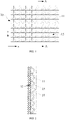
FIG. 1 is a top view of a partial structure of a microstructure layer of a projection screen according to a first embodiment of the present disclosure; -
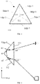
FIG. 2 is a cross-sectional view of the projection screen inFIG. 1 taken along direction A-A; -
FIG. 3 is a perspective view of a triangular pyramid unit shown inFIG. 1 ; -
FIG. 4 is a side view of the triangular pyramid unit inFIG. 3 in a vertical viewing direction; -
FIG. 5 is a side view of the triangular pyramid unit inFIG. 3 in a horizontal viewing direction; -
FIG. 6 is a schematic diagram of a partial structure of the projection screen shown inFIG. 2 ; -
FIG. 7 is a schematic diagram of vertical transmission of image light projected to the projection screen shown inFIG. 1 ; -
FIG. 8 is a schematic diagram of horizontal transmission of image light projected to the projection screen shown inFIG. 1 ; and -
FIG. 9 is a top view of a partial structure of a projection screen according to a second embodiment of the present disclosure. - The objective of the present disclosure is as follows: for a projection screen including multiple triangular pyramid units arranged in an array, taper angles of the triangular pyramid units vary gradually, so that image light transmitted from a projector is reflected by a microstructure layer having the triangular pyramid units and then converged in a range centered around human eyes, to reduce brightness differences at different viewing positions, thereby ensuring high brightness uniformity and high gain of the projection screen. In this way, both good brightness uniformity and high gain are achieved.
- Based on the objective above, the following clearly and completely describes the technical solutions in the embodiments of the present disclosure with reference to the accompanying drawings in the embodiments of the present disclosure. It is understandable that the specific embodiments described herein are merely intended to explain the present disclosure, rather than to limit the present disclosure. The following embodiments and technical features in the embodiments can be combined with each other when there is no conflict therebetween. It should also be understood that, for convenience of description, only a partial structure related to the present disclosure rather than all the structure is shown in the accompany drawings. All other embodiments obtained by the person of ordinary skill in the art based on the embodiments of the present disclosure without creative efforts should fall within the protection scope of the present disclosure.
-
FIG. 1 is a top view of a partial structure of a microstructure layer of a projection screen according to a first embodiment of the present disclosure.FIG. 2 is a cross-sectional view of the projection screen inFIG. 1 taken along direction A-A. Referring toFIG. 1 and FIG. 2 , the microstructure layer of theprojection screen 10 includes amatrix layer 12 and a microstructure unit formed on a surface of thematrix layer 12, and the microstructure unit includes multipletriangular pyramid units 11 arranged in an array. -
FIG. 3 is a perspective view of atriangular pyramid unit 11 shown inFIG. 1 . Referring toFIG. 1 to FIG. 3 , a singletriangular pyramid unit 11 includes six straight edges:edge 1,edge 2,edge 3,edge 4,edge 5, andedge 6. Theedge 4, theedge 5, and theedge 6 are connected end to end sequentially to form a triangularfirst surface 111; theedge 2, theedge 3, and theedge 5 are connected end to end sequentially to form a triangularsecond surface 112; theedge 1, theedge 2, and theedge 4 are connected end to end sequentially to form a triangularthird surface 113; and theedge 1, theedge 3, and theedge 6 are connected end to end sequentially to form a triangularfourth surface 114. -
FIG. 4 is a side view of thetriangular pyramid unit 11 inFIG. 3 in a vertical viewing direction. Referring toFIG. 3 and FIG. 4 , an angle between theedge 1 and thefirst surface 111 is a vertex angle of thetriangular pyramid unit 11, and an angle θ between theedge 1 and thesecond surface 112 is a taper angle of thetriangular pyramid unit 11.FIG. 5 is a side view of thetriangular pyramid unit 11 inFIG. 3 in a horizontal viewing direction. Referring toFIG. 3 andFIG. 5 , an angle β between thethird surface 113 and thefourth surface 114 is a span angle of thetriangular pyramid unit 11. - Referring to
FIG. 1 to FIG. 5 , thefirst surfaces 111 of alltriangular pyramid units 11 are located in a same plane, for example, being located on amatrix layer 12 with a uniform thickness. The taper angles θ of alltriangular pyramid units 11 face towards a same side. Alltriangular pyramid units 11 arranged along a first direction D1 (e.g., a horizontal direction x shown inFIG. 1 ) are identical, which indicates that structures and arrangement patterns thereof are identical to each other. That is, the taper angles θ of thetriangular pyramid units 11 arranged along the first direction D1 are also the same. The taper angles θ of thetriangular pyramid units 11 arranged along a second direction D2 (e.g., a vertical direction y shown inFIG. 1 ) are different. - In the present disclosure, referring to
FIG. 3, FIG. 4 , andFIG. 5 , after image light transmitted from a projector is incident on theprojection screen 10, the image light is refracted by thefirst surface 111 and then irradiated to thesecond surface 112. A part of light reflected by the second surface 112 (a light component in the horizontal direction as shown inFIG. 5 ) is irradiated to thefourth surface 114, reflected by thefourth surface 114, and transmitted by thefirst surface 111 to human eyes. Another part of light reflected by the third surface 113 (a light component in the vertical direction as shown inFIG. 4 ) is irradiated to thefirst surface 111 and transmitted by thefirst surface 111 to the human eyes. Similarly, a part of light reflected by the fourth surface 114 (e.g., a light component in the horizontal direction) is irradiated to thethird surface 113, reflected by thethird surface 113, and transmitted by thefirst surface 111 to the human eyes; another part of light reflected by the fourth surface 114 (e.g., a light component in the vertical direction) is irradiated to thefirst surface 111 and transmitted by thefirst surface 111 to the human eyes. Thefirst surface 111 not only serves as a light incident surface of the projection screen 101, but also serves as a light output surface of theprojection screen 10. The image light is finally transmitted by thefirst surface 111 to the human eyes. - Based on this principle, in the
projection screen 10, provided that the taper angles θ of the multipletriangular pyramid units 11 arranged along the second direction D2 satisfy a preset relationship, the image light transmitted from the projector can be reflected by thetriangular pyramid units 11 and then converged in a range centered around the human eyes, to reduce brightness differences at different viewing positions, thereby ensuring high brightness uniformity and high gain of the projection screen. Specifically, - In the horizontal direction, when the projector is located at the lower half part of the
projection screen 10, assuming that the human eyes are at the middle position of theprojection screen 10, the taper angles θ gradually increase from bottom to top (withFIG. 4 andFIG. 6 as an example), so as to transmit as much image light to the position of the human eyes as possible. - In the horizontal direction, when the projector is located at the upper half part of the
projection screen 10, still assuming that the human eyes are at the middle position of theprojection screen 10, the taper angles θ gradually increase from top to bottom (withFIG. 4 as an example), so as to transmit as much image light to the position of the human eyes as possible. - According to an image light transmission path indicated by the arrow in
FIG. 4 (it should be understood that the image light transmission path shown inFIG. 4 is not an actual image light transmission path; sizes of incident angles and reflection angles of the image light at various interfaces are not in the relationship shown inFIG. 4; and FIG. 4 merely illustrates an angle variation trend of the taper angles θ in the case of different incident angles and reflection angles), thetriangular pyramid unit 11 satisfies the following relational expressions:


triangular pyramid unit 11, α1 denotes an incident angle of the image light when it is transmitted to thefirst surface 111 during incidence, α2 denotes a refraction angle of the image light after it is refracted by thefirst surface 111 during incidence, α3 denotes an incident angle of the image light when it is transmitted to thefirst surface 111 during emergence, α4 denotes an emergent angle of the image light, and n denotes a refractive index of thetriangular pyramid unit 11. - The following
relational expression 1 can be derived from the above three relational expressions:
- In other words, provided that the taper angles θ of the
triangular pyramid units 11 arranged along the second direction D2 satisfyrelational expression 1, in the vertical direction y, the incident angles α1 and the emergent angles α4 change continuously between adjacent triangular pyramid microstructures, and working angles (i.e., taper angles) θ of adjacent triangular pyramid microstructures on theprojection screen 10 also change continuously. That is, as shown inFIG. 6 , the taper angles θ1, θ2 and θ3 of three adjacenttriangular pyramid units 11 in the vertical direction change continuously according torelational expression 1. - When the projector is located at the lower half part of the
projection screen 10, assuming that the human eyes are at the middle position of theprojection screen 10 and light beams emitted by the projector are cone-shaped, thetriangular pyramid unit 11 at the lowermost of theprojection screen 10 has a minimum incident angle α1 and a maximum emergent angle α4, and thetriangular pyramid units 11 located at higher positions of theprojection screen 10 have gradually increasing incident angles α1 and gradually decreasing emergent angles α4. The incident angle α1 and the emergent angle α4 vary within a range of 0°-90°, that is, gradually increases and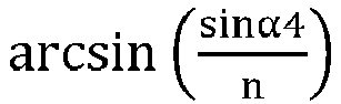

- As can be seen, the taper angles θ increase gradually from bottom to top of the
projection screen 10. - When the projector is located at the upper half part of the
projection screen 10, assuming that the human eyes are at the middle position of theprojection screen 10 and light beams emitted by the projector are cone-shaped, thetriangular pyramid unit 11 at the uppermost of theprojection screen 10 has a minimum incident angle α1 and a maximum emergent angle α4, and thetriangular pyramid units 11 located at lower positions of theprojection screen 10 have gradually increasing incident angles α1 and gradually decreasing emergent angles α4. The incident angle α1 and the emergent angle α4 vary within a range of 0-90°, that is,


- As can be seen, the taper angles θ decrease gradually from bottom to top of the
projection screen 10. - It can be learned from the above that, in the vertical direction y of the
projection screen 10, by setting different working angles θ at different height positions, all image light transmitted from the projector to different positions of theprojection screen 10 can be converged within the range where the human eyes are located, as shown inFIG. 7 . - In an actual scenario, both the
third surface 113 and thefourth surface 114 of thetriangular pyramid unit 11 are treated with physical vapor deposition (PVD) to achieve a surface reflectivity of 88%. With this implementation scenario as an example, as a viewer moves away from the central position of theprojection screen 10 in the horizontal direction, i.e., as a horizontal viewing angle changes, the brightness uniformity of theprojection screen 10 is maintained at 80% or above, while the brightness uniformity of the projection screen 20 in related art is maintained at 30% or lower. As can be seen, the brightness uniformity of theprojection screen 10 is much higher than the brightness uniformity of the projection screen 20 in related art. In this case, the gain of theprojection screen 10 is 4.9, which is much higher than the gain of 1, thus achieving high gain. - To improve the light reflection efficiency, the
second surface 112, thethird surface 113, and thefourth surface 114 of thetriangular pyramid unit 11 can be coated with a reflective material. The reflective coating can be a mixture of a metal reflective material, such as aluminum and silver, and other additives. The additives include a certain proportion of mixture of a leveling agent, a wetting agent, a defoaming agent and the like that are used to improve a coating effect, or a certain proportion of mixture of anhydrous acetone, anhydrous xylene, anhydrous cyclohexanone, anhydrous butanone, ethyl acetate and anhydrous butyl acetate, and the like. Depending on the actual application scenario, an appropriate diffusion material can also be added to the reflective coating to enhance the diffusion effect. The diffusion material includes, but not limited to, epoxy, acrylic or silicone organic resin particles, or other inorganic scattering materials. - Further referring to
FIG. 5 , in the horizontal direction x, the span angle β is an angle between thethird surface 113 and thefourth surface 114, and the value of β is in a range of 90°±20°. When β=90°, after the image light transmitted from the projector is incident on theprojection screen 10, the image light is reflected by thethird surface 113 and thefourth surface 114, to be transmitted to thefirst surface 111, and then refracted back to the projector in a direction the same as the incident direction. As shown inFIG. 8 , at different positions in the horizontal direction, the image light transmitted from the projector to different positions of theprojection screen 10 all return back to the projector along the original paths. When β≠90°, the image light transmitted from the projector to different positions of theprojection screen 10 cannot return to the projector along the original paths, but becomes a focal line in the horizontal direction of the observing plane. It is assumed that δ=90°-β, where a greater absolute value of δ corresponds to a longer focal line. - Referring to
FIG. 2 again, theprojection screen 10 can include adiffusion layer 12, areflective layer 13, and aprotective layer 14, and can include any combination thereof. The array of thetriangular pyramid units 11 forms an optical structure layer of theprojection screen 10. The optical structure layer can be prepared by heat embossing or UV glue transfer on atransparent substrate 12. Thetransparent substrate 12 includes, but not limited to, organic materials such as polyethylene terephthalate (PET), polycarbonate (PC), polyvinyl chloride (PVC), polymethyl methacrylate (PMMA), etc. Thesubstrate 12 can be formed by adiffusion layer 12 with a uniform thickness. The thickness of thediffusion layer 12 can be 100 µm to 1000 µm, and thediffusion layer 12 can be made of epoxy, acrylic or silicone organic resin particles, or other inorganic scattering materials. Herein, the optical structure layer is attached and fixed to thediffusion layer 12, and thefirst surfaces 111 of thetriangular pyramid units 11 are attached to and fixed to thediffusion layer 12. Thereflective layer 13 covers the optical structure layer. Thereflective layer 13 can be doped with scattering particles for scattering light, to enhance the light scattering effect. Theprotective layer 14 covers the outermost side of theprojection screen 10. Theprotective layer 14 can be prepared by using a water and oxygen barrier material, to project the internal structure. - The
diffusion layer 12, the optical structure layer, thereflective layer 13, and theprotective layer 14 can be attached and fixed together through a glue, to jointly form theprojection screen 10 with high gain and high brightness uniformity. - Referring to
FIG. 1 again, a region between two adjacenttriangular pyramid units 11 arranged along the horizontal direction x is alight transmission region 15. In other words, half region of the optical structure layer in this embodiment is provided with triangular pyramid microstructures, and the other half region is vacant. In this way, theprojection screen 10 of this embodiment is applicable to scenarios where both a foreground image and background content need to be displayed. - Different from the foregoing embodiment, a black coating layer can be provided in a vacant region of the microstructure unit, that is, in a region between two adjacent
triangular pyramid units 11 in the same row. The black coating layer is configured to absorb light irradiated thereon. Therefore, light from the back of the projection screen 10 (which can be regarded as ambient light) can be absorbed by the black coating layer, so that theprojection screen 10 has high resistance against ambient light, and is applicable to scenarios where it is unnecessary to see the background. - The
projection screen 10 can also be provided with other opaque structures in the region between two adjacenttriangular pyramid units 11 in a same row. Light from the back of theprojection screen 10 can be shielded by the opaque structure, so that theprojection screen 10 of this embodiment has high resistance against ambient light, and is applicable to scenarios where it is unnecessary to see the background. - Different from the foregoing embodiment, an optical coating layer can be provided in a region between two adjacent
triangular pyramid units 11 in a same row. The optical coating layer can comprise a metal reflective material, a black absorption material, other additives, and a diffusion material, and proportions of the materials of the reflective coating can be adjusted according to actual requirements, to adjust the light transmittance and light reflectivity of the optical coating layer 162. The optical coating layer 162 not only has a light absorbing capability, but also has light reflection and light diffusion capabilities. Therefore, theprojection screen 10 not only has high resistance against ambient light to be applicable to scenarios where it is unnecessary to see the background, but also has the light reflection and light diffusion capabilities to improve the intensity of light transmitted to human eyes, thus achieving high gain. - FIG. 11 is a top view of a partial structure of a projection screen according to a second embodiment of the present disclosure. As shown in FIG. 11, different from the foregoing embodiment shown in
FIG. 1 , ananti-structure prism 17 is provided between two adjacenttriangular pyramid units 11 that are arranged in a same row; in a direction of view perpendicular to theprojection screen 10, although any one of thetriangular pyramid units 11 is centrally symmetrical to a neighboringanti-structure prism 17, thefirst surface 111 of thetriangular pyramid unit 11 and the first surface of theanti-structure prism 17 face towards a same direction. In this way, the vertex angles of thetriangular pyramid units 11 and the vertex angles of theanti-structure prisms 17 face towards opposite directions. For example, as shown in FIG. 11, the vertex angles of thetriangular pyramid units 11 face upwards, while the vertex angles of theanti-structure prisms 17 face downwards. - That is, the
first surfaces 111 of thetriangular pyramid units 11 and the first surfaces of theanti-structure prisms 17 all face towards the projector. In other words, in the same row, thetriangular pyramid units 11 and theanti-structure prisms 17 are sequentially arranged in a staggered manner and are centrally symmetrical to each other. - It should be understood that, the
first surfaces 111 of all thetriangular pyramid units 11 are located in a same plane, for example, being located on a right side surface of thematrix layer 12 as shown inFIG. 2 ; and the first surfaces of allanti-structure prisms 17 are also located in a same plane, for example, being located on the right side surface of thematrix layer 12 as shown inFIG. 2 . Based on the foregoing configuration of thetriangular pyramid units 11 and theanti-structure prisms 17, the taper angles θ of allanti-structure prisms 17 satisfy the following relationship. - In the horizontal direction, when the projector is located at the lower half part of the
projection screen 10, assuming that the human eyes are at the middle position of theprojection screen 10, the taper angles θ of thetriangular pyramid units 11 gradually increase from bottom to top (withFIG. 4 as an example), so as to transmit as much image light to the position of the human eyes as possible. As can be seen, when the projector is located below theprojection screen 10, the image light is converged in a range centered around the human eyes after being reflected by thetriangular pyramid units 11, to reduce brightness differences at different viewing positions, thereby ensuring good uniformity and high gain of theprojection screen 10. - In the horizontal direction, when the projector is located at the upper half part of the
projection screen 10, still assuming that the human eyes are at the middle position of theprojection screen 10, the taper angles of theanti-structure prisms 17 increase gradually from top to bottom, and the taper angles of theanti-structure prisms 17 from top to bottom also satisfy the foregoingrelational expression 1, so as to transmit as much image light to the position of the human eyes as possible. As can be seen, when the projector is located above theprojection screen 10, the image light is converged in a range centered around the human eyes after being reflected by theanti-structure prisms 17, to reduce brightness differences at different viewing positions, thereby also ensuring good uniformity and high gain of theprojection screen 10. - In the horizontal direction, when the projector is located at the lower half part of the
projection screen 10, assuming that the human eyes are at the middle position of theprojection screen 10, the taper angles θ of thetriangular pyramid units 11 gradually increase from bottom to top (withFIG. 4 as an example), so as to transmit as much image light to the position of the human eyes as possible. As can be seen, when the projector is located below theprojection screen 10, the image light is converged in a range centered around the human eyes after being reflected by thetriangular pyramid units 11, to reduce brightness differences at different viewing positions, thereby ensuring good uniformity and high gain of theprojection screen 10. - In conclusion, whether the projector is located above or below the
projection screen 10, theprojection screen 10 can have high brightness uniformity and high gain. - In another embodiment, an
anti-structure prism 17 is provided between two adjacenttriangular pyramid units 11 arranged in a same row. The structure of theanti-structure prism 17 is the same as the structure of thetriangular pyramid unit 11. In a direction of view perpendicular to theprojection screen 10, any one of thetriangular pyramid units 11 is centrally symmetrical to a neighboringanti-structure prism 17, but thefirst surface 111 of thetriangular pyramid unit 11 and the first surface of the neighboringanti-structure prism 17 face towards the opposite directions. That is, thefirst surface 111 of thetriangular pyramid unit 11 faces towards the projector, while the first surface of theanti-structure prism 17 is back to the projector. In this way, both surfaces of theprojection screen 10 can achieve high brightness uniformity and high gain. - It should be understood that, described above are merely embodiments of the present disclosure, which do not limit the scope of the patent of the present disclosure. Any equivalent structure or equivalent process change made based on the description and drawings of the present disclosure, such as combination of technical features between different embodiments, or direct or indirect application thereof in other related technical fields, should still fall in the protection scope of the patent of the present disclosure.
- It should be understood that, the terms such as "first" and "second" in the present disclosure are used only for the purpose of description and cannot be understood as indicating or implying relative importance or implicitly indicating the number of technical features denoted. Therefore, features defined by "first" and "second" may explicitly or implicitly include at least one of the features. The term "multiple" indicates at least two, for example, two or three, unless otherwise clearly and specifically limited. All the directional indications (such as upper, lower, left, right, front, back, etc.) in the embodiments of the present disclosure are merely used to explain a relative position relationship, motion situations, and the like of the components in a specific gesture (as shown in the figures). If the specific gesture changes, the directivity indication also changes accordingly.
Claims (11)
- A projection screen, comprising:a microstructure layer comprising a matrix layer and a microstructure unit formed on a surface of the matrix layer,wherein the microstructure unit comprises triangular pyramid units arranged in an array, wherein each of the triangular pyramid units comprises a light output surface attached to and fixed to the surface of the matrix layer; wherein at least two of the triangular pyramid units that are arranged along a first direction are identical; wherein taper angles of at least two triangular pyramid units of the triangular pyramid units that are arranged along a second direction perpendicular to the first direction vary gradually; and wherein each of the taper angles forms between a base of one of the at least two triangular pyramid units that has the taper angle and an edge, parallel to the second direction, of the triangular pyramid unit, wherein the base is a surface of the triangular pyramid unit other than the light output surface and two surfaces that intersect to form the edge.
- The projection screen according to claim 1, wherein each of the taper angles of the at least two triangular pyramid units arranged along the second direction satisfy

- The projection screen according to claim 1, wherein a region between two adjacent triangular pyramid units, arranged along the first direction, of the triangular pyramid units is a light transmission region.
- The projection screen according to claim 1, wherein an opaque structure is disposed between two adjacent triangular pyramid units, arranged along the first direction, of the triangular pyramid units.
- The projection screen according to claim 1 or 4, wherein an optical coating layer is disposed between two adjacent triangular pyramid units of the triangular pyramid units in the first direction, and the optical coating layer comprises at least two of a reflective material, a light-absorbing material, or a light diffusion material.
- The projection screen according to claim 1, wherein one of anti-structure prisms is disposed between two adjacent triangular pyramid units of the triangular pyramid units that are arranged along the first direction; wherein the anti-structure prisms have a same structure as the triangular pyramid units, and each of the triangular pyramid units is centrally symmetrical with one of the anti-structure prisms that is adjacent to the triangular pyramid unit; and wherein the light output surface of one triangular pyramid unit of the triangular pyramid units and a light output surface of one of the anti-structure prisms that is adjacent to the one triangular pyramid unit face towards a same direction.
- The projection screen according to claim 1, wherein an angle between two surfaces that intersect each other to form the edge is within a value range of 90°±20°.
- The projection screen according to any one of claims 1 to 7, further comprising at least two of a diffusion layer, a reflective layer, or a protective layer; wherein the microstructure unit is disposed on the diffusion layer, and the light output surface of each of the triangular pyramid units is attached to and fixed to the diffusion layer; and wherein the reflective layer covers the microstructure unit, and the protective layer covers an outermost side of the projection screen.
- The projection screen according to claim 8, wherein the reflective layer is doped with scattering particles for scattering light.
- The projection screen according to claim 8, wherein the diffusion layer is a layer structure with a uniform thickness, and the diffusion layer is the matrix layer of the projection screen.
- The projection screen according to claim 10, wherein the thickness of the diffusion layer ranges from 100 µm to 1000 µm.
Applications Claiming Priority (2)
| Application Number | Priority Date | Filing Date | Title |
|---|---|---|---|
| CN201910605057.7A CN112180673B (en) | 2019-07-05 | 2019-07-05 | Projection screen |
| PCT/CN2020/098466 WO2021004303A1 (en) | 2019-07-05 | 2020-06-28 | Projection screen |
Publications (3)
| Publication Number | Publication Date |
|---|---|
| EP3985436A1 true EP3985436A1 (en) | 2022-04-20 |
| EP3985436A4 EP3985436A4 (en) | 2022-08-17 |
| EP3985436B1 EP3985436B1 (en) | 2024-03-27 |
Family
ID=73915382
Family Applications (1)
| Application Number | Title | Priority Date | Filing Date |
|---|---|---|---|
| EP20837041.1A Active EP3985436B1 (en) | 2019-07-05 | 2020-06-28 | Projection screen |
Country Status (4)
| Country | Link |
|---|---|
| US (1) | US11892766B2 (en) |
| EP (1) | EP3985436B1 (en) |
| CN (1) | CN112180673B (en) |
| WO (1) | WO2021004303A1 (en) |
Families Citing this family (5)
| Publication number | Priority date | Publication date | Assignee | Title |
|---|---|---|---|---|
| CN112180672A (en) * | 2019-07-05 | 2021-01-05 | 深圳光峰科技股份有限公司 | Projection screen |
| CN112180673B (en) * | 2019-07-05 | 2023-06-16 | 深圳光峰科技股份有限公司 | Projection screen |
| CN115706822B (en) * | 2021-08-17 | 2025-09-30 | 华为技术有限公司 | Screen projection method, screen projection system and first electronic device |
| CN116449641B (en) * | 2022-01-06 | 2025-10-17 | 深圳光峰科技股份有限公司 | Projection screen and projection system |
| CN116449640B (en) * | 2022-01-06 | 2025-09-30 | 深圳光峰科技股份有限公司 | Projection screens and projection systems |
Family Cites Families (22)
| Publication number | Priority date | Publication date | Assignee | Title |
|---|---|---|---|---|
| KR20010018578A (en) * | 1999-08-20 | 2001-03-05 | 성재갑 | Transformed Cube Corner Retroreflector Frustrated-Total-Internal-Reflecting Incident Rays and Method of Processing thereof |
| JP2006145881A (en) * | 2004-11-19 | 2006-06-08 | Olympus Corp | Reflection type projection screen |
| US7667893B2 (en) * | 2005-04-06 | 2010-02-23 | Seiko Epson Corporation | Microlens front projection screen |
| CN1928699A (en) * | 2005-11-24 | 2007-03-14 | 长春百泰精密光学仪器技术有限责任公司 | Suspension image projector |
| CN203587956U (en) * | 2013-09-16 | 2014-05-07 | 吴震 | Screen and projection display system |
| CN204009335U (en) * | 2014-07-21 | 2014-12-10 | 成都菲斯特科技有限公司 | The optical projection system of a kind of short projection distance forward projection optical screen |
| CN104076589A (en) * | 2014-07-21 | 2014-10-01 | 成都菲斯特科技有限公司 | Positive projection optical screen projection system short in projection distance |
| CN106406012A (en) | 2016-06-28 | 2017-02-15 | 张家港宝视特影视器材有限公司 | High-brightness curtain |
| CN109804297B (en) * | 2016-08-03 | 2021-09-07 | 米拉维兹公司 | Retroreflective screen, display system and method of displaying images |
| CN108663821A (en) | 2016-10-16 | 2018-10-16 | 王德龙 | A kind of 3D stereoprojections film |
| JP2018077379A (en) | 2016-11-10 | 2018-05-17 | 大日本印刷株式会社 | Molded sheet for producing retroreflective artificial leather sheet |
| CN109388014B (en) * | 2017-08-04 | 2021-07-06 | 深圳光峰科技股份有限公司 | Projection Screens and Projection Systems |
| CN109388015B (en) * | 2017-08-04 | 2024-05-17 | 深圳光峰科技股份有限公司 | Total reflection screen and projection system |
| CN109388013B (en) * | 2017-08-04 | 2022-02-11 | 深圳光峰科技股份有限公司 | Projection screen and projection system |
| TWI756466B (en) * | 2017-08-29 | 2022-03-01 | 美商艾維利 丹尼森公司 | Retroreflective sheeting for projector-based display system |
| CN207895098U (en) | 2017-11-29 | 2018-09-21 | 佛山市顺德区德联邦盛光电科技有限公司 | A kind of diffuser plate of Multilayer Density |
| CN110297387A (en) * | 2018-03-22 | 2019-10-01 | 深圳光峰科技股份有限公司 | Screen and optical projection system |
| CN110955106B (en) * | 2018-09-27 | 2021-11-12 | 深圳光峰科技股份有限公司 | Projection screen and projection system |
| CN111208705B (en) * | 2018-11-05 | 2022-04-22 | 深圳光峰科技股份有限公司 | Projection Screens and Projection Systems |
| CN109634046B (en) | 2018-12-24 | 2024-03-19 | 宁波激智科技股份有限公司 | Optical screen and preparation method thereof |
| CN112180673B (en) * | 2019-07-05 | 2023-06-16 | 深圳光峰科技股份有限公司 | Projection screen |
| CN112180672A (en) * | 2019-07-05 | 2021-01-05 | 深圳光峰科技股份有限公司 | Projection screen |
-
2019
- 2019-07-05 CN CN201910605057.7A patent/CN112180673B/en active Active
-
2020
- 2020-06-28 EP EP20837041.1A patent/EP3985436B1/en active Active
- 2020-06-28 WO PCT/CN2020/098466 patent/WO2021004303A1/en not_active Ceased
- 2020-06-28 US US17/597,434 patent/US11892766B2/en active Active
Also Published As
| Publication number | Publication date |
|---|---|
| WO2021004303A1 (en) | 2021-01-14 |
| US11892766B2 (en) | 2024-02-06 |
| CN112180673A (en) | 2021-01-05 |
| CN112180673B (en) | 2023-06-16 |
| EP3985436A4 (en) | 2022-08-17 |
| EP3985436B1 (en) | 2024-03-27 |
| US20220291579A1 (en) | 2022-09-15 |
Similar Documents
| Publication | Publication Date | Title |
|---|---|---|
| EP3985436B1 (en) | Projection screen | |
| EP3982198B1 (en) | Projection screen | |
| EP3663852B1 (en) | Total reflection screen and projection system | |
| KR100985358B1 (en) | Backlight | |
| CN207216263U (en) | Totally reflective screens and projection systems | |
| US20080304150A1 (en) | Screen and projection system using the same | |
| TW201723634A (en) | Projection screen | |
| TW201930925A (en) | Optical film and display module | |
| WO2019024367A1 (en) | Projection screen and projection system | |
| US11448952B2 (en) | Screen and projection system | |
| KR0144686B1 (en) | Rear projection screen | |
| CN109388012B (en) | Projection Screens and Projection Systems | |
| EP3805860B1 (en) | Projection screen and projection system | |
| US10545399B2 (en) | Rear projection screen | |
| CN109388014B (en) | Projection Screens and Projection Systems | |
| WO2019179124A1 (en) | Screen and projection system | |
| CN113009769B (en) | Projection screen and projection device | |
| JP4515374B2 (en) | LIGHTING DEVICE AND DISPLAY DEVICE USING THE SAME | |
| US20190294037A1 (en) | Rear projection screen | |
| CN112824970B (en) | Direct projection screen | |
| CN106772711B (en) | Optical film | |
| JPH02136846A (en) | reflective screen |
Legal Events
| Date | Code | Title | Description |
|---|---|---|---|
| STAA | Information on the status of an ep patent application or granted ep patent |
Free format text: STATUS: THE INTERNATIONAL PUBLICATION HAS BEEN MADE |
|
| PUAI | Public reference made under article 153(3) epc to a published international application that has entered the european phase |
Free format text: ORIGINAL CODE: 0009012 |
|
| STAA | Information on the status of an ep patent application or granted ep patent |
Free format text: STATUS: REQUEST FOR EXAMINATION WAS MADE |
|
| 17P | Request for examination filed |
Effective date: 20220117 |
|
| AK | Designated contracting states |
Kind code of ref document: A1 Designated state(s): AL AT BE BG CH CY CZ DE DK EE ES FI FR GB GR HR HU IE IS IT LI LT LU LV MC MK MT NL NO PL PT RO RS SE SI SK SM TR |
|
| A4 | Supplementary search report drawn up and despatched |
Effective date: 20220718 |
|
| RIC1 | Information provided on ipc code assigned before grant |
Ipc: G03B 21/602 20140101ALI20220712BHEP Ipc: G03B 21/60 20140101AFI20220712BHEP |
|
| DAV | Request for validation of the european patent (deleted) | ||
| DAX | Request for extension of the european patent (deleted) | ||
| GRAP | Despatch of communication of intention to grant a patent |
Free format text: ORIGINAL CODE: EPIDOSNIGR1 |
|
| STAA | Information on the status of an ep patent application or granted ep patent |
Free format text: STATUS: GRANT OF PATENT IS INTENDED |
|
| RIC1 | Information provided on ipc code assigned before grant |
Ipc: G03B 21/602 20140101ALI20231130BHEP Ipc: G03B 21/60 20140101AFI20231130BHEP |
|
| INTG | Intention to grant announced |
Effective date: 20231215 |
|
| GRAS | Grant fee paid |
Free format text: ORIGINAL CODE: EPIDOSNIGR3 |
|
| GRAA | (expected) grant |
Free format text: ORIGINAL CODE: 0009210 |
|
| STAA | Information on the status of an ep patent application or granted ep patent |
Free format text: STATUS: THE PATENT HAS BEEN GRANTED |
|
| AK | Designated contracting states |
Kind code of ref document: B1 Designated state(s): AL AT BE BG CH CY CZ DE DK EE ES FI FR GB GR HR HU IE IS IT LI LT LU LV MC MK MT NL NO PL PT RO RS SE SI SK SM TR |
|
| REG | Reference to a national code |
Ref country code: GB Ref legal event code: FG4D |
|
| REG | Reference to a national code |
Ref country code: CH Ref legal event code: EP |
|
| REG | Reference to a national code |
Ref country code: DE Ref legal event code: R096 Ref document number: 602020028078 Country of ref document: DE |
|
| REG | Reference to a national code |
Ref country code: IE Ref legal event code: FG4D |
|
| PG25 | Lapsed in a contracting state [announced via postgrant information from national office to epo] |
Ref country code: LT Free format text: LAPSE BECAUSE OF FAILURE TO SUBMIT A TRANSLATION OF THE DESCRIPTION OR TO PAY THE FEE WITHIN THE PRESCRIBED TIME-LIMIT Effective date: 20240327 |
|
| REG | Reference to a national code |
Ref country code: LT Ref legal event code: MG9D |
|
| PG25 | Lapsed in a contracting state [announced via postgrant information from national office to epo] |
Ref country code: GR Free format text: LAPSE BECAUSE OF FAILURE TO SUBMIT A TRANSLATION OF THE DESCRIPTION OR TO PAY THE FEE WITHIN THE PRESCRIBED TIME-LIMIT Effective date: 20240628 |
|
| PG25 | Lapsed in a contracting state [announced via postgrant information from national office to epo] |
Ref country code: RS Free format text: LAPSE BECAUSE OF FAILURE TO SUBMIT A TRANSLATION OF THE DESCRIPTION OR TO PAY THE FEE WITHIN THE PRESCRIBED TIME-LIMIT Effective date: 20240627 Ref country code: HR Free format text: LAPSE BECAUSE OF FAILURE TO SUBMIT A TRANSLATION OF THE DESCRIPTION OR TO PAY THE FEE WITHIN THE PRESCRIBED TIME-LIMIT Effective date: 20240327 |
|
| PG25 | Lapsed in a contracting state [announced via postgrant information from national office to epo] |
Ref country code: RS Free format text: LAPSE BECAUSE OF FAILURE TO SUBMIT A TRANSLATION OF THE DESCRIPTION OR TO PAY THE FEE WITHIN THE PRESCRIBED TIME-LIMIT Effective date: 20240627 Ref country code: NO Free format text: LAPSE BECAUSE OF FAILURE TO SUBMIT A TRANSLATION OF THE DESCRIPTION OR TO PAY THE FEE WITHIN THE PRESCRIBED TIME-LIMIT Effective date: 20240627 Ref country code: LT Free format text: LAPSE BECAUSE OF FAILURE TO SUBMIT A TRANSLATION OF THE DESCRIPTION OR TO PAY THE FEE WITHIN THE PRESCRIBED TIME-LIMIT Effective date: 20240327 Ref country code: HR Free format text: LAPSE BECAUSE OF FAILURE TO SUBMIT A TRANSLATION OF THE DESCRIPTION OR TO PAY THE FEE WITHIN THE PRESCRIBED TIME-LIMIT Effective date: 20240327 Ref country code: GR Free format text: LAPSE BECAUSE OF FAILURE TO SUBMIT A TRANSLATION OF THE DESCRIPTION OR TO PAY THE FEE WITHIN THE PRESCRIBED TIME-LIMIT Effective date: 20240628 Ref country code: FI Free format text: LAPSE BECAUSE OF FAILURE TO SUBMIT A TRANSLATION OF THE DESCRIPTION OR TO PAY THE FEE WITHIN THE PRESCRIBED TIME-LIMIT Effective date: 20240327 Ref country code: BG Free format text: LAPSE BECAUSE OF FAILURE TO SUBMIT A TRANSLATION OF THE DESCRIPTION OR TO PAY THE FEE WITHIN THE PRESCRIBED TIME-LIMIT Effective date: 20240327 |
|
| REG | Reference to a national code |
Ref country code: NL Ref legal event code: MP Effective date: 20240327 |
|
| PG25 | Lapsed in a contracting state [announced via postgrant information from national office to epo] |
Ref country code: SE Free format text: LAPSE BECAUSE OF FAILURE TO SUBMIT A TRANSLATION OF THE DESCRIPTION OR TO PAY THE FEE WITHIN THE PRESCRIBED TIME-LIMIT Effective date: 20240327 Ref country code: LV Free format text: LAPSE BECAUSE OF FAILURE TO SUBMIT A TRANSLATION OF THE DESCRIPTION OR TO PAY THE FEE WITHIN THE PRESCRIBED TIME-LIMIT Effective date: 20240327 |
|
| PG25 | Lapsed in a contracting state [announced via postgrant information from national office to epo] |
Ref country code: NL Free format text: LAPSE BECAUSE OF FAILURE TO SUBMIT A TRANSLATION OF THE DESCRIPTION OR TO PAY THE FEE WITHIN THE PRESCRIBED TIME-LIMIT Effective date: 20240327 |
|
| REG | Reference to a national code |
Ref country code: AT Ref legal event code: MK05 Ref document number: 1670482 Country of ref document: AT Kind code of ref document: T Effective date: 20240327 |
|
| PG25 | Lapsed in a contracting state [announced via postgrant information from national office to epo] |
Ref country code: NL Free format text: LAPSE BECAUSE OF FAILURE TO SUBMIT A TRANSLATION OF THE DESCRIPTION OR TO PAY THE FEE WITHIN THE PRESCRIBED TIME-LIMIT Effective date: 20240327 |
|
| PG25 | Lapsed in a contracting state [announced via postgrant information from national office to epo] |
Ref country code: IS Free format text: LAPSE BECAUSE OF FAILURE TO SUBMIT A TRANSLATION OF THE DESCRIPTION OR TO PAY THE FEE WITHIN THE PRESCRIBED TIME-LIMIT Effective date: 20240727 |
|
| PG25 | Lapsed in a contracting state [announced via postgrant information from national office to epo] |
Ref country code: SM Free format text: LAPSE BECAUSE OF FAILURE TO SUBMIT A TRANSLATION OF THE DESCRIPTION OR TO PAY THE FEE WITHIN THE PRESCRIBED TIME-LIMIT Effective date: 20240327 Ref country code: PT Free format text: LAPSE BECAUSE OF FAILURE TO SUBMIT A TRANSLATION OF THE DESCRIPTION OR TO PAY THE FEE WITHIN THE PRESCRIBED TIME-LIMIT Effective date: 20240729 |
|
| PG25 | Lapsed in a contracting state [announced via postgrant information from national office to epo] |
Ref country code: ES Free format text: LAPSE BECAUSE OF FAILURE TO SUBMIT A TRANSLATION OF THE DESCRIPTION OR TO PAY THE FEE WITHIN THE PRESCRIBED TIME-LIMIT Effective date: 20240327 |
|
| PG25 | Lapsed in a contracting state [announced via postgrant information from national office to epo] |
Ref country code: CZ Free format text: LAPSE BECAUSE OF FAILURE TO SUBMIT A TRANSLATION OF THE DESCRIPTION OR TO PAY THE FEE WITHIN THE PRESCRIBED TIME-LIMIT Effective date: 20240327 Ref country code: EE Free format text: LAPSE BECAUSE OF FAILURE TO SUBMIT A TRANSLATION OF THE DESCRIPTION OR TO PAY THE FEE WITHIN THE PRESCRIBED TIME-LIMIT Effective date: 20240327 |
|
| PG25 | Lapsed in a contracting state [announced via postgrant information from national office to epo] |
Ref country code: AT Free format text: LAPSE BECAUSE OF FAILURE TO SUBMIT A TRANSLATION OF THE DESCRIPTION OR TO PAY THE FEE WITHIN THE PRESCRIBED TIME-LIMIT Effective date: 20240327 |
|
| PG25 | Lapsed in a contracting state [announced via postgrant information from national office to epo] |
Ref country code: PL Free format text: LAPSE BECAUSE OF FAILURE TO SUBMIT A TRANSLATION OF THE DESCRIPTION OR TO PAY THE FEE WITHIN THE PRESCRIBED TIME-LIMIT Effective date: 20240327 |
|
| PG25 | Lapsed in a contracting state [announced via postgrant information from national office to epo] |
Ref country code: SK Free format text: LAPSE BECAUSE OF FAILURE TO SUBMIT A TRANSLATION OF THE DESCRIPTION OR TO PAY THE FEE WITHIN THE PRESCRIBED TIME-LIMIT Effective date: 20240327 |
|
| PG25 | Lapsed in a contracting state [announced via postgrant information from national office to epo] |
Ref country code: SM Free format text: LAPSE BECAUSE OF FAILURE TO SUBMIT A TRANSLATION OF THE DESCRIPTION OR TO PAY THE FEE WITHIN THE PRESCRIBED TIME-LIMIT Effective date: 20240327 Ref country code: SK Free format text: LAPSE BECAUSE OF FAILURE TO SUBMIT A TRANSLATION OF THE DESCRIPTION OR TO PAY THE FEE WITHIN THE PRESCRIBED TIME-LIMIT Effective date: 20240327 Ref country code: RO Free format text: LAPSE BECAUSE OF FAILURE TO SUBMIT A TRANSLATION OF THE DESCRIPTION OR TO PAY THE FEE WITHIN THE PRESCRIBED TIME-LIMIT Effective date: 20240327 Ref country code: PT Free format text: LAPSE BECAUSE OF FAILURE TO SUBMIT A TRANSLATION OF THE DESCRIPTION OR TO PAY THE FEE WITHIN THE PRESCRIBED TIME-LIMIT Effective date: 20240729 Ref country code: PL Free format text: LAPSE BECAUSE OF FAILURE TO SUBMIT A TRANSLATION OF THE DESCRIPTION OR TO PAY THE FEE WITHIN THE PRESCRIBED TIME-LIMIT Effective date: 20240327 Ref country code: IS Free format text: LAPSE BECAUSE OF FAILURE TO SUBMIT A TRANSLATION OF THE DESCRIPTION OR TO PAY THE FEE WITHIN THE PRESCRIBED TIME-LIMIT Effective date: 20240727 Ref country code: ES Free format text: LAPSE BECAUSE OF FAILURE TO SUBMIT A TRANSLATION OF THE DESCRIPTION OR TO PAY THE FEE WITHIN THE PRESCRIBED TIME-LIMIT Effective date: 20240327 Ref country code: EE Free format text: LAPSE BECAUSE OF FAILURE TO SUBMIT A TRANSLATION OF THE DESCRIPTION OR TO PAY THE FEE WITHIN THE PRESCRIBED TIME-LIMIT Effective date: 20240327 Ref country code: CZ Free format text: LAPSE BECAUSE OF FAILURE TO SUBMIT A TRANSLATION OF THE DESCRIPTION OR TO PAY THE FEE WITHIN THE PRESCRIBED TIME-LIMIT Effective date: 20240327 Ref country code: AT Free format text: LAPSE BECAUSE OF FAILURE TO SUBMIT A TRANSLATION OF THE DESCRIPTION OR TO PAY THE FEE WITHIN THE PRESCRIBED TIME-LIMIT Effective date: 20240327 |
|
| PG25 | Lapsed in a contracting state [announced via postgrant information from national office to epo] |
Ref country code: IT Free format text: LAPSE BECAUSE OF FAILURE TO SUBMIT A TRANSLATION OF THE DESCRIPTION OR TO PAY THE FEE WITHIN THE PRESCRIBED TIME-LIMIT Effective date: 20240327 |
|
| PG25 | Lapsed in a contracting state [announced via postgrant information from national office to epo] |
Ref country code: IT Free format text: LAPSE BECAUSE OF FAILURE TO SUBMIT A TRANSLATION OF THE DESCRIPTION OR TO PAY THE FEE WITHIN THE PRESCRIBED TIME-LIMIT Effective date: 20240327 |
|
| REG | Reference to a national code |
Ref country code: DE Ref legal event code: R097 Ref document number: 602020028078 Country of ref document: DE |
|
| PG25 | Lapsed in a contracting state [announced via postgrant information from national office to epo] |
Ref country code: DK Free format text: LAPSE BECAUSE OF FAILURE TO SUBMIT A TRANSLATION OF THE DESCRIPTION OR TO PAY THE FEE WITHIN THE PRESCRIBED TIME-LIMIT Effective date: 20240327 |
|
| PG25 | Lapsed in a contracting state [announced via postgrant information from national office to epo] |
Ref country code: DK Free format text: LAPSE BECAUSE OF FAILURE TO SUBMIT A TRANSLATION OF THE DESCRIPTION OR TO PAY THE FEE WITHIN THE PRESCRIBED TIME-LIMIT Effective date: 20240327 Ref country code: MC Free format text: LAPSE BECAUSE OF FAILURE TO SUBMIT A TRANSLATION OF THE DESCRIPTION OR TO PAY THE FEE WITHIN THE PRESCRIBED TIME-LIMIT Effective date: 20240327 |
|
| REG | Reference to a national code |
Ref country code: CH Ref legal event code: PL |
|
| PLBE | No opposition filed within time limit |
Free format text: ORIGINAL CODE: 0009261 |
|
| STAA | Information on the status of an ep patent application or granted ep patent |
Free format text: STATUS: NO OPPOSITION FILED WITHIN TIME LIMIT |
|
| PG25 | Lapsed in a contracting state [announced via postgrant information from national office to epo] |
Ref country code: LU Free format text: LAPSE BECAUSE OF NON-PAYMENT OF DUE FEES Effective date: 20240628 |
|
| 26N | No opposition filed |
Effective date: 20250103 |
|
| PG25 | Lapsed in a contracting state [announced via postgrant information from national office to epo] |
Ref country code: IE Free format text: LAPSE BECAUSE OF NON-PAYMENT OF DUE FEES Effective date: 20240628 |
|
| PG25 | Lapsed in a contracting state [announced via postgrant information from national office to epo] |
Ref country code: SI Free format text: LAPSE BECAUSE OF FAILURE TO SUBMIT A TRANSLATION OF THE DESCRIPTION OR TO PAY THE FEE WITHIN THE PRESCRIBED TIME-LIMIT Effective date: 20240327 Ref country code: BE Free format text: LAPSE BECAUSE OF NON-PAYMENT OF DUE FEES Effective date: 20240630 Ref country code: CH Free format text: LAPSE BECAUSE OF NON-PAYMENT OF DUE FEES Effective date: 20240630 |
|
| REG | Reference to a national code |
Ref country code: BE Ref legal event code: MM Effective date: 20240630 |
|
| PGFP | Annual fee paid to national office [announced via postgrant information from national office to epo] |
Ref country code: DE Payment date: 20250618 Year of fee payment: 6 |
|
| PGFP | Annual fee paid to national office [announced via postgrant information from national office to epo] |
Ref country code: GB Payment date: 20250618 Year of fee payment: 6 |
|
| PGFP | Annual fee paid to national office [announced via postgrant information from national office to epo] |
Ref country code: FR Payment date: 20250627 Year of fee payment: 6 |
|
| PG25 | Lapsed in a contracting state [announced via postgrant information from national office to epo] |
Ref country code: CY Free format text: LAPSE BECAUSE OF FAILURE TO SUBMIT A TRANSLATION OF THE DESCRIPTION OR TO PAY THE FEE WITHIN THE PRESCRIBED TIME-LIMIT; INVALID AB INITIO Effective date: 20200628 |
|
| PG25 | Lapsed in a contracting state [announced via postgrant information from national office to epo] |
Ref country code: HU Free format text: LAPSE BECAUSE OF FAILURE TO SUBMIT A TRANSLATION OF THE DESCRIPTION OR TO PAY THE FEE WITHIN THE PRESCRIBED TIME-LIMIT; INVALID AB INITIO Effective date: 20200628 |