EP3985050A1 - Shim for disk brakes, and disk brake - Google Patents
Shim for disk brakes, and disk brake Download PDFInfo
- Publication number
- EP3985050A1 EP3985050A1 EP20827089.2A EP20827089A EP3985050A1 EP 3985050 A1 EP3985050 A1 EP 3985050A1 EP 20827089 A EP20827089 A EP 20827089A EP 3985050 A1 EP3985050 A1 EP 3985050A1
- Authority
- EP
- European Patent Office
- Prior art keywords
- shim
- rubber layer
- disc brake
- layer
- base material
- Prior art date
- Legal status (The legal status is an assumption and is not a legal conclusion. Google has not performed a legal analysis and makes no representation as to the accuracy of the status listed.)
- Granted
Links
Images



Classifications
-
- F—MECHANICAL ENGINEERING; LIGHTING; HEATING; WEAPONS; BLASTING
- F16—ENGINEERING ELEMENTS AND UNITS; GENERAL MEASURES FOR PRODUCING AND MAINTAINING EFFECTIVE FUNCTIONING OF MACHINES OR INSTALLATIONS; THERMAL INSULATION IN GENERAL
- F16D—COUPLINGS FOR TRANSMITTING ROTATION; CLUTCHES; BRAKES
- F16D69/00—Friction linings; Attachment thereof; Selection of coacting friction substances or surfaces
- F16D69/04—Attachment of linings
- F16D69/0408—Attachment of linings specially adapted for plane linings
-
- F—MECHANICAL ENGINEERING; LIGHTING; HEATING; WEAPONS; BLASTING
- F16—ENGINEERING ELEMENTS AND UNITS; GENERAL MEASURES FOR PRODUCING AND MAINTAINING EFFECTIVE FUNCTIONING OF MACHINES OR INSTALLATIONS; THERMAL INSULATION IN GENERAL
- F16D—COUPLINGS FOR TRANSMITTING ROTATION; CLUTCHES; BRAKES
- F16D65/00—Parts or details
- F16D65/02—Braking members; Mounting thereof
- F16D65/04—Bands, shoes or pads; Pivots or supporting members therefor
- F16D65/092—Bands, shoes or pads; Pivots or supporting members therefor for axially-engaging brakes, e.g. disc brakes
- F16D65/095—Pivots or supporting members therefor
- F16D65/097—Resilient means interposed between pads and supporting members or other brake parts
- F16D65/0971—Resilient means interposed between pads and supporting members or other brake parts transmitting brake actuation force, e.g. elements interposed between brake piston and pad
-
- B—PERFORMING OPERATIONS; TRANSPORTING
- B32—LAYERED PRODUCTS
- B32B—LAYERED PRODUCTS, i.e. PRODUCTS BUILT-UP OF STRATA OF FLAT OR NON-FLAT, e.g. CELLULAR OR HONEYCOMB, FORM
- B32B15/00—Layered products comprising a layer of metal
- B32B15/04—Layered products comprising a layer of metal comprising metal as the main or only constituent of a layer, which is next to another layer of the same or of a different material
- B32B15/043—Layered products comprising a layer of metal comprising metal as the main or only constituent of a layer, which is next to another layer of the same or of a different material of metal
-
- B—PERFORMING OPERATIONS; TRANSPORTING
- B32—LAYERED PRODUCTS
- B32B—LAYERED PRODUCTS, i.e. PRODUCTS BUILT-UP OF STRATA OF FLAT OR NON-FLAT, e.g. CELLULAR OR HONEYCOMB, FORM
- B32B15/00—Layered products comprising a layer of metal
- B32B15/04—Layered products comprising a layer of metal comprising metal as the main or only constituent of a layer, which is next to another layer of the same or of a different material
- B32B15/046—Layered products comprising a layer of metal comprising metal as the main or only constituent of a layer, which is next to another layer of the same or of a different material of foam
-
- B—PERFORMING OPERATIONS; TRANSPORTING
- B32—LAYERED PRODUCTS
- B32B—LAYERED PRODUCTS, i.e. PRODUCTS BUILT-UP OF STRATA OF FLAT OR NON-FLAT, e.g. CELLULAR OR HONEYCOMB, FORM
- B32B15/00—Layered products comprising a layer of metal
- B32B15/18—Layered products comprising a layer of metal comprising iron or steel
-
- B—PERFORMING OPERATIONS; TRANSPORTING
- B32—LAYERED PRODUCTS
- B32B—LAYERED PRODUCTS, i.e. PRODUCTS BUILT-UP OF STRATA OF FLAT OR NON-FLAT, e.g. CELLULAR OR HONEYCOMB, FORM
- B32B5/00—Layered products characterised by the non- homogeneity or physical structure, i.e. comprising a fibrous, filamentary, particulate or foam layer; Layered products characterised by having a layer differing constitutionally or physically in different parts
- B32B5/18—Layered products characterised by the non- homogeneity or physical structure, i.e. comprising a fibrous, filamentary, particulate or foam layer; Layered products characterised by having a layer differing constitutionally or physically in different parts characterised by features of a layer of foamed material
- B32B5/20—Layered products characterised by the non- homogeneity or physical structure, i.e. comprising a fibrous, filamentary, particulate or foam layer; Layered products characterised by having a layer differing constitutionally or physically in different parts characterised by features of a layer of foamed material foamed in situ
-
- F—MECHANICAL ENGINEERING; LIGHTING; HEATING; WEAPONS; BLASTING
- F16—ENGINEERING ELEMENTS AND UNITS; GENERAL MEASURES FOR PRODUCING AND MAINTAINING EFFECTIVE FUNCTIONING OF MACHINES OR INSTALLATIONS; THERMAL INSULATION IN GENERAL
- F16D—COUPLINGS FOR TRANSMITTING ROTATION; CLUTCHES; BRAKES
- F16D65/00—Parts or details
- F16D65/0006—Noise or vibration control
-
- F—MECHANICAL ENGINEERING; LIGHTING; HEATING; WEAPONS; BLASTING
- F16—ENGINEERING ELEMENTS AND UNITS; GENERAL MEASURES FOR PRODUCING AND MAINTAINING EFFECTIVE FUNCTIONING OF MACHINES OR INSTALLATIONS; THERMAL INSULATION IN GENERAL
- F16D—COUPLINGS FOR TRANSMITTING ROTATION; CLUTCHES; BRAKES
- F16D65/00—Parts or details
- F16D65/02—Braking members; Mounting thereof
- F16D65/04—Bands, shoes or pads; Pivots or supporting members therefor
- F16D65/092—Bands, shoes or pads; Pivots or supporting members therefor for axially-engaging brakes, e.g. disc brakes
-
- B—PERFORMING OPERATIONS; TRANSPORTING
- B32—LAYERED PRODUCTS
- B32B—LAYERED PRODUCTS, i.e. PRODUCTS BUILT-UP OF STRATA OF FLAT OR NON-FLAT, e.g. CELLULAR OR HONEYCOMB, FORM
- B32B2266/00—Composition of foam
- B32B2266/02—Organic
- B32B2266/0207—Materials belonging to B32B25/00
-
- B—PERFORMING OPERATIONS; TRANSPORTING
- B32—LAYERED PRODUCTS
- B32B—LAYERED PRODUCTS, i.e. PRODUCTS BUILT-UP OF STRATA OF FLAT OR NON-FLAT, e.g. CELLULAR OR HONEYCOMB, FORM
- B32B2307/00—Properties of the layers or laminate
- B32B2307/70—Other properties
- B32B2307/732—Dimensional properties
-
- B—PERFORMING OPERATIONS; TRANSPORTING
- B32—LAYERED PRODUCTS
- B32B—LAYERED PRODUCTS, i.e. PRODUCTS BUILT-UP OF STRATA OF FLAT OR NON-FLAT, e.g. CELLULAR OR HONEYCOMB, FORM
- B32B25/00—Layered products comprising a layer of natural or synthetic rubber
-
- B—PERFORMING OPERATIONS; TRANSPORTING
- B32—LAYERED PRODUCTS
- B32B—LAYERED PRODUCTS, i.e. PRODUCTS BUILT-UP OF STRATA OF FLAT OR NON-FLAT, e.g. CELLULAR OR HONEYCOMB, FORM
- B32B2605/00—Vehicles
-
- B—PERFORMING OPERATIONS; TRANSPORTING
- B32—LAYERED PRODUCTS
- B32B—LAYERED PRODUCTS, i.e. PRODUCTS BUILT-UP OF STRATA OF FLAT OR NON-FLAT, e.g. CELLULAR OR HONEYCOMB, FORM
- B32B27/00—Layered products comprising a layer of synthetic resin
- B32B27/06—Layered products comprising a layer of synthetic resin as the main or only constituent of a layer, which is next to another layer of the same or of a different material
- B32B27/065—Layered products comprising a layer of synthetic resin as the main or only constituent of a layer, which is next to another layer of the same or of a different material of foam
-
- B—PERFORMING OPERATIONS; TRANSPORTING
- B32—LAYERED PRODUCTS
- B32B—LAYERED PRODUCTS, i.e. PRODUCTS BUILT-UP OF STRATA OF FLAT OR NON-FLAT, e.g. CELLULAR OR HONEYCOMB, FORM
- B32B27/00—Layered products comprising a layer of synthetic resin
- B32B27/30—Layered products comprising a layer of synthetic resin comprising vinyl (co)polymers; comprising acrylic (co)polymers
- B32B27/308—Layered products comprising a layer of synthetic resin comprising vinyl (co)polymers; comprising acrylic (co)polymers comprising acrylic (co)polymers
-
- B—PERFORMING OPERATIONS; TRANSPORTING
- B32—LAYERED PRODUCTS
- B32B—LAYERED PRODUCTS, i.e. PRODUCTS BUILT-UP OF STRATA OF FLAT OR NON-FLAT, e.g. CELLULAR OR HONEYCOMB, FORM
- B32B27/00—Layered products comprising a layer of synthetic resin
- B32B27/40—Layered products comprising a layer of synthetic resin comprising polyurethanes
-
- B—PERFORMING OPERATIONS; TRANSPORTING
- B32—LAYERED PRODUCTS
- B32B—LAYERED PRODUCTS, i.e. PRODUCTS BUILT-UP OF STRATA OF FLAT OR NON-FLAT, e.g. CELLULAR OR HONEYCOMB, FORM
- B32B7/00—Layered products characterised by the relation between layers; Layered products characterised by the relative orientation of features between layers, or by the relative values of a measurable parameter between layers, i.e. products comprising layers having different physical, chemical or physicochemical properties; Layered products characterised by the interconnection of layers
- B32B7/04—Interconnection of layers
- B32B7/12—Interconnection of layers using interposed adhesives or interposed materials with bonding properties
-
- F—MECHANICAL ENGINEERING; LIGHTING; HEATING; WEAPONS; BLASTING
- F16—ENGINEERING ELEMENTS AND UNITS; GENERAL MEASURES FOR PRODUCING AND MAINTAINING EFFECTIVE FUNCTIONING OF MACHINES OR INSTALLATIONS; THERMAL INSULATION IN GENERAL
- F16D—COUPLINGS FOR TRANSMITTING ROTATION; CLUTCHES; BRAKES
- F16D69/00—Friction linings; Attachment thereof; Selection of coacting friction substances or surfaces
- F16D2069/005—Friction linings; Attachment thereof; Selection of coacting friction substances or surfaces having a layered structure
- F16D2069/007—Friction linings; Attachment thereof; Selection of coacting friction substances or surfaces having a layered structure comprising a resilient layer
-
- F—MECHANICAL ENGINEERING; LIGHTING; HEATING; WEAPONS; BLASTING
- F16—ENGINEERING ELEMENTS AND UNITS; GENERAL MEASURES FOR PRODUCING AND MAINTAINING EFFECTIVE FUNCTIONING OF MACHINES OR INSTALLATIONS; THERMAL INSULATION IN GENERAL
- F16D—COUPLINGS FOR TRANSMITTING ROTATION; CLUTCHES; BRAKES
- F16D69/00—Friction linings; Attachment thereof; Selection of coacting friction substances or surfaces
- F16D69/04—Attachment of linings
- F16D2069/0425—Attachment methods or devices
- F16D2069/045—Bonding
- F16D2069/0466—Bonding chemical, e.g. using adhesives, vulcanising
-
- F—MECHANICAL ENGINEERING; LIGHTING; HEATING; WEAPONS; BLASTING
- F16—ENGINEERING ELEMENTS AND UNITS; GENERAL MEASURES FOR PRODUCING AND MAINTAINING EFFECTIVE FUNCTIONING OF MACHINES OR INSTALLATIONS; THERMAL INSULATION IN GENERAL
- F16D—COUPLINGS FOR TRANSMITTING ROTATION; CLUTCHES; BRAKES
- F16D2200/00—Materials; Production methods therefor
- F16D2200/0034—Materials; Production methods therefor non-metallic
- F16D2200/0056—Elastomers
-
- F—MECHANICAL ENGINEERING; LIGHTING; HEATING; WEAPONS; BLASTING
- F16—ENGINEERING ELEMENTS AND UNITS; GENERAL MEASURES FOR PRODUCING AND MAINTAINING EFFECTIVE FUNCTIONING OF MACHINES OR INSTALLATIONS; THERMAL INSULATION IN GENERAL
- F16D—COUPLINGS FOR TRANSMITTING ROTATION; CLUTCHES; BRAKES
- F16D2250/00—Manufacturing; Assembly
- F16D2250/0061—Joining
- F16D2250/0069—Adhesive bonding
Definitions
- the present invention relates to a disc brake shim and a disc brake.
- Patent Literature 1 Japanese Patent Laid-Open No. 2010-31960 , for example.
- Figure 12 is a vertical sectional view in one exemplary mode of a disc brake.
- a disc brake B is structured such that it applies brakes by pressing brake pads 30 and 30 that are arranged on both sides in an axial direction of a disc rotor 60 that rotates integrally with a wheel, with a pressing member 70 formed of a piston and the like by hydraulic pressure of a brake oil 80 in a caliper 50, and pressing the brake pads 30 and 30 from both sides of the disc rotor 60.
- Patent Literature 1 Japanese Patent Laid-Open No. 2010-31960
- a shim S is interposed between a pad material P formed of the brake pad 30 and the back metal 40, and the pressing member 70, as illustrated in Figure 12 and Figure 13 .
- a rubber coat metal (RCM) with thin rubber layers 20 and 20 fixed onto surfaces of a metal sheet 10 that is formed of a joined material in which a stainless steel sheet and an iron sheet are bonded together as illustrated in Figure 12 and Figure 13 and it is considered that according to such a shim S, the vibration that is the cause of squeal can be dampened by using elasticity of the rubber layer 20 during a braking time by pressing by the pressing member 70.
- an object of the present invention is to provide a novel disc brake shim and disc brake that can effectively suppress vibration and squeal.
- the present inventors has found that the above described technical problem can be solved by a disc brake shim that is formed of a multilayer structure with three layers or more having at least a base material layer formed of a metal sheet, and a foamed rubber layer that is laminated on a main surface on one side of the base material layer, wherein the foamed rubber layer is an intermediate layer of the multilayer structure, and have completed the present invention based on the present findings.
- the present invention provides
- the foamed rubber layer provided on the base material layer hardly transmits vibration of the brake pads and the like because the foamed rubber layer has a low density with a foamed part, but also the foamed rubber layer deforms to follow the vibration of the brake pads and the like to easily convert the vibration into thermal energy because the foamed rubber layer has flexibility, and the foamed rubber layer can easily convert vibration of an external member into frictional heat because the foamed rubber layer further has a high friction coefficient.
- a disc brake shim according to the present invention is formed of a multilayer structure with three layers or more having at least a base material layer formed of a metal sheet, and a foamed rubber layer that is laminated and disposed on a main surface on one side of the base material layer, wherein the foamed rubber layer is disposed as an intermediate layer of the multilayer structure.
- the disc brake shim means the one in a state in which respective adjacent layers forming the disc brake shim are chemically or physically fixed.
- the metal sheet forming the base material layer is not particularly limited, but it is possible to cite sheet materials formed of a stainless steel (ferritic, martensitic, austenitic, and the like), iron, a plating material, aluminum and the like, and a sheet material formed of a stainless steel or iron is preferable.
- the metal sheet forming the base material layer may be formed by joining a plurality of metal sheets by pasting or the like, and as the metal sheet, a joined sheet of a stainless steel sheet and an iron sheet is preferable.
- a thickness of the metal sheet forming the base material layer is not particularly limited, but is normally 0.4 to 0.8 mm.
- the foamed rubber layer is preferably a foam of an unfoamed rubber layer.
- the foamed rubber layer is preferably a foam of an unfoamed rubber layer of a thickness of 15 to 100 ⁇ m, more preferably a foam of an unfoamed rubber layer of a thickness of 30 to 70 ⁇ m, and is even more preferably a foam of an unfoamed rubber layer of a thickness of 40 to 60 ⁇ m.
- a thickness of the above described unfoamed rubber layer means an arithmetic mean value when thicknesses at ten spots are measured by using a dial gauge.
- the thickness of the unfoamed rubber layer is within the above described range, so that the foamed rubber layer having a desired thickness can be easily formed.
- an expansion ratio of an unfoamed rubber layer is not particularly limited, but the foamed rubber layer is preferably a foam that is 2 to 4 times as large as the unfoamed rubber layer.
- expansion ratio foamed rubber layer thickness / unfoamed rubber layer thickness (Note that the thickness of the foamed rubber layer means the arithmetic mean value when the thicknesses at 10 spots are measured by using a dial gauge, and the thickness of the unfoamed rubber layer also means an arithmetic mean value when thicknesses at 10 spots are measured by using a dial gauge.)
- the expansion ratio of the unfoamed rubber layer is within the above described range, so that the foamed rubber layer having a desired thickness can be easily formed.
- the thickness of the foamed rubber layer is preferably 30 to 200 ⁇ m, more preferably 60 to 140 ⁇ m, and even more preferably 80 to 120 ⁇ m.
- the thickness of the foamed rubber layer is within the above described range, it is possible to easily provide the disc brake shim having a desired density, and having a desired flexibility and friction coefficient.
- a rubber composition forming the foamed rubber layer preferably contains a polymer (rubber component) having a Mooney value of 10 to 70, and more preferably contains a polymer having a Mooney value of 20 to 60.
- the Mooney value means a value that is measured by a method specified in JIS K6300-1 by using Mooney Viscometer SMV-201 made by Shimadzu Corporation.
- NBR nitrile rubber
- HNBR hydrogenated nitrile rubber
- EPDM ethylene propylene diene rubber
- NBR nitrile rubber
- HNBR hydrogenated nitrile rubber
- fluororubber ethylene propylene diene rubber
- NBR nitrile rubber
- a nitrile rubber with an AN value (content of acrylonitrile group in NBR) of 39 to 52 is preferable, and a nitrile rubber with an AN value of 40 to 48 is more preferable.
- the unfoamed robber layer contains the above described polymer, it is possible to easily obtain a foamed rubber layer having desired properties.
- the unfoamed rubber layer preferably contains 10 to 70% by mass of the above described polymer, more preferably 20 to 60% by mass of the above described polymer, and even more preferably 30 to 50% by mass of the above described polymer.
- the unfoamed rubber layer contains the above described polymer in the above described ratio, and thereby it is possible to effectively suppress sagging of the foamed rubber layer due to compression during braking.
- the foamed rubber layer is a foam of an unfoamed rubber layer
- such an unfoamed rubber layer preferably contains a heat-decomposable chemical foaming agent.
- heat-decomposable foaming agent a heat-decomposable foaming agent with a foaming temperature of 120°C or higher is preferable, and a heat-decomposable foaming agent with a foaming temperature of 150 to 210°C is more preferable.
- heat-decomposable foaming agent it is possible to cite one or more selected from, for example, an azodicarbonamide foaming agent, dinitrosopentamethylene tetramine foaming agent, oxybisbenzenesulfonylhydrazide foaming agent, sodium bicarbonate foaming agent and the like.
- the unfoamed rubber layer preferably contains 10 to 60% by mass of the above described heat-decomposable chemical foaming agent, and more preferably contains 15 to 35% by mass of the above described heat-decomposable chemical foaming agent.
- the unfoamed rubber layer contains the above described heat-decomposable chemical foaming agent in the above described ratio, and thereby it is possible to easily form the foamed rubber layer having a desired density, and having a desired flexibility and friction coefficient.
- the unfoamed rubber layer may contain a vulcanizing agent and a vulcanization accelerator.
- the vulcanizing agent is preferably contained in a large amount so as to increase a vulcanization density, and in the case of sulfur vulcanization, a sulfur compound amount is preferably 1.5 to 4.5 g (1.5 to 4.5 phr (parts per hundred rubber)) for 100 gram of polymer that is a rubber component.
- the vulcanization accelerator it is preferable to use a high-speed vulcanization accelerator that rises with a time to T50 within 4 minutes according to curast data (150°C).
- the time to T50 according to the curast data (150°) means a time required until a vulcanization degree of rubber reaches T50 (elapsed time until reaching 50% of maximum torque) when vulcanization is performed at 150°C by using a curast testing machine (JSR curast meter III made by Nichigo Shoji Co., Ltd.) .
- the foamed rubber layer preferably has a continuous foam rate of 60% or more, and more preferably has a continuous foam rate of 80% or more.
- the continuous foam rate means a value that is calculated by an expression below.
- replacement water weight (g) shown below means a value calculated by weight (g) after underwater replacement - weight (g) before underwater replacement treatment when treatment of immersing the disc brake shim having the above described foamed layer according to the present invention in water and thereafter performing vacuum-deaeration of the disc brake shim is repeated a plurality of times until the weight after underwater replacement becomes constant.
- volume of the foamed rubber layer means a value obtained from a product of a foamed rubber layer thickness obtained from an arithmetic mean value of thickness at 10 spots by using a dial gauge, and a surface area.
- volume of the unfoamed rubber layer also means a value obtained from a product of an unfoamed rubber layer thickness obtained from an arithmetic mean value of the thicknesses at 10 spots by using a dial gauge, and a surface area.
- Continuous foam rate % replaced water weight g / foamed rubber layer volume cm 3 ⁇ volume of rubber layer before foaming cm 3 ⁇ 100
- the continuous foam rate is within the above described range, and thereby it is possible to easily obtain a foamed rubber layer having a desired density, and having a desired flexibility and friction coefficient.
- the foamed rubber layer by, for example, dissolving a rubber compound containing respective desired amounts of polymer and a heat-decomposable chemical foaming agent in an organic solvent to prepare a coating liquid, applying the coating liquid to a metal sheet to be the base material layer, and fixing the coating liquid.
- the above described organic solvent is not limited as long as it can dissolve the above described rubber compound, but it is preferable to use an organic solvent prepared by mixing an ester solvent in a ratio of 10 to 90% by mass with respect to 10 to 90% by mass of aromatic hydrocarbon solvent (ketone type is also possible) such as toluene. Furthermore, as the coating liquid, a coating liquid that is prepared by dissolving the above described rubber compound in the above described organic solvent so that the solid content concentration is 10 to 60% by mass is preferable.
- a coating method of the coating liquid containing the rubber compound is not particularly limited, but the coating liquid is preferably coated by a skimmer coater, a roll coater or the like that can control a coating thickness.
- thermal treatment is preferably performed at 150 to 260°C for 5 to 15 minutes to foam the foaming agent, and a foamed rubber layer is fixed while being formed.
- foaming conditions such as a vulcanizing agent and the foaming agent to be used, a heating time and the like are adjusted so that the expansion ratio and the continuous foam rate of the foamed rubber layer to be obtained have desired values.
- the expansion ratio can be easily controlled by adjusting types and compound ratios of the polymer having the above described Mooney value, and the vulcanizing agent and the foaming agent described above, and can be easily controlled in particular by adjusting the Mooney value and a vulcanizing rate of the polymer.
- the expansion ratio increases, and when a polymer with a Mooney value of 20 to 40, a vulcanization accelerator at a low rate (curast data: a rising time to T50 in vulcanization at 150°C is around 5 to 6 minutes), and a foaming agent with a low foam decomposition temperature are combined, the expansion ratio increases, and when a polymer with a Mooney value of 40 to 60, a vulcanization accelerator with a high vulcanization rate (curast data: a rising time to T50 in vulcanization at 150°C is around 1 to 3 minutes), and a foaming agent with a high foam decomposition temperature are combined on the contrary, the expansion ratio is easily decreased.
- the disc brake shim according to the present invention is formed of a multilayer structure with three layers or more having at least a base material layer formed of a metal sheet, and a foamed rubber layer that is laminated and disposed on a main surface on one side of the base material layer, wherein the foamed rubber layer is disposed as an intermediate layer of the multilayer structure.
- the disc brake shim according to the present invention is formed of a multilayer structure with three layers or more, wherein the foamed rubber layer is disposed as an intermediate layer.
- the intermediate layer means a layer that is located on any one of locations on an inner side except for outermost layers, among a plurality of constituent layers that are three layers or more.
- the disc brake shim according to the present invention may have an adhesive layer, in addition to the base material layer formed of a metal sheet, and the foamed rubber layer that is laminated and disposed on the main surface on one side of the base material layer.
- an adhesive forming the adhesive layer it is possible to cite one or more selected from an acrylic adhesive, silicon adhesive, rubber adhesive, urethane adhesive and the like, and one or more selected from an acrylic adhesive and silicon adhesive is more preferable.
- the adhesive is an acrylic adhesive
- one or more selected from a metal chelate crosslinking agent, isocyanate crosslinking agent, epoxy crosslinking agent and the like is preferably further used as a crosslinking agent.
- the disc brake shim according to the present invention has the adhesive layer, and thereby can produce an excellent ability to prevent squeal by an excellent vibration control effect of the adhesive.
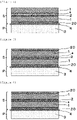
- Figure 1 is a vertical sectional view showing an exemplary mode of a disc brake shim according to the present invention having an adhesive layer.
- Figure 1 is a vertical sectional view showing the exemplary mode of a disc brake shim S that is formed of a multilayer structure with a three layers having a base material layer 1 formed of a metal sheet, a foamed rubber layer 2 that is laminated on a main surface on one side of the base material layer, and an adhesive layer "a" that is laminated on a main surface on an opposite side from the base material layer 1, of the foamed rubber layer 2, and as shown in Figure 1 , the disc brake shim S according to the present exemplary mode has the base material layer 1 and the adhesive layer "a" as outermost layers, and has the foamed rubber layer 2 as an intermediate layer between the base material layer 1 and the adhesive layer "a".
- the disc brake shim S in a braking time, is pressed (in a lower direction from an upper side in Figure 1 ) by a pressing member such as a piston that is provided in a caliper, and it is considered that not only the foamed rubber layer 2 forming the disc brake shim S hardly transmits vibration of the brake pad 3 and the like because the foamed rubber layer 2 has a low density with a foamed part, but also the foamed rubber layer 2 deforms to follow the vibration of the brake pad 3 and the like to easily convert the vibration into thermal energy because the foamed rubber layer 2 has flexibility.
- the disc brake shim according to the present invention may have a solid rubber layer, in addition to the base material layer formed of a metal sheet, and the foamed rubber layer that is laminated and disposed on the main surface on one side of the base material layer.
- the solid rubber layer means a rubber layer that is formed without going through a foaming step by a foaming agent and has no air bubbles (derived from a foaming agent).
- a thickness of the solid rubber layer is preferably 25 to 250 ⁇ m, more preferably 50 to 200 ⁇ m, and even more preferably 100 to 180 ⁇ m.
- the thickness of the above described solid rubber layer means an arithmetic mean value at a time of measuring thicknesses at 10 spots by using a dial gauge.
- nitrile rubber NBR
- HNBR hydrogenated nitrile rubber
- EPDM ethylene propylene diene rubber
- acrylic rubber acrylic rubber
- NBR nitrile rubber
- NBR hydrogenated nitrile rubber
- fluororubber ethylene propylene diene rubber
- NBR nitrile rubber
- a nitrile rubber with an AN value (content of acrylonitrile group in NBR) of 25 to 50 is preferable, and a nitrile rubber with an AN value of 30 to 45 is more preferable.
- the solid rubber layer may contain a vulcanizing agent and a vulcanization accelerator.
- the vulcanizing agent is preferably contained in a large amount so as to increase a vulcanization density, and in the case of sulfur vulcanization, a sulfur compound amount is preferably 1.5 to 4.5 g (1.5 to 4.5 phr (parts per hundred rubber)) for 100 gram of polymer that is a rubber component.
- a vulcanization accelerator it is preferable to use a vulcanization accelerator at a high rate with a time to T50 rising within 4 minutes according to curast data (150°C).
- the solid rubber layer by, for example, dissolving a rubber compound containing a desired amount of polymer in an organic solvent to prepare a coating liquid, applying the coating liquid to an object to be coated such as the base material layer, and fixing the coating liquid.
- the organic solvent is not limited as long as it can dissolve the above described rubber compound, but it is preferable to use an organic solvent prepared by mixing an ester solvent in a ratio of 10 to 90% by mass with respect to 10 to 90% by mass of aromatic hydrocarbon solvent (ketone type is also possible) such as toluene. Furthermore, as the coating liquid, a coating liquid that is prepared by dissolving the above described rubber compound in the above described organic solvent so that the solid content concentration is 10 to 60% by mass is preferable.
- a coating method of the coating liquid containing the rubber compound is not particularly limited, but the coating liquid is preferably coated by a skimmer coater, a roll coater or the like that can control a coating thickness.
- Figure 2 is a vertical sectional view showing an exemplary mode of a disc brake shim S in which a solid rubber layer 20 is further laminated on a main surface on an opposite side from the foamed rubber layer 2, of the base material layer 1, in the exemplary mode shown in Figure 1 .
- the disc brake shim S is formed of a multilayered structure with four layers in which the solid rubber layer 20, the base material layer 1, the foamed rubber layer 2 and an adhesive layer "a" are sequentially laminated, and are fixed, and has the foamed rubber layer 2 as an intermediate layer between the base material layer 1 and the adhesive layer "a".
- the disc brake shim S in a braking time, is also pressed (in a lower direction from an upper side in Figure 2 ) by a pressing member such as a piston that is provided in a caliper, and it is also considered that not only the foamed rubber layer 2 forming the disc brake shim S hardly transmits vibration of the brake pad 3 and the like because the foamed rubber layer 2 has a low density with a foamed part, but also the foamed rubber layer 2 deforms to follow the vibration of the brake pad 3 and the like to easily convert the vibration into thermal energy because the foamed rubber layer 2 has flexibility, and the foamed rubber layer 2 can easily convert the vibration of the brake pad 3 and the like into frictional heat because the foamed rubber layer 2 further has a high friction coefficient.
- a pressing member such as a piston that is provided in a caliper
- the disc brake shim S according to the exemplary mode shown in Figure 2 further has the solid rubber layer 20 and therefore, can suppress vibration and squeal more, as compared with the disc brake shim S according to the exemplary mode shown in Figure 1 .
- the disc brake shim according to the present invention may have a plurality of base material layers each formed of a metal sheet.
- the disc brake shim according to the present invention more easily improves vibration control performance as a constraint vibration control structure, by having the plurality of base material layers each formed of a metal sheet.
- metal sheet forming the plurality of base material layers respectively same metal sheet as the aforementioned metal sheet can be cited.
- Figure 3 is a vertical sectional view showing an exemplary mode of a disc brake shim S in which a base material layer 1 formed of a metal sheet is further laminated on the main surface on an opposite side from the foamed rubber layer 2, of the adhesive layer "a", in the exemplary mode shown in Figure 2 .
- the disc brake shim S is formed of a multilayer structure with five layers in which a solid rubber layer 20, an upper side base material layer 1 formed of a metal sheet, the foamed rubber layer 2, the adhesive layer "a” and a lower side base material layer 1 formed of a metal sheet are sequentially laminated in this order (in a lower direction from an upper part in Figure 3 ), and are fixed, and has the foamed rubber layer 2 as an intermediate layer between the upper side base material layer 1 and the adhesive layer "a".
- the disc brake shim S in a braking time, is also pressed (in the lower direction from an upper side in Figure 3 ) by a pressing member such as a piston that is provided in a caliper, and it is also considered that not only the foamed rubber layer 2 forming the disc brake shim S hardly transmits vibration of a brake pad 3 and the like because the foamed rubber layer 2 has a low density with a foamed part, but also the foamed rubber layer 2 deforms to follow the vibration of the brake pad 3 and the like to easily convert the vibration into thermal energy because the foamed rubber layer 2 has flexibility.
- a pressing member such as a piston that is provided in a caliper
- the disc brake shim S according to the exemplary mode shown in Figure 3 further has the base material layer 1, and therefore can suppress vibration and squeal more, as compared with the disc brake shim S according to the exemplary mode shown in Figure 2 .
- Figure 4 is a vertical sectional view of a disc brake shim S according to another mode of the present invention.
- the disc brake shim S shown in Figure 4 is formed of a multilayer structure with five layers in which an upper side base material layer 1 formed of a metal sheet, an adhesive layer "a", a foamed rubber layer 2, a lower side base material layer 1 formed of a metal sheet and a solid rubber layer 20 are sequentially laminated in this order (in a lower direction from an upper part in Figure 4 ), and are fixed, and has the foamed rubber layer 2 as an intermediate layer between the lower side base material layer 1 and the adhesive layer "a".
- the disc brake shim S in a braking time, is also pressed (in the lower direction from an upper side in Figure 4 ) by a pressing member such as a piston that is provided in a caliper, and it is also considered that not only the foamed rubber layer 2 forming the disc brake shim S hardly transmits vibration of a brake pad 3 and the like because the foamed rubber layer 2 has a low density with a foamed part, but also the foamed rubber layer 2 deforms to follow the vibration of the brake pad 3 and the like to easily convert the vibration into thermal energy because the foamed rubber layer 2 has flexibility.
- a pressing member such as a piston that is provided in a caliper
- the disc brake shim S according to the exemplary mode shown in Figure 4 further has the solid rubber layer 20 and the plurality of base material layers 1, and therefore can suppress vibration and squeal more, as compared with the disc brake shim S according to the exemplary mode shown in Figure 1 .
- Figure 5 is a vertical sectional view of a disc brake shim S according to another mode of the present invention.
- the disc brake shim S shown in Figure 5 is formed of a multilayer structure with six layers in which an upper side solid rubber layer 20, an upper side base material layer 1 formed of a metal sheet, an adhesive layer "a", a foamed rubber layer 2, a lower side base material layer 1 formed of a metal sheet and a lower side solid rubber layer 20 are sequentially laminated n this order (in a lower direction from an upper part in Figure 5 ), and are fixed, and has the foamed rubber layer 2 as an intermediate layer between the lower side base material layer 1 and the adhesive layer "a".
- the disc brake shim S in a braking time, is also pressed (in the lower direction from an upper side in Figure 5 ) by a pressing member such as a piston that is provided in a caliper, and it is also considered that not only the foamed rubber layer 2 forming the disc brake shim S hardly transmits vibration of a brake pad 3 and the like because the foamed rubber layer 2 has a low density with a foamed part, but also the foamed rubber layer 2 deforms to follow the vibration of the brake pad 3 and the like to easily convert the vibration into thermal energy because the foamed rubber layer 2 has flexibility.
- a pressing member such as a piston that is provided in a caliper
- the disc brake shim S according to the exemplary mode shown in Figure 5 further has the upper side solid rubber layer 20, and therefore can suppress vibration and squeal more, as compared with the disc brake shim S according to the exemplary mode shown in Figure 4 .
- Figure 6 is a vertical sectional view of a disc brake shim S according to another mode of the present invention.
- the disc brake shim S shown in Figure 6 is formed of a multilayer structure with six layers in which an upper side solid rubber layer 20, an upper side base material layer 1 formed of a metal sheet, a foamed rubber layer 2, an adhesive layer "a", a lower side base material layer 1 formed of a metal sheet and a lower side solid rubber layer 20 are sequentially laminated in this order (in a lower direction from an upper part in Figure 6 ), and are fixed, and has the foamed rubber layer 2 as an intermediate layer between the upper side base material layer 1 and the adhesive layer "a".
- the disc brake shim S in a braking time, is also pressed (in the lower direction from an upper side in Figure 6 ) by a pressing member such as a piston that is provided in a caliper, and it is also considered that not only the foamed rubber layer 2 forming the disc brake shim S hardly transmits vibration of the brake pad 3 and the like because the foamed rubber layer 2 has a low density with a foamed part, but also the foamed rubber layer 2 deforms to follow the vibration of the brake pad 3 and the like to easily convert the vibration into thermal energy because the foamed rubber layer 2 has flexibility.
- a pressing member such as a piston that is provided in a caliper
- the disc brake shim S according to the exemplary mode shown in Figure 6 further has the lower side solid rubber layer 20, and therefore can suppress vibration and squeal more, as compared with the disc brake shim S according to the exemplary mode shown in Figure 3 .
- the disc brake shim according to the present invention may be a base shim or a cover shim, in a laminated shim in which the cover shim is laminated and disposed on the base shim.
- the disc brake shim according to the present invention may be a base shim BS or a cover shim CS in a laminated shim MS in which the cover shim CS is laminated on the base shim BS, in a vertical sectional view showing an outline of an exemplary mode of use of a disc brake shim according to the present invention illustrated in Figure 7 .
- the base shim and the cover shim forming the laminated shim may be the disc brake shim according to the present invention, or both of the base shim and the cover shim that form the laminated shim may be the disc brake shim according to the present invention.
- the base shim that forms the laminated shim means a shim that is attached on a pad material side at the time of arrangement
- the cover shim that forms the laminated shim means a shim that is disposed on a pressing member side at the time of arrangement.
- the cover shim and the base shim means the cover shim and the base shim that are in a state in which entire joined surfaces of both of them are not chemically or physically fixed, but in a state in which they are adjacent disposed.
- the structure of the cover shim can be properly selected from the conventionally known cover shims, and is not particularly limited.
- a base shim BS that forms a laminated shim is the disc brake shim according to the present invention
- a cover shim CS a cover shim that is formed of a base material layer 1 formed of a metal sheet can be cited.
- a base shim BS that forms a laminated shim is the disc brake shim according to the present invention
- a cover shim CS a cover shim in which a solid rubber layer 20 is laminated and fixed onto a main surface on one side of a base material layer 1 formed of a metal sheet can be cited.
- a base system BS forming a laminated shim is the disc brake shim according to the present invention, and as a cover shim CS, it is possible to cite a cover shim in which solid rubber layers 20 and 20 are respectively laminated and fixed onto main surface on both sides of a base material layer 1 formed of a metal sheet.
- the foamed rubber layer provided on the base material layer hardly transmits vibration of a brake pad and the like because the foamed rubber layer has a low density with a foamed part, but also the foamed rubber layer deforms to follow vibration of the brake pad and the like to easily convert the vibration into thermal energy because the foamed rubber layer has flexibility, and the foamed rubber layer can easily convert vibration of the outer member into a frictional heat because the foamed rubber layer has a high friction coefficient.
- the disc brake according to the present invention is a disc brake having pad materials disposed on both sides in an axial direction of a disc rotor, and shims that are adjacent disposed on opposite sides from the disc rotor, of the pad materials, wherein each of the shims is the disc brake shim according to the present invention.
- a disc brake B illustrated in Figure 12 is a disc brake having brake pads 30 and 30 that are arranged on both sides in an axial direction of a disc rotor 60 that rotates integrally with a wheel, and shims S and S that are adjacent on opposite sides from the disc rotor 60, of the pad materials 30 and 30, and at least one of the above described shims S and S is the disc brake shim according to the present invention.
- the disc brake B illustrated in Figure 12 is structured such that it applies brakes by pressing the brake pads 30 and 30 that are arranged on both sides in the axial direction of the disc rotor 60 that rotates integrally with a wheel with a pressing member 70 formed of a piston and the like by hydraulic pressure of a brake oil 80 in a caliper 50, and pressing the brake pads 30 and 30 from both sides of the disc rotor 60.
- the other component members such as the disc rotor, and the brake pads
- conventionally known component members can be cited, and the other component members are not particularly limited.
- the foamed rubber layer forming the disc brake shim hardly transmits vibration of a brake pad and the like because the foamed rubber layer has a low density with a foamed part, but also the foamed rubber layer deforms to follow vibration of the brake pad and the like to easily convert the vibration into thermal energy because the foamed rubber layer has flexibility, and furthermore, the foamed rubber layer can easily convert vibration of the outer member into a frictional heat because the foamed rubber layer has a high friction coefficient.
- the above described coating liquid was applied onto the entire main surface on one side of the base material formed of a stainless steel sheet (SUS sheet) with a thickness of 0.5 mm to have a thickness of 125 ⁇ m by using a roll coater to fix and form an unfoamed rubber layer, and thereafter thermal treatment was applied thereto at 210°C for 10 minutes, whereby a foamed rubber layer with a thickness of 100 ⁇ m was formed on the main surface on one side of the base material formed of an SUS sheet, and the laminated base material 1 was obtained.
- SUS sheet stainless steel sheet
- a solid rubber (acrylonitrile butadiene rubber (NBR) system) layer was formed so as to have a thickness of 100 ⁇ m on the entire main surface on one side of the base material formed of a sheet material of a steel with a thickness of 0.4 mm, an adhesive layer was formed by coating to have a thickness of 100 ⁇ m on the main surface on the other side, and the laminated base material 2 was obtained.
- NBR acrylonitrile butadiene rubber
- a disc brake shim material was produced, which was formed of a multilayer structure with five layers in which the upper side base material layer formed of a steel sheet material, a foamed rubber layer, an adhesive layer, the lower side base material layer formed of a steel sheet material and the solid rubber layer were sequentially laminated and disposed in this order from the upper side to the lower side, and were fixed, and had the foamed rubber layer as an intermediate layer between the upper side base material layer and the adhesive layer.
- the obtained disc brake shim material was provided for measurement of vibration dampening property evaluation as follows, as a test piece.
- Results are shown in Table 2 and Figure 14 .
- the above described coating liquid was applied onto the entire main surface on one side of the base material formed of a stainless steel sheet (SUS sheet) with a thickness of 0.5 mm to have a thickness of 250 ⁇ m by using a roll coater, and thereafter, thermal treatment was applied at 200°C for 10 minutes, whereby a solid rubber layer with a thickness of 100 ⁇ m was formed on the main surface on one side of the base material formed of an SUS sheet, and the laminated base material 1 was obtained.
- SUS sheet stainless steel sheet
- a solid rubber (acrylonitrile butadiene rubber (NBR) system) layer was formed so as to have a thickness of 100 ⁇ m on the entire main surface on one side of the base material formed of a sheet material of a steel with a thickness of 0.4 mm, an adhesive layer was formed by coating to have a thickness of 100 ⁇ m on the main surface on the other side, and the laminated base material 2 was obtained.
- NBR acrylonitrile butadiene rubber
- a disc brake shim material was produced, which was formed of a multilayer structure with five layers in which the upper side base material layer formed of a steel sheet material, the upper side solid rubber layer, the adhesive layer, the lower side base material layer formed of a steel sheet material and the lower side solid rubber layer are sequentially laminated and disposed in this order from the upper side to the lower side, and are fixed, and had the solid rubber layer as an intermediate layer between the upper side base material layer and the adhesive layer.
- the obtained disc brake shim material was provided for the following vibration dampening property evaluation, as a test piece.
- a loss coefficient ⁇ was measured under the same conditions as in example 1, except that the obtained disc brake shim material was oriented so that the lower side solid rubber layer abuts on the support stand of a stainless steel sheet with a thickness of 5 mm of the loss coefficient measuring device (MS18143 made by Bruel & Kjar Sound & Vibration Measurement A/S).
- the disc brake shim materials were obtained, each of which was formed of a multilayer structure with five layers in which the upper side base material layer formed of a steel sheet material, the foamed rubber layer, the adhesive layer, the lower side base material layer formed of a steel sheet material and a solid rubber layer were sequentially laminated in this other from the upper side to the lower side, and were fixed, and had the foamed rubber layer as an intermediate layer between the upper side base material layer and the adhesive layer, in the same way as in example 1, except that the content ratios of the foaming agents in the coating liquids were respectively changed to 10% by mass, and thereafter, the stainless steel sheet (SUS sheet) with a thickness of 0.5 mm was changed to a cold-rolled steel sheet (SPCC) with a thickness of 0.4 mm (example 2), was changed to a cold-rolled steel sheet (SPCC) with a thickness of 0.6 mm (example 3), and was changed to a cold-rolled steel sheet with a thickness of 0.8 mm (example 4), in example
- the obtained disc brake shim materials were provided for the vibration dampening property evaluation in the same way as in example 1, as the test pieces, and peak values (maximum values) of the loss coefficients ⁇ were obtained.
- the peak values (maximum values) of the loss coefficients ⁇ were respectively 0.0240 (example 2), 0.0390 (example 3), and 0.0570 (example 4).
- the disc brake shim materials were obtained, each of which was formed of a multilayer structure with five layers in which the upper side base material layer formed of a steel sheet material, the foamed rubber layer, the adhesive layer, the lower side base material layer formed of a steel sheet material and the solid rubber layer were sequentially laminated in this other from the upper side to the lower side, and were fixed, and had the foamed rubber layer as an intermediate layer between the upper side base material layer and the adhesive layer, in the same way as in example 1, except that the content ratios of the foaming agents in the coating liquids were respectively changed to 10% by mass, and thereafter, the SUS sheet with a thickness of 0.5 mm was changed to a hot-dip zinc-coated steel sheet (SGCH) with a thickness of 0.4 mm (example 5), and was changed to a stainless steel sheet (SUS 301) with a thickness of 0.4 mm (example 6), in example 1.
- SGCH hot-dip zinc-coated steel sheet
- SUS 301 stainless steel sheet
- the obtained disc brake shim materials were provided for the vibration dampening property evaluation in the same way as in example 1, as the test pieces, and peak values (maximum values) of the loss coefficients ⁇ were obtained.
- the peak values (maximum values) of the loss coefficients ⁇ were respectively 0.0270 (example 5), and 0.0330 (example 6).
- Example 2 results of example 2 to example 6 are shown in Table 3.
- Table 3 Steel sheet type Steel sheet thickness (mm) Peak value of loss coefficient ⁇ (-)
- Example 2 Cold-rolled steel sheet 0.4 0.0240
- Example 3 Cold-rolled steel sheet 0.6 0.0390
- Example 4 Cold-rolled steel sheet 0.8 0.0570
- Example 5 Hot-dip zinc-coated steel sheet 0.4 0.0270
- Example 6 Stainless steel sheet (SUS301) 0.4 0.0330
- the disc brake shim materials were obtained, each of which was formed of a multilayer structure with five layers in which the upper side base material layer formed of a steel sheet material, the foamed rubber layer, the adhesive layer, the lower side base material layer formed of a steel sheet material and the solid rubber layer were sequentially laminated in this order from the upper side to the lower side, and were fixed, and had the foamed rubber layer as an intermediate layer between the upper side base material layer and the adhesive layer, in the same way as in example 1, except that after the content ratios of the foaming agents in the coating liquids were respectively changed to 10% by mass, and the stainless steel sheet (SUS sheet) with a thickness of 0.5 mm was changed to a cold-rolled steel sheet (SPCC) with a thickness of 0.4 mm, the foamed rubber layer with a thickness of 30 ⁇ m was obtained by thermally treating the unfoamed rubber layer with a thickness of 15 ⁇ m (example 7), the foamed rubber layer with a thickness of 100 ⁇ m was obtained by thermally
- the peak values (maximum values) of the loss coefficients ⁇ were respectively 0.0330 (example 7), 0.0240 (example 8), and 0.0210 (example 9).
- the disc brake shim materials were obtained, each of which was formed of the multilayer structure with five layers in which the upper side base material layer formed of a steel sheet material, the foamed rubber layer, the adhesive layer, the lower side base material layer formed of a steel sheet material and the solid rubber layer were sequentially laminated in this order from the upper side to the lower side, and were fixed, and had the foamed rubber layer as an intermediate layer between the upper side base material layer and the adhesive layer, in the same way as in example 1, except that after the stainless steel sheet (SUS sheet) with a thickness of 0.5 mm was changed to a cold-rolled steel sheet (SPCC) with a thickness of 0.4 mm, the content ratio of the foaming agent in the coating liquid was changed to 20% by mass (example 10), and the content ratio of the foaming agent in the coating liquid was changed to 30% by mass (example 11) in example 1.
- SUS sheet stainless steel sheet
- SPCC cold-rolled steel sheet
- the obtained disc brake shim materials were provided for the vibration dampening property evaluation in the same way as in example 1, as the test pieces, and peak values (maximum values) of the loss coefficients ⁇ were obtained.
- the peak values (maximum values) of the loss coefficients ⁇ were respectively 0.0400 (example 10), and 0.0330 (example 11).
- Example 7 to example 11 Results of example 7 to example 11 are shown in Table 4.
- Table 4 Steel sheet type Steel sheet thickness (mm) Foamed rubber layer thickness (mm) Foaming agent content ratio in coating liquid (% by mass) Peak value of loss coefficient ⁇ (-)
- Example 7 Cold-rolled steel sheet 0.4 30 10 0.0330
- Example 8 Cold-rolled steel sheet 0.4 100 10 0.0240
- Example 9 Cold-rolled steel sheet 0.4 200 10 0.0210
- Example 10 Cold-rolled steel sheet 0.4 100 20 0.0400
- Example 11 Cold-rolled steel sheet 0.4 100 30 0.0330
- the disc brake shim according to the present invention is formed of a multilayer structure with three layers or more having the base material layer formed of a metal sheet, and the foamed rubber layer that is laminated on the main surface on one side of the base material layer, wherein the above described foamed rubber layer is the intermediate layer in the above described multilayer structure, and thereby in the range of all temperatures of measurement, the loss coefficients are high (example 1 and example 2) or the peak values of the loss coefficients are 0.0200 or more which are high (example 3 to example 12), so that the disc brake shim of the present invention exhibits excellent braking performance under these temperatures, and can favorably suppress occurrence of squeal.
Landscapes
- Engineering & Computer Science (AREA)
- General Engineering & Computer Science (AREA)
- Mechanical Engineering (AREA)
- Braking Arrangements (AREA)
- Manufacture Of Macromolecular Shaped Articles (AREA)
Abstract
Description
- The present invention relates to a disc brake shim and a disc brake.
- In general, disc brakes are widely used in automobiles and the like (refer to Patent Literature 1 (
Japanese Patent Laid-Open No. 2010-31960 -
Figure 12 is a vertical sectional view in one exemplary mode of a disc brake. As illustrated inFigure 12 , a disc brake B is structured such that it applies brakes by pressingbrake pads disc rotor 60 that rotates integrally with a wheel, with a pressingmember 70 formed of a piston and the like by hydraulic pressure of abrake oil 80 in acaliper 50, and pressing thebrake pads disc rotor 60. - If the
brake pad 30 is directly pressed to thedisc rotor 60 by thepressing member 70 during braking as described above, aback metal 40 of the brake pad and thepressing member 70 relatively move, and each part of the brake vibrates due to frictional vibration or the like that is generated between thebrake pad 30 and thedisc rotor 60, so that abnormal noise commonly referred to as squeal may occur. - [Patent Literature 1]
Japanese Patent Laid-Open No. 2010-31960 - In order to prevent occurrence of such squeal, a shim S is interposed between a pad material P formed of the
brake pad 30 and theback metal 40, and thepressing member 70, as illustrated inFigure 12 and Figure 13 . As the shim S, a rubber coat metal (RCM) withthin rubber layers metal sheet 10 that is formed of a joined material in which a stainless steel sheet and an iron sheet are bonded together as illustrated inFigure 12 and Figure 13 , and it is considered that according to such a shim S, the vibration that is the cause of squeal can be dampened by using elasticity of therubber layer 20 during a braking time by pressing by thepressing member 70. - However, according to the study by the present inventors, even the shim formed of the above described rubber-coated metal (RCM) cannot always sufficiently satisfy the needs of automobile users for comfort and quietness during driving, which have been increasing more and more in recent years, and therefore, there has been a demand for disc brake shims that can even more suppress vibration and squeal.
- Accordingly, an object of the present invention is to provide a novel disc brake shim and disc brake that can effectively suppress vibration and squeal.
- As a result of earnest study conducted by the present inventors attain the above described object, the present inventors has found that the above described technical problem can be solved by a disc brake shim that is formed of a multilayer structure with three layers or more having at least a base material layer formed of a metal sheet, and a foamed rubber layer that is laminated on a main surface on one side of the base material layer, wherein the foamed rubber layer is an intermediate layer of the multilayer structure, and have completed the present invention based on the present findings.
- In other words, the present invention provides
- (1) a disc brake shim that is formed of a multilayer structure with three layers or more including at least a base material layer formed of a metal sheet, and a foamed rubber layer that is laminated on a main surface on one side of the base material layer, wherein the foamed rubber layer is an intermediate layer of the multilayer structure,
- (2) the disc brake shim as set forth in (1) described above, wherein the foamed rubber layer is a foam of an unfoamed rubber layer having a thickness of 15 to 100 µm with an expansion ratio of 2 to 4 times,
- (3) the disc brake shim as set forth in (1) or (2) described above, wherein the foamed rubber layer is a foam of an unfoamed rubber layer containing 20 to 70% by mass of polymer with a Mooney value of 10 to 70, and 20 to 60% by mass of a heat-decomposable chemical foaming agent,
- (4) the disc brake shim as set forth in any one of (1) to (3) described above, wherein the disc brake shim is a base shim or a cover shim in a laminated shim in which the cover shim is laminated on the base shim, and
- (5) a disc brake including pad materials on both sides in an axial direction of a disc rotor, and shims on opposite sides from the disc rotor, of the pad materials adjacently,
wherein each of the shims is the disc brake shim as set forth in any one of (1) to (4) described above. - According to the present invention, it is considered that not only the foamed rubber layer provided on the base material layer hardly transmits vibration of the brake pads and the like because the foamed rubber layer has a low density with a foamed part, but also the foamed rubber layer deforms to follow the vibration of the brake pads and the like to easily convert the vibration into thermal energy because the foamed rubber layer has flexibility, and the foamed rubber layer can easily convert vibration of an external member into frictional heat because the foamed rubber layer further has a high friction coefficient.
- Consequently, according to the present invention, it is possible to provide a novel disc brake system and disc brake that can effectively suppress vibration and squeal.
-
- [
Figure 1] Figure 1 is a vertical sectional view showing an exemplary mode of a disc brake shim according to the present invention. - [
Figure 2] Figure 2 is a vertical sectional view showing an exemplary mode of the disc brake shim according to the present invention. - [
Figure 3] Figure 3 is a vertical sectional view showing an exemplary mode of the disc brake shim according to the present invention. - [
Figure 4] Figure 4 is a vertical sectional view showing an exemplary mode of the disc brake shim according to the present invention. - [
Figure 5] Figure 5 is a vertical sectional view showing an exemplary mode of the disc brake shim according to the present invention. - [
Figure 6] Figure 6 is a vertical sectional view showing an exemplary mode of the disc brake shim according to the present invention. - [
Figure 7] Figure 7 is a vertical sectional view showing an exemplary mode of use of the disc brake shim according to the present invention. - [
Figure 8] Figure 8 is a vertical sectional view showing an exemplary mode of use of the disc brake shim according to the present invention. - [
Figure 9] Figure 9 is a vertical sectional view showing an exemplary mode of use of the disc brake shim according to the present invention. - [
Figure 10] Figure 10 is a vertical sectional view showing an exemplary mode of use of the disc brake shim according to the present invention. - [
Figure 11] Figure 11 is a vertical sectional view showing an exemplary mode of use of the disc brake shim according to the present invention. - [
Figure 12] Figure 12 is a vertical sectional view showing a schematic structure example of a disc brake. - [
Figure 13] Figure 13 is a vertical sectional view showing an exemplary mode of use of a disc brake shim that is an object to be compared. - [
Figure 14] Figure 14 is a diagram showing vibration dampening property evaluation in an example and a comparative example of the present invention. - A disc brake shim according to the present invention is formed of a multilayer structure with three layers or more having at least a base material layer formed of a metal sheet, and a foamed rubber layer that is laminated and disposed on a main surface on one side of the base material layer, wherein the foamed rubber layer is disposed as an intermediate layer of the multilayer structure.
- In the present application documents, the disc brake shim means the one in a state in which respective adjacent layers forming the disc brake shim are chemically or physically fixed.
- In the disc brake shim according to the present invention, the metal sheet forming the base material layer is not particularly limited, but it is possible to cite sheet materials formed of a stainless steel (ferritic, martensitic, austenitic, and the like), iron, a plating material, aluminum and the like, and a sheet material formed of a stainless steel or iron is preferable.
- In the disc brake shim according to the present invention, the metal sheet forming the base material layer may be formed by joining a plurality of metal sheets by pasting or the like, and as the metal sheet, a joined sheet of a stainless steel sheet and an iron sheet is preferable.
- In the disc brake shim according to the present invention, a thickness of the metal sheet forming the base material layer is not particularly limited, but is normally 0.4 to 0.8 mm.
- In the disc brake shim according to the present invention, the foamed rubber layer is preferably a foam of an unfoamed rubber layer.
- The foamed rubber layer is preferably a foam of an unfoamed rubber layer of a thickness of 15 to 100 µm, more preferably a foam of an unfoamed rubber layer of a thickness of 30 to 70 µm, and is even more preferably a foam of an unfoamed rubber layer of a thickness of 40 to 60 µm.
- A thickness of the above described unfoamed rubber layer means an arithmetic mean value when thicknesses at ten spots are measured by using a dial gauge.
- In the disc brake shim according to the present invention, the thickness of the unfoamed rubber layer is within the above described range, so that the foamed rubber layer having a desired thickness can be easily formed.
- As the foamed rubber layer, an expansion ratio of an unfoamed rubber layer is not particularly limited, but the foamed rubber layer is preferably a foam that is 2 to 4 times as large as the unfoamed rubber layer.
- In the present application documents, the above described expansion ratio means a value that is calculated by an expression below.

- In the disc brake shim according to the present invention, the expansion ratio of the unfoamed rubber layer is within the above described range, so that the foamed rubber layer having a desired thickness can be easily formed.
- The thickness of the foamed rubber layer is preferably 30 to 200 µm, more preferably 60 to 140 µm, and even more preferably 80 to 120 µm.
- Since the thickness of the foamed rubber layer is within the above described range, it is possible to easily provide the disc brake shim having a desired density, and having a desired flexibility and friction coefficient.
- A rubber composition forming the foamed rubber layer preferably contains a polymer (rubber component) having a Mooney value of 10 to 70, and more preferably contains a polymer having a Mooney value of 20 to 60.
- In the present application documents, the Mooney value means a value that is measured by a method specified in JIS K6300-1 by using Mooney Viscometer SMV-201 made by Shimadzu Corporation.
- When the Mooney value of the polymer is less than 10, deformation of the polymer by blowing gas easily increases, and when the Mooney value is more than 70 on the contrary, deformation of the polymer by blowing gas easily becomes insufficient.
- As the polymer, it is possible to cite one or more selected from nitrile rubber (NBR), hydrogenated nitrile rubber (HNBR), fluororubber, ethylene propylene diene rubber (EPDM), acrylic rubber and the like, and one or more selected from nitrile rubber (NBR), hydrogenated nitrile rubber (HNBR), and fluororubber is preferable.
- Furthermore, as the above described nitrile rubber (NBR), in order to give oil resistance, a nitrile rubber with an AN value (content of acrylonitrile group in NBR) of 39 to 52 is preferable, and a nitrile rubber with an AN value of 40 to 48 is more preferable.
- Since the unfoamed robber layer contains the above described polymer, it is possible to easily obtain a foamed rubber layer having desired properties.
- The unfoamed rubber layer preferably contains 10 to 70% by mass of the above described polymer, more preferably 20 to 60% by mass of the above described polymer, and even more preferably 30 to 50% by mass of the above described polymer.
- The unfoamed rubber layer contains the above described polymer in the above described ratio, and thereby it is possible to effectively suppress sagging of the foamed rubber layer due to compression during braking.
- When the foamed rubber layer is a foam of an unfoamed rubber layer, such an unfoamed rubber layer preferably contains a heat-decomposable chemical foaming agent.
- As the heat-decomposable foaming agent, a heat-decomposable foaming agent with a foaming temperature of 120°C or higher is preferable, and a heat-decomposable foaming agent with a foaming temperature of 150 to 210°C is more preferable.
- As a heat-decomposable foaming agent, it is possible to cite one or more selected from, for example, an azodicarbonamide foaming agent, dinitrosopentamethylene tetramine foaming agent, oxybisbenzenesulfonylhydrazide foaming agent, sodium bicarbonate foaming agent and the like.
- The unfoamed rubber layer preferably contains 10 to 60% by mass of the above described heat-decomposable chemical foaming agent, and more preferably contains 15 to 35% by mass of the above described heat-decomposable chemical foaming agent.
- The unfoamed rubber layer contains the above described heat-decomposable chemical foaming agent in the above described ratio, and thereby it is possible to easily form the foamed rubber layer having a desired density, and having a desired flexibility and friction coefficient.
- Furthermore, the unfoamed rubber layer may contain a vulcanizing agent and a vulcanization accelerator. The vulcanizing agent is preferably contained in a large amount so as to increase a vulcanization density, and in the case of sulfur vulcanization, a sulfur compound amount is preferably 1.5 to 4.5 g (1.5 to 4.5 phr (parts per hundred rubber)) for 100 gram of polymer that is a rubber component.
- Furthermore, as the vulcanization accelerator, it is preferable to use a high-speed vulcanization accelerator that rises with a time to T50 within 4 minutes according to curast data (150°C). Note that the time to T50 according to the curast data (150°) means a time required until a vulcanization degree of rubber reaches T50 (elapsed time until reaching 50% of maximum torque) when vulcanization is performed at 150°C by using a curast testing machine (JSR curast meter III made by Nichigo Shoji Co., Ltd.) .
- The foamed rubber layer preferably has a continuous foam rate of 60% or more, and more preferably has a continuous foam rate of 80% or more.
- In the present application documents, the continuous foam rate means a value that is calculated by an expression below.
- Note that "replaced water weight (g)" shown below means a value calculated by weight (g) after underwater replacement - weight (g) before underwater replacement treatment when treatment of immersing the disc brake shim having the above described foamed layer according to the present invention in water and thereafter performing vacuum-deaeration of the disc brake shim is repeated a plurality of times until the weight after underwater replacement becomes constant.
- Furthermore, "volume of the foamed rubber layer" shown below means a value obtained from a product of a foamed rubber layer thickness obtained from an arithmetic mean value of thickness at 10 spots by using a dial gauge, and a surface area.
- Furthermore, "volume of the unfoamed rubber layer" also means a value obtained from a product of an unfoamed rubber layer thickness obtained from an arithmetic mean value of the thicknesses at 10 spots by using a dial gauge, and a surface area.

- The continuous foam rate is within the above described range, and thereby it is possible to easily obtain a foamed rubber layer having a desired density, and having a desired flexibility and friction coefficient.
- In the disc brake shim according to the present invention, it is possible to form the foamed rubber layer by, for example, dissolving a rubber compound containing respective desired amounts of polymer and a heat-decomposable chemical foaming agent in an organic solvent to prepare a coating liquid, applying the coating liquid to a metal sheet to be the base material layer, and fixing the coating liquid.
- The above described organic solvent is not limited as long as it can dissolve the above described rubber compound, but it is preferable to use an organic solvent prepared by mixing an ester solvent in a ratio of 10 to 90% by mass with respect to 10 to 90% by mass of aromatic hydrocarbon solvent (ketone type is also possible) such as toluene. Furthermore, as the coating liquid, a coating liquid that is prepared by dissolving the above described rubber compound in the above described organic solvent so that the solid content concentration is 10 to 60% by mass is preferable.
- A coating method of the coating liquid containing the rubber compound is not particularly limited, but the coating liquid is preferably coated by a skimmer coater, a roll coater or the like that can control a coating thickness.
- After the coating liquid is applied, thermal treatment is preferably performed at 150 to 260°C for 5 to 15 minutes to foam the foaming agent, and a foamed rubber layer is fixed while being formed. At this time, foaming conditions such as a vulcanizing agent and the foaming agent to be used, a heating time and the like are adjusted so that the expansion ratio and the continuous foam rate of the foamed rubber layer to be obtained have desired values.
- The expansion ratio can be easily controlled by adjusting types and compound ratios of the polymer having the above described Mooney value, and the vulcanizing agent and the foaming agent described above, and can be easily controlled in particular by adjusting the Mooney value and a vulcanizing rate of the polymer.
- When the vulcanizing rate is increased, vulcanization advances before the polymer expands and deforms by blowing gas, and therefore, the expansion rate is easily suppressed. When the vulcanizing rate is decreased on the contrary, deformation of the polymer by blowing gas takes precedence over a rubber curing rate by vulcanization, and therefore the expansion ratio easily increases.
- For example, when a polymer with a Mooney value of 20 to 40, a vulcanization accelerator at a low rate (curast data: a rising time to T50 in vulcanization at 150°C is around 5 to 6 minutes), and a foaming agent with a low foam decomposition temperature are combined, the expansion ratio increases, and when a polymer with a Mooney value of 40 to 60, a vulcanization accelerator with a high vulcanization rate (curast data: a rising time to T50 in vulcanization at 150°C is around 1 to 3 minutes), and a foaming agent with a high foam decomposition temperature are combined on the contrary, the expansion ratio is easily decreased.
- In this way, by combination of the polymer, vulcanization accelerator and foaming agent, it is possible to arbitrarily control the expansion ratio.
- The disc brake shim according to the present invention is formed of a multilayer structure with three layers or more having at least a base material layer formed of a metal sheet, and a foamed rubber layer that is laminated and disposed on a main surface on one side of the base material layer, wherein the foamed rubber layer is disposed as an intermediate layer of the multilayer structure.
- The disc brake shim according to the present invention is formed of a multilayer structure with three layers or more, wherein the foamed rubber layer is disposed as an intermediate layer. Here, the intermediate layer means a layer that is located on any one of locations on an inner side except for outermost layers, among a plurality of constituent layers that are three layers or more.
- The disc brake shim according to the present invention may have an adhesive layer, in addition to the base material layer formed of a metal sheet, and the foamed rubber layer that is laminated and disposed on the main surface on one side of the base material layer.
- As an adhesive forming the adhesive layer, it is possible to cite one or more selected from an acrylic adhesive, silicon adhesive, rubber adhesive, urethane adhesive and the like, and one or more selected from an acrylic adhesive and silicon adhesive is more preferable.
- When the adhesive is an acrylic adhesive, one or more selected from a metal chelate crosslinking agent, isocyanate crosslinking agent, epoxy crosslinking agent and the like is preferably further used as a crosslinking agent.
- The disc brake shim according to the present invention has the adhesive layer, and thereby can produce an excellent ability to prevent squeal by an excellent vibration control effect of the adhesive.
-
Figure 1 is a vertical sectional view showing an exemplary mode of a disc brake shim according to the present invention having an adhesive layer. -
Figure 1 is a vertical sectional view showing the exemplary mode of a disc brake shim S that is formed of a multilayer structure with a three layers having abase material layer 1 formed of a metal sheet, a foamedrubber layer 2 that is laminated on a main surface on one side of the base material layer, and an adhesive layer "a" that is laminated on a main surface on an opposite side from thebase material layer 1, of the foamedrubber layer 2, and as shown inFigure 1 , the disc brake shim S according to the present exemplary mode has thebase material layer 1 and the adhesive layer "a" as outermost layers, and has the foamedrubber layer 2 as an intermediate layer between thebase material layer 1 and the adhesive layer "a". - In the present exemplary mode, in a braking time, the disc brake shim S is pressed (in a lower direction from an upper side in
Figure 1 ) by a pressing member such as a piston that is provided in a caliper, and it is considered that not only the foamedrubber layer 2 forming the disc brake shim S hardly transmits vibration of thebrake pad 3 and the like because the foamedrubber layer 2 has a low density with a foamed part, but also the foamedrubber layer 2 deforms to follow the vibration of thebrake pad 3 and the like to easily convert the vibration into thermal energy because the foamedrubber layer 2 has flexibility. - Consequently, according to the disc brake shim according to the present invention shown in
Figure 1 , it is possible to effectively suppress vibration and squeal. - The disc brake shim according to the present invention may have a solid rubber layer, in addition to the base material layer formed of a metal sheet, and the foamed rubber layer that is laminated and disposed on the main surface on one side of the base material layer.
- In the present application documents, the solid rubber layer means a rubber layer that is formed without going through a foaming step by a foaming agent and has no air bubbles (derived from a foaming agent).
- A thickness of the solid rubber layer is preferably 25 to 250 µm, more preferably 50 to 200 µm, and even more preferably 100 to 180 µm.
- The thickness of the above described solid rubber layer means an arithmetic mean value at a time of measuring thicknesses at 10 spots by using a dial gauge.
- As a polymer (rubber component) forming the solid rubber layer, one or more selected from nitrile rubber (NBR), hydrogenated nitrile rubber (HNBR), fluororubber, ethylene propylene diene rubber (EPDM) and acrylic rubber, and the like, and one or more selected from nitrile rubber (NBR), hydrogenated nitrile rubber (HNBR), and fluororubber is preferable.
- Furthermore, as the above described nitrile rubber (NBR), in order to give oil resistance, a nitrile rubber with an AN value (content of acrylonitrile group in NBR) of 25 to 50 is preferable, and a nitrile rubber with an AN value of 30 to 45 is more preferable.
- Furthermore, the solid rubber layer may contain a vulcanizing agent and a vulcanization accelerator. The vulcanizing agent is preferably contained in a large amount so as to increase a vulcanization density, and in the case of sulfur vulcanization, a sulfur compound amount is preferably 1.5 to 4.5 g (1.5 to 4.5 phr (parts per hundred rubber)) for 100 gram of polymer that is a rubber component.
- Furthermore, as the vulcanization accelerator, it is preferable to use a vulcanization accelerator at a high rate with a time to T50 rising within 4 minutes according to curast data (150°C).
- In the disc brake shim according to the present invention, it is possible to form the solid rubber layer by, for example, dissolving a rubber compound containing a desired amount of polymer in an organic solvent to prepare a coating liquid, applying the coating liquid to an object to be coated such as the base material layer, and fixing the coating liquid.
- The organic solvent is not limited as long as it can dissolve the above described rubber compound, but it is preferable to use an organic solvent prepared by mixing an ester solvent in a ratio of 10 to 90% by mass with respect to 10 to 90% by mass of aromatic hydrocarbon solvent (ketone type is also possible) such as toluene. Furthermore, as the coating liquid, a coating liquid that is prepared by dissolving the above described rubber compound in the above described organic solvent so that the solid content concentration is 10 to 60% by mass is preferable.
- A coating method of the coating liquid containing the rubber compound is not particularly limited, but the coating liquid is preferably coated by a skimmer coater, a roll coater or the like that can control a coating thickness.
-
Figure 2 is a vertical sectional view showing an exemplary mode of a disc brake shim S in which asolid rubber layer 20 is further laminated on a main surface on an opposite side from the foamedrubber layer 2, of thebase material layer 1, in the exemplary mode shown inFigure 1 . - As shown in
Figure 2 , in the present exemplary mode, the disc brake shim S is formed of a multilayered structure with four layers in which thesolid rubber layer 20, thebase material layer 1, the foamedrubber layer 2 and an adhesive layer "a" are sequentially laminated, and are fixed, and has the foamedrubber layer 2 as an intermediate layer between thebase material layer 1 and the adhesive layer "a". - In the present exemplary mode, in a braking time, the disc brake shim S is also pressed (in a lower direction from an upper side in
Figure 2 ) by a pressing member such as a piston that is provided in a caliper, and it is also considered that not only the foamedrubber layer 2 forming the disc brake shim S hardly transmits vibration of thebrake pad 3 and the like because the foamedrubber layer 2 has a low density with a foamed part, but also the foamedrubber layer 2 deforms to follow the vibration of thebrake pad 3 and the like to easily convert the vibration into thermal energy because the foamedrubber layer 2 has flexibility, and the foamedrubber layer 2 can easily convert the vibration of thebrake pad 3 and the like into frictional heat because the foamedrubber layer 2 further has a high friction coefficient. - The disc brake shim S according to the exemplary mode shown in
Figure 2 further has thesolid rubber layer 20 and therefore, can suppress vibration and squeal more, as compared with the disc brake shim S according to the exemplary mode shown inFigure 1 . - The disc brake shim according to the present invention may have a plurality of base material layers each formed of a metal sheet.
- The disc brake shim according to the present invention more easily improves vibration control performance as a constraint vibration control structure, by having the plurality of base material layers each formed of a metal sheet.
- In this case, as the metal sheet forming the plurality of base material layers respectively, same metal sheet as the aforementioned metal sheet can be cited.
-
Figure 3 is a vertical sectional view showing an exemplary mode of a disc brake shim S in which abase material layer 1 formed of a metal sheet is further laminated on the main surface on an opposite side from the foamedrubber layer 2, of the adhesive layer "a", in the exemplary mode shown inFigure 2 . - As shown in
Figure 3 , in the present exemplary mode, the disc brake shim S is formed of a multilayer structure with five layers in which asolid rubber layer 20, an upper sidebase material layer 1 formed of a metal sheet, the foamedrubber layer 2, the adhesive layer "a" and a lower sidebase material layer 1 formed of a metal sheet are sequentially laminated in this order (in a lower direction from an upper part inFigure 3 ), and are fixed, and has the foamedrubber layer 2 as an intermediate layer between the upper sidebase material layer 1 and the adhesive layer "a". - In the present exemplary mode, in a braking time, the disc brake shim S is also pressed (in the lower direction from an upper side in
Figure 3 ) by a pressing member such as a piston that is provided in a caliper, and it is also considered that not only the foamedrubber layer 2 forming the disc brake shim S hardly transmits vibration of abrake pad 3 and the like because the foamedrubber layer 2 has a low density with a foamed part, but also the foamedrubber layer 2 deforms to follow the vibration of thebrake pad 3 and the like to easily convert the vibration into thermal energy because the foamedrubber layer 2 has flexibility. - The disc brake shim S according to the exemplary mode shown in
Figure 3 further has thebase material layer 1, and therefore can suppress vibration and squeal more, as compared with the disc brake shim S according to the exemplary mode shown inFigure 2 . -
Figure 4 is a vertical sectional view of a disc brake shim S according to another mode of the present invention. - The disc brake shim S shown in
Figure 4 is formed of a multilayer structure with five layers in which an upper sidebase material layer 1 formed of a metal sheet, an adhesive layer "a", a foamedrubber layer 2, a lower sidebase material layer 1 formed of a metal sheet and asolid rubber layer 20 are sequentially laminated in this order (in a lower direction from an upper part inFigure 4 ), and are fixed, and has the foamedrubber layer 2 as an intermediate layer between the lower sidebase material layer 1 and the adhesive layer "a". - In the present exemplary mode, in a braking time, the disc brake shim S is also pressed (in the lower direction from an upper side in
Figure 4 ) by a pressing member such as a piston that is provided in a caliper, and it is also considered that not only the foamedrubber layer 2 forming the disc brake shim S hardly transmits vibration of abrake pad 3 and the like because the foamedrubber layer 2 has a low density with a foamed part, but also the foamedrubber layer 2 deforms to follow the vibration of thebrake pad 3 and the like to easily convert the vibration into thermal energy because the foamedrubber layer 2 has flexibility. - The disc brake shim S according to the exemplary mode shown in
Figure 4 further has thesolid rubber layer 20 and the plurality of base material layers 1, and therefore can suppress vibration and squeal more, as compared with the disc brake shim S according to the exemplary mode shown inFigure 1 . -
Figure 5 is a vertical sectional view of a disc brake shim S according to another mode of the present invention. - The disc brake shim S shown in
Figure 5 is formed of a multilayer structure with six layers in which an upper sidesolid rubber layer 20, an upper sidebase material layer 1 formed of a metal sheet, an adhesive layer "a", a foamedrubber layer 2, a lower sidebase material layer 1 formed of a metal sheet and a lower sidesolid rubber layer 20 are sequentially laminated n this order (in a lower direction from an upper part inFigure 5 ), and are fixed, and has the foamedrubber layer 2 as an intermediate layer between the lower sidebase material layer 1 and the adhesive layer "a". - In the present exemplary mode, in a braking time, the disc brake shim S is also pressed (in the lower direction from an upper side in
Figure 5 ) by a pressing member such as a piston that is provided in a caliper, and it is also considered that not only the foamedrubber layer 2 forming the disc brake shim S hardly transmits vibration of abrake pad 3 and the like because the foamedrubber layer 2 has a low density with a foamed part, but also the foamedrubber layer 2 deforms to follow the vibration of thebrake pad 3 and the like to easily convert the vibration into thermal energy because the foamedrubber layer 2 has flexibility. - The disc brake shim S according to the exemplary mode shown in
Figure 5 further has the upper sidesolid rubber layer 20, and therefore can suppress vibration and squeal more, as compared with the disc brake shim S according to the exemplary mode shown inFigure 4 . -
Figure 6 is a vertical sectional view of a disc brake shim S according to another mode of the present invention. - The disc brake shim S shown in
Figure 6 is formed of a multilayer structure with six layers in which an upper sidesolid rubber layer 20, an upper sidebase material layer 1 formed of a metal sheet, a foamedrubber layer 2, an adhesive layer "a", a lower sidebase material layer 1 formed of a metal sheet and a lower sidesolid rubber layer 20 are sequentially laminated in this order (in a lower direction from an upper part inFigure 6 ), and are fixed, and has the foamedrubber layer 2 as an intermediate layer between the upper sidebase material layer 1 and the adhesive layer "a". - In the present exemplary mode, in a braking time, the disc brake shim S is also pressed (in the lower direction from an upper side in
Figure 6 ) by a pressing member such as a piston that is provided in a caliper, and it is also considered that not only the foamedrubber layer 2 forming the disc brake shim S hardly transmits vibration of thebrake pad 3 and the like because the foamedrubber layer 2 has a low density with a foamed part, but also the foamedrubber layer 2 deforms to follow the vibration of thebrake pad 3 and the like to easily convert the vibration into thermal energy because the foamedrubber layer 2 has flexibility. - The disc brake shim S according to the exemplary mode shown in
Figure 6 further has the lower sidesolid rubber layer 20, and therefore can suppress vibration and squeal more, as compared with the disc brake shim S according to the exemplary mode shown inFigure 3 . - The disc brake shim according to the present invention may be a base shim or a cover shim, in a laminated shim in which the cover shim is laminated and disposed on the base shim.
- For example, the disc brake shim according to the present invention may be a base shim BS or a cover shim CS in a laminated shim MS in which the cover shim CS is laminated on the base shim BS, in a vertical sectional view showing an outline of an exemplary mode of use of a disc brake shim according to the present invention illustrated in
Figure 7 . - In this case, only either one of the base shim and the cover shim forming the laminated shim may be the disc brake shim according to the present invention, or both of the base shim and the cover shim that form the laminated shim may be the disc brake shim according to the present invention.
- Note that in the present application documents, the base shim that forms the laminated shim means a shim that is attached on a pad material side at the time of arrangement, and the cover shim that forms the laminated shim means a shim that is disposed on a pressing member side at the time of arrangement. Furthermore, in the present application documents, the cover shim and the base shim means the cover shim and the base shim that are in a state in which entire joined surfaces of both of them are not chemically or physically fixed, but in a state in which they are adjacent disposed.
- When only the base shim that forms the laminated shim is the disc brake shim according to the present invention, the structure of the cover shim can be properly selected from the conventionally known cover shims, and is not particularly limited.
- For example, as illustrated in
Figure 8 , a base shim BS that forms a laminated shim is the disc brake shim according to the present invention, and as a cover shim CS, a cover shim that is formed of abase material layer 1 formed of a metal sheet can be cited. - Furthermore, as illustrated in each of
Figure 9 andFigure 10 , a base shim BS that forms a laminated shim is the disc brake shim according to the present invention, and as a cover shim CS, a cover shim in which asolid rubber layer 20 is laminated and fixed onto a main surface on one side of abase material layer 1 formed of a metal sheet can be cited. - Furthermore, as illustrated in
Figure 11 , a base system BS forming a laminated shim is the disc brake shim according to the present invention, and as a cover shim CS, it is possible to cite a cover shim in which solid rubber layers 20 and 20 are respectively laminated and fixed onto main surface on both sides of abase material layer 1 formed of a metal sheet. - As the base material layers formed of the metal sheets and the solid rubber layers of the above described cover shims, it is possible to cite the base material layer and the solid rubber layer that are same as described above respectively.
- According to the present invention, it is considered that not only the foamed rubber layer provided on the base material layer hardly transmits vibration of a brake pad and the like because the foamed rubber layer has a low density with a foamed part, but also the foamed rubber layer deforms to follow vibration of the brake pad and the like to easily convert the vibration into thermal energy because the foamed rubber layer has flexibility, and the foamed rubber layer can easily convert vibration of the outer member into a frictional heat because the foamed rubber layer has a high friction coefficient.
- Consequently, according to the present invention, it is possible to provide a novel disc brake shim that can effectively suppress vibration and squeal.
- Next, a disc brake according to the present invention will be described.
- The disc brake according to the present invention is a disc brake having pad materials disposed on both sides in an axial direction of a disc rotor, and shims that are adjacent disposed on opposite sides from the disc rotor, of the pad materials,
wherein each of the shims is the disc brake shim according to the present invention. - As the disc rotor according to the present invention, a disc rotor having a mode as shown in
Figure 12 can be illustrated. - A disc brake B illustrated in
Figure 12 is a disc brake havingbrake pads disc rotor 60 that rotates integrally with a wheel, and shims S and S that are adjacent on opposite sides from thedisc rotor 60, of thepad materials - The disc brake B illustrated in
Figure 12 is structured such that it applies brakes by pressing thebrake pads disc rotor 60 that rotates integrally with a wheel with a pressingmember 70 formed of a piston and the like by hydraulic pressure of abrake oil 80 in acaliper 50, and pressing thebrake pads disc rotor 60. - In the disc brake according to the present invention, details of the disc brake shim are as described above.
- Furthermore, in the disc brake according to the present invention, as specific examples of the other component members such as the disc rotor, and the brake pads, conventionally known component members can be cited, and the other component members are not particularly limited.
- According to the present invention, it is considered that not only the foamed rubber layer forming the disc brake shim hardly transmits vibration of a brake pad and the like because the foamed rubber layer has a low density with a foamed part, but also the foamed rubber layer deforms to follow vibration of the brake pad and the like to easily convert the vibration into thermal energy because the foamed rubber layer has flexibility, and furthermore, the foamed rubber layer can easily convert vibration of the outer member into a frictional heat because the foamed rubber layer has a high friction coefficient.
- Consequently, according to the present invention, it is possible to provide a novel disc brake that can effectively suppress vibration and squeal.
- Next, the present invention will be described more specifically by citing examples, but these examples are only illustrations, and do not intend to restrict the present invention.
- A rubber compound formed from components shown in Table 1, and compounded to have 50% by mass of a polymer, 25% by mass of a foaming agent, a total of 3% by mass of a vulcanizing agent and a vulcanization accelerator, and 22% by mass of a filler was dissolved in a mixed liquid of toluene and ethyl acetate (toluene : ethyl acetate = 70:30 in a volume ratio) so as to have 40% by mass of a solid content concentration to prepare a coating liquid.
- Subsequently, the above described coating liquid was applied onto the entire main surface on one side of the base material formed of a stainless steel sheet (SUS sheet) with a thickness of 0.5 mm to have a thickness of 125 µm by using a roll coater to fix and form an unfoamed rubber layer, and thereafter thermal treatment was applied thereto at 210°C for 10 minutes, whereby a foamed rubber layer with a thickness of 100 µm was formed on the main surface on one side of the base material formed of an SUS sheet, and the
laminated base material 1 was obtained. - A solid rubber (acrylonitrile butadiene rubber (NBR) system) layer was formed so as to have a thickness of 100 µm on the entire main surface on one side of the base material formed of a sheet material of a steel with a thickness of 0.4 mm, an adhesive layer was formed by coating to have a thickness of 100 µm on the main surface on the other side, and the
laminated base material 2 was obtained. - By bonding the adhesive layer of the above described
laminated base material 2 onto the foamed rubber layer of the above describedlaminated base material 1, a disc brake shim material was produced, which was formed of a multilayer structure with five layers in which the upper side base material layer formed of a steel sheet material, a foamed rubber layer, an adhesive layer, the lower side base material layer formed of a steel sheet material and the solid rubber layer were sequentially laminated and disposed in this order from the upper side to the lower side, and were fixed, and had the foamed rubber layer as an intermediate layer between the upper side base material layer and the adhesive layer. - The obtained disc brake shim material was provided for measurement of vibration dampening property evaluation as follows, as a test piece.
- In the state in which the obtained disc brake shim material was set so that the solid rubber layer abuts on a support stand of a stainless steel sheet with a thickness of 5 mm of a loss coefficient measuring device (MS18143 made by Bruel & Kjar Sound & Vibration Measurement A/S), a loss coefficient η was measured under the conditions described below in conformity with the central exciting method (constrained steel sheet method) specified in JIS G0602.
- Results are shown in Table 2 and
Figure 14 . - Note that the higher the loss coefficient η, the higher the vibration dampening properties.
-
- Temperature range: -20°C to 15°C
- Loss coefficient calculation method: antiresonance point half width method
- Mode: secondary
- Tightening torque: 4N·m
- A rubber compound formed from the components shown in Table 1, and compounded to contain 40% by mass of a polymer, a total of 3% by mass of a vulcanizing agent and a vulcanization accelerator, and 57% by mass of a filler was dissolved in a mixed liquid of toluene and ethyl acetate (toluene : ethyl acetate = 70:30 in a volume ratio) so as to have 40% by mass of a solid content concentration to prepare a coating liquid.
- Subsequently, the above described coating liquid was applied onto the entire main surface on one side of the base material formed of a stainless steel sheet (SUS sheet) with a thickness of 0.5 mm to have a thickness of 250 µm by using a roll coater, and thereafter, thermal treatment was applied at 200°C for 10 minutes, whereby a solid rubber layer with a thickness of 100 µm was formed on the main surface on one side of the base material formed of an SUS sheet, and the
laminated base material 1 was obtained. - A solid rubber (acrylonitrile butadiene rubber (NBR) system) layer was formed so as to have a thickness of 100 µm on the entire main surface on one side of the base material formed of a sheet material of a steel with a thickness of 0.4 mm, an adhesive layer was formed by coating to have a thickness of 100 µm on the main surface on the other side, and the
laminated base material 2 was obtained. - By bonding the adhesive layer of the above described
laminated base material 2 onto the solid rubber layer of the above describedlaminated base material 1, a disc brake shim material was produced, which was formed of a multilayer structure with five layers in which the upper side base material layer formed of a steel sheet material, the upper side solid rubber layer, the adhesive layer, the lower side base material layer formed of a steel sheet material and the lower side solid rubber layer are sequentially laminated and disposed in this order from the upper side to the lower side, and are fixed, and had the solid rubber layer as an intermediate layer between the upper side base material layer and the adhesive layer. - The obtained disc brake shim material was provided for the following vibration dampening property evaluation, as a test piece.
- A loss coefficient η was measured under the same conditions as in example 1, except that the obtained disc brake shim material was oriented so that the lower side solid rubber layer abuts on the support stand of a stainless steel sheet with a thickness of 5 mm of the loss coefficient measuring device (MS18143 made by Bruel & Kjar Sound & Vibration Measurement A/S).
- Results are shown in Table 2 and
Figure 14 .[Table 1] Rubber compound component Rubber layer thickness (µm) (before heating) Expansion ratio Rubber layer thickness (µm) (after heating) Continuous foam rate (%) Polymer (rubber component) Foaming agent Vulcanizing agent Vulcanizatio n accelerator Type AN value Mooney value Example 1 Acrylonitrile butadiene rubber (NBR) 33 50 Heat-decomposable (azodicarbonamide system) Sulfur Sulfenamide system 50 2 100 100 Comparative example 1 Acrylonitrile butadiene rubber (NBR) 43 80 - Sulfur Thiazole system 100 - 100 - [Table 2] Comparative example 1 Example 1 Temperature (°C) Loss coefficient η (-) Loss coefficient η (-) -20 0.0036 0.0045 -15 0.0055 0.0080 -10 0.0093 0.0169 -5 0.0179 0.0383 0 0.0374 0.0852 5 0.0758 0.1590 10 0.1606 0.2490 15 0.2827 0.3254 - The disc brake shim materials were obtained, each of which was formed of a multilayer structure with five layers in which the upper side base material layer formed of a steel sheet material, the foamed rubber layer, the adhesive layer, the lower side base material layer formed of a steel sheet material and a solid rubber layer were sequentially laminated in this other from the upper side to the lower side, and were fixed, and had the foamed rubber layer as an intermediate layer between the upper side base material layer and the adhesive layer, in the same way as in example 1, except that the content ratios of the foaming agents in the coating liquids were respectively changed to 10% by mass, and thereafter, the stainless steel sheet (SUS sheet) with a thickness of 0.5 mm was changed to a cold-rolled steel sheet (SPCC) with a thickness of 0.4 mm (example 2), was changed to a cold-rolled steel sheet (SPCC) with a thickness of 0.6 mm (example 3), and was changed to a cold-rolled steel sheet with a thickness of 0.8 mm (example 4), in example 1.
- The obtained disc brake shim materials were provided for the vibration dampening property evaluation in the same way as in example 1, as the test pieces, and peak values (maximum values) of the loss coefficients η were obtained.
- As a result, the peak values (maximum values) of the loss coefficients η were respectively 0.0240 (example 2), 0.0390 (example 3), and 0.0570 (example 4).
- The disc brake shim materials were obtained, each of which was formed of a multilayer structure with five layers in which the upper side base material layer formed of a steel sheet material, the foamed rubber layer, the adhesive layer, the lower side base material layer formed of a steel sheet material and the solid rubber layer were sequentially laminated in this other from the upper side to the lower side, and were fixed, and had the foamed rubber layer as an intermediate layer between the upper side base material layer and the adhesive layer, in the same way as in example 1, except that the content ratios of the foaming agents in the coating liquids were respectively changed to 10% by mass, and thereafter, the SUS sheet with a thickness of 0.5 mm was changed to a hot-dip zinc-coated steel sheet (SGCH) with a thickness of 0.4 mm (example 5), and was changed to a stainless steel sheet (SUS 301) with a thickness of 0.4 mm (example 6), in example 1.
- The obtained disc brake shim materials were provided for the vibration dampening property evaluation in the same way as in example 1, as the test pieces, and peak values (maximum values) of the loss coefficients η were obtained.
- As a result, the peak values (maximum values) of the loss coefficients η were respectively 0.0270 (example 5), and 0.0330 (example 6).
- Results of example 2 to example 6 are shown in Table 3.
[Table 3] Steel sheet type Steel sheet thickness (mm) Peak value of loss coefficient η(-) Example 2 Cold-rolled steel sheet 0.4 0.0240 Example 3 Cold-rolled steel sheet 0.6 0.0390 Example 4 Cold-rolled steel sheet 0.8 0.0570 Example 5 Hot-dip zinc-coated steel sheet 0.4 0.0270 Example 6 Stainless steel sheet (SUS301) 0.4 0.0330 - The disc brake shim materials were obtained, each of which was formed of a multilayer structure with five layers in which the upper side base material layer formed of a steel sheet material, the foamed rubber layer, the adhesive layer, the lower side base material layer formed of a steel sheet material and the solid rubber layer were sequentially laminated in this order from the upper side to the lower side, and were fixed, and had the foamed rubber layer as an intermediate layer between the upper side base material layer and the adhesive layer, in the same way as in example 1, except that after the content ratios of the foaming agents in the coating liquids were respectively changed to 10% by mass, and the stainless steel sheet (SUS sheet) with a thickness of 0.5 mm was changed to a cold-rolled steel sheet (SPCC) with a thickness of 0.4 mm, the foamed rubber layer with a thickness of 30 µm was obtained by thermally treating the unfoamed rubber layer with a thickness of 15 µm (example 7), the foamed rubber layer with a thickness of 100 µm was obtained by thermally treating the unfoamed rubber layer with a thickness of 50 µm (example 8), and the foamed rubber layer with a thickness of 200 µm was obtained by thermally treating the unfoamed rubber layer with a thickness of 100 µm (example 9), in example 1.
- The obtained respective disc brake shim materials were provided for the vibration dampening property evaluation in the same way as in example 1, as the test pieces, and peak values (maximum values) of the loss coefficients η were obtained.
- As a result, the peak values (maximum values) of the loss coefficients η were respectively 0.0330 (example 7), 0.0240 (example 8), and 0.0210 (example 9).
- The disc brake shim materials were obtained, each of which was formed of the multilayer structure with five layers in which the upper side base material layer formed of a steel sheet material, the foamed rubber layer, the adhesive layer, the lower side base material layer formed of a steel sheet material and the solid rubber layer were sequentially laminated in this order from the upper side to the lower side, and were fixed, and had the foamed rubber layer as an intermediate layer between the upper side base material layer and the adhesive layer, in the same way as in example 1, except that after the stainless steel sheet (SUS sheet) with a thickness of 0.5 mm was changed to a cold-rolled steel sheet (SPCC) with a thickness of 0.4 mm, the content ratio of the foaming agent in the coating liquid was changed to 20% by mass (example 10), and the content ratio of the foaming agent in the coating liquid was changed to 30% by mass (example 11) in example 1.
- The obtained disc brake shim materials were provided for the vibration dampening property evaluation in the same way as in example 1, as the test pieces, and peak values (maximum values) of the loss coefficients η were obtained.
- As a result, the peak values (maximum values) of the loss coefficients η were respectively 0.0400 (example 10), and 0.0330 (example 11).
- Results of example 7 to example 11 are shown in Table 4.
[Table 4] Steel sheet type Steel sheet thickness (mm) Foamed rubber layer thickness (mm) Foaming agent content ratio in coating liquid (% by mass) Peak value of loss coefficient η(-) Example 7 Cold-rolled steel sheet 0.4 30 10 0.0330 Example 8 Cold-rolled steel sheet 0.4 100 10 0.0240 Example 9 Cold-rolled steel sheet 0.4 200 10 0.0210 Example 10 Cold-rolled steel sheet 0.4 100 20 0.0400 Example 11 Cold-rolled steel sheet 0.4 100 30 0.0330 - According to the results of example 1 to example 11, it is found that the disc brake shim according to the present invention is formed of a multilayer structure with three layers or more having the base material layer formed of a metal sheet, and the foamed rubber layer that is laminated on the main surface on one side of the base material layer, wherein the above described foamed rubber layer is the intermediate layer in the above described multilayer structure, and thereby in the range of all temperatures of measurement, the loss coefficients are high (example 1 and example 2) or the peak values of the loss coefficients are 0.0200 or more which are high (example 3 to example 12), so that the disc brake shim of the present invention exhibits excellent braking performance under these temperatures, and can favorably suppress occurrence of squeal.
- In contrast to the above, according to the results of comparative example 1, it is found that in the disc brake shim having the solid rubber layer instead of the foamed rubber layer, the loss coefficients are low in the range of all the temperatures of measurement, so that under these temperatures, the disc brake shim is inferior in braking performance, and cannot suppress occurrence of squeal.
- According to the present invention, it is possible to provide a novel disc brake shim and disc brake that can effectively suppress vibration and squeal.
-
- 1
- base material layer
- 2
- foamed rubber layer
- 3
- brake pad
- 4
- back metal
- 10
- base material layer
- 20
- solid rubber layer
- 30
- brake pad
- 40
- back metal
- 50
- caliper
- 60
- disc rotor
- 70
- pressing member
- 80
- brake oil
- a
- adhesive layer
- S
- disc brake shim
- P
- pad material
- MS
- laminated shim
- CS
- cover shim
- BS
- base shim
Claims (5)
- A disc brake shim that is formed of a multilayer structure with three layers or more including at least a base material layer formed of a metal sheet, and a foamed rubber layer that is laminated on a main surface on one side of the base material layer, wherein the foamed rubber layer is an intermediate layer of the multilayer structure.
- The disc brake shim according to claim 1, wherein the foamed rubber layer is a foam of an unfoamed rubber layer having a thickness of 15 to 100 µm with an expansion ratio of 2 to 4 times.
- The disc brake shim according to claim 1, wherein the foamed rubber layer is a foam of an unfoamed rubber layer containing 20 to 70% by mass of polymer with a Mooney value of 10 to 70, and 20 to 60% by mass of a heat-decomposable chemical foaming agent.
- The disc brake shim according to claim 1, wherein the disc brake shim is a base shim or a cover shim in a laminated shim in which the cover shim is laminated on the base shim.
- A disc brake including pad materials on both sides in an axial direction of a disc rotor, and shims on opposite sides from the disc rotor, of the pad materials adjacently,
wherein each of the shims is the disc brake shim according to claim 1.
Applications Claiming Priority (2)
| Application Number | Priority Date | Filing Date | Title |
|---|---|---|---|
| JP2019112079 | 2019-06-17 | ||
| PCT/JP2020/023624 WO2020255969A1 (en) | 2019-06-17 | 2020-06-16 | Shim for disk brakes, and disk brake |
Publications (3)
| Publication Number | Publication Date |
|---|---|
| EP3985050A1 true EP3985050A1 (en) | 2022-04-20 |
| EP3985050A4 EP3985050A4 (en) | 2023-08-23 |
| EP3985050B1 EP3985050B1 (en) | 2024-08-14 |
Family
ID=74040798
Family Applications (1)
| Application Number | Title | Priority Date | Filing Date |
|---|---|---|---|
| EP20827089.2A Active EP3985050B1 (en) | 2019-06-17 | 2020-06-16 | Shim for disk brakes, and disk brake |
Country Status (5)
| Country | Link |
|---|---|
| US (1) | US12292092B2 (en) |
| EP (1) | EP3985050B1 (en) |
| JP (1) | JP7328332B2 (en) |
| CN (1) | CN113993935B (en) |
| WO (1) | WO2020255969A1 (en) |
Families Citing this family (3)
| Publication number | Priority date | Publication date | Assignee | Title |
|---|---|---|---|---|
| EP3985053A4 (en) * | 2019-06-17 | 2023-06-14 | Nichias Corporation | Disc brake shim and disc brake |
| DE102022200655A1 (en) * | 2022-01-20 | 2023-07-20 | Hl Mando Corporation | Brake pad assembly with a shim for a disc brake system and disc brake system |
| DE102022206152A1 (en) | 2022-06-21 | 2023-12-21 | Hl Mando Corporation | Brake pad with one or more adhesive layers |
Family Cites Families (16)
| Publication number | Priority date | Publication date | Assignee | Title |
|---|---|---|---|---|
| US3918555A (en) * | 1974-01-22 | 1975-11-11 | Girling Ltd | Apparatus for locating a friction pad assembly to a support member |
| JPS63167923A (en) * | 1987-01-05 | 1988-07-12 | Pfu Ltd | Image data input device |
| JP2502709B2 (en) | 1988-10-26 | 1996-05-29 | マツダ株式会社 | Automatic transmission throttle cable wiring method and throttle cam fixing structure |
| JPH02117439U (en) * | 1988-11-30 | 1990-09-20 | ||
| JPH08326836A (en) * | 1995-05-30 | 1996-12-10 | Hino Motors Ltd | Vibration suppressing device |
| US5762166A (en) * | 1996-03-29 | 1998-06-09 | Nichias Corporation | Shim for preventing brake squeal in a disk brake |
| DE19753793A1 (en) * | 1997-12-04 | 1999-06-17 | Matthias Katz | Damping element for a brake unit |
| DE20011435U1 (en) * | 2000-07-05 | 2000-11-30 | Honeywell Bremsbelag GmbH, 21509 Glinde | Friction lining for disc brakes, especially for road and rail vehicles |
| JP2002117439A (en) | 2000-10-12 | 2002-04-19 | Oki Joho Systems:Kk | Automatic transaction equipment |
| JP2002295548A (en) * | 2001-03-30 | 2002-10-09 | Nichias Corp | Damping shim structure |
| KR20040078878A (en) * | 2003-03-06 | 2004-09-13 | 니찌아스 카부시키카이샤 | Anti-squeal shim and structure for attaching the same |
| JP2004301157A (en) * | 2003-03-28 | 2004-10-28 | Nichias Corp | Squeal prevention shim structure and disc brake device having the same |
| JP4773120B2 (en) | 2004-03-31 | 2011-09-14 | ニチアス株式会社 | Gasket material |
| JP2010031960A (en) | 2008-07-29 | 2010-02-12 | Advics Co Ltd | Anti-squeal shim and disc brake using it |
| DE102013108159B4 (en) * | 2013-07-30 | 2022-09-29 | Tmd Friction Services Gmbh | Use of noise-optimized brake pads |
| JP6762900B2 (en) * | 2017-03-28 | 2020-09-30 | 曙ブレーキ工業株式会社 | Laminated shims for disc brakes |
-
2020
- 2020-06-16 US US17/619,519 patent/US12292092B2/en active Active
- 2020-06-16 JP JP2021528271A patent/JP7328332B2/en active Active
- 2020-06-16 EP EP20827089.2A patent/EP3985050B1/en active Active
- 2020-06-16 WO PCT/JP2020/023624 patent/WO2020255969A1/en not_active Ceased
- 2020-06-16 CN CN202080044007.7A patent/CN113993935B/en active Active
Also Published As
| Publication number | Publication date |
|---|---|
| US20220389980A1 (en) | 2022-12-08 |
| JP7328332B2 (en) | 2023-08-16 |
| WO2020255969A1 (en) | 2020-12-24 |
| EP3985050B1 (en) | 2024-08-14 |
| EP3985050A4 (en) | 2023-08-23 |
| JPWO2020255969A1 (en) | 2020-12-24 |
| CN113993935A (en) | 2022-01-28 |
| CN113993935B (en) | 2024-06-28 |
| US12292092B2 (en) | 2025-05-06 |
Similar Documents
| Publication | Publication Date | Title |
|---|---|---|
| EP3985050B1 (en) | Shim for disk brakes, and disk brake | |
| US5975539A (en) | Composite gasket | |
| US9486975B2 (en) | Acoustic core | |
| US8028799B2 (en) | Damping device and method for damping sound in cavities of vehicles | |
| KR20130020772A (en) | Structural composite laminate | |
| KR20060042999A (en) | Fluoroelastomer Gasket Composition | |
| CN103717948B (en) | Gasket material | |
| KR20040033304A (en) | Vibration damping material and vibration damper | |
| EP3985053A1 (en) | Disc brake shim and disc brake | |
| US20090249627A1 (en) | Method of manufacturing laminated damping structure with vulcanized rubber as viscoelastic core | |
| US20120073915A1 (en) | Noise-damping disc brake shim system | |
| US20070001405A1 (en) | Intake gasket | |
| EP4269479A1 (en) | Shim for disc brakes, and disc brake | |
| JP4629041B2 (en) | SOUND ABSORBING COATING, MANUFACTURING METHOD, AND USE | |
| JP2009084453A (en) | Gasket material and manufacturing method thereof | |
| TWI238232B (en) | Gasket material | |
| WO2018024090A1 (en) | Coating for glass and forming method thereof, and automotive window | |
| EP1582784B1 (en) | Gasket material | |
| JP2002096604A (en) | Elastic wheel | |
| JPH10227151A (en) | Vibration isolation device and manufacture thereof | |
| JP2010144820A (en) | Sealing structure and compressor using the same | |
| KR20170073844A (en) | Foam rubber laminated gasket | |
| JP2005315281A (en) | Bonded vibration control structure | |
| CN117545664A (en) | Polyurethane foam insulation | |
| JPH03190920A (en) | Resin composition for vibration-damping material |
Legal Events
| Date | Code | Title | Description |
|---|---|---|---|
| STAA | Information on the status of an ep patent application or granted ep patent |
Free format text: STATUS: THE INTERNATIONAL PUBLICATION HAS BEEN MADE |
|
| PUAI | Public reference made under article 153(3) epc to a published international application that has entered the european phase |
Free format text: ORIGINAL CODE: 0009012 |
|
| STAA | Information on the status of an ep patent application or granted ep patent |
Free format text: STATUS: REQUEST FOR EXAMINATION WAS MADE |
|
| 17P | Request for examination filed |
Effective date: 20211217 |
|
| AK | Designated contracting states |
Kind code of ref document: A1 Designated state(s): AL AT BE BG CH CY CZ DE DK EE ES FI FR GB GR HR HU IE IS IT LI LT LU LV MC MK MT NL NO PL PT RO RS SE SI SK SM TR |
|
| DAV | Request for validation of the european patent (deleted) | ||
| DAX | Request for extension of the european patent (deleted) | ||
| A4 | Supplementary search report drawn up and despatched |
Effective date: 20230725 |
|
| RIC1 | Information provided on ipc code assigned before grant |
Ipc: F16D 55/22 20060101ALI20230719BHEP Ipc: F16D 65/095 20060101ALI20230719BHEP Ipc: C08J 5/14 20060101AFI20230719BHEP |
|
| GRAP | Despatch of communication of intention to grant a patent |
Free format text: ORIGINAL CODE: EPIDOSNIGR1 |
|
| STAA | Information on the status of an ep patent application or granted ep patent |
Free format text: STATUS: GRANT OF PATENT IS INTENDED |
|
| INTG | Intention to grant announced |
Effective date: 20240417 |
|
| GRAS | Grant fee paid |
Free format text: ORIGINAL CODE: EPIDOSNIGR3 |
|
| P01 | Opt-out of the competence of the unified patent court (upc) registered |
Free format text: CASE NUMBER: APP_33421/2024 Effective date: 20240605 |
|
| GRAA | (expected) grant |
Free format text: ORIGINAL CODE: 0009210 |
|
| STAA | Information on the status of an ep patent application or granted ep patent |
Free format text: STATUS: THE PATENT HAS BEEN GRANTED |
|
| AK | Designated contracting states |
Kind code of ref document: B1 Designated state(s): AL AT BE BG CH CY CZ DE DK EE ES FI FR GB GR HR HU IE IS IT LI LT LU LV MC MK MT NL NO PL PT RO RS SE SI SK SM TR |
|
| REG | Reference to a national code |
Ref country code: GB Ref legal event code: FG4D |
|
| REG | Reference to a national code |
Ref country code: CH Ref legal event code: EP |
|
| REG | Reference to a national code |
Ref country code: DE Ref legal event code: R096 Ref document number: 602020035910 Country of ref document: DE |
|
| REG | Reference to a national code |
Ref country code: IE Ref legal event code: FG4D |
|
| REG | Reference to a national code |
Ref country code: LT Ref legal event code: MG9D |
|
| REG | Reference to a national code |
Ref country code: NL Ref legal event code: MP Effective date: 20240814 |
|
| PG25 | Lapsed in a contracting state [announced via postgrant information from national office to epo] |
Ref country code: NO Free format text: LAPSE BECAUSE OF FAILURE TO SUBMIT A TRANSLATION OF THE DESCRIPTION OR TO PAY THE FEE WITHIN THE PRESCRIBED TIME-LIMIT Effective date: 20241114 |
|
| REG | Reference to a national code |
Ref country code: AT Ref legal event code: MK05 Ref document number: 1713262 Country of ref document: AT Kind code of ref document: T Effective date: 20240814 |
|
| PG25 | Lapsed in a contracting state [announced via postgrant information from national office to epo] |
Ref country code: FI Free format text: LAPSE BECAUSE OF FAILURE TO SUBMIT A TRANSLATION OF THE DESCRIPTION OR TO PAY THE FEE WITHIN THE PRESCRIBED TIME-LIMIT Effective date: 20240814 Ref country code: NL Free format text: LAPSE BECAUSE OF FAILURE TO SUBMIT A TRANSLATION OF THE DESCRIPTION OR TO PAY THE FEE WITHIN THE PRESCRIBED TIME-LIMIT Effective date: 20240814 Ref country code: GR Free format text: LAPSE BECAUSE OF FAILURE TO SUBMIT A TRANSLATION OF THE DESCRIPTION OR TO PAY THE FEE WITHIN THE PRESCRIBED TIME-LIMIT Effective date: 20241115 Ref country code: PL Free format text: LAPSE BECAUSE OF FAILURE TO SUBMIT A TRANSLATION OF THE DESCRIPTION OR TO PAY THE FEE WITHIN THE PRESCRIBED TIME-LIMIT Effective date: 20240814 Ref country code: PT Free format text: LAPSE BECAUSE OF FAILURE TO SUBMIT A TRANSLATION OF THE DESCRIPTION OR TO PAY THE FEE WITHIN THE PRESCRIBED TIME-LIMIT Effective date: 20241216 |
|
| PG25 | Lapsed in a contracting state [announced via postgrant information from national office to epo] |
Ref country code: BG Free format text: LAPSE BECAUSE OF FAILURE TO SUBMIT A TRANSLATION OF THE DESCRIPTION OR TO PAY THE FEE WITHIN THE PRESCRIBED TIME-LIMIT Effective date: 20240814 |
|
| PG25 | Lapsed in a contracting state [announced via postgrant information from national office to epo] |
Ref country code: LV Free format text: LAPSE BECAUSE OF FAILURE TO SUBMIT A TRANSLATION OF THE DESCRIPTION OR TO PAY THE FEE WITHIN THE PRESCRIBED TIME-LIMIT Effective date: 20240814 |
|
| PG25 | Lapsed in a contracting state [announced via postgrant information from national office to epo] |
Ref country code: IS Free format text: LAPSE BECAUSE OF FAILURE TO SUBMIT A TRANSLATION OF THE DESCRIPTION OR TO PAY THE FEE WITHIN THE PRESCRIBED TIME-LIMIT Effective date: 20241214 Ref country code: AT Free format text: LAPSE BECAUSE OF FAILURE TO SUBMIT A TRANSLATION OF THE DESCRIPTION OR TO PAY THE FEE WITHIN THE PRESCRIBED TIME-LIMIT Effective date: 20240814 |
|
| PG25 | Lapsed in a contracting state [announced via postgrant information from national office to epo] |
Ref country code: HR Free format text: LAPSE BECAUSE OF FAILURE TO SUBMIT A TRANSLATION OF THE DESCRIPTION OR TO PAY THE FEE WITHIN THE PRESCRIBED TIME-LIMIT Effective date: 20240814 |
|
| PG25 | Lapsed in a contracting state [announced via postgrant information from national office to epo] |
Ref country code: RS Free format text: LAPSE BECAUSE OF FAILURE TO SUBMIT A TRANSLATION OF THE DESCRIPTION OR TO PAY THE FEE WITHIN THE PRESCRIBED TIME-LIMIT Effective date: 20241114 Ref country code: ES Free format text: LAPSE BECAUSE OF FAILURE TO SUBMIT A TRANSLATION OF THE DESCRIPTION OR TO PAY THE FEE WITHIN THE PRESCRIBED TIME-LIMIT Effective date: 20240814 |
|
| PG25 | Lapsed in a contracting state [announced via postgrant information from national office to epo] |
Ref country code: RS Free format text: LAPSE BECAUSE OF FAILURE TO SUBMIT A TRANSLATION OF THE DESCRIPTION OR TO PAY THE FEE WITHIN THE PRESCRIBED TIME-LIMIT Effective date: 20241114 Ref country code: PT Free format text: LAPSE BECAUSE OF FAILURE TO SUBMIT A TRANSLATION OF THE DESCRIPTION OR TO PAY THE FEE WITHIN THE PRESCRIBED TIME-LIMIT Effective date: 20241216 Ref country code: PL Free format text: LAPSE BECAUSE OF FAILURE TO SUBMIT A TRANSLATION OF THE DESCRIPTION OR TO PAY THE FEE WITHIN THE PRESCRIBED TIME-LIMIT Effective date: 20240814 Ref country code: NO Free format text: LAPSE BECAUSE OF FAILURE TO SUBMIT A TRANSLATION OF THE DESCRIPTION OR TO PAY THE FEE WITHIN THE PRESCRIBED TIME-LIMIT Effective date: 20241114 Ref country code: NL Free format text: LAPSE BECAUSE OF FAILURE TO SUBMIT A TRANSLATION OF THE DESCRIPTION OR TO PAY THE FEE WITHIN THE PRESCRIBED TIME-LIMIT Effective date: 20240814 Ref country code: LV Free format text: LAPSE BECAUSE OF FAILURE TO SUBMIT A TRANSLATION OF THE DESCRIPTION OR TO PAY THE FEE WITHIN THE PRESCRIBED TIME-LIMIT Effective date: 20240814 Ref country code: IS Free format text: LAPSE BECAUSE OF FAILURE TO SUBMIT A TRANSLATION OF THE DESCRIPTION OR TO PAY THE FEE WITHIN THE PRESCRIBED TIME-LIMIT Effective date: 20241214 Ref country code: HR Free format text: LAPSE BECAUSE OF FAILURE TO SUBMIT A TRANSLATION OF THE DESCRIPTION OR TO PAY THE FEE WITHIN THE PRESCRIBED TIME-LIMIT Effective date: 20240814 Ref country code: GR Free format text: LAPSE BECAUSE OF FAILURE TO SUBMIT A TRANSLATION OF THE DESCRIPTION OR TO PAY THE FEE WITHIN THE PRESCRIBED TIME-LIMIT Effective date: 20241115 Ref country code: FI Free format text: LAPSE BECAUSE OF FAILURE TO SUBMIT A TRANSLATION OF THE DESCRIPTION OR TO PAY THE FEE WITHIN THE PRESCRIBED TIME-LIMIT Effective date: 20240814 Ref country code: ES Free format text: LAPSE BECAUSE OF FAILURE TO SUBMIT A TRANSLATION OF THE DESCRIPTION OR TO PAY THE FEE WITHIN THE PRESCRIBED TIME-LIMIT Effective date: 20240814 Ref country code: BG Free format text: LAPSE BECAUSE OF FAILURE TO SUBMIT A TRANSLATION OF THE DESCRIPTION OR TO PAY THE FEE WITHIN THE PRESCRIBED TIME-LIMIT Effective date: 20240814 Ref country code: AT Free format text: LAPSE BECAUSE OF FAILURE TO SUBMIT A TRANSLATION OF THE DESCRIPTION OR TO PAY THE FEE WITHIN THE PRESCRIBED TIME-LIMIT Effective date: 20240814 |
|
| PG25 | Lapsed in a contracting state [announced via postgrant information from national office to epo] |
Ref country code: SM Free format text: LAPSE BECAUSE OF FAILURE TO SUBMIT A TRANSLATION OF THE DESCRIPTION OR TO PAY THE FEE WITHIN THE PRESCRIBED TIME-LIMIT Effective date: 20240814 Ref country code: RO Free format text: LAPSE BECAUSE OF FAILURE TO SUBMIT A TRANSLATION OF THE DESCRIPTION OR TO PAY THE FEE WITHIN THE PRESCRIBED TIME-LIMIT Effective date: 20240814 Ref country code: DK Free format text: LAPSE BECAUSE OF FAILURE TO SUBMIT A TRANSLATION OF THE DESCRIPTION OR TO PAY THE FEE WITHIN THE PRESCRIBED TIME-LIMIT Effective date: 20240814 |
|
| PG25 | Lapsed in a contracting state [announced via postgrant information from national office to epo] |
Ref country code: EE Free format text: LAPSE BECAUSE OF FAILURE TO SUBMIT A TRANSLATION OF THE DESCRIPTION OR TO PAY THE FEE WITHIN THE PRESCRIBED TIME-LIMIT Effective date: 20240814 |
|
| PG25 | Lapsed in a contracting state [announced via postgrant information from national office to epo] |
Ref country code: CZ Free format text: LAPSE BECAUSE OF FAILURE TO SUBMIT A TRANSLATION OF THE DESCRIPTION OR TO PAY THE FEE WITHIN THE PRESCRIBED TIME-LIMIT Effective date: 20240814 |
|
| PG25 | Lapsed in a contracting state [announced via postgrant information from national office to epo] |
Ref country code: IT Free format text: LAPSE BECAUSE OF FAILURE TO SUBMIT A TRANSLATION OF THE DESCRIPTION OR TO PAY THE FEE WITHIN THE PRESCRIBED TIME-LIMIT Effective date: 20240814 Ref country code: SK Free format text: LAPSE BECAUSE OF FAILURE TO SUBMIT A TRANSLATION OF THE DESCRIPTION OR TO PAY THE FEE WITHIN THE PRESCRIBED TIME-LIMIT Effective date: 20240814 |
|
| REG | Reference to a national code |
Ref country code: DE Ref legal event code: R097 Ref document number: 602020035910 Country of ref document: DE |
|
| PLBE | No opposition filed within time limit |
Free format text: ORIGINAL CODE: 0009261 |
|
| STAA | Information on the status of an ep patent application or granted ep patent |
Free format text: STATUS: NO OPPOSITION FILED WITHIN TIME LIMIT |
|
| PGFP | Annual fee paid to national office [announced via postgrant information from national office to epo] |
Ref country code: DE Payment date: 20250626 Year of fee payment: 6 |
|
| 26N | No opposition filed |
Effective date: 20250515 |
|
| PG25 | Lapsed in a contracting state [announced via postgrant information from national office to epo] |
Ref country code: SE Free format text: LAPSE BECAUSE OF FAILURE TO SUBMIT A TRANSLATION OF THE DESCRIPTION OR TO PAY THE FEE WITHIN THE PRESCRIBED TIME-LIMIT Effective date: 20240814 |
|
| REG | Reference to a national code |
Ref country code: CH Ref legal event code: H13 Free format text: ST27 STATUS EVENT CODE: U-0-0-H10-H13 (AS PROVIDED BY THE NATIONAL OFFICE) Effective date: 20260127 |
|
| PG25 | Lapsed in a contracting state [announced via postgrant information from national office to epo] |
Ref country code: MC Free format text: LAPSE BECAUSE OF FAILURE TO SUBMIT A TRANSLATION OF THE DESCRIPTION OR TO PAY THE FEE WITHIN THE PRESCRIBED TIME-LIMIT Effective date: 20240814 |
|
| PG25 | Lapsed in a contracting state [announced via postgrant information from national office to epo] |
Ref country code: LU Free format text: LAPSE BECAUSE OF NON-PAYMENT OF DUE FEES Effective date: 20250616 |
|
| GBPC | Gb: european patent ceased through non-payment of renewal fee |
Effective date: 20250616 |
|
| REG | Reference to a national code |
Ref country code: BE Ref legal event code: MM Effective date: 20250630 |
|
| PG25 | Lapsed in a contracting state [announced via postgrant information from national office to epo] |
Ref country code: GB Free format text: LAPSE BECAUSE OF NON-PAYMENT OF DUE FEES Effective date: 20250616 |
|
| PG25 | Lapsed in a contracting state [announced via postgrant information from national office to epo] |
Ref country code: IE Free format text: LAPSE BECAUSE OF NON-PAYMENT OF DUE FEES Effective date: 20250616 |
|
| PG25 | Lapsed in a contracting state [announced via postgrant information from national office to epo] |
Ref country code: BE Free format text: LAPSE BECAUSE OF NON-PAYMENT OF DUE FEES Effective date: 20250630 |
|
| PG25 | Lapsed in a contracting state [announced via postgrant information from national office to epo] |
Ref country code: FR Free format text: LAPSE BECAUSE OF NON-PAYMENT OF DUE FEES Effective date: 20250630 |
|
| PG25 | Lapsed in a contracting state [announced via postgrant information from national office to epo] |
Ref country code: CH Free format text: LAPSE BECAUSE OF NON-PAYMENT OF DUE FEES Effective date: 20250630 |