EP3984955A1 - Protective structure for silicon rod and method for manufacturing silicon rod - Google Patents
Protective structure for silicon rod and method for manufacturing silicon rod Download PDFInfo
- Publication number
- EP3984955A1 EP3984955A1 EP20826600.7A EP20826600A EP3984955A1 EP 3984955 A1 EP3984955 A1 EP 3984955A1 EP 20826600 A EP20826600 A EP 20826600A EP 3984955 A1 EP3984955 A1 EP 3984955A1
- Authority
- EP
- European Patent Office
- Prior art keywords
- cover
- bottom plate
- rod
- silicon
- reactor
- Prior art date
- Legal status (The legal status is an assumption and is not a legal conclusion. Google has not performed a legal analysis and makes no representation as to the accuracy of the status listed.)
- Granted
Links
Images




Classifications
-
- C—CHEMISTRY; METALLURGY
- C30—CRYSTAL GROWTH
- C30B—SINGLE-CRYSTAL GROWTH; UNIDIRECTIONAL SOLIDIFICATION OF EUTECTIC MATERIAL OR UNIDIRECTIONAL DEMIXING OF EUTECTOID MATERIAL; REFINING BY ZONE-MELTING OF MATERIAL; PRODUCTION OF A HOMOGENEOUS POLYCRYSTALLINE MATERIAL WITH DEFINED STRUCTURE; SINGLE CRYSTALS OR HOMOGENEOUS POLYCRYSTALLINE MATERIAL WITH DEFINED STRUCTURE; AFTER-TREATMENT OF SINGLE CRYSTALS OR A HOMOGENEOUS POLYCRYSTALLINE MATERIAL WITH DEFINED STRUCTURE; APPARATUS THEREFOR
- C30B35/00—Apparatus not otherwise provided for, specially adapted for the growth, production or after-treatment of single crystals or of a homogeneous polycrystalline material with defined structure
-
- C—CHEMISTRY; METALLURGY
- C01—INORGANIC CHEMISTRY
- C01B—NON-METALLIC ELEMENTS; COMPOUNDS THEREOF; METALLOIDS OR COMPOUNDS THEREOF NOT COVERED BY SUBCLASS C01C
- C01B33/00—Silicon; Compounds thereof
- C01B33/02—Silicon
- C01B33/021—Preparation
- C01B33/027—Preparation by decomposition or reduction of gaseous or vaporised silicon compounds other than silica or silica-containing material
- C01B33/035—Preparation by decomposition or reduction of gaseous or vaporised silicon compounds other than silica or silica-containing material by decomposition or reduction of gaseous or vaporised silicon compounds in the presence of heated filaments of silicon, carbon or a refractory metal, e.g. tantalum or tungsten, or in the presence of heated silicon rods on which the formed silicon is deposited, a silicon rod being obtained, e.g. Siemens process
-
- C—CHEMISTRY; METALLURGY
- C30—CRYSTAL GROWTH
- C30B—SINGLE-CRYSTAL GROWTH; UNIDIRECTIONAL SOLIDIFICATION OF EUTECTIC MATERIAL OR UNIDIRECTIONAL DEMIXING OF EUTECTOID MATERIAL; REFINING BY ZONE-MELTING OF MATERIAL; PRODUCTION OF A HOMOGENEOUS POLYCRYSTALLINE MATERIAL WITH DEFINED STRUCTURE; SINGLE CRYSTALS OR HOMOGENEOUS POLYCRYSTALLINE MATERIAL WITH DEFINED STRUCTURE; AFTER-TREATMENT OF SINGLE CRYSTALS OR A HOMOGENEOUS POLYCRYSTALLINE MATERIAL WITH DEFINED STRUCTURE; APPARATUS THEREFOR
- C30B29/00—Single crystals or homogeneous polycrystalline material with defined structure characterised by the material or by their shape
- C30B29/02—Elements
- C30B29/06—Silicon
Definitions
- the present invention relates to a protective structure that is used during the manufacture of a silicon rod, and to a method for manufacturing a silicon rod.
- High-purity polysilicon is useful as a raw material for manufacturing single-crystal silicon for semiconductors by the Czochralski method (CZ method) or the floating zone method (FZ method). High-purity polysilicon is also useful as a raw material for manufacturing polycrystalline silicon for solar cells by a casting method to which a unidirectional solidification method is applied.
- Polysilicon is typically manufactured by a Siemens process.
- a silicon-containing gas and hydrogen are put into a reactor, and the silicon-containing gas and the hydrogen that have been put into the reactor react with each other on a silicon core wire which is heated by the passage of electric current therethrough in the reactor, so that polysilicon is deposited on the silicon core wire.
- the silicon-containing gas monosilane (SiH 4 ) or trichlorosilane (SiHCl 3 ) is used.
- the most common reactor is composed of a bell-shaped shell and a bottom plate which are made of metal and are capable of being cooled.
- the bottom plate is provided with many electrodes on which silicon core wires are set upright, an inlet through which a source material gas is to be introduced, and an outlet through which a gas inside the reactor is to be discharged.
- the silicon core wires are each typically formed in a U-shape by two vertical rods and one horizontal bridge rod and are set upright in an inverted U-shape so as to be perpendicular to the electrodes provided on the bottom plate of the reactor.
- Polysilicon that is deposited on the silicon core wire grows with time in a direction in which the diameter of the silicon core wire extends. The reaction is ended when the diameter of the deposited polysilicon reaches a predetermined diameter.
- Silicon rods (polysilicon) which have stopped growing are cooled down typically to room temperature. Inverted U-shaped silicon rods thus obtained have a height of several meters and each have a weight of several tens of kilograms.
- the silicon rods are taken out of the reactor after being cooled to room temperature. Since the Siemens process is not a continuous process but a batch process, it is necessary to temporarily shut down the reactor upon the end of the deposition, open the reactor, and take the obtained silicon rod out of the reactor.
- the reactor is opened typically by slowly lifting upward a cover of the reactor that is bell-shaped.
- the silicon rods are taken out of the reactor such that the inverted U-shaped silicon rods are lifted one by one and moved to the outside of the reactor.
- the silicon rods are loaded on, for example, a carrier and transferred.
- WO2015/039841 discloses a protective wall-related technique that is used to take a silicon rod out of a reactor.
- WO2015/039841 discloses a technique in which a non-air-permeable protective wall is provided around the reactor so that the surface of the silicon rod is prevented from being contaminated with outside air during opening of the reactor.
- an object of such a conventional technique as described above is to prevent contamination of a silicon rod, and therefore has the following problem.
- the conventional technique which fails to consider visibility from outside to inside of a protective wall, it is impossible to open a reactor while checking, from the outside of the protective wall, a falling over state of a silicon rod located inside the reactor.
- An object of the present invention is to provide a protective structure which makes it possible to, while checking a falling over state of a silicon rod, carry out an operation to open a reactor.
- a protective structure for a silicon rod in accordance with an aspect of the present invention includes a frame body that is shaped so as to surround a bottom plate of a reactor in which a silicon rod is contained; and a protective wall surface that extends vertically upward from the frame body and that forms a storage space for the silicon rod, the protective wall surface having a mesh structure.
- a method for manufacturing a silicon rod includes a detaching step of detaching a cover from a bottom plate, together with which the cover forms a reactor in which the silicon rod is contained, the detaching step being carried out after a storage space of the silicon rod is formed by placing a protective structure including: a frame body that is shaped so as to surround the bottom plate and a protective wall surface that extends vertically upward from the frame body and that has a mesh structure.
- An aspect of the present invention makes it possible to, while checking a falling over state of a silicon rod, carry out an operation to open a reactor.
- the embodiment refers to a vertical direction assuming that a cover 103 side of a reactor 100 is an upper side and a bottom plate 101 side of the reactor 100 is a lower side. Note that the following description will refer to the vertical direction merely for convenience of description, and the present invention can be carried out in a direction that is not limited to the vertical direction.
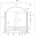
- Fig. 1 is a side view illustrating how a cover 103 of the reactor 100 is detached from a bottom plate 101 of the reactor 100 while a rod-shaped body 10 in accordance with Embodiment 1 of the present invention is inserted in a bottom plate-side hole 102a and in a cover-side hole 104a.
- the cover 103 of the reactor 100 illustrated in Fig. 1 has been slightly lifted above the bottom plate 101.
- the reactor 100 is a device for forming silicon rods 110 by using a Siemens process to deposit polysilicon on silicon core wires placed inside the device.
- the reactor 100 includes the bottom plate 101 and the cover 103.
- the bottom plate 101 is made of metal and is substantially circular.
- the bottom plate 101 has a bottom plate flange 102 which is provided so as to surround the bottom plate 101.
- the bottom plate flange 102 has a plurality of bottom plate-side holes 102a provided in a circumferential direction of the bottom plate 101 at substantially regular intervals.
- the bottom plate-side holes 102a are provided so as to vertically pass through the bottom plate flange 102.
- many electrodes 105 on which silicon core wires are set upright are provided on the bottom plate 101.
- the silicon core wires are each typically formed in a U-shape by two vertical rods and one horizontal bridge rod, and are set upright on the electrodes 105 in an inverted U-shape so as to be perpendicular to the bottom plate 101.
- the silicon rods 110 are formed by depositing polysilicon on the silicon core wires.
- Fig. 1 illustrates only one set of a silicon rod 110 and an electrode 105 for simplification of the drawing.
- the cover 103 is made of metal and has a bell shape.
- the cover 103 has a cover flange 104 which is provided in a lower part of the cover 103 so as to surround the cover 103.
- the cover flange 104 has a plurality of cover-side holes 104a provided in a circumferential direction of the cover 103 at substantially regular intervals.
- the cover-side holes 104a are provided so as to vertically pass through the cover flange 104 and located so as to face the respective bottom plate-side holes 102a.
- bolt holes originally provided in the bottom plate flange 102 and the cover flange 104 can be used as the bottom plate-side holes 102a and the cover-side holes 104a. This makes it unnecessary to carry out any step of additionally providing the bottom plate-side holes 102a in the bottom plate 101 or additionally providing the cover-side holes 104a in the cover 103.
- the reactor 100 can be sealed by (i) bringing the bottom plate 101 into contact with a lower end of the cover 103 so that the bolt holes provided in the bottom plate flange 102 face the respective bolt holes provided in the cover flange 104 and (ii) passing bolts through the bolt holes and tightening the bolts.
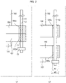
- Fig. 2 is a cross-sectional view that describes a part illustrated in Fig. 1 and enclosed by a chain double-dashed line and that illustrates a state in which the rod-shaped body 10 is inserted in a corresponding bottom plate-side hole 102a and in a corresponding cover-side hole 104a.
- a diagram enclosed by a dotted line L1 illustrates a state in which the cover 103 has not been lifted
- a diagram enclosed by a dotted line L2 illustrates a state in which the cover 103 has been lifted slightly above the bottom plate 101.
- the rod-shaped body 10 (all fall guide) is used to lift the cover 103 so as to detach the cover 103 from the bottom plate 101, together with which the cover 103 forms the reactor 100 in which the silicon rod 110 is contained upright.
- the rod-shaped body 10 includes: a first part 11 to be inserted into the bottom plate-side hole 102a provided in a surrounding area of the bottom plate 101; and a second part 12 to be inserted into the cover-side hole 104a provided in a surrounding area of the cover 103 so as to face the bottom plate-side hole 102a.
- the rod-shaped body 10 includes a nonslip part 13 that is removably provided so as to be closer to a lower end of the rod-shaped body 10 than is the first part 11 and that extends in an axial direction of the rod-shaped body 10 so as to surround the rod-shaped body 10.
- the nonslip part 13 has a length w2 that is measured in a radial direction of the rod-shaped body 10 and is greater than a diameter w1 of the bottom plate-side hole 102a.
- a height h2 from the bottom plate 101 to an upper end of the rod-shaped body 10 as measured in a state in which the rod-shaped body 10 is inserted in the bottom plate-side hole 102a and in the cover-side hole 104a is preferably greater than a height h1 from the bottom plate 101 to an upper end of the silicon rod 110 that stands upright.
- the height h2 is preferably 200 mm to 500 mm greater than the height h1.
- the rod-shaped body 10 is inserted into the bottom plate-side hole 102a provided in the surrounding area of the bottom plate 101 and into the cover-side hole 104a provided in the surrounding area of the cover 103 so as to face the bottom plate-side hole 102a (an inserting step).
- the rod-shaped body 10 is passed through the bottom plate-side hole 102a and the cover-side hole 104a while no nonslip part 13 is fitted to the rod-shaped body 10 at a position that is closer to the lower end of the rod-shaped body 10 than is the first part 11.
- the nonslip part 13 is fitted to the rod-shaped body 10 after the rod-shaped body 10 is passed through the bottom plate-side holes 102a and the cover-side holes 104a.
- the rod-shaped body 10 that has been inserted into the surrounding area of the bottom plate 101 and into the surrounding area of the cover 103 in the inserting step includes two or more rod-shaped bodies 10 that are inserted at respective places at substantially regular intervals in the circumferential direction of the bottom plate 101 and of the cover 103.
- the rod-shaped bodies 10 are inserted in the bottom plate-side holes 102a located at respective both ends of the diameter of the reactor 100 and in the cover-side holes 104a located at respective both ends of the diameter of the reactor 100.
- the cover 103 is lifted upward (in the direction indicated by the arrow in Fig. 1 ) while the rod-shaped bodies 10 are inserted in the bottom plate-side holes 102a and in the cover-side holes 104a (lifting step).
- the cover 103 that is being lifted may laterally swing due to the weight of the silicon rods having fallen against an inner wall of the cover 103.
- a lateral swing of the cover 103 causes, for example, (1) a problem such that the cover 103 hits the silicon rod 110 that stands upright in the reactor 100, and the silicon rod 110 falls over accordingly, or (2) a problem such that the cover 103 hits a protective wall provided around the reactor 100, so that the cover 103 can no longer be lifted.
- the cover 103 is lifted along the rod-shaped bodies 10 by being lifted while the rod-shaped bodies 10 are inserted in the bottom plate-side holes 102a and in the cover-side holes 104a. This makes it possible to substantially vertically lift the cover 103. Consequently, even in a case where the silicon rod 110 is in contact with an inner wall of the reactor 100, the cover 103 can be prevented from laterally swinging while being lifted, and can be lifted to a position higher than an upper end of the silicon rod 110 that stands upright on the bottom plate 101.
- a method for manufacturing the silicon rod 110 includes the inserting step and the lifting step as the step of detaching the cover 103 which forms the reactor 100 together with the bottom plate 101, it is possible to achieve a method for manufacturing the silicon rod 110, the method bringing about the following effect. Specifically, it is possible to achieve a method for manufacturing the silicon rod 110, the method making it possible to, even in a case where the silicon rod 110 is in contact with the inner wall of the reactor 100, open the reactor 100 by lifting the cover 103.
- the inventor has conducted various analyses of a rod-shaped body 10 and found that the lateral swing of the cover 103 which is being lifted can be optimally prevented by designing the rod-shaped body 10 on the basis of the following description.
- the rod-shaped body 10 desirably has a diameter that is 85% to 98%, preferably 90% to 95%, and particularly preferably 92% to 94% of the diameter of a bottom plate-side hole 102a and a cover-side hole 104a.
- a ratio of the diameter of the rod-shaped body 10 to the diameter of the bottom plate-side hole 102a and the cover-side hole 104a is too large, the rod-shaped body 10 gets stuck in the bottom plate-side hole 102a and in the cover-side hole 104a. This makes it impossible to smoothly pass the rod-shaped body 10 through the bottom plate-side hole 102a and the cover-side hole 104a, and further makes it impossible to smoothly lift the cover 103.
- the cover 103 swings laterally in a range equal to or greater than an allowable range and, moreover, the rod-shaped body 10 decreases in strength.
- the rod-shaped body 10 can have a diameter that is not limited to the above diameter and is not limited to any particular dimeter, provided that a lower surface of the cover flange 104 laterally swings in a range of -100 mm to +100 mm, preferably -70 mm to +70 mm, and particularly preferably -40 mm to +40 mm, relative to an upper surface of the bottom plate flange 102.
- a lower surface of the cover flange 104 laterally swings in a range of -100 mm to +100 mm, preferably -70 mm to +70 mm, and particularly preferably -40 mm to +40 mm, relative to an upper surface of the bottom plate flange 102.
- a silicon rod 110 into which a silicon core wire standing on a circumference of one of the concentric circles which one is the closest to the cover 103 has grown so as to have a diameter of 100 mm to 200 mm is at a distance of typically approximately several hundred millimeters from the inner wall of the cover 103.
- the cover 103 is required to laterally swing in the range of -100 mm to +100 mm so that the cover 103 will not come into contact with the silicon rod 110.
- the rod-shaped body 10 desirably has a diameter of 10 mm to 50 mm, preferably 15 mm to 45 mm, and particularly preferably 20 mm to 40 mm.
- the rod-shaped body 10 that has a diameter of less than 10 mm greatly bends, so that the cover 103 laterally swings more widely while being lifted.
- the rod-shaped body 10 that has a diameter of more than 50 mm becomes heavier. This results in lower workability.
- the rod-shaped body 10 can have a length that is not limited to any particular length, provided that the length makes it possible to lift the cover 103 to a position higher than the upper end of the silicon rod 110 that has grown in the reactor 100.
- the height h2 from the bottom plate 101 to the upper end of the rod-shaped body 10 is preferably 200 mm to 500 mm greater than the height h1 from the bottom plate 101 to the upper end of the silicon rod 110 that stands upright from the bottom plate 101.
- the rod-shaped body 10 typically has a length of 500 mm to 3000 mm.
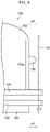
- Fig. 3 is a side view illustrating the reactor 100 having a projection 106.
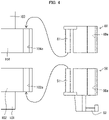
- Fig. 4 is a cross-sectional view describing Variation 1 of the present invention and schematically illustrating configurations of jigs 50 and 60 of the rod-shaped body 10.
- the cover 103 of the reactor 100 can have various shapes.
- the cover 103 may have the projection 106 provided on a side-wall surface 103a (an outer wall) of the cover 103 (see Fig. 3 ).
- the projection 106 serves as, for example, a projecting structure such as a nozzle and an inspection manhole.
- the distance w3 is a distance from an outer edge of the bottom plate 101 to the bottom plate-side hole 102a, and is also a distance from the outer wall of the cover 103 to the cover-side hole 104a.
- the distance w4 is a distance from the outer wall of the cover 103 to an end of the projection 106 provided on the outer wall of the cover 103, the end facing away from the outer wall of the cover 103.
- the rod-shaped body 10 bumps against the projection 106 depending on where the projection 106 is provided. In that case, it is impossible to insert the rod-shaped body 10 into the bottom plate-side hole 102a and into the cover-side hole 104a. This makes it impossible to vertically lift the cover 103. For this reason, the jigs 50 and 60 are used in a case where the projection 106 is provided on the cover 103 and the distance w3 is shorter than the distance w4.
- the jig 50 in order to provide, in the surrounding area of the bottom plate 101, the bottom plate-side hole 102a into which the rod-shaped body 10 is to be inserted, the jig 50 includes an attachment part 51 to be attached in the surrounding area of the bottom plate 101, and has a hole 50a formed therein that serves as the bottom plate-side hole 102a.
- the jig 50 also includes a supporting part 52, provided in a lower part of the jig 50, for supporting a lower end part of the rod-shaped body 10.
- the jig 50 is fitted to the bottom plate flange 102 by inserting, from below, the attachment part 51 into the bottom plate-side hole 102a formed in the bottom plate flange 102, and the first part 11 of the rod-shaped body 10 is inserted in the hole 50a serving as the bottom plate-side hole 102a.
- the jig 60 includes an attachment part 61 to be attached in the surrounding area of the cover 103, and has a hole 60a formed therein that serves as the cover-side hole 104a.
- the jig 60 is fitted to the cover flange 104 by inserting, from above, the attachment part 61 into the cover-side hole 104a formed in the cover flange 104, and the second part 12 of the rod-shaped body 10 is inserted into the hole 60a serving as the cover-side hole 104a.
- Fig. 5 illustrates an example of how the jig 60 has been fitted.
- Fig. 5 is a partial top view of the reactor 100 and illustrates a state in which the jig 60 has been fitted to the cover flange 104 of the reactor 100.
- a distance from the outer edge of the bottom plate 101 to the hole 50a serving as the bottom plate-side hole 102a and a distance from the outer wall of the cover 103 to the hole 60a serving as the cover-side hole 104a are each longer than a distance from the outer wall of the cover 103 to an end of the projection 106 provided on the outer wall of the cover 103, the end facing away from the outer wall of the cover 103.
- the rod-shaped body 10 can be disposed so as not to bump against the projection 106 and so as to be substantially parallel to the side-wall surface 103a of the cover 103 and substantially vertically extend. This makes it possible to lift the cover 103 above the upper end of the silicon rod 110.
- a ratio of the diameter of the rod-shaped body 10 to the diameter of the hole 50a serving as the bottom plate-side hole 102a and the hole 60a serving as the cover-side hole 104a is designed so as to be similar to a ratio of the diameter of the rod-shaped body 10 to the diameter of the bottom plate-side hole 102a and the cover-side hole 104a.
- Fig. 6 is a cross-sectional view describing Variation 2 of an embodiment of the present invention and illustrating a state in which a rod-shaped body 10A, which is a variation of the rod-shaped body 10, is inserted in the bottom plate-side hole 102a and in the cover-side hole 104a.
- the rod-shaped body 10 In the step of lifting the cover 103, it is possible to use the rod-shaped body 10 whose length and thickness are changed depending on a lifted state of the cover 103. Specifically, it is possible to prepare a shorter rod-shaped body (the rod-shaped body 10A) having a shorter length than a longer rod-shaped body (the rod-shaped body 10) that has been described with reference to Fig. 1 and designed such that the height h2 from the bottom plate 101 to the upper end of the rod-shaped body 10 is greater than the height h1 from the bottom plate 101 to the upper end of the silicon rod 110 standing upright.
- One of the shorter and longer rod-shaped bodies can be selectively used, or both the shorter and longer rod-shaped bodies can be simultaneously used.
- the bottom plate 101 and the cover 103 are more likely to be positionally displaced from each other in the reactor 100.
- the bottom plate flange 102 and the cover flange 104 may partially strongly adhere to each other during the detachment of the cover 103 from the bottom plate 101. In such a case, it may be necessary to apply a heavy load in order to separate the cover flange 104 from the bottom plate flange 102.
- a load caused by the swing is particularly high.
- the rod-shaped body 10A is desirably thick and short. Specifically, the rod-shaped body 10A has a length of, for example, 300 mm to 400 mm.
- the rod-shaped body 10A desirably has a diameter in a range of 92% to 97%, which is the particularly preferable range among the above-described ranges of the diameter relative to the diameter of the bottom plate-side hole 102a and the cover-side hole 104a.
- the diameter of the rod-shaped body 10A is desirably 20 mm to 30 mm in actual size.
- the rod-shaped body 10A is provided with a handle 10A1 which is closer to an upper end of the rod-shaped body 10A than is the second part 12 and which extends in an axial direction of the rod-shaped body 10A so as to surround the rod-shaped body 10A (see Fig. 6 ).
- the rod-shaped body 10A is used to increase the positional stability during the period from the detachment of the bolts to the beginning of the lifting of the cover 103. This eliminates the need to necessarily provide the nonslip part 13, which is provided so as to be closer to the lower end of the rod-shaped body 10 than is the first part 11. Further, in order to carry out an operation while the cover 103 is being lifted approximately one meter, it is possible to use a longer rod-shaped body (not illustrated) than the rod-shaped body 10A.
- Fig. 7 is a side view illustrating how the cover 103 of the reactor 100 is detached from the bottom plate 101 of the reactor 100 while the protective structure 200 in accordance with an embodiment of the present invention is provided around the reactor 100.
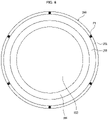
- Fig. 8 is a top view of the protective structure 200.
- Fig. 9 is a view for describing the protective structure 200, the view schematically illustrating a state in which the cover 103 has been detached from the reactor 100 illustrated in Fig. 7 .
- Fig. 10 is a view for describing the protective structure 200, the view schematically illustrating a state in which a takeout window 207 of the protective structure 200 is open in Fig. 9 .
- Fig. 10 is a view for describing the protective structure 200, the view schematically illustrating a state in which a takeout window 207 of the protective structure 200 is open in Fig. 9 .
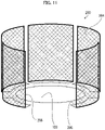
- FIG. 11 is a view for describing the protective structure 200, the view illustrating a state in which the protective structure 200 has been divided.
- Figs. 9 to 11 do not illustrate components of the protective structure 200 which are different from a protective wall surface 204, a protective plate 205, dividing lines 206, and the takeout window 207.
- the protective structure 200 is a structure for preventing, during the detachment of the cover 103 from the bottom plate 101, silicon rods 110 standing upright on the bottom plate 101 from falling over outside the bottom plate 101 and being scattered over a floor.
- the protective structure 200 is provided around the reactor 100. It is possible to provide the protective structure 200 around the reactor 100 in order to only lift the cover 103 against which the silicon rods 110 have fallen.
- the protective structure 200 includes a first frame body 201 (frame body), a second frame body 202, a plurality of third frame bodies 203, and a protective wall surface 204 (see Figs. 7 and 8 ).
- the first frame body 201 is shaped so as to surround the bottom plate 101 of the reactor 100 in which the silicon rods 110 are contained.
- the first frame body 201 is connected to the plurality of third frame bodies 203 extending vertically.
- the first frame body 201 is supported by the plurality of third frame bodies 203 at a position at which the first frame body 201 surrounds the bottom plate 101.
- the second frame body 202 extends horizontally and is connected to upper ends of the plurality of third frame bodies 203.
- the second frame body 202 is supported by the plurality of third frame bodies 203 so as to extend horizontally.
- Each of the plurality of third frame bodies 203 is connected to the first frame body 201 and the second frame body 202, and supports the first frame body 201 and the second frame body 202.
- the protective wall surface 204 extends vertically upward from the first frame body 201 and forms a storage space 210 for the silicon rods 110.
- the protective wall surface 204 has a mesh structure.
- the protective structure 200 includes the protective plate 205 having a ring shape and provided between the first frame body 201 and the bottom plate 101 of the reactor 100.
- the protective plate 205 has a flat surface that extends so as to surround the bottom plate 101 and that spreads horizontally.
- the protective plate 205 is provided, for example, so as to be level with a lower surface of the bottom plate flange 102 of the reactor 100. Since the protective plate 205 is thus provided between the bottom plate 101 and the first frame body 201, the silicon rod 110 that has fallen over are scattered on the protective plate 205. This allows the protective structure 200 for the silicon rods 110 to, even in a case where the cover 103 of the reactor 100 has been detached, prevent the silicon rod 110 from being scattering over the floor (see Fig. 9 ).
- the protective wall surface 204 includes a takeout window 207 formed therein for taking out the silicon rods 110 that are contained in the reactor 100.
- the takeout window 207 is formed by being surrounded by two fourth frame bodies 208 and two fifth frame bodies 209.
- the fourth frame bodies 208 extend vertically and are provided between the first frame body 201 and the second frame body 202.
- the fifth frame bodies 209 extend horizontally and are provided between the two fourth frame bodies 208.
- the protective structure 200 can be divided along dividing lines 206 each extending vertically upward from a corresponding one of a plurality of points P1 on the first frame body 201. That is, the protective structure 200 as illustrated in Fig. 8 can be divided into six parts (see Fig. 11 ). This makes it possible to efficiently assemble the protective structure 200 by, for example, dividing the protective structure 200 for the silicon rods 110 into parts having sizes suitable for transportation and storage of the silicon rods 110.
- the above configuration allows the protective wall surface 204 to have a mesh structure in the protective structure 200 for the silicon rods 110, the protective wall surface 204 extending vertically upward from the first frame body 201 and forming the storage space for the silicon rods 110.
- the protective structure 200 for the silicon rods 110 it is possible to achieve visibility from outside to inside the protective structure 200 while preventing the silicon rods 110 from being scattered outside the protective structure 200 for the silicon rods 110.
- the protective structure 200 for the silicon rods 110 makes it possible to, for example, while checking how the silicon rods 110 have fallen over, carry out an operation to lift the cover 103 of the reactor 100.
- the silicon rods 110 are easily broken even by a small impact. Due to an impact caused when the silicon rods 110 begin to fall toward the outside of the reactor 100 during the lifting of the cover 103 or an impact caused when the silicon rods fall over, the silicon rod 110 are broken into pieces of silicon in massive or powdery form that are widely distributed in terms of size. Almost all of these pieces of silicon need to be captured.
- the inventor has conducted various analyses and found that by lifting the cover 103 while the protective structure 200 that meets design requirements described below is provided around the reactor 100, it is possible to cause the protective structure 200 to receive (i) the silicon rods 110 having fallen over and (ii) pieces into which the silicon rods 110 have been broken.
- the silicon rods 110 that have grown typically have a U-shape and have a length of four meters to six meters in terms of a linear length and have a thickness of 100 mm to 200 mm. Assuming that the specific gravity of silicon is 2.4 g/cm 3 , a single silicon rod 110 has a weight of 75 kg to 460 kg, and the silicon rods 110 have a total weight of 1300 kg to 8200 kg in the reactor 100 for 18 U-shaped rods.
- the protective structure 200 that does not have a sufficient strength may cause the silicon rods 110 and fragments produced when the silicon rods 110 are broken to crash through the protective structure 200 and may harm a worker who carries out an operation to open the reactor.
- each of the silicon rods 110 (1) slowly falls toward the outside of the reactor 100 from joints between a silicon rod 110 and corresponding electrodes 105, (2) slowly leans against the protective structure 200 and remains in a rod form or is broken up due to an impact caused by its falling against the protective structure 200, and (3) is divided into silicon blocks and/or silicon pieces and is scattered inside the protective structure 200.
- a static pressure applied on a point A (not illustrated) in an inner surface of the protective pressure 200 when all the silicon rods 110 on the reactor 100 lean against the protective structure 200 depends on a distance L between the bottom plate flange 102 and the protective structure 200 and a weight W of all of the silicon rods 110 inside the reactor 100. That is, the magnitude of the static pressure can be estimated by setting respective values of the distance L and the weight W. For example, in a case where the protective wall surface 204 of the protective structure 200 is placed within 1 m from an outer diameter of the bottom plate flange 102 of the reactor 100, the static pressure that is applied to the protective wall surface 204 of the protective structure 200 is lower than or equal to half the total weight of the silicon rods 110.
- the protective wall surface 204 is preferably made of metal and preferably has a mesh structure. This is because the protective wall surface 204 that is lighter further facilitates an operation to place the protective wall surface 204.
- the protective wall surface 204 that has a too small mesh size causes the inside of the protective structure 200 to be less visible from the outside of the protective structure 200.
- the protective wall surface 204 desirably has an optimal mesh size of 2 mesh to 10 mesh, preferably 3 mesh to 7 mesh, and particularly preferably 3 mesh to 5 mesh.
- the wire gauze of the protective wall surface 204 desirably has 16 gauge to 20 gauge, preferably 17 gauge to 19 gauge, and particularly preferably 18 gauge. This configuration makes it possible to accept the static pressure caused by the fall of the silicon rods 110.
- the protective structure 200 that is structured to be divided makes even lighter individual parts into which the protective structure 200 is divided and facilitates an operation to place the protective structure 200.
- the number of parts into which the protective structure 200 is divided is desirably selected on the basis of weights that allow manual transportation. Specifically, the number of the parts into which the protective structure 200 is divided is desirably determined such that each of the parts into which the protective structure 200 is divided has a weight of 80 kg to 180 kg, preferably 100 kg to 160 kg, and particularly preferably 120 kg to 150 kg.
- the following description will discuss an example of assembly of the protective structure 200 that is structured to be divided.
- the parts into which the protective structure 200 is divided are placed in close contact with each other so as to surround the reactor 100 in the form of a ring. Then, joints of adjacent ones of the parts into which the protective structure 200 is divided are fixed by quick coupling so that the protective structure 200 into which the parts are integrated is assembled.
- the first frame body 201 of the protective structure 200 forms a circle which can have any diameter provided that the diameter is larger than the outer diameter of the bottom plate flange 102 and the cover flange 104 of the reactor 100.
- the circle formed by the first frame body 201 desirably has a diameter that is 0 mm to 1000 mm, preferably by 200 mm to 700 mm, and particularly preferably by 300 mm to 600 mm larger than the outer diameter of the bottom plate flange 102 and the cover flange 104. This makes it possible to smoothly lift the cover 103 inside the protective structure 200 and to allow a lower static pressure to be applied to the protective wall surface 204 by the silicon rods 110 having fallen against the protective wall surface 204.
- the silicon rods 110 that have been broken up due to an impact of their falling against the protective structure 200 are divided into silicon blocks and/or silicon pieces, and are scattered inside the protective structure 200.
- the inventor has found that some silicon blocks and/or silicon pieces jump over the protective structure 200 depending on the particle diameter of the silicon pieces produced or the height of the protective structure 200.
- the inventor measured a size distribution of silicon blocks and/or silicon pieces each produced due to an impact of collapse of the silicon rods 110. Results of the measurement have turned out that silicon pieces which are produced in a case where the silicon rods 110 having a length of several meters and having a diameter of 100 mm to 200 mm are collapsed and broken have a minimum size of not less than approximately 10 mm.
- the protective structure 200 can have any height provided that the height is greater than a height H (not illustrated) from a floor of a reactor chamber in which the reactor 100 is placed to upper ends of the silicon rods 110 that stand upright on the bottom plate 101 without being collapsed.
- the protective structure 200 that has a height much greater than the height H is not preferable. This is because the protective structure 200 thus configured makes it necessary to lift the silicon rods 110 too high in order to take out the silicon rods 110 inside the protective structure 200 by moving the silicon rods 110 above the protective structure 200. This makes workability worse.
- the protective structure 200 that has a height much smaller than the height H makes it impossible to, when the silicon rods 110 fall over toward the outside the reactor 100, prevent silicon pieces that are produced due to collapse of the silicon rods 110 from jumping over the protective structure 200.
- the protective structure 200 therefore desirably has a height that is -200 mm to 800 mm, preferably 0 mm to 500 mm, and particularly preferably 0 mm to 200 mm greater than the height H.
- the distribution of silicon pieces produced due to the breakup of the silicon rods 110 was evaluated as below.
- the silicon rods 110 that were not collapsed in the reactor and then successfully taken out of the reactor 100 were set upright on a flat floor. These silicon rods 110 were caused to fall from lower ends of the silicon rods 110. Silicon pieces produced due to such collapse of the silicon rods 110 as described above were subjected to a measurement of the weight distribution of sizes thereof. In order that the silicon rods 110 having fallen over would not directly contact a surface of the floor, other silicon rods 110 different from the silicon rods 110 to be caused to fall on the flat floor were caused to lie sideway and densely placed so as to surround the silicon rods 110 to be caused to fall.
- the following description will discuss an example of a method for manufacturing a silicon rod with use of the protective structure 200.
- the bottom plate flange 102 and the cover flange 104 of the reactor 100 are unbolted after deposition of the silicon rods 110 is ended.
- the rod-shaped body 10 is inserted into the bottom plate-side hole 102a provided in the surrounding area of the bottom plate 101 and into the cover-side hole 104a provided in the surrounding area of the cover 103 so as to face the bottom plate-side hole 102a.
- the protective structure 200 is provided around the reactor 100 so that the storage space 210 for the silicon rods 110 is formed.
- the protective structure 200 includes the first frame body 201 that is shaped so as to surround the bottom plate 101 and the protective wall surface 204 that extends vertically upward from the first frame body 201 and that has a mesh structure. Subsequently, the cover 103 is lifted upward while the rod-shaped body 10 is inserted in the bottom plate-side hole 102a and in the cover-side hole 104a.
- a protective structure for a silicon rod in accordance with an aspect of the present invention includes a frame body that is shaped so as to surround a bottom plate of a reactor in which a silicon rod is contained; and a protective wall surface that extends vertically upward from the frame body and that forms a storage space for the silicon rod, the protective wall surface having a mesh structure.
- the protective structure for a silicon rod includes a protective wall surface that has a mesh structure, the protective wall surface extending vertically upward from the frame body and forming a storage space for the silicon rods.
- the protective structure for the silicon rods therefore makes it possible to achieve visibility from outside to inside the protective structure while preventing the silicon rods from being scattered outside the protective structure for the silicon rods.
- the protective structure for the silicon rods makes it possible to, for example, while checking how the silicon rods have fallen over, lift a cover of the reactor.
- the protective structure for a silicon rod can include a protective plate which is provided between the frame body and the bottom plate of the reactor, and which has a flat surface that extends so as to surround the bottom plate and that spreads horizontally.
- the protective structure for the silicon rods makes it possible to prevent the silicon rods from being scattered on the floor.
- the protective wall surface can be capable of being divided along dividing lines extending vertically upward from respective points on the frame body.
- This configuration makes it possible to divide the protective structure for the silicon rods along the dividing lines. This makes it possible to provide the protective structure for the silicon rods, the protective structure that can be efficiently assembled by, for example, dividing the protective structure for the silicon rods into parts having sizes suitable for transportation and storage of the silicon rods.
- the protective wall surface can include a takeout window formed therein for taking out the silicon rod that is contained in the reactor.
- This configuration makes it possible to take out the silicon rods through the takeout window while the protective structure for the silicon rods is provided without being disassembled.
- a method for manufacturing a silicon rod includes a detaching step of detaching a cover from a bottom plate, together with which the cover forms a reactor in which the silicon rod is contained, the detaching step being carried out after a storage space of the silicon rod is formed by placing a protective structure including: a frame body that is shaped so as to surround the bottom plate; and a protective wall surface that extends vertically upward from the frame body and that has a mesh structure.
- the detaching step in the method for manufacturing a silicon rod is carried out after a protective structure is placed so that a storage space for the silicon rods is formed, the protective structure including a frame body that is shaped so as to surround the bottom plate and a protective wall surface that extends vertically upward from the frame body and that has a mesh structure.
- the protective structure including a frame body that is shaped so as to surround the bottom plate and a protective wall surface that extends vertically upward from the frame body and that has a mesh structure.
- the present invention is not limited to the embodiments above, but can be altered in various ways by a skilled person within the scope of the claims.
- the present invention encompasses, in its technical scope, any embodiment derived by combining technical means disclosed in differing embodiments.
Landscapes
- Chemical & Material Sciences (AREA)
- Organic Chemistry (AREA)
- Inorganic Chemistry (AREA)
- Engineering & Computer Science (AREA)
- Crystallography & Structural Chemistry (AREA)
- Materials Engineering (AREA)
- Metallurgy (AREA)
- Silicon Compounds (AREA)
Abstract
Description
- The present invention relates to a protective structure that is used during the manufacture of a silicon rod, and to a method for manufacturing a silicon rod.
- High-purity polysilicon is useful as a raw material for manufacturing single-crystal silicon for semiconductors by the Czochralski method (CZ method) or the floating zone method (FZ method). High-purity polysilicon is also useful as a raw material for manufacturing polycrystalline silicon for solar cells by a casting method to which a unidirectional solidification method is applied.
- Polysilicon is typically manufactured by a Siemens process. In the Siemens process, a silicon-containing gas and hydrogen are put into a reactor, and the silicon-containing gas and the hydrogen that have been put into the reactor react with each other on a silicon core wire which is heated by the passage of electric current therethrough in the reactor, so that polysilicon is deposited on the silicon core wire. As the silicon-containing gas, monosilane (SiH4) or trichlorosilane (SiHCl3) is used.
- The most common reactor is composed of a bell-shaped shell and a bottom plate which are made of metal and are capable of being cooled. The bottom plate is provided with many electrodes on which silicon core wires are set upright, an inlet through which a source material gas is to be introduced, and an outlet through which a gas inside the reactor is to be discharged.
- The silicon core wires are each typically formed in a U-shape by two vertical rods and one horizontal bridge rod and are set upright in an inverted U-shape so as to be perpendicular to the electrodes provided on the bottom plate of the reactor. Polysilicon that is deposited on the silicon core wire grows with time in a direction in which the diameter of the silicon core wire extends. The reaction is ended when the diameter of the deposited polysilicon reaches a predetermined diameter. Silicon rods (polysilicon) which have stopped growing are cooled down typically to room temperature. Inverted U-shaped silicon rods thus obtained have a height of several meters and each have a weight of several tens of kilograms.
- The silicon rods are taken out of the reactor after being cooled to room temperature. Since the Siemens process is not a continuous process but a batch process, it is necessary to temporarily shut down the reactor upon the end of the deposition, open the reactor, and take the obtained silicon rod out of the reactor. The reactor is opened typically by slowly lifting upward a cover of the reactor that is bell-shaped. The silicon rods are taken out of the reactor such that the inverted U-shaped silicon rods are lifted one by one and moved to the outside of the reactor. The silicon rods are loaded on, for example, a carrier and transferred.
- For example,
WO2015/039841 discloses a protective wall-related technique that is used to take a silicon rod out of a reactor.WO2015/039841 discloses a technique in which a non-air-permeable protective wall is provided around the reactor so that the surface of the silicon rod is prevented from being contaminated with outside air during opening of the reactor. - However, an object of such a conventional technique as described above is to prevent contamination of a silicon rod, and therefore has the following problem. Specifically, according to the conventional technique, which fails to consider visibility from outside to inside of a protective wall, it is impossible to open a reactor while checking, from the outside of the protective wall, a falling over state of a silicon rod located inside the reactor.
- The present invention has been made in light of the above-described conventional problem. An object of the present invention is to provide a protective structure which makes it possible to, while checking a falling over state of a silicon rod, carry out an operation to open a reactor.
- In order to solve the above problem, a protective structure for a silicon rod in accordance with an aspect of the present invention includes a frame body that is shaped so as to surround a bottom plate of a reactor in which a silicon rod is contained; and a protective wall surface that extends vertically upward from the frame body and that forms a storage space for the silicon rod, the protective wall surface having a mesh structure.
- A method for manufacturing a silicon rod, in accordance with an aspect of the present invention, includes a detaching step of detaching a cover from a bottom plate, together with which the cover forms a reactor in which the silicon rod is contained, the detaching step being carried out after a storage space of the silicon rod is formed by placing a protective structure including: a frame body that is shaped so as to surround the bottom plate and a protective wall surface that extends vertically upward from the frame body and that has a mesh structure.
- An aspect of the present invention makes it possible to, while checking a falling over state of a silicon rod, carry out an operation to open a reactor.
-
- Fig. 1
- is a side view illustrating how a cover of a reactor is detached from a bottom plate of the reactor while a rod-shaped body in accordance with an embodiment of the present invention is inserted in a bottom plate-side hole and in a cover-side hole.
- Fig. 2
- is a cross-sectional view illustrating a state in which the rod-shaped body is inserted in the bottom plate-side hole and in the cover-side hole.
- Fig. 3
- is a side view illustrating the reactor having a projection.
- Fig. 4
- is a cross-sectional
view describing Variation 1 of the embodiment of the present invention and schematically illustrating configurations of jigs of the rod-shaped body. - Fig. 5
- is a partial top view of the reactor illustrating a state in which the jig has been fitted to the cover of the reactor.
- Fig. 6
- is a cross-sectional view describing Variation 2 of an embodiment of the present invention and illustrating a variation of the rod-shaped body.
- Fig. 7
- is a side view illustrating how the cover of the reactor is detached from the bottom plate of the reactor while a protective structure in accordance with an embodiment of the present invention is provided around the reactor.
- Fig. 8
- is a top view of the protective structure.
- Fig. 9
- is a view for describing the protective structure, the view schematically illustrating a state in which the cover has been detached from the reactor illustrated in
Fig. 7 . - Fig. 10
- is a view for describing the protective structure, the view schematically illustrating a state in which a takeout window is open in
Fig. 9 . - Fig. 11
- is a view for describing the protective structure, the view illustrating a state in which the protective structure has been divided.
- The following description will specifically discuss an embodiment of the present invention. For convenience of description, members having functions identical to those of the respective members described in variations of the embodiment are given respective reference signs, and a description of those members is omitted as appropriate. For convenience, the embodiment refers to a vertical direction assuming that a
cover 103 side of areactor 100 is an upper side and abottom plate 101 side of thereactor 100 is a lower side. Note that the following description will refer to the vertical direction merely for convenience of description, and the present invention can be carried out in a direction that is not limited to the vertical direction. - The following description will schematically discuss a configuration of the
reactor 100 with reference toFig. 1. Fig. 1 is a side view illustrating how acover 103 of thereactor 100 is detached from abottom plate 101 of thereactor 100 while a rod-shaped body 10 in accordance withEmbodiment 1 of the present invention is inserted in a bottom plate-side hole 102a and in a cover-side hole 104a. Thecover 103 of thereactor 100 illustrated inFig. 1 has been slightly lifted above thebottom plate 101. - The
reactor 100 is a device for formingsilicon rods 110 by using a Siemens process to deposit polysilicon on silicon core wires placed inside the device. Thereactor 100 includes thebottom plate 101 and thecover 103. - The
bottom plate 101 is made of metal and is substantially circular. Thebottom plate 101 has abottom plate flange 102 which is provided so as to surround thebottom plate 101. Thebottom plate flange 102 has a plurality of bottom plate-side holes 102a provided in a circumferential direction of thebottom plate 101 at substantially regular intervals. The bottom plate-side holes 102a are provided so as to vertically pass through thebottom plate flange 102. Further,many electrodes 105 on which silicon core wires are set upright are provided on thebottom plate 101. The silicon core wires are each typically formed in a U-shape by two vertical rods and one horizontal bridge rod, and are set upright on theelectrodes 105 in an inverted U-shape so as to be perpendicular to thebottom plate 101. As described earlier, thesilicon rods 110 are formed by depositing polysilicon on the silicon core wires.Fig. 1 illustrates only one set of asilicon rod 110 and anelectrode 105 for simplification of the drawing. - The
cover 103 is made of metal and has a bell shape. Thecover 103 has acover flange 104 which is provided in a lower part of thecover 103 so as to surround thecover 103. Thecover flange 104 has a plurality of cover-side holes 104a provided in a circumferential direction of thecover 103 at substantially regular intervals. The cover-side holes 104a are provided so as to vertically pass through thecover flange 104 and located so as to face the respective bottom plate-side holes 102a. - Note that bolt holes originally provided in the
bottom plate flange 102 and thecover flange 104 can be used as the bottom plate-side holes 102a and the cover-side holes 104a. This makes it unnecessary to carry out any step of additionally providing the bottom plate-side holes 102a in thebottom plate 101 or additionally providing the cover-side holes 104a in thecover 103. Thereactor 100 can be sealed by (i) bringing thebottom plate 101 into contact with a lower end of thecover 103 so that the bolt holes provided in thebottom plate flange 102 face the respective bolt holes provided in thecover flange 104 and (ii) passing bolts through the bolt holes and tightening the bolts. - The following description will discuss the rod-shaped
body 10 with reference toFigs. 1 and2. Fig. 2 is a cross-sectional view that describes a part illustrated inFig. 1 and enclosed by a chain double-dashed line and that illustrates a state in which the rod-shapedbody 10 is inserted in a corresponding bottom plate-side hole 102a and in a corresponding cover-side hole 104a. InFig. 2 , a diagram enclosed by a dotted line L1 illustrates a state in which thecover 103 has not been lifted, and a diagram enclosed by a dotted line L2 illustrates a state in which thecover 103 has been lifted slightly above thebottom plate 101. The rod-shaped body 10 (all fall guide) is used to lift thecover 103 so as to detach thecover 103 from thebottom plate 101, together with which thecover 103 forms thereactor 100 in which thesilicon rod 110 is contained upright. - As illustrated in L1 of
Fig. 2 , the rod-shapedbody 10 includes: afirst part 11 to be inserted into the bottom plate-side hole 102a provided in a surrounding area of thebottom plate 101; and asecond part 12 to be inserted into the cover-side hole 104a provided in a surrounding area of thecover 103 so as to face the bottom plate-side hole 102a. The rod-shapedbody 10 includes anonslip part 13 that is removably provided so as to be closer to a lower end of the rod-shapedbody 10 than is thefirst part 11 and that extends in an axial direction of the rod-shapedbody 10 so as to surround the rod-shapedbody 10. As illustrated in L2 ofFig. 2 , thenonslip part 13 has a length w2 that is measured in a radial direction of the rod-shapedbody 10 and is greater than a diameter w1 of the bottom plate-side hole 102a. - In addition, as illustrated in
Fig. 1 , a height h2 from thebottom plate 101 to an upper end of the rod-shapedbody 10 as measured in a state in which the rod-shapedbody 10 is inserted in the bottom plate-side hole 102a and in the cover-side hole 104a is preferably greater than a height h1 from thebottom plate 101 to an upper end of thesilicon rod 110 that stands upright. In particular, the height h2 is preferably 200 mm to 500 mm greater than the height h1. - The following description will discuss an example of a method for detaching the
cover 103 from thebottom plate 101, together with which thecover 103 forms thereactor 100 in which thesilicon rod 110 is contained upright. - First, the rod-shaped
body 10 is inserted into the bottom plate-side hole 102a provided in the surrounding area of thebottom plate 101 and into the cover-side hole 104a provided in the surrounding area of thecover 103 so as to face the bottom plate-side hole 102a (an inserting step). In this inserting step, the rod-shapedbody 10 is passed through the bottom plate-side hole 102a and the cover-side hole 104a while nononslip part 13 is fitted to the rod-shapedbody 10 at a position that is closer to the lower end of the rod-shapedbody 10 than is thefirst part 11. Thenonslip part 13 is fitted to the rod-shapedbody 10 after the rod-shapedbody 10 is passed through the bottom plate-side holes 102a and the cover-side holes 104a. Further, the rod-shapedbody 10 that has been inserted into the surrounding area of thebottom plate 101 and into the surrounding area of thecover 103 in the inserting step includes two or more rod-shapedbodies 10 that are inserted at respective places at substantially regular intervals in the circumferential direction of thebottom plate 101 and of thecover 103. Typically six, preferably three, and particularly preferably two rod-shapedbodies 10 are to be inserted. For example, in a case where two rod-shapedbodies 10 are inserted, the rod-shapedbodies 10 are inserted in the bottom plate-side holes 102a located at respective both ends of the diameter of thereactor 100 and in the cover-side holes 104a located at respective both ends of the diameter of thereactor 100. - Next, the
cover 103 is lifted upward (in the direction indicated by the arrow inFig. 1 ) while the rod-shapedbodies 10 are inserted in the bottom plate-side holes 102a and in the cover-side holes 104a (lifting step). - The
cover 103 that is being lifted unfortunately may laterally swing due to the weight of the silicon rods having fallen against an inner wall of thecover 103. Specifically, such a lateral swing of thecover 103 causes, for example, (1) a problem such that thecover 103 hits thesilicon rod 110 that stands upright in thereactor 100, and thesilicon rod 110 falls over accordingly, or (2) a problem such that thecover 103 hits a protective wall provided around thereactor 100, so that thecover 103 can no longer be lifted. - However, the
cover 103 is lifted along the rod-shapedbodies 10 by being lifted while the rod-shapedbodies 10 are inserted in the bottom plate-side holes 102a and in the cover-side holes 104a. This makes it possible to substantially vertically lift thecover 103. Consequently, even in a case where thesilicon rod 110 is in contact with an inner wall of thereactor 100, thecover 103 can be prevented from laterally swinging while being lifted, and can be lifted to a position higher than an upper end of thesilicon rod 110 that stands upright on thebottom plate 101. - In a case where a method for manufacturing the
silicon rod 110 includes the inserting step and the lifting step as the step of detaching thecover 103 which forms thereactor 100 together with thebottom plate 101, it is possible to achieve a method for manufacturing thesilicon rod 110, the method bringing about the following effect. Specifically, it is possible to achieve a method for manufacturing thesilicon rod 110, the method making it possible to, even in a case where thesilicon rod 110 is in contact with the inner wall of thereactor 100, open thereactor 100 by lifting thecover 103. - The inventor has conducted various analyses of a rod-shaped
body 10 and found that the lateral swing of thecover 103 which is being lifted can be optimally prevented by designing the rod-shapedbody 10 on the basis of the following description. - Specifically, the rod-shaped
body 10 desirably has a diameter that is 85% to 98%, preferably 90% to 95%, and particularly preferably 92% to 94% of the diameter of a bottom plate-side hole 102a and a cover-side hole 104a. When a ratio of the diameter of the rod-shapedbody 10 to the diameter of the bottom plate-side hole 102a and the cover-side hole 104a is too large, the rod-shapedbody 10 gets stuck in the bottom plate-side hole 102a and in the cover-side hole 104a. This makes it impossible to smoothly pass the rod-shapedbody 10 through the bottom plate-side hole 102a and the cover-side hole 104a, and further makes it impossible to smoothly lift thecover 103. When the ratio of the diameter of the rod-shapedbody 10 to the diameter of the bottom plate-side hole 102a and the cover-side hole 104a is too small, thecover 103 swings laterally in a range equal to or greater than an allowable range and, moreover, the rod-shapedbody 10 decreases in strength. - The rod-shaped
body 10 can have a diameter that is not limited to the above diameter and is not limited to any particular dimeter, provided that a lower surface of thecover flange 104 laterally swings in a range of -100 mm to +100 mm, preferably -70 mm to +70 mm, and particularly preferably -40 mm to +40 mm, relative to an upper surface of thebottom plate flange 102. In thereactor 100 in which several tens of silicon core wires are set upright on thebottom plate 101 so that several tens ofsilicon rods 110 are grown, many silicon core wires are set upright on many concentric circles so as to be grown. Asilicon rod 110 into which a silicon core wire standing on a circumference of one of the concentric circles which one is the closest to thecover 103 has grown so as to have a diameter of 100 mm to 200 mm is at a distance of typically approximately several hundred millimeters from the inner wall of thecover 103. In view of this, thecover 103 is required to laterally swing in the range of -100 mm to +100 mm so that thecover 103 will not come into contact with thesilicon rod 110. - Further, in considering bending of the rod-shaped
body 10, the rod-shapedbody 10 desirably has a diameter of 10 mm to 50 mm, preferably 15 mm to 45 mm, and particularly preferably 20 mm to 40 mm. The rod-shapedbody 10 that has a diameter of less than 10 mm greatly bends, so that thecover 103 laterally swings more widely while being lifted. The rod-shapedbody 10 that has a diameter of more than 50 mm becomes heavier. This results in lower workability. The rod-shapedbody 10 can have a length that is not limited to any particular length, provided that the length makes it possible to lift thecover 103 to a position higher than the upper end of thesilicon rod 110 that has grown in thereactor 100. As described earlier, the height h2 from thebottom plate 101 to the upper end of the rod-shapedbody 10 is preferably 200 mm to 500 mm greater than the height h1 from thebottom plate 101 to the upper end of thesilicon rod 110 that stands upright from thebottom plate 101. The rod-shapedbody 10 typically has a length of 500 mm to 3000 mm. - The following description will discuss
Variation 1 of the present invention with reference toFigs. 3 and4 .Fig. 3 is a side view illustrating thereactor 100 having aprojection 106.Fig. 4 is a cross-sectionalview describing Variation 1 of the present invention and schematically illustrating configurations ofjigs body 10. - The
cover 103 of thereactor 100 can have various shapes. For example, thecover 103 may have theprojection 106 provided on a side-wall surface 103a (an outer wall) of the cover 103 (seeFig. 3 ). Theprojection 106 serves as, for example, a projecting structure such as a nozzle and an inspection manhole. - Even in a case where the
projection 106 is provided on thecover 103, there is no problem provided that a distance w3 is longer than a distance w4 as illustrated inFig. 3 . The distance w3 is a distance from an outer edge of thebottom plate 101 to the bottom plate-side hole 102a, and is also a distance from the outer wall of thecover 103 to the cover-side hole 104a. The distance w4 is a distance from the outer wall of thecover 103 to an end of theprojection 106 provided on the outer wall of thecover 103, the end facing away from the outer wall of thecover 103. - However, in a case where the distance w3 is shorter than the distance w4 and the rod-shaped
body 10 is to be passed through the bottom plate-side hole 102a provided in thebottom plate flange 102 and through the cover-side hole 104a provided in thecover flange 104, the rod-shapedbody 10 bumps against theprojection 106 depending on where theprojection 106 is provided. In that case, it is impossible to insert the rod-shapedbody 10 into the bottom plate-side hole 102a and into the cover-side hole 104a. This makes it impossible to vertically lift thecover 103. For this reason, thejigs projection 106 is provided on thecover 103 and the distance w3 is shorter than the distance w4. - As illustrated in
Fig. 4 , in order to provide, in the surrounding area of thebottom plate 101, the bottom plate-side hole 102a into which the rod-shapedbody 10 is to be inserted, thejig 50 includes anattachment part 51 to be attached in the surrounding area of thebottom plate 101, and has ahole 50a formed therein that serves as the bottom plate-side hole 102a. Thejig 50 also includes a supportingpart 52, provided in a lower part of thejig 50, for supporting a lower end part of the rod-shapedbody 10. In using thejig 50, thejig 50 is fitted to thebottom plate flange 102 by inserting, from below, theattachment part 51 into the bottom plate-side hole 102a formed in thebottom plate flange 102, and thefirst part 11 of the rod-shapedbody 10 is inserted in thehole 50a serving as the bottom plate-side hole 102a. - In order to provide, in the surrounding area of the
cover 103, the cover-side hole 104a into which the rod-shapedbody 10 is to be inserted, thejig 60 includes anattachment part 61 to be attached in the surrounding area of thecover 103, and has ahole 60a formed therein that serves as the cover-side hole 104a. In using thejig 60, thejig 60 is fitted to thecover flange 104 by inserting, from above, theattachment part 61 into the cover-side hole 104a formed in thecover flange 104, and thesecond part 12 of the rod-shapedbody 10 is inserted into thehole 60a serving as the cover-side hole 104a.Fig. 5 illustrates an example of how thejig 60 has been fitted.Fig. 5 is a partial top view of thereactor 100 and illustrates a state in which thejig 60 has been fitted to thecover flange 104 of thereactor 100. - When the
jigs bottom plate 101 to thehole 50a serving as the bottom plate-side hole 102a and a distance from the outer wall of thecover 103 to thehole 60a serving as the cover-side hole 104a are each longer than a distance from the outer wall of thecover 103 to an end of theprojection 106 provided on the outer wall of thecover 103, the end facing away from the outer wall of thecover 103. Thus, in a case where thejigs body 10 can be disposed so as not to bump against theprojection 106 and so as to be substantially parallel to the side-wall surface 103a of thecover 103 and substantially vertically extend. This makes it possible to lift thecover 103 above the upper end of thesilicon rod 110. - Note that a ratio of the diameter of the rod-shaped
body 10 to the diameter of thehole 50a serving as the bottom plate-side hole 102a and thehole 60a serving as the cover-side hole 104a is designed so as to be similar to a ratio of the diameter of the rod-shapedbody 10 to the diameter of the bottom plate-side hole 102a and the cover-side hole 104a. - The following description will discuss Variation 2 of the present invention with reference to
Fig. 6. Fig. 6 is a cross-sectional view describing Variation 2 of an embodiment of the present invention and illustrating a state in which a rod-shapedbody 10A, which is a variation of the rod-shapedbody 10, is inserted in the bottom plate-side hole 102a and in the cover-side hole 104a. - In the step of lifting the
cover 103, it is possible to use the rod-shapedbody 10 whose length and thickness are changed depending on a lifted state of thecover 103. Specifically, it is possible to prepare a shorter rod-shaped body (the rod-shapedbody 10A) having a shorter length than a longer rod-shaped body (the rod-shaped body 10) that has been described with reference toFig. 1 and designed such that the height h2 from thebottom plate 101 to the upper end of the rod-shapedbody 10 is greater than the height h1 from thebottom plate 101 to the upper end of thesilicon rod 110 standing upright. One of the shorter and longer rod-shaped bodies can be selectively used, or both the shorter and longer rod-shaped bodies can be simultaneously used. - More specifically, while the bolts that fix the
bottom plate flange 102 and thecover flange 104 are being removed so that thecover 103 is detached from thebottom plate 101, thebottom plate 101 and thecover 103 are more likely to be positionally displaced from each other in thereactor 100. Further, thebottom plate flange 102 and thecover flange 104 may partially strongly adhere to each other during the detachment of thecover 103 from thebottom plate 101. In such a case, it may be necessary to apply a heavy load in order to separate thecover flange 104 from thebottom plate flange 102. In addition, at the beginning of the lifting of thecover 103, a load caused by the swing is particularly high. For these reasons, it is necessary to particularly increase positional stability of thecover 103 during a period from the detachment of the bolts to the beginning of the lifting of thecover 103. This leads to a desirable aspect in which such a shorter rod-shapedbody 10A and the longer rod-shaped body are selectively used, or simultaneously used. - The rod-shaped
body 10A is desirably thick and short. Specifically, the rod-shapedbody 10A has a length of, for example, 300 mm to 400 mm. The rod-shapedbody 10A desirably has a diameter in a range of 92% to 97%, which is the particularly preferable range among the above-described ranges of the diameter relative to the diameter of the bottom plate-side hole 102a and the cover-side hole 104a. The diameter of the rod-shapedbody 10A is desirably 20 mm to 30 mm in actual size. The rod-shapedbody 10A is provided with a handle 10A1 which is closer to an upper end of the rod-shapedbody 10A than is thesecond part 12 and which extends in an axial direction of the rod-shapedbody 10A so as to surround the rod-shapedbody 10A (seeFig. 6 ). The rod-shapedbody 10A is used to increase the positional stability during the period from the detachment of the bolts to the beginning of the lifting of thecover 103. This eliminates the need to necessarily provide thenonslip part 13, which is provided so as to be closer to the lower end of the rod-shapedbody 10 than is thefirst part 11. Further, in order to carry out an operation while thecover 103 is being lifted approximately one meter, it is possible to use a longer rod-shaped body (not illustrated) than the rod-shapedbody 10A. - The following description will discuss a
protective structure 200 with reference toFig. 7 to Fig. 11 .Fig. 7 is a side view illustrating how thecover 103 of thereactor 100 is detached from thebottom plate 101 of thereactor 100 while theprotective structure 200 in accordance with an embodiment of the present invention is provided around thereactor 100.Fig. 8 is a top view of theprotective structure 200.Fig. 9 is a view for describing theprotective structure 200, the view schematically illustrating a state in which thecover 103 has been detached from thereactor 100 illustrated inFig. 7 .Fig. 10 is a view for describing theprotective structure 200, the view schematically illustrating a state in which atakeout window 207 of theprotective structure 200 is open inFig. 9 .Fig. 11 is a view for describing theprotective structure 200, the view illustrating a state in which theprotective structure 200 has been divided. For simplification,Figs. 9 to 11 do not illustrate components of theprotective structure 200 which are different from aprotective wall surface 204, aprotective plate 205, dividinglines 206, and thetakeout window 207. - The
protective structure 200 is a structure for preventing, during the detachment of thecover 103 from thebottom plate 101,silicon rods 110 standing upright on thebottom plate 101 from falling over outside thebottom plate 101 and being scattered over a floor. Theprotective structure 200 is provided around thereactor 100. It is possible to provide theprotective structure 200 around thereactor 100 in order to only lift thecover 103 against which thesilicon rods 110 have fallen. Theprotective structure 200 includes a first frame body 201 (frame body), asecond frame body 202, a plurality ofthird frame bodies 203, and a protective wall surface 204 (seeFigs. 7 and8 ). - The
first frame body 201 is shaped so as to surround thebottom plate 101 of thereactor 100 in which thesilicon rods 110 are contained. Thefirst frame body 201 is connected to the plurality ofthird frame bodies 203 extending vertically. Thefirst frame body 201 is supported by the plurality ofthird frame bodies 203 at a position at which thefirst frame body 201 surrounds thebottom plate 101. - The
second frame body 202 extends horizontally and is connected to upper ends of the plurality ofthird frame bodies 203. Thesecond frame body 202 is supported by the plurality ofthird frame bodies 203 so as to extend horizontally. Each of the plurality ofthird frame bodies 203 is connected to thefirst frame body 201 and thesecond frame body 202, and supports thefirst frame body 201 and thesecond frame body 202. - The
protective wall surface 204 extends vertically upward from thefirst frame body 201 and forms astorage space 210 for thesilicon rods 110. Theprotective wall surface 204 has a mesh structure. - The
protective structure 200 includes theprotective plate 205 having a ring shape and provided between thefirst frame body 201 and thebottom plate 101 of thereactor 100. Theprotective plate 205 has a flat surface that extends so as to surround thebottom plate 101 and that spreads horizontally. Theprotective plate 205 is provided, for example, so as to be level with a lower surface of thebottom plate flange 102 of thereactor 100. Since theprotective plate 205 is thus provided between thebottom plate 101 and thefirst frame body 201, thesilicon rod 110 that has fallen over are scattered on theprotective plate 205. This allows theprotective structure 200 for thesilicon rods 110 to, even in a case where thecover 103 of thereactor 100 has been detached, prevent thesilicon rod 110 from being scattering over the floor (seeFig. 9 ). - The
protective wall surface 204 includes atakeout window 207 formed therein for taking out thesilicon rods 110 that are contained in thereactor 100. Thetakeout window 207 is formed by being surrounded by twofourth frame bodies 208 and twofifth frame bodies 209. Thefourth frame bodies 208 extend vertically and are provided between thefirst frame body 201 and thesecond frame body 202. Thefifth frame bodies 209 extend horizontally and are provided between the twofourth frame bodies 208. By thus forming thetakeout window 207 in theprotective wall surface 204, it is possible to open thetakeout window 207 so as to take out thesilicon rods 110 through thetakeout window 207 while theprotective structure 200 for thesilicon rods 110 is provided without being disassembled (seeFig. 10 ). - The
protective structure 200 can be divided along dividinglines 206 each extending vertically upward from a corresponding one of a plurality of points P1 on thefirst frame body 201. That is, theprotective structure 200 as illustrated inFig. 8 can be divided into six parts (seeFig. 11 ). This makes it possible to efficiently assemble theprotective structure 200 by, for example, dividing theprotective structure 200 for thesilicon rods 110 into parts having sizes suitable for transportation and storage of thesilicon rods 110. - The above configuration allows the
protective wall surface 204 to have a mesh structure in theprotective structure 200 for thesilicon rods 110, theprotective wall surface 204 extending vertically upward from thefirst frame body 201 and forming the storage space for thesilicon rods 110. Thus, according to theprotective structure 200 for thesilicon rods 110, it is possible to achieve visibility from outside to inside theprotective structure 200 while preventing thesilicon rods 110 from being scattered outside theprotective structure 200 for thesilicon rods 110. As a result, theprotective structure 200 for thesilicon rods 110 makes it possible to, for example, while checking how thesilicon rods 110 have fallen over, carry out an operation to lift thecover 103 of thereactor 100. - The
silicon rods 110, each of which is several meters high and weighs several tens of kilograms, are easily broken even by a small impact. Due to an impact caused when thesilicon rods 110 begin to fall toward the outside of thereactor 100 during the lifting of thecover 103 or an impact caused when the silicon rods fall over, thesilicon rod 110 are broken into pieces of silicon in massive or powdery form that are widely distributed in terms of size. Almost all of these pieces of silicon need to be captured. - The inventor has conducted various analyses and found that by lifting the
cover 103 while theprotective structure 200 that meets design requirements described below is provided around thereactor 100, it is possible to cause theprotective structure 200 to receive (i) thesilicon rods 110 having fallen over and (ii) pieces into which thesilicon rods 110 have been broken. - The
silicon rods 110 that have grown typically have a U-shape and have a length of four meters to six meters in terms of a linear length and have a thickness of 100 mm to 200 mm. Assuming that the specific gravity of silicon is 2.4 g/cm3, asingle silicon rod 110 has a weight of 75 kg to 460 kg, and thesilicon rods 110 have a total weight of 1300 kg to 8200 kg in thereactor 100 for 18 U-shaped rods. Thus, theprotective structure 200 that does not have a sufficient strength may cause thesilicon rods 110 and fragments produced when thesilicon rods 110 are broken to crash through theprotective structure 200 and may harm a worker who carries out an operation to open the reactor. - Note here that as a result of observation of a manner in which the
silicon rods 110 start to fall over, the inventor has found that thesilicon rods 110 are scattered inside theprotective structure 200 in the following manner. Specifically, each of the silicon rods 110 (1) slowly falls toward the outside of thereactor 100 from joints between asilicon rod 110 andcorresponding electrodes 105, (2) slowly leans against theprotective structure 200 and remains in a rod form or is broken up due to an impact caused by its falling against theprotective structure 200, and (3) is divided into silicon blocks and/or silicon pieces and is scattered inside theprotective structure 200. - The above manner shows that a static pressure applied on a point A (not illustrated) in an inner surface of the
protective pressure 200 when all thesilicon rods 110 on thereactor 100 lean against theprotective structure 200 depends on a distance L between thebottom plate flange 102 and theprotective structure 200 and a weight W of all of thesilicon rods 110 inside thereactor 100. That is, the magnitude of the static pressure can be estimated by setting respective values of the distance L and the weight W. For example, in a case where theprotective wall surface 204 of theprotective structure 200 is placed within 1 m from an outer diameter of thebottom plate flange 102 of thereactor 100, the static pressure that is applied to theprotective wall surface 204 of theprotective structure 200 is lower than or equal to half the total weight of thesilicon rods 110. - In terms of achievement of higher work efficiency, the
protective wall surface 204 is preferably made of metal and preferably has a mesh structure. This is because theprotective wall surface 204 that is lighter further facilitates an operation to place theprotective wall surface 204. In order to make theprotective structure 200 lighter, it is desirable to set a mesh size of theprotective wall surface 204 as below. Specifically, a test of breaking up thesilicon rods 110 that have grown is carried out, a size distribution of silicon pieces produced due to the breakup of thesilicon rods 110 is found, and a mesh size that enables not less than 99% of the silicon pieces to be captured is set as the mesh size of theprotective wall surface 204. Theprotective wall surface 204 that has a too small mesh size causes the inside of theprotective structure 200 to be less visible from the outside of theprotective structure 200. Specifically, theprotective wall surface 204 desirably has an optimal mesh size of 2 mesh to 10 mesh, preferably 3 mesh to 7 mesh, and particularly preferably 3 mesh to 5 mesh. - Further, it is desirable to determine the gauge of a wire mesh gauze of the
protective structure 200 on the basis of the static pressure described above. Specifically, the wire gauze of theprotective wall surface 204 desirably has 16 gauge to 20 gauge, preferably 17 gauge to 19 gauge, and particularly preferably 18 gauge. This configuration makes it possible to accept the static pressure caused by the fall of thesilicon rods 110. - It is determined only through an inspection window (not illustrated) provided in the side-
wall surface 103a of thecover 103 or through a space created by slightly lifting thecover 103 whether thesilicon rods 110 obtained through deposition have fallen against the inner wall of thecover 103. Thus, in a case where it is determined that thesilicon rods 110 have fallen against the inner wall of thecover 103, it is necessary to stop lifting thecover 103 and to quickly assemble theprotective structure 200. This requires an operation to assemble theprotective structure 200 to be quickly carried out. - The
protective structure 200 that is structured to be divided makes even lighter individual parts into which theprotective structure 200 is divided and facilitates an operation to place theprotective structure 200. In a case where theprotective structure 200 is structured to be divided so as to be more mobile, the number of parts into which theprotective structure 200 is divided is desirably selected on the basis of weights that allow manual transportation. Specifically, the number of the parts into which theprotective structure 200 is divided is desirably determined such that each of the parts into which theprotective structure 200 is divided has a weight of 80 kg to 180 kg, preferably 100 kg to 160 kg, and particularly preferably 120 kg to 150 kg. - The following description will discuss an example of assembly of the
protective structure 200 that is structured to be divided. The parts into which theprotective structure 200 is divided are placed in close contact with each other so as to surround thereactor 100 in the form of a ring. Then, joints of adjacent ones of the parts into which theprotective structure 200 is divided are fixed by quick coupling so that theprotective structure 200 into which the parts are integrated is assembled. - The
first frame body 201 of theprotective structure 200 forms a circle which can have any diameter provided that the diameter is larger than the outer diameter of thebottom plate flange 102 and thecover flange 104 of thereactor 100. Specifically, the circle formed by thefirst frame body 201 desirably has a diameter that is 0 mm to 1000 mm, preferably by 200 mm to 700 mm, and particularly preferably by 300 mm to 600 mm larger than the outer diameter of thebottom plate flange 102 and thecover flange 104. This makes it possible to smoothly lift thecover 103 inside theprotective structure 200 and to allow a lower static pressure to be applied to theprotective wall surface 204 by thesilicon rods 110 having fallen against theprotective wall surface 204. - The
silicon rods 110 that have been broken up due to an impact of their falling against theprotective structure 200 are divided into silicon blocks and/or silicon pieces, and are scattered inside theprotective structure 200. The inventor has found that some silicon blocks and/or silicon pieces jump over theprotective structure 200 depending on the particle diameter of the silicon pieces produced or the height of theprotective structure 200. - Under the circumstances, the inventor measured a size distribution of silicon blocks and/or silicon pieces each produced due to an impact of collapse of the
silicon rods 110. Results of the measurement have turned out that silicon pieces which are produced in a case where thesilicon rods 110 having a length of several meters and having a diameter of 100 mm to 200 mm are collapsed and broken have a minimum size of not less than approximately 10 mm. In order to receive all thesilicon rods 110 that are thus scattered, it is desirable to design thefirst frame body 201 such that a distance from the inner surface of theprotective structure 200 to the outer surface of thereactor 100 is 500 mm, preferably 300 mm, and particularly preferably 250 mm. - The
protective structure 200 can have any height provided that the height is greater than a height H (not illustrated) from a floor of a reactor chamber in which thereactor 100 is placed to upper ends of thesilicon rods 110 that stand upright on thebottom plate 101 without being collapsed. Theprotective structure 200 that has a height much greater than the height H is not preferable. This is because theprotective structure 200 thus configured makes it necessary to lift thesilicon rods 110 too high in order to take out thesilicon rods 110 inside theprotective structure 200 by moving thesilicon rods 110 above theprotective structure 200. This makes workability worse. - In contrast, the
protective structure 200 that has a height much smaller than the height H makes it impossible to, when thesilicon rods 110 fall over toward the outside thereactor 100, prevent silicon pieces that are produced due to collapse of thesilicon rods 110 from jumping over theprotective structure 200. Theprotective structure 200 therefore desirably has a height that is -200 mm to 800 mm, preferably 0 mm to 500 mm, and particularly preferably 0 mm to 200 mm greater than the height H. - The distribution of silicon pieces produced due to the breakup of the
silicon rods 110 was evaluated as below. Thesilicon rods 110 that were not collapsed in the reactor and then successfully taken out of thereactor 100 were set upright on a flat floor. Thesesilicon rods 110 were caused to fall from lower ends of thesilicon rods 110. Silicon pieces produced due to such collapse of thesilicon rods 110 as described above were subjected to a measurement of the weight distribution of sizes thereof. In order that thesilicon rods 110 having fallen over would not directly contact a surface of the floor,other silicon rods 110 different from thesilicon rods 110 to be caused to fall on the flat floor were caused to lie sideway and densely placed so as to surround thesilicon rods 110 to be caused to fall. - The following description will discuss an example of a method for manufacturing a silicon rod with use of the
protective structure 200. First, thebottom plate flange 102 and thecover flange 104 of thereactor 100 are unbolted after deposition of thesilicon rods 110 is ended. Subsequently, the rod-shapedbody 10 is inserted into the bottom plate-side hole 102a provided in the surrounding area of thebottom plate 101 and into the cover-side hole 104a provided in the surrounding area of thecover 103 so as to face the bottom plate-side hole 102a. - Next, it is checked whether the
silicon rods 110 have fallen against the inner wall of thecover 103. In a case where thesilicon rods 110 have fallen against the inner wall of thecover 103, theprotective structure 200 is provided around thereactor 100 so that thestorage space 210 for thesilicon rods 110 is formed. Theprotective structure 200 includes thefirst frame body 201 that is shaped so as to surround thebottom plate 101 and theprotective wall surface 204 that extends vertically upward from thefirst frame body 201 and that has a mesh structure. Subsequently, thecover 103 is lifted upward while the rod-shapedbody 10 is inserted in the bottom plate-side hole 102a and in the cover-side hole 104a. - With the configuration, in order to lift the
cover 103 having an inner wall against which thesilicon rods 110 have fallen, it is possible to lift thecover 103 substantially without causing thecover 103 to laterally swing. It is therefore possible to prevent snagging of thecover 103 on theprotective structure 200 due to the lateral swing. Thus, even in a case where thesilicon rods 110 have fallen against the inner wall of thecover 103, an operation to lift thecover 103 can be carried out while theprotective structure 200 is provided around thereactor 100. As a result, the operation to lift thecover 103 can be carried out while thesilicon rods 110 are prevented from being scattered outside theprotective structure 200. - Since it is possible to lift the
cover 103 substantially without causing thecover 103 to laterally swing, it is possible to prevent thesilicon rods 110 inside thebottom plate 101 from falling like dominos. Furthermore, without a reduction in yield of thesilicon rods 110, it is possible to prevent silicon pieces produced due to the breakup of thesilicon rods 110 from being scattered on the floor of the reaction chamber. This avoids a risk to a worker who carries out an operation to open thecover 103. Furthermore, the operation to open thecover 103 can be finished in a short time, and a subsequent deposition reaction can be immediately carried out. This enhances productivity. - Aspects of the present invention can also be expressed as follows:
A protective structure for a silicon rod in accordance with an aspect of the present invention includes a frame body that is shaped so as to surround a bottom plate of a reactor in which a silicon rod is contained; and a protective wall surface that extends vertically upward from the frame body and that forms a storage space for the silicon rod, the protective wall surface having a mesh structure. - According to this configuration, the protective structure for a silicon rod includes a protective wall surface that has a mesh structure, the protective wall surface extending vertically upward from the frame body and forming a storage space for the silicon rods. The protective structure for the silicon rods therefore makes it possible to achieve visibility from outside to inside the protective structure while preventing the silicon rods from being scattered outside the protective structure for the silicon rods. As a result, the protective structure for the silicon rods makes it possible to, for example, while checking how the silicon rods have fallen over, lift a cover of the reactor.
- The protective structure for a silicon rod can include a protective plate which is provided between the frame body and the bottom plate of the reactor, and which has a flat surface that extends so as to surround the bottom plate and that spreads horizontally.
- According to this configuration, due to a protective plate provided between the bottom plate of the reactor and the frame body, the silicon rods that have fallen over are scattered on the protective plate. Accordingly, the protective structure for the silicon rods makes it possible to prevent the silicon rods from being scattered on the floor.
- The protective wall surface can be capable of being divided along dividing lines extending vertically upward from respective points on the frame body.
- This configuration makes it possible to divide the protective structure for the silicon rods along the dividing lines. This makes it possible to provide the protective structure for the silicon rods, the protective structure that can be efficiently assembled by, for example, dividing the protective structure for the silicon rods into parts having sizes suitable for transportation and storage of the silicon rods.
- According to the protective structure for a silicon rod, the protective wall surface can include a takeout window formed therein for taking out the silicon rod that is contained in the reactor.
- This configuration makes it possible to take out the silicon rods through the takeout window while the protective structure for the silicon rods is provided without being disassembled.
- A method for manufacturing a silicon rod, in accordance with an aspect of the present invention, includes a detaching step of detaching a cover from a bottom plate, together with which the cover forms a reactor in which the silicon rod is contained, the detaching step being carried out after a storage space of the silicon rod is formed by placing a protective structure including: a frame body that is shaped so as to surround the bottom plate; and a protective wall surface that extends vertically upward from the frame body and that has a mesh structure.
- According to this configuration, the detaching step in the method for manufacturing a silicon rod is carried out after a protective structure is placed so that a storage space for the silicon rods is formed, the protective structure including a frame body that is shaped so as to surround the bottom plate and a protective wall surface that extends vertically upward from the frame body and that has a mesh structure. This prevents the silicon rods from being scattered outside the protective structure for the silicon rods in the detaching step. It is therefore possible to detach the cover of the reactor while checking how the silicon rods have fallen over.
- The present invention is not limited to the embodiments above, but can be altered in various ways by a skilled person within the scope of the claims. The present invention encompasses, in its technical scope, any embodiment derived by combining technical means disclosed in differing embodiments.
-
- 10, 10A
- Rod-shaped body
- 11
- First part
- 12
- Second part
- 50,60
- Jig
- 51, 61
- Attachment part
- 100
- Reactor
- 101
- Bottom plate
- 102
- Bottom plate flange
- 102a
- Bottom plate-side hole
- 103
- Cover
- 103a
- Side-wall surface (outer wall)
- 104
- Cover flange
- 104a
- Cover-side hole
- 105
- Electrode
- 106
- Projection
- 110
- Silicon rod
- 200
- Protective structure
- 201
- First frame body (frame body)
- 204
- Protective wall surface
- 205
- Protective plate
- 206
- Dividing line
- 207
- Takeout window
- 210
- Storage space
Claims (5)
- A protective structure for a silicon rod, the protective structure comprising:- a frame body that is shaped so as to surround a bottom plate of a reactor in which the silicon rod is contained; and- a protective wall surface that extends vertically upward from the frame body and that forms a storage space for the silicon rod,- the protective wall surface having a mesh structure.
- The protective structure according to claim 1, wherein the protective structure includes a protective plate which is provided between the frame body and the bottom plate of the reactor and which has a flat surface that extends so as to surround the bottom plate and that spreads horizontally.
- The protective structure according to claim 1 or 2, wherein the protective wall surface is capable of being divided along dividing lines extending vertically upward from respective points on the frame body.
- The protective structure according to any one of claims 1 to 3, wherein the protective wall surface includes a takeout window formed therein for taking out the silicon rod that is contained in the reactor.
- A method for manufacturing a silicon rod, the method comprising a detaching step of detaching a cover from a bottom plate, together with which the cover forms a reactor in which the silicon rod is contained,- the detaching step being carried out after a storage space for the silicon rod is formed by placing a protective structure including: a frame body that is shaped so as to surround the bottom plate; and a protective wall surface that extends vertically upward from the frame body and that has a mesh structure.
Applications Claiming Priority (2)
| Application Number | Priority Date | Filing Date | Title |
|---|---|---|---|
| JP2019111967 | 2019-06-17 | ||
| PCT/JP2020/021089 WO2020255664A1 (en) | 2019-06-17 | 2020-05-28 | Protective structure for silicon rod and method for manufacturing silicon rod |
Publications (3)
| Publication Number | Publication Date |
|---|---|
| EP3984955A1 true EP3984955A1 (en) | 2022-04-20 |
| EP3984955A4 EP3984955A4 (en) | 2023-07-26 |
| EP3984955B1 EP3984955B1 (en) | 2026-01-28 |
Family
ID=74037257
Family Applications (1)
| Application Number | Title | Priority Date | Filing Date |
|---|---|---|---|
| EP20826600.7A Active EP3984955B1 (en) | 2019-06-17 | 2020-05-28 | Protective structure for silicon rod and method for manufacturing silicon rod |
Country Status (8)
| Country | Link |
|---|---|
| US (1) | US12338548B2 (en) |
| EP (1) | EP3984955B1 (en) |
| JP (1) | JP7536011B2 (en) |
| KR (1) | KR102781762B1 (en) |
| CN (1) | CN114007979B (en) |
| FI (1) | FI3984955T3 (en) |
| TW (1) | TW202104080A (en) |
| WO (1) | WO2020255664A1 (en) |
Family Cites Families (13)
| Publication number | Priority date | Publication date | Assignee | Title |
|---|---|---|---|---|
| JPH10102644A (en) * | 1996-09-30 | 1998-04-21 | M Ee Fuabutetsuku:Kk | Protective fence |
| JPH11303082A (en) * | 1998-04-22 | 1999-11-02 | Oyo Kikaku:Kk | Expanded metal reinforced in both vertical and horizontal directions |
| TWI458854B (en) | 2008-06-23 | 2014-11-01 | Gtat公司 | Connection point of the collet and bridge for the tube wire in the chemical vapor deposition reactor |
| CN101624724B (en) * | 2008-08-22 | 2012-07-25 | 江西赛维Ldk光伏硅科技有限公司 | Method, device and device assembly for taking out multiple polysilicon rods |
| JP2010102644A (en) | 2008-10-27 | 2010-05-06 | Kyocera Mita Corp | Document management system, image forming apparatus, document management method and document management program |
| US8906453B2 (en) * | 2011-03-18 | 2014-12-09 | MEMC Electronics Materials, S.p.A. | Tool for harvesting polycrystalline silicon-coated rods from a chemical vapor deposition reactor |
| KR20130138026A (en) * | 2012-06-08 | 2013-12-18 | (주)세미머티리얼즈 | Jacket assembly for manufacturing poly-silicon |
| DE102013204926A1 (en) * | 2013-03-20 | 2014-09-25 | Wacker Chemie Ag | Apparatus for protecting an electrode seal in a reactor for depositing polycrystalline silicon |
| CN107364869A (en) | 2013-04-16 | 2017-11-21 | 江苏中能硅业科技发展有限公司 | Fluidized-bed reactor and its method for preparing high-purity granular polysilicon |
| DE102013219070A1 (en) * | 2013-09-23 | 2015-03-26 | Wacker Chemie Ag | Process for producing polycrystalline silicon |
| DE102015219925A1 (en) * | 2015-10-14 | 2017-04-20 | Wacker Chemie Ag | Reactor for the deposition of polycrystalline silicon |
| CN207567381U (en) * | 2017-11-07 | 2018-07-03 | 山西潞安太阳能科技有限责任公司 | A kind of protective device that stick operation is taken for monocrystalline |
| CN208155057U (en) | 2018-05-10 | 2018-11-27 | 四川鸿进达卫生技术服务有限公司 | A kind of chamber type electric resistance furnace |
-
2020
- 2020-05-28 US US17/619,521 patent/US12338548B2/en active Active
- 2020-05-28 CN CN202080043636.8A patent/CN114007979B/en active Active
- 2020-05-28 WO PCT/JP2020/021089 patent/WO2020255664A1/en not_active Ceased
- 2020-05-28 KR KR1020217040570A patent/KR102781762B1/en active Active
- 2020-05-28 FI FIEP20826600.7T patent/FI3984955T3/en active
- 2020-05-28 EP EP20826600.7A patent/EP3984955B1/en active Active
- 2020-05-28 JP JP2021527521A patent/JP7536011B2/en active Active
- 2020-06-11 TW TW109119585A patent/TW202104080A/en unknown
Also Published As
| Publication number | Publication date |
|---|---|
| CN114007979A (en) | 2022-02-01 |
| KR102781762B1 (en) | 2025-03-18 |
| CN114007979B (en) | 2024-10-29 |
| US20220380935A1 (en) | 2022-12-01 |
| FI3984955T3 (en) | 2026-03-13 |
| TW202104080A (en) | 2021-02-01 |
| KR20220024003A (en) | 2022-03-03 |
| JP7536011B2 (en) | 2024-08-19 |
| WO2020255664A1 (en) | 2020-12-24 |
| US12338548B2 (en) | 2025-06-24 |
| JPWO2020255664A1 (en) | 2020-12-24 |
| EP3984955A4 (en) | 2023-07-26 |
| EP3984955B1 (en) | 2026-01-28 |
Similar Documents
| Publication | Publication Date | Title |
|---|---|---|
| US20250368517A1 (en) | Method for manufacturing silicon rod | |
| CN105579395B (en) | method for producing polysilicon | |
| US9481578B2 (en) | Polycrystalline silicon rod and process for production thereof | |
| CN103172069A (en) | Polycristalline silicon | |
| US12338548B2 (en) | Protective structure for silicon rod and method for manufacturing silicon rod | |
| CN105102373B (en) | Device and method for removing polycrystalline silicon rods from a reactor | |
| CN106458609B (en) | Pair of polycrystalline silicon rods and method for preparing polycrystalline silicon | |
| KR102071312B1 (en) | Reactor for Polycrystalline Silicon Deposition | |
| US10525426B2 (en) | Gas distributor for a Siemens reactor | |
| JPH09165290A (en) | Graphite crucible for semiconductor single crystal pulling apparatus and crucible handling method | |
| JPH07172974A (en) | Semiconductor single crystal pulling equipment |
Legal Events
| Date | Code | Title | Description |
|---|---|---|---|
| STAA | Information on the status of an ep patent application or granted ep patent |
Free format text: STATUS: THE INTERNATIONAL PUBLICATION HAS BEEN MADE |
|
| PUAI | Public reference made under article 153(3) epc to a published international application that has entered the european phase |
Free format text: ORIGINAL CODE: 0009012 |
|
| STAA | Information on the status of an ep patent application or granted ep patent |
Free format text: STATUS: REQUEST FOR EXAMINATION WAS MADE |
|
| 17P | Request for examination filed |
Effective date: 20211215 |
|
| AK | Designated contracting states |
Kind code of ref document: A1 Designated state(s): AL AT BE BG CH CY CZ DE DK EE ES FI FR GB GR HR HU IE IS IT LI LT LU LV MC MK MT NL NO PL PT RO RS SE SI SK SM TR |
|
| DAV | Request for validation of the european patent (deleted) | ||
| DAX | Request for extension of the european patent (deleted) | ||
| A4 | Supplementary search report drawn up and despatched |
Effective date: 20230623 |
|
| RIC1 | Information provided on ipc code assigned before grant |
Ipc: C01B 33/035 20060101AFI20230616BHEP |
|
| STAA | Information on the status of an ep patent application or granted ep patent |
Free format text: STATUS: EXAMINATION IS IN PROGRESS |
|
| 17Q | First examination report despatched |
Effective date: 20240214 |
|
| GRAP | Despatch of communication of intention to grant a patent |
Free format text: ORIGINAL CODE: EPIDOSNIGR1 |
|
| STAA | Information on the status of an ep patent application or granted ep patent |
Free format text: STATUS: GRANT OF PATENT IS INTENDED |
|
| INTG | Intention to grant announced |
Effective date: 20250917 |
|
| GRAS | Grant fee paid |
Free format text: ORIGINAL CODE: EPIDOSNIGR3 |
|
| GRAA | (expected) grant |
Free format text: ORIGINAL CODE: 0009210 |
|
| STAA | Information on the status of an ep patent application or granted ep patent |
Free format text: STATUS: THE PATENT HAS BEEN GRANTED |
|
| AK | Designated contracting states |
Kind code of ref document: B1 Designated state(s): AL AT BE BG CH CY CZ DE DK EE ES FI FR GB GR HR HU IE IS IT LI LT LU LV MC MK MT NL NO PL PT RO RS SE SI SK SM TR |
|
| REG | Reference to a national code |
Ref country code: CH Ref legal event code: F10 Free format text: ST27 STATUS EVENT CODE: U-0-0-F10-F00 (AS PROVIDED BY THE NATIONAL OFFICE) Effective date: 20260128 Ref country code: GB Ref legal event code: FG4D |
|
| REG | Reference to a national code |
Ref country code: DE Ref legal event code: R096 Ref document number: 602020066135 Country of ref document: DE |
|
| REG | Reference to a national code |
Ref country code: IE Ref legal event code: FG4D |
|
| REG | Reference to a national code |
Ref country code: FI Ref legal event code: FGE |
|
| REG | Reference to a national code |
Ref country code: NL Ref legal event code: MP Effective date: 20260128 |
|
| PG25 | Lapsed in a contracting state [announced via postgrant information from national office to epo] |
Ref country code: NL Free format text: LAPSE BECAUSE OF FAILURE TO SUBMIT A TRANSLATION OF THE DESCRIPTION OR TO PAY THE FEE WITHIN THE PRESCRIBED TIME-LIMIT Effective date: 20260128 |
|
| REG | Reference to a national code |
Ref country code: AT Ref legal event code: MK05 Ref document number: 1881077 Country of ref document: AT Kind code of ref document: T Effective date: 20260128 |
|
| PG25 | Lapsed in a contracting state [announced via postgrant information from national office to epo] |
Ref country code: RS Free format text: LAPSE BECAUSE OF FAILURE TO SUBMIT A TRANSLATION OF THE DESCRIPTION OR TO PAY THE FEE WITHIN THE PRESCRIBED TIME-LIMIT Effective date: 20260428 |
|
| PG25 | Lapsed in a contracting state [announced via postgrant information from national office to epo] |
Ref country code: ES Free format text: LAPSE BECAUSE OF FAILURE TO SUBMIT A TRANSLATION OF THE DESCRIPTION OR TO PAY THE FEE WITHIN THE PRESCRIBED TIME-LIMIT Effective date: 20260128 |
|
| PG25 | Lapsed in a contracting state [announced via postgrant information from national office to epo] |
Ref country code: PL Free format text: LAPSE BECAUSE OF FAILURE TO SUBMIT A TRANSLATION OF THE DESCRIPTION OR TO PAY THE FEE WITHIN THE PRESCRIBED TIME-LIMIT Effective date: 20260128 |
|
| PG25 | Lapsed in a contracting state [announced via postgrant information from national office to epo] |
Ref country code: GR Free format text: LAPSE BECAUSE OF FAILURE TO SUBMIT A TRANSLATION OF THE DESCRIPTION OR TO PAY THE FEE WITHIN THE PRESCRIBED TIME-LIMIT Effective date: 20260429 |
|
| PGFP | Annual fee paid to national office [announced via postgrant information from national office to epo] |
Ref country code: IT Payment date: 20260422 Year of fee payment: 7 |
|
| REG | Reference to a national code |
Ref country code: LT Ref legal event code: MG9D |
|
| PG25 | Lapsed in a contracting state [announced via postgrant information from national office to epo] |
Ref country code: LT Free format text: LAPSE BECAUSE OF FAILURE TO SUBMIT A TRANSLATION OF THE DESCRIPTION OR TO PAY THE FEE WITHIN THE PRESCRIBED TIME-LIMIT Effective date: 20260128 |
|
| PGFP | Annual fee paid to national office [announced via postgrant information from national office to epo] |
Ref country code: DE Payment date: 20260414 Year of fee payment: 7 |
|
| PG25 | Lapsed in a contracting state [announced via postgrant information from national office to epo] |
Ref country code: NO Free format text: LAPSE BECAUSE OF FAILURE TO SUBMIT A TRANSLATION OF THE DESCRIPTION OR TO PAY THE FEE WITHIN THE PRESCRIBED TIME-LIMIT Effective date: 20260428 |
|
| PG25 | Lapsed in a contracting state [announced via postgrant information from national office to epo] |
Ref country code: SE Free format text: LAPSE BECAUSE OF FAILURE TO SUBMIT A TRANSLATION OF THE DESCRIPTION OR TO PAY THE FEE WITHIN THE PRESCRIBED TIME-LIMIT Effective date: 20260128 Ref country code: AT Free format text: LAPSE BECAUSE OF FAILURE TO SUBMIT A TRANSLATION OF THE DESCRIPTION OR TO PAY THE FEE WITHIN THE PRESCRIBED TIME-LIMIT Effective date: 20260128 |
|
| PGFP | Annual fee paid to national office [announced via postgrant information from national office to epo] |
Ref country code: FI Payment date: 20260515 Year of fee payment: 7 |
|
| PG25 | Lapsed in a contracting state [announced via postgrant information from national office to epo] |
Ref country code: HR Free format text: LAPSE BECAUSE OF FAILURE TO SUBMIT A TRANSLATION OF THE DESCRIPTION OR TO PAY THE FEE WITHIN THE PRESCRIBED TIME-LIMIT Effective date: 20260128 |
|
| PG25 | Lapsed in a contracting state [announced via postgrant information from national office to epo] |
Ref country code: PT Free format text: LAPSE BECAUSE OF FAILURE TO SUBMIT A TRANSLATION OF THE DESCRIPTION OR TO PAY THE FEE WITHIN THE PRESCRIBED TIME-LIMIT Effective date: 20260528 Ref country code: IS Free format text: LAPSE BECAUSE OF FAILURE TO SUBMIT A TRANSLATION OF THE DESCRIPTION OR TO PAY THE FEE WITHIN THE PRESCRIBED TIME-LIMIT Effective date: 20260528 |
|
| PG25 | Lapsed in a contracting state [announced via postgrant information from national office to epo] |
Ref country code: LV Free format text: LAPSE BECAUSE OF FAILURE TO SUBMIT A TRANSLATION OF THE DESCRIPTION OR TO PAY THE FEE WITHIN THE PRESCRIBED TIME-LIMIT Effective date: 20260128 |
|
| PG25 | Lapsed in a contracting state [announced via postgrant information from national office to epo] |
Ref country code: BG Free format text: LAPSE BECAUSE OF FAILURE TO SUBMIT A TRANSLATION OF THE DESCRIPTION OR TO PAY THE FEE WITHIN THE PRESCRIBED TIME-LIMIT Effective date: 20260128 |