EP3984908A1 - Freezing transport container, and cryogenic liquefied gas absorber case - Google Patents
Freezing transport container, and cryogenic liquefied gas absorber case Download PDFInfo
- Publication number
- EP3984908A1 EP3984908A1 EP20822402.2A EP20822402A EP3984908A1 EP 3984908 A1 EP3984908 A1 EP 3984908A1 EP 20822402 A EP20822402 A EP 20822402A EP 3984908 A1 EP3984908 A1 EP 3984908A1
- Authority
- EP
- European Patent Office
- Prior art keywords
- main body
- case
- liquefied gas
- cryogenic liquefied
- transport container
- Prior art date
- Legal status (The legal status is an assumption and is not a legal conclusion. Google has not performed a legal analysis and makes no representation as to the accuracy of the status listed.)
- Granted
Links
Images




Classifications
-
- F—MECHANICAL ENGINEERING; LIGHTING; HEATING; WEAPONS; BLASTING
- F25—REFRIGERATION OR COOLING; COMBINED HEATING AND REFRIGERATION SYSTEMS; HEAT PUMP SYSTEMS; MANUFACTURE OR STORAGE OF ICE; LIQUEFACTION SOLIDIFICATION OF GASES
- F25D—REFRIGERATORS; COLD ROOMS; ICE-BOXES; COOLING OR FREEZING APPARATUS NOT OTHERWISE PROVIDED FOR
- F25D3/00—Devices using other cold materials; Devices using cold-storage bodies
- F25D3/10—Devices using other cold materials; Devices using cold-storage bodies using liquefied gases, e.g. liquid air
- F25D3/105—Movable containers
-
- A—HUMAN NECESSITIES
- A01—AGRICULTURE; FORESTRY; ANIMAL HUSBANDRY; HUNTING; TRAPPING; FISHING
- A01N—PRESERVATION OF BODIES OF HUMANS OR ANIMALS OR PLANTS OR PARTS THEREOF; BIOCIDES, e.g. AS DISINFECTANTS, AS PESTICIDES OR AS HERBICIDES; PEST REPELLANTS OR ATTRACTANTS; PLANT GROWTH REGULATORS
- A01N1/00—Preservation of bodies of humans or animals, or parts thereof
- A01N1/10—Preservation of living parts
- A01N1/14—Mechanical aspects of preservation; Apparatus or containers therefor
- A01N1/142—Apparatus
- A01N1/144—Apparatus for temperature control, e.g. refrigerators or freeze-drying apparatus
- A01N1/145—Stationary or portable vessels generating cryogenic temperatures, e.g. liquid nitrogen baths
-
- C—CHEMISTRY; METALLURGY
- C12—BIOCHEMISTRY; BEER; SPIRITS; WINE; VINEGAR; MICROBIOLOGY; ENZYMOLOGY; MUTATION OR GENETIC ENGINEERING
- C12N—MICROORGANISMS OR ENZYMES; COMPOSITIONS THEREOF; PROPAGATING, PRESERVING, OR MAINTAINING MICROORGANISMS; MUTATION OR GENETIC ENGINEERING; CULTURE MEDIA
- C12N5/00—Undifferentiated human, animal or plant cells, e.g. cell lines; Tissues; Cultivation or maintenance thereof; Culture media therefor
- C12N5/54—Mechanical aspects of preservation of animal cells or human cells; Apparatus or containers therefor
- C12N5/542—Apparatus
- C12N5/544—Apparatus for temperature control, e.g. refrigerators or freeze-drying apparatus
- C12N5/545—Stationary or portable vessels generating cryogenic temperatures, e.g. liquid nitrogen baths
Definitions
- the present invention relates to a freezing transport container which stores and transports biological samples in medical and biotechnology fields and the like such as cells in a frozen state, and a cryogenic liquefied gas absorber case which is installed in the freezing transport container and used to keep the inside of the container at a low temperature.
- a dry shipper with a vacuum heat-insulating structure as a means for transporting a biological sample in a frozen state is known in the art. Since an absorbent material for liquid nitrogen, which is a cryogenic liquefied gas, is arranged inside the dry shipper, and the liquid nitrogen is absorbed by the absorbent material, there is no risk of spilling the liquid nitrogen even if it falls during transportation.
- an absorbent material for liquid nitrogen which is a cryogenic liquefied gas
- Patent Document 1 discloses a cryopreservation container using an impregnating material impregnated with cryogenic liquefied gas such as liquid nitrogen.
- the cryopreservation container of Patent Document 1 includes a heat-insulating container having a small-diameter sample inlet/outlet and a cylindrical storage area which has a diameter larger than the diameter of the sample inlet/outlet, and is formed below the sample inlet/outlet, and the impregnating material is arranged on the bottom and inner peripheral walls of the heat-insulating container.
- Patent Document 1 Japanese Patent No. 4881046
- the sample inlet/outlet has a smaller diameter than that of the storage area for storing the sample. Therefore, it is not possible to take in a large sample such as a bag shape.
- the impregnating material used in the cryopreservation container disclosed in Patent Document 1 is fixed in a heat-insulating container and cannot be removed. However, it is conceivable that the impregnating material gradually deteriorates reducing the absorption amount of liquid nitrogen or becoming contaminated, and a replaceable structure is required.
- the present invention has been made to solve such problems, and an object of the present invention is to provide a freezing transport container which can store large samples such as bag shapes and allows easy removal and installation of a cryogenic liquefied gas absorber which is impregnated with cryogenic liquefied gas such as liquid nitrogen, and a cryogenic liquefied gas absorber case which can be installed in the freezing transport container.
- the present invention provides the following freezing transport container and cryogenic liquefied gas absorber case.
- the freezing transport container includes a main body having a heat-insulating structure, an opening at the top, and a bottomed tubular shape, and a lid which is installed at the opening of the main body so as to open and close the opening of the main body, wherein the main body has the same diameter at the opening at the top and the bottom, the freezing transport container further includes a cryogenic liquefied gas absorber case which is installed removably at the bottom of the main body, and the cryogenic liquefied gas absorber case includes a case portion which has a bottomed tubular shape and a cryogenic liquefied gas absorber which is installed replaceably inside the case portion.
- cryogenic liquefied gas absorber case can be taken out and the cryogenic liquefied gas absorber can be easily replaced, the cryogenic liquefied gas absorber can be recovered against deterioration and contamination.
- the main body since the main body has the same diameter at the top and the bottom, the inner space is wide and a large sample such as a bag can be stored, which makes it possible to transport a large sample, which was difficult in the past.
- a freezing transport container according to the present embodiment will be described with reference to FIGS. 1 to 6 .
- a case in which a main body of the freezing transport container is cylindrical will be taken as an example, and liquid nitrogen will be taken as an example of a cryogenic liquefied gas.
- the present invention is not limited thereto.
- a freezing transport container 1 is for transporting a sample while maintaining it in a frozen state.
- the freezing transport container 1 according to the present embodiment includes a main body 3 having a heat-insulating structure, an opening 3a at the top, and a bottomed cylindrical shape; a lid 5 which can open and close the opening 3a of the main body 3; and a liquid nitrogen absorber case 7 which is removably installed at the bottom of the main body 3.
- a sample is a biological sample mainly contained in a vial, a blood bag, and the like.
- the volume of the vial, the bag, and the like. is, for example, 25 ml, 50 ml, and 100 ml.
- the freezing transport container 1 contains 10 or about 10 of the vials, the bags, and the like.
- the main body 3 has a heat-insulating structure, the opening 3a at the upper end, and a bottomed cylindrical shape as shown in FIGS. 1 to 3 .
- the diameter of the opening 3a at the upper end and the diameter of the bottom of the main body 3 are the same.
- the main body 3 preferably has a vacuum double structure made of stainless steel.
- An example of the external dimensions of the main body 3 is as follows. External dimensions: ⁇ 200 x H 300 mm Opening and bottom: ⁇ 189 mm
- the lid 5 is attached on the opening 3a of the main body 3 so as to be openable and closable. Further, as shown in FIG. 1 , the lid body 5 has a cylindrical portion 9 having the same diameter as that of the opening 3a. The cylindrical portion 9 is inserted into the opening 3a of the main body 3.
- the cylindrical portion 9 is formed by, for example, a heat-insulating material, such as polyurethane foam and polystyrene foam to prevent heat from entering through the opening 3a.
- the liquid nitrogen absorber case 7 includes a bottomed cylindrical case portion 11 and a liquid nitrogen absorber 13 replaceably installed inside the case portion 11.
- the liquid nitrogen absorber case 7 is removably installed at the bottom of the main body 3.
- the liquid nitrogen absorber 13 is formed of a plurality of circular sheets. As shown in FIGS. 4 and 5 , the circular sheets are arranged so as to be stacked on the bottom of the case portion 11.
- the liquid nitrogen absorber 13 is, for example, made of polypropylene, and has a diameter of ⁇ 180 mm, and a thickness of 50 mm when the plurality of circular sheets are stacked.
- the liquid nitrogen absorber 13 is provided with a plurality of holes 15 in order to increase the speed at which liquid nitrogen is immersed therein (see FIG. 5 ). Further, the plurality of holes 15 can be directly inserted with a vial-shaped sample, and also function as a sample insertion hole.
- the shape of the hole 15 is not limited to a circular shape when the sample or the like is a vial, and may be, for example, a rectangular shape into which a bag-shaped sample 16 is inserted, as shown in FIG. 6 .
- the liquid nitrogen absorber case 7 is preferably provided with a fixing plate 19 described later and shown in FIGS. 4 and 5 .
- the fixing plate 19 is provided with an opening 17 having the same shape as that of the hole 15 provided in the liquid nitrogen absorber 13 at a position corresponding to the hole 15 provided in the liquid nitrogen absorber 13.
- the fixing plate 19 is placed on the upper surface of the liquid nitrogen absorber 13.
- the fixing plate 19 is fixed to the case portion 11 by a fixing screw 23 and a spacer 21 provided so as to penetrate the stacked liquid nitrogen absorber 13 in the thickness direction.
- the liquid nitrogen absorber 13 formed by stacking a plurality of sheets is fixed inside the case portion 11.
- the spacer 21 is a thin cylindrical metal fitting, and is threaded inside. A screw hole corresponding to the spacer 21 is formed at the bottom of the case portion 11.
- the fixing screw 23 is screwed into the spacer 21 from the lower surface side of the bottom of the case portion 11. As a result, the spacer 21 is erected on the bottom of the case portion 11.
- the liquid nitrogen absorber 13 made of the plurality of sheets is placed in the case portion 11. Since the liquid nitrogen absorber 13 has a spacer insertion hole formed in a portion corresponding to the spacer 21, the liquid nitrogen absorber 13 is placed so that the spacer is inserted into the spacer insertion hole.
- the fixing plate 19 After placing, the fixing plate 19 is arranged on the liquid nitrogen absorber 13, and the fixing screw 23 is screwed into the spacer 21 from the upper surface side of the fixing plate 19. Thereby, the liquid nitrogen absorber 13 can be attached into the case portion 11 by the spacer 21 and the fixing plate 19. By disposing the fixing plate 19, the liquid nitrogen absorber 13 is sandwiched between the bottom of the case portion 11 and the fixing plate 19 and does not fall off from the case portion 11.
- the liquid nitrogen absorber case 7 When replacing the liquid nitrogen absorber 13, the liquid nitrogen absorber case 7 may be taken out from the main body 3 and the fixing plate 19 may be removed.
- the fixing plate 19 is provided with a large number of passage holes 25 through which liquid nitrogen passes when the liquid nitrogen absorber 13 is impregnated with the liquid nitrogen.
- the fixing plate 19 is provided with an opening 17.
- the opening 17 is provided at a position corresponding to the hole 15 provided in the liquid nitrogen absorber 13. For example, a sample such as a vial can be inserted into the opening 17.
- the fixing plate 19 is formed by a metal heat conductor having high thermal conductivity such as aluminum, and copper, similar to the case portion 11 described later.
- the case portion 11 has a bottom portion and a side wall portion 27 provided upright from the periphery of the bottom portion.
- the side wall portion 27 is preferably arranged so that the outer peripheral surface thereof is in contact with the inner peripheral wall of the main body 3. That is, it is preferable that there be no space between the inner peripheral wall of the main body 3 and the side wall portion 27 of the case portion 11. As a result, a wide sample storage space can be secured. Furthermore, since there is no space, for example, an air layer, the heat-insulation efficiency can be improved.
- the case portion 11 having the side wall portion 27 and the bottom portion is formed of a heat conductor, for example, metal having high thermal conductivity, such as aluminum and copper.
- a metal having high thermal conductivity By using a metal having high thermal conductivity, the cold heat of liquid nitrogen can be transferred to the upper part of the container faster and cool the upper part of the container.
- the case portion 11 is more preferably made of aluminum, which is less likely to rust.
- An example of the dimensions of the case portion 11 is ⁇ 183 mm ⁇ H 200 mm.
- the thickness of the case portion is 0.5 mm, and the inner diameter of the side wall portion 27 is ⁇ 182 mm.
- the shape is not limited to a circular shape, and a shape such as a quadrangle or a polygon can be selected according to the application and the shape of the main body 3.
- the case portion 11 has a function of transmitting the cold heat of the liquid nitrogen absorber 13 and effectively cooling the sample contained therein.
- the case portion 11 having such functions comes into contact with the cylindrical portion 9 made of the heat-insulating material in the lid 5, the heat of the heat-insulating material itself is transferred to the inside of the container. Therefore, it is preferable that the case portion 11 and the cylindrical portion 9 not come into contact with each other, and it is preferable to set a gap of 2 to 3 mm between them.
- the side wall portion 27 of the case portion 11 has a height such that the upper end thereof is the same as the upper end of the inner wall surface of the main body 3, the cold heat of liquid nitrogen can be efficiently transmitted to the upper portion of the main body 3. Therefore, the inside of the main body 3 can be kept at a lower temperature.
- the amount of evaporation loss of liquid nitrogen increases because the heat from the opening 3a is easily transferred to the inside of the container.
- the height of the side wall portion of the case portion 11 satisfy the following relationship.
- (Height of the side wall portion 27) is preferably 100: 0 to 95, and more preferably 100: 70 to 90.
- the height of the side wall portion 27 of the case portion 11 is the same as the height of the liquid nitrogen absorber 13.
- the storage space holes 15 provided in the liquid nitrogen absorber 13
- the height of the side wall portion 27 of the case portion 11 may be the same as the height of the liquid nitrogen absorber 13.
- the outer diameter of the side wall portion 27 of the case portion 11 be substantially the same as the inner diameter of the main body 3.
- fins may be provided on the inner wall of the side wall portion 27 in order to improve the heat-transfer performance.
- the liquid nitrogen absorber case 7 is installed removably in the main body 3, and it is preferable that the liquid nitrogen absorber case 7 can be taken out easily.
- an annular case fixture 29 which is detachably attached in the vicinity of the opening 3a of the main body 3 (see FIGS. 1 and 3 ).
- the outer diameter of the case fixture 29 is preferably slightly larger than the inner diameter of the opening 3a of the main body 3. Further, the case fixture 29 is preferably formed of a heat-insulating and flexible member such as polyurethane foam and polystyrene foam. As shown in FIG. 1 , the case fixture 29 is attached in the vicinity of the opening 3a of the main body 3 in a state in which the liquid nitrogen absorber case 7 is arranged inside the main body 3.
- the case fixture 29 Since the outer diameter of the case fixture 29 is slightly larger than the inner diameter of the main body 3, the case fixture 29 is detachably attached to the main body 3 in a compressed state. In this way, the case fixture 29 is press-fitted into the main body 3 and is arranged in close contact with the inner wall of the main body 3 at the upper part of the liquid nitrogen absorber case 7. Accordingly, even if the freezing transport container 1 is tilted, the liquid nitrogen absorber case 7 will not come out.
- the case fixture 29 may be slightly bent and removed.
- the liquid nitrogen absorber case 7 can be taken out and the liquid nitrogen absorber 13 can be easily replaced. Therefore, if the liquid nitrogen absorber 13 is deteriorated or contaminated, it can be replaced.
- the internal space is wide and a large sample such as a bag can be accommodated, which makes it possible to transport a large sample, which has been difficult in the past.
- a 50 ml bag-shaped sample requires a space of 95 mm (length) x 85 mm (width) x 10 mm (thickness).
- the diameter of the opening of a part of the conventional general dry shipper is narrower than the outer diameter.
- the opening is designed to have a diameter of 50 mm to 70 mm. Therefore, a bag-shaped sample cannot be stored in a dry shipper having such dimensions.
- a dry shipper having a larger outer diameter must be used in order to store the bag-shaped sample in a dry shipper of which the opening diameter is smaller than the outer diameter. Therefore, there are inconveniences such as an increase in the amount of liquid nitrogen used.
- the opening 3a is ⁇ 189 mm
- the inner diameter of the side wall portion 27 is ⁇ 182 mm
- the height of the side wall portion 27 of the case portion 11 is larger than the height of the liquid nitrogen absorber 13, it is possible to maintain a low temperature without narrowing the content volume of the upper part of the container storage space in which the temperature does not easily drop due to the heat-transfer from the lid 5 and the influence of the outside air temperature.
- FIG. 8 shows the temperature inside the freezing transport container 1 of the present embodiment.
- a temperature of about -150°C can be realized even in the upper part of the side wall portion 27.
- the freezing transport container 1 of the present embodiment includes the bottomed tubular case portion 11 having a side wall portion 27, and the liquid nitrogen absorber 13 is installed in the case portion 11.
- the sample storage space is kept large in volume and kept at a low temperature.
- the liquid nitrogen absorber 13 When the liquid nitrogen absorber 13 is installed on the bottom of the main body 3 having the same shape as that of the liquid nitrogen adsorber case 7 without providing the liquid nitrogen absorber case 7 in the main body 3, that is, in a conventional freezing transport container, the cold heat of the liquid nitrogen absorber 13 is transmitted to the inner wall of the main body 3 which is formed by stainless steel.
- stainless steel since stainless steel has a low thermal conductivity, the upper part does not easily cool. Accordingly, as shown in FIG. 9 , the temperature at the upper part is only about -30°C. From this result, a great effect can be expected when the case portion 11 includes the side wall portion 27 having a height larger than the height of the liquid nitrogen absorber 13.
- the case fixture 29 is unnecessary, and the case fixture 29 is also not provided.
- the main body 3 of the freezing transport container 1 has a cylindrical shape
- the liquid nitrogen absorber case 7 installed in the main body 3 also has a similar cylindrical shape.
- the main body 3 of the freezing transport container 1 is not limited to a cylindrical shape, and may be, for example, a rectangular tubular shape. In this case, it is preferable that the liquid nitrogen absorber case 7 installed in the main body 3 also have the same rectangular tubular shape.
- liquid nitrogen is taken as an example as the cryogenic liquefied gas.
- the cryogenic liquefied gas used in the present invention is not limited to liquid nitrogen, and as long as a suitable absorbent material is used, a liquefied gas of an inert gas such as liquid helium and liquid argon can also be used.
Landscapes
- Engineering & Computer Science (AREA)
- Life Sciences & Earth Sciences (AREA)
- Health & Medical Sciences (AREA)
- Chemical & Material Sciences (AREA)
- Wood Science & Technology (AREA)
- Zoology (AREA)
- General Engineering & Computer Science (AREA)
- Biomedical Technology (AREA)
- Organic Chemistry (AREA)
- Genetics & Genomics (AREA)
- Bioinformatics & Cheminformatics (AREA)
- Biotechnology (AREA)
- General Health & Medical Sciences (AREA)
- Mechanical Engineering (AREA)
- Combustion & Propulsion (AREA)
- Physics & Mathematics (AREA)
- Thermal Sciences (AREA)
- Biochemistry (AREA)
- Microbiology (AREA)
- Cell Biology (AREA)
- Dentistry (AREA)
- Environmental Sciences (AREA)
- Packages (AREA)
- Sampling And Sample Adjustment (AREA)
Abstract
Description
- The present invention relates to a freezing transport container which stores and transports biological samples in medical and biotechnology fields and the like such as cells in a frozen state, and a cryogenic liquefied gas absorber case which is installed in the freezing transport container and used to keep the inside of the container at a low temperature.
- A dry shipper with a vacuum heat-insulating structure as a means for transporting a biological sample in a frozen state is known in the art. Since an absorbent material for liquid nitrogen, which is a cryogenic liquefied gas, is arranged inside the dry shipper, and the liquid nitrogen is absorbed by the absorbent material, there is no risk of spilling the liquid nitrogen even if it falls during transportation.
- For example,
Patent Document 1 discloses a cryopreservation container using an impregnating material impregnated with cryogenic liquefied gas such as liquid nitrogen. - The cryopreservation container of
Patent Document 1 includes a heat-insulating container having a small-diameter sample inlet/outlet and a cylindrical storage area which has a diameter larger than the diameter of the sample inlet/outlet, and is formed below the sample inlet/outlet, and the impregnating material is arranged on the bottom and inner peripheral walls of the heat-insulating container. - Patent Document 1:
Japanese Patent No. 4881046 - In order to make the cryopreservation container disclosed in
Patent Document 1 less susceptible to the influence of the outside air temperature, the sample inlet/outlet has a smaller diameter than that of the storage area for storing the sample. Therefore, it is not possible to take in a large sample such as a bag shape. - Further, there is a problem in that since the impregnating material is arranged on the peripheral wall of the sample storage area, the inner diameter of the sample storage area becomes small, and an elongated sample such as a vial can be stored, but a large sample having a bag shape or the like cannot be stored.
- Further, the impregnating material used in the cryopreservation container disclosed in
Patent Document 1 is fixed in a heat-insulating container and cannot be removed. However, it is conceivable that the impregnating material gradually deteriorates reducing the absorption amount of liquid nitrogen or becoming contaminated, and a replaceable structure is required. - The present invention has been made to solve such problems, and an object of the present invention is to provide a freezing transport container which can store large samples such as bag shapes and allows easy removal and installation of a cryogenic liquefied gas absorber which is impregnated with cryogenic liquefied gas such as liquid nitrogen, and a cryogenic liquefied gas absorber case which can be installed in the freezing transport container.
- In order to solve the problems, the present invention provides the following freezing transport container and cryogenic liquefied gas absorber case.
- (1) A freezing transport container including a main body which has a heat-insulating structure, an opening at the top, and a bottomed tubular shape, and a lid which is installed at the opening of the main body so as to open and close the opening of the main body,
- wherein the main body has the same diameter at the opening at the top and the bottom,
- the freezing transport container further includes a cryogenic liquefied gas absorber case which is installed removably at the bottom of the main body, and
- the cryogenic liquefied gas absorber case includes a case portion which has a bottomed tubular shape and a cryogenic liquefied gas absorber which is installed replaceably inside the case portion.
- (2) The freezing transport container according to (1),
- wherein the case portion is formed by a heat conductor, has a side wall portion arranged along the inner peripheral wall of the main body, and an inner space of the side wall portion functions as a sample storage portion, and
- a height of the side wall portion is higher than a height of the cryogenic liquefied gas absorber.
- (3) The freezing transport container according to (1) or (2),
wherein the main body having a heat-insulating structure has a vacuum double structure formed by stainless steel, and the case portion is made of aluminum or copper. - (4) The freezing transport container according to any one of (1) to (3),wherein the case portion includes a fixing plate, and the fixing plate and the cryogenic liquefied gas absorber are provided with a sample insertion hole which is configured to be received with a sample to be stored.
- (5) A cryogenic liquefied gas absorber case which is configured to be installed removably on the bottom of a freezing transport container including a main body which has a heat-insulating structure, an opening at the top, a bottomed tubular shape, and the same diameter at the opening at the top and the bottom, and a lid which is installed into the opening in the main body so as to open and close the opening of the main body,
wherein the cryogenic liquefied gas absorber case includes a case portion which has a bottomed tubular shape, and a cryogenic liquefied gas absorber which is installed replaceably inside the case portion. - (6) A cryogenic liquefied gas absorber case according to (5),
- wherein the case portion is formed by a heat conductor and has a side wall portion arranged along an inner peripheral wall of the main body,
- an inner space of the side wall portion functions as a sample storage portion, and
- a height of the side wall portion is higher than a height of the cryogenic liquefied gas absorber.
- (7) The cryogenic liquefied gas absorber case according to (5) or (7),
wherein the case portion is formed by aluminum or copper. - The freezing transport container according to the present invention includes a main body having a heat-insulating structure, an opening at the top, and a bottomed tubular shape, and a lid which is installed at the opening of the main body so as to open and close the opening of the main body, wherein the main body has the same diameter at the opening at the top and the bottom, the freezing transport container further includes a cryogenic liquefied gas absorber case which is installed removably at the bottom of the main body, and the cryogenic liquefied gas absorber case includes a case portion which has a bottomed tubular shape and a cryogenic liquefied gas absorber which is installed replaceably inside the case portion.
- Since the cryogenic liquefied gas absorber case can be taken out and the cryogenic liquefied gas absorber can be easily replaced, the cryogenic liquefied gas absorber can be recovered against deterioration and contamination.
- In addition, since the main body has the same diameter at the top and the bottom, the inner space is wide and a large sample such as a bag can be stored, which makes it possible to transport a large sample, which was difficult in the past.
-
- [
FIG. 1] FIG. 1 is a cross-sectional view showing a freezing transport container according to an embodiment of the present invention. - [
FIG. 2] FIG. 2 is a diagram showing the appearance of a freezing transport container according to an embodiment of the present invention. - [
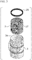
FIG. 3] FIG. 3 is a perspective view showing a liquid nitrogen absorber case and a case fixture which are taken out from the main body of a freezing transport container. - [
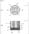
FIG. 4] FIG. 4 is a plan view (a) and a cross-sectional view (b) showing a liquid nitrogen absorber case disposed in a freezing transport container according to the embodiment of the present invention. - [
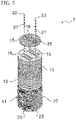
FIG. 5] FIG. 5 is an explanatory diagram showing a method for installing a liquid nitrogen absorbent material in a liquid nitrogen absorber case. - [
FIG. 6] FIG. 6 is an explanatory diagram showing sample insertion holes according to another embodiment which are provided in a liquid nitrogen absorber installed in a freezing transport container of the present invention. - [
FIG. 7] FIG. 7 is an explanatory diagram of a liquid nitrogen absorber case according to another embodiment which is provided in a freezing transport container of the present invention. - [
FIG. 8] FIG. 8 is an explanatory diagram showing an internal heat-transfer state in a freezing transport container according to an embodiment of the present invention. - [
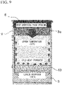
FIG. 9] FIG. 9 is an explanatory diagram showing an internal heat-transfer state in a conventional freezing transport container which does not include the liquid nitrogen absorber case. - A freezing transport container according to the present embodiment will be described with reference to
FIGS. 1 to 6 . In the following description, a case in which a main body of the freezing transport container is cylindrical will be taken as an example, and liquid nitrogen will be taken as an example of a cryogenic liquefied gas. However, the present invention is not limited thereto. - As shown in
FIGS. 1 to 6 , afreezing transport container 1 according to the present embodiment is for transporting a sample while maintaining it in a frozen state. Thefreezing transport container 1 according to the present embodiment includes amain body 3 having a heat-insulating structure, anopening 3a at the top, and a bottomed cylindrical shape; alid 5 which can open and close the opening 3a of themain body 3; and a liquidnitrogen absorber case 7 which is removably installed at the bottom of themain body 3. - Below, each configuration will be explained in detail.
- A sample is a biological sample mainly contained in a vial, a blood bag, and the like. The volume of the vial, the bag, and the like. is, for example, 25 ml, 50 ml, and 100 ml. The
freezing transport container 1 contains 10 or about 10 of the vials, the bags, and the like. - The
main body 3 has a heat-insulating structure, theopening 3a at the upper end, and a bottomed cylindrical shape as shown inFIGS. 1 to 3 . The diameter of theopening 3a at the upper end and the diameter of the bottom of themain body 3 are the same. Themain body 3 preferably has a vacuum double structure made of stainless steel. - An example of the external dimensions of the
main body 3 is as follows.External dimensions: ϕ 200 x H 300 mm Opening and bottom: ϕ 189 mm - The
lid 5 is attached on theopening 3a of themain body 3 so as to be openable and closable. Further, as shown inFIG. 1 , thelid body 5 has acylindrical portion 9 having the same diameter as that of theopening 3a. Thecylindrical portion 9 is inserted into theopening 3a of themain body 3. Thecylindrical portion 9 is formed by, for example, a heat-insulating material, such as polyurethane foam and polystyrene foam to prevent heat from entering through theopening 3a. - As shown in
FIG. 4 , the liquidnitrogen absorber case 7 includes a bottomedcylindrical case portion 11 and aliquid nitrogen absorber 13 replaceably installed inside thecase portion 11. The liquidnitrogen absorber case 7 is removably installed at the bottom of themain body 3. - The
liquid nitrogen absorber 13 is formed of a plurality of circular sheets. As shown inFIGS. 4 and5 , the circular sheets are arranged so as to be stacked on the bottom of thecase portion 11. - The
liquid nitrogen absorber 13 is, for example, made of polypropylene, and has a diameter of ϕ180 mm, and a thickness of 50 mm when the plurality of circular sheets are stacked. - The
liquid nitrogen absorber 13 is provided with a plurality ofholes 15 in order to increase the speed at which liquid nitrogen is immersed therein (seeFIG. 5 ). Further, the plurality ofholes 15 can be directly inserted with a vial-shaped sample, and also function as a sample insertion hole. - The shape of the
hole 15 is not limited to a circular shape when the sample or the like is a vial, and may be, for example, a rectangular shape into which a bag-shapedsample 16 is inserted, as shown inFIG. 6 . - When the
hole 15 provided in theliquid nitrogen absorber 13 functions as a sample insertion hole, the liquidnitrogen absorber case 7 is preferably provided with a fixingplate 19 described later and shown inFIGS. 4 and5 . The fixingplate 19 is provided with anopening 17 having the same shape as that of thehole 15 provided in theliquid nitrogen absorber 13 at a position corresponding to thehole 15 provided in theliquid nitrogen absorber 13. - The fixing
plate 19 is placed on the upper surface of theliquid nitrogen absorber 13. The fixingplate 19 is fixed to thecase portion 11 by a fixingscrew 23 and aspacer 21 provided so as to penetrate the stackedliquid nitrogen absorber 13 in the thickness direction. As a result, theliquid nitrogen absorber 13 formed by stacking a plurality of sheets is fixed inside thecase portion 11. A method for fixing theliquid nitrogen absorber 13 using thespacer 21 and the fixingplate 19 will be described in more detail as follows. - The
spacer 21 is a thin cylindrical metal fitting, and is threaded inside. A screw hole corresponding to thespacer 21 is formed at the bottom of thecase portion 11. First, the fixingscrew 23 is screwed into thespacer 21 from the lower surface side of the bottom of thecase portion 11. As a result, thespacer 21 is erected on the bottom of thecase portion 11. Next, theliquid nitrogen absorber 13 made of the plurality of sheets is placed in thecase portion 11. Since theliquid nitrogen absorber 13 has a spacer insertion hole formed in a portion corresponding to thespacer 21, theliquid nitrogen absorber 13 is placed so that the spacer is inserted into the spacer insertion hole. After placing, the fixingplate 19 is arranged on theliquid nitrogen absorber 13, and the fixingscrew 23 is screwed into thespacer 21 from the upper surface side of the fixingplate 19. Thereby, theliquid nitrogen absorber 13 can be attached into thecase portion 11 by thespacer 21 and the fixingplate 19. By disposing the fixingplate 19, theliquid nitrogen absorber 13 is sandwiched between the bottom of thecase portion 11 and the fixingplate 19 and does not fall off from thecase portion 11. - When replacing the
liquid nitrogen absorber 13, the liquidnitrogen absorber case 7 may be taken out from themain body 3 and the fixingplate 19 may be removed. - In addition to the insertion holes for the fixing
screw 23, the fixingplate 19 is provided with a large number of passage holes 25 through which liquid nitrogen passes when theliquid nitrogen absorber 13 is impregnated with the liquid nitrogen. - Further, as described above, when the
hole 15 provided in theliquid nitrogen absorber 13 functions as a sample insertion hole, the fixingplate 19 is provided with anopening 17. Theopening 17 is provided at a position corresponding to thehole 15 provided in theliquid nitrogen absorber 13. For example, a sample such as a vial can be inserted into theopening 17. - The fixing
plate 19 is formed by a metal heat conductor having high thermal conductivity such as aluminum, and copper, similar to thecase portion 11 described later. - As shown in
FIG. 4 , thecase portion 11 has a bottom portion and aside wall portion 27 provided upright from the periphery of the bottom portion. Theside wall portion 27 is preferably arranged so that the outer peripheral surface thereof is in contact with the inner peripheral wall of themain body 3. That is, it is preferable that there be no space between the inner peripheral wall of themain body 3 and theside wall portion 27 of thecase portion 11. As a result, a wide sample storage space can be secured. Furthermore, since there is no space, for example, an air layer, the heat-insulation efficiency can be improved. - The
case portion 11 having theside wall portion 27 and the bottom portion is formed of a heat conductor, for example, metal having high thermal conductivity, such as aluminum and copper. By using a metal having high thermal conductivity, the cold heat of liquid nitrogen can be transferred to the upper part of the container faster and cool the upper part of the container. When themain body 3 is made of stainless steel, thecase portion 11 is more preferably made of aluminum, which is less likely to rust. - An example of the dimensions of the
case portion 11 is ϕ183 mm × H 200 mm. The thickness of the case portion is 0.5 mm, and the inner diameter of theside wall portion 27 is ϕ182 mm. - Although the description above illustrates the case in which the bottom of the
case portion 11 is circular, the shape is not limited to a circular shape, and a shape such as a quadrangle or a polygon can be selected according to the application and the shape of themain body 3. - The
case portion 11 has a function of transmitting the cold heat of theliquid nitrogen absorber 13 and effectively cooling the sample contained therein. When thecase portion 11 having such functions comes into contact with thecylindrical portion 9 made of the heat-insulating material in thelid 5, the heat of the heat-insulating material itself is transferred to the inside of the container. Therefore, it is preferable that thecase portion 11 and thecylindrical portion 9 not come into contact with each other, and it is preferable to set a gap of 2 to 3 mm between them. - When the
side wall portion 27 of thecase portion 11 has a height such that the upper end thereof is the same as the upper end of the inner wall surface of themain body 3, the cold heat of liquid nitrogen can be efficiently transmitted to the upper portion of themain body 3. Therefore, the inside of themain body 3 can be kept at a lower temperature. - On the other hand, as described above, the amount of evaporation loss of liquid nitrogen increases because the heat from the
opening 3a is easily transferred to the inside of the container. - Therefore, it is preferable that the height of the side wall portion of the
case portion 11 satisfy the following relationship. - (Distance from the upper end of the
liquid nitrogen absorber 13 to the bottom of thecylindrical portion 9 of lid 5) : (Height of the side wall portion 27) is preferably 100: 0 to 95, and more preferably 100: 70 to 90. - When (Distance from the upper end of the
liquid nitrogen absorber 13 to the bottom of thecylindrical portion 9 of lid 5) : (Height of the side wall portion 27) is 100: 0, as shown inFIG. 7 , the height of theside wall portion 27 of thecase portion 11 is the same as the height of theliquid nitrogen absorber 13. When the height of the storage portion in themain body 3 is low, even if the height of theside wall portion 27 of thecase portion 11 is the same as the height of theliquid nitrogen absorber 13, the storage space (holes 15 provided in the liquid nitrogen absorber 13) is sufficiently cooled by vaporized nitrogen. When the sample is inserted into thehole 15 of theliquid nitrogen absorber 13, the height of theside wall portion 27 of thecase portion 11 may be the same as the height of theliquid nitrogen absorber 13. - In order to secure a wide space, it is preferable that the outer diameter of the
side wall portion 27 of thecase portion 11 be substantially the same as the inner diameter of themain body 3. - Further, when it is desired to rapidly cool the inside of the freezing
transport container 1 or lower the temperature, fins may be provided on the inner wall of theside wall portion 27 in order to improve the heat-transfer performance. - The liquid
nitrogen absorber case 7 is installed removably in themain body 3, and it is preferable that the liquidnitrogen absorber case 7 can be taken out easily. For example, it is preferable to use anannular case fixture 29 which is detachably attached in the vicinity of theopening 3a of the main body 3 (seeFIGS. 1 and3 ). - The outer diameter of the
case fixture 29 is preferably slightly larger than the inner diameter of theopening 3a of themain body 3. Further, thecase fixture 29 is preferably formed of a heat-insulating and flexible member such as polyurethane foam and polystyrene foam. As shown inFIG. 1 , thecase fixture 29 is attached in the vicinity of theopening 3a of themain body 3 in a state in which the liquidnitrogen absorber case 7 is arranged inside themain body 3. - Since the outer diameter of the
case fixture 29 is slightly larger than the inner diameter of themain body 3, thecase fixture 29 is detachably attached to themain body 3 in a compressed state. In this way, thecase fixture 29 is press-fitted into themain body 3 and is arranged in close contact with the inner wall of themain body 3 at the upper part of the liquidnitrogen absorber case 7. Accordingly, even if the freezingtransport container 1 is tilted, the liquidnitrogen absorber case 7 will not come out. - On the other hand, when the liquid
nitrogen absorber case 7 is taken out in order to exchange theliquid nitrogen absorber 13 or the like, thecase fixture 29 may be slightly bent and removed. - As described above, in the freezing
transport container 1 of the present embodiment, the liquidnitrogen absorber case 7 can be taken out and theliquid nitrogen absorber 13 can be easily replaced. Therefore, if theliquid nitrogen absorber 13 is deteriorated or contaminated, it can be replaced. - When the height of the
side wall portion 27 of thecase portion 11 is higher than the height of theliquid nitrogen absorber 13, since theside wall portion 27 is along the inner wall of themain body 3, and theliquid nitrogen absorber 13 is arranged only at the bottom of theportion 11, the internal space is wide and a large sample such as a bag can be accommodated, which makes it possible to transport a large sample, which has been difficult in the past. - For example, a 50 ml bag-shaped sample requires a space of 95 mm (length) x 85 mm (width) x 10 mm (thickness). The diameter of the opening of a part of the conventional general dry shipper is narrower than the outer diameter. For example, the opening is designed to have a diameter of 50 mm to 70 mm. Therefore, a bag-shaped sample cannot be stored in a dry shipper having such dimensions. Alternatively, in order to store the bag-shaped sample in a dry shipper of which the opening diameter is smaller than the outer diameter, a dry shipper having a larger outer diameter must be used. Therefore, there are inconveniences such as an increase in the amount of liquid nitrogen used.
- On the other hand, in the present embodiment, since the diameter of the opening and the diameter of the bottom of the
main body 3 are the same, theopening 3a is ϕ189 mm, and the inner diameter of theside wall portion 27 is ϕ182 mm, it is possible to store the samples in the mode shown inFIG. 6 . - Further, when the height of the
side wall portion 27 of thecase portion 11 is larger than the height of theliquid nitrogen absorber 13, it is possible to maintain a low temperature without narrowing the content volume of the upper part of the container storage space in which the temperature does not easily drop due to the heat-transfer from thelid 5 and the influence of the outside air temperature. -
FIG. 8 shows the temperature inside the freezingtransport container 1 of the present embodiment. A temperature of about -150°C can be realized even in the upper part of theside wall portion 27. - That is, in a conventional freezing transport container, an impregnating material (liquid nitrogen absorber) is arranged on the bottom portion and the inner peripheral wall of the
main body 3 which is a heat-insulating container. On the other hand, the freezingtransport container 1 of the present embodiment includes the bottomedtubular case portion 11 having aside wall portion 27, and theliquid nitrogen absorber 13 is installed in thecase portion 11. In particular, when the height of theside wall portion 27 is higher than the height of theliquid nitrogen absorber 13, the sample storage space is kept large in volume and kept at a low temperature. - When the
liquid nitrogen absorber 13 is installed on the bottom of themain body 3 having the same shape as that of the liquidnitrogen adsorber case 7 without providing the liquidnitrogen absorber case 7 in themain body 3, that is, in a conventional freezing transport container, the cold heat of theliquid nitrogen absorber 13 is transmitted to the inner wall of themain body 3 which is formed by stainless steel. However, since stainless steel has a low thermal conductivity, the upper part does not easily cool. Accordingly, as shown inFIG. 9 , the temperature at the upper part is only about -30°C. From this result, a great effect can be expected when thecase portion 11 includes theside wall portion 27 having a height larger than the height of theliquid nitrogen absorber 13. - Since the freezing transport container shown in
FIG. 9 does not have the liquidnitrogen absorber case 7, thecase fixture 29 is unnecessary, and thecase fixture 29 is also not provided. - In the case of the freezing
transport container 1 shown inFIG. 8 , it took about 30 minutes for the temperature inside themain body 3 to reach -150°C or lower after the liquidnitrogen absorber case 7 had been installed in themain body 3, and the temperature inside themain body 3 could be maintained at -150°C or lower for about 300 minutes. - In the embodiment above, an example in which the
main body 3 of the freezingtransport container 1 has a cylindrical shape has been described. In this case, the liquidnitrogen absorber case 7 installed in themain body 3 also has a similar cylindrical shape. - However, the
main body 3 of the freezingtransport container 1 is not limited to a cylindrical shape, and may be, for example, a rectangular tubular shape. In this case, it is preferable that the liquidnitrogen absorber case 7 installed in themain body 3 also have the same rectangular tubular shape. - Further, in the embodiment above, liquid nitrogen is taken as an example as the cryogenic liquefied gas. However, the cryogenic liquefied gas used in the present invention is not limited to liquid nitrogen, and as long as a suitable absorbent material is used, a liquefied gas of an inert gas such as liquid helium and liquid argon can also be used.
-
- 1
- freezing transport container
- 3
- main body
- 3a
- opening
- 5
- lid
- 7
- liquid nitrogen absorber case
- 9
- cylindrical portion
- 11
- case portion
- 13
- liquid nitrogen absorber
- 15
- hole
- 16
- bag-shaped sample
- 17
- opening
- 19
- fixing plate
- 21
- spacer
- 23
- fixing screw
- 25
- passing hole
- 27
- side wall portion
- 29
- case fixture
Claims (7)
- A freezing transport container including a main body which has a heat-insulating structure, an opening at the top, and a bottomed tubular shape, and a lid which is installed at the opening of the main body so as to open and close the opening of the main body,wherein the main body has the same diameter at the opening at the top and the bottom,the freezing transport container further includes a cryogenic liquefied gas absorber case which is installed removably at the bottom of the main body, andthe cryogenic liquefied gas absorber case includes a case portion which has a bottomed tubular shape and a cryogenic liquefied gas absorber which is installed replaceably inside the case portion.
- The freezing transport container according to Claim 1,wherein the case portion is formed by a heat conductor, has a side wall portion arranged along the inner peripheral wall of the main body, and an inner space of the side wall portion functions as a sample storage portion, anda height of the side wall portion is higher than a height of the cryogenic liquefied gas absorber.
- The freezing transport container according to Claim 1 or 2,
wherein the main body having a heat-insulating structure has a vacuum double structure formed by stainless steel, and the case portion is made of aluminum or copper. - The freezing transport container according to any one of Claims 1 to 3,
wherein the case portion includes a fixing plate, and the fixing plate and the cryogenic liquefied gas absorber are provided with a sample insertion hole which is configured to be received with a sample to be stored. - A cryogenic liquefied gas absorber case which is configured to be installed removably on the bottom of a freezing transport container including a main body which has a heat-insulating structure, an opening at the top, a bottomed tubular shape, and the same diameter at the opening at the top and the bottom, and a lid which is installed into the opening in the main body so as to open and close the opening of the main body,
wherein the cryogenic liquefied gas absorber case includes a case portion which has a bottomed tubular shape, and a cryogenic liquefied gas absorber which is installed replaceably inside the case portion. - A cryogenic liquefied gas absorber case according to Claim 5,wherein the case portion is formed by a heat conductor and has a side wall portion arranged along an inner peripheral wall of the main body,an inner space of the side wall portion functions as a sample storage portion, anda height of the side wall portion is higher than a height of the cryogenic liquefied gas absorber.
- The cryogenic liquefied gas absorber case according to Claim 5 or 7,
wherein the case portion is formed by aluminum or copper.
Applications Claiming Priority (2)
| Application Number | Priority Date | Filing Date | Title |
|---|---|---|---|
| JP2019110855A JP7272874B2 (en) | 2019-06-14 | 2019-06-14 | Frozen transport container, cryogenic liquefied gas absorbent case |
| PCT/JP2020/023187 WO2020251010A1 (en) | 2019-06-14 | 2020-06-12 | Freezing transport container, and cryogenic liquefied gas absorber case |
Publications (3)
| Publication Number | Publication Date |
|---|---|
| EP3984908A1 true EP3984908A1 (en) | 2022-04-20 |
| EP3984908A4 EP3984908A4 (en) | 2023-07-05 |
| EP3984908B1 EP3984908B1 (en) | 2026-04-08 |
Family
ID=73781264
Family Applications (1)
| Application Number | Title | Priority Date | Filing Date |
|---|---|---|---|
| EP20822402.2A Active EP3984908B1 (en) | 2019-06-14 | 2020-06-12 | Freezing transport container, and cryogenic liquefied gas absorber case |
Country Status (4)
| Country | Link |
|---|---|
| US (1) | US12292233B2 (en) |
| EP (1) | EP3984908B1 (en) |
| JP (1) | JP7272874B2 (en) |
| WO (1) | WO2020251010A1 (en) |
Families Citing this family (1)
| Publication number | Priority date | Publication date | Assignee | Title |
|---|---|---|---|---|
| CN116269995A (en) * | 2022-09-08 | 2023-06-23 | 青岛澳柯玛生物医疗有限公司 | A horizontal cold therapy device |
Family Cites Families (12)
| Publication number | Priority date | Publication date | Assignee | Title |
|---|---|---|---|---|
| EP1356229A4 (en) * | 2000-12-29 | 2009-11-18 | Cryoport Systems Llc | CRYOGENIC EXPEDITION CONTAINER |
| GB2377985A (en) * | 2001-04-03 | 2003-01-29 | Brian Clarke | A disposable container for refrigerated animal/human tissue or fluid |
| JP4881046B2 (en) | 2006-03-30 | 2012-02-22 | 独立行政法人海洋研究開発機構 | Cryopreservation |
| JP5026142B2 (en) * | 2007-05-16 | 2012-09-12 | 大陽日酸株式会社 | Cryopreservation container |
| WO2012088311A2 (en) * | 2010-12-21 | 2012-06-28 | Savsu Technologies Llc | Insulated storage system with balanced thermal energy flow |
| JP5534116B1 (en) * | 2012-08-16 | 2014-06-25 | 株式会社ミラプロ | Metal sealed double container |
| JP6689583B2 (en) * | 2015-07-31 | 2020-04-28 | 大陽日酸株式会社 | Storage tools, storage racks and storage shelves for sheet-like biological samples |
| WO2017083164A1 (en) * | 2015-11-10 | 2017-05-18 | Entegris, Inc. | Dry shipping container |
| CN205352821U (en) * | 2015-12-30 | 2016-06-29 | 妙通(上海)生物科技有限公司 | Portable biological sample liquid nitrogen freezes storage |
| JP6653283B2 (en) * | 2016-03-15 | 2020-02-26 | 大陽日酸株式会社 | Biological sample transport container |
| US10542744B2 (en) * | 2017-04-11 | 2020-01-28 | Fisher Bioservices Inc. | Cryogenic storage rack including rotatable shelves, and associated storage systems and methods |
| US11596148B2 (en) * | 2017-11-17 | 2023-03-07 | Savsu Technologies, Inc. | Dry vapor cryogenic container with absorbent core |
-
2019
- 2019-06-14 JP JP2019110855A patent/JP7272874B2/en active Active
-
2020
- 2020-06-12 EP EP20822402.2A patent/EP3984908B1/en active Active
- 2020-06-12 WO PCT/JP2020/023187 patent/WO2020251010A1/en not_active Ceased
- 2020-06-12 US US17/614,809 patent/US12292233B2/en active Active
Also Published As
| Publication number | Publication date |
|---|---|
| JP2020204476A (en) | 2020-12-24 |
| US12292233B2 (en) | 2025-05-06 |
| US20220228789A1 (en) | 2022-07-21 |
| WO2020251010A1 (en) | 2020-12-17 |
| JP7272874B2 (en) | 2023-05-12 |
| EP3984908A4 (en) | 2023-07-05 |
| EP3984908B1 (en) | 2026-04-08 |
Similar Documents
| Publication | Publication Date | Title |
|---|---|---|
| US10995980B2 (en) | Cryovial storage system | |
| JP6653283B2 (en) | Biological sample transport container | |
| US8956855B2 (en) | Portable cryogenic container | |
| US10618695B2 (en) | Contents rack for use in insulated storage containers | |
| JP3958213B2 (en) | Cryogenic shipping container | |
| JP5026142B2 (en) | Cryopreservation container | |
| CN101473179A (en) | Transport container for maintaining the temperature of frozen goods | |
| US12013177B2 (en) | Container for cryopreservation and transportation | |
| US10378695B2 (en) | Cryogenic storage container | |
| US11596148B2 (en) | Dry vapor cryogenic container with absorbent core | |
| JP7591318B2 (en) | Apparatus for storing and transporting biological samples under cryogenic conditions - Patents.com | |
| EP3984908B1 (en) | Freezing transport container, and cryogenic liquefied gas absorber case | |
| JP2006038220A (en) | Cryogenic dewar bottle | |
| EP1223393A2 (en) | Liquid cryogen storage container | |
| JP6689583B2 (en) | Storage tools, storage racks and storage shelves for sheet-like biological samples | |
| JP2006030144A (en) | Sample tube heat-insulating tray and heat insulating box for multi-well plate | |
| US7290396B2 (en) | Cryogenic biological preservation unit | |
| JP2018054420A (en) | Cryopreservation instrument | |
| US12429272B2 (en) | System and method for insulated cryogenic shipper | |
| JP7539610B2 (en) | Fixing device for transporting samples in vacuum insulated double containers | |
| US20020083718A1 (en) | Specimen chamber for a cryogenic shipping container | |
| CN210610866U (en) | Vegetable or grain and oil fresh-keeping device for long-distance transportation | |
| CN213362944U (en) | High-efficient freezing box | |
| KR20040020587A (en) | Rapid freezing apparatus for living body tissue | |
| KR200297342Y1 (en) | Rapid freezing apparatus for living body tissue |
Legal Events
| Date | Code | Title | Description |
|---|---|---|---|
| STAA | Information on the status of an ep patent application or granted ep patent |
Free format text: STATUS: THE INTERNATIONAL PUBLICATION HAS BEEN MADE |
|
| PUAI | Public reference made under article 153(3) epc to a published international application that has entered the european phase |
Free format text: ORIGINAL CODE: 0009012 |
|
| STAA | Information on the status of an ep patent application or granted ep patent |
Free format text: STATUS: REQUEST FOR EXAMINATION WAS MADE |
|
| 17P | Request for examination filed |
Effective date: 20211122 |
|
| AK | Designated contracting states |
Kind code of ref document: A1 Designated state(s): AL AT BE BG CH CY CZ DE DK EE ES FI FR GB GR HR HU IE IS IT LI LT LU LV MC MK MT NL NO PL PT RO RS SE SI SK SM TR |
|
| DAV | Request for validation of the european patent (deleted) | ||
| DAX | Request for extension of the european patent (deleted) | ||
| REG | Reference to a national code |
Ref country code: DE Ref legal event code: R079 Free format text: PREVIOUS MAIN CLASS: B65D0081180000 Ipc: A01N0001020000 Ref document number: 602020070124 Country of ref document: DE |
|
| A4 | Supplementary search report drawn up and despatched |
Effective date: 20230607 |
|
| RIC1 | Information provided on ipc code assigned before grant |
Ipc: A01N 1/02 20060101AFI20230601BHEP |
|
| REG | Reference to a national code |
Ref country code: DE Free format text: PREVIOUS MAIN CLASS: A01N0001020000 Ref country code: DE Ref legal event code: R079 Ref document number: 602020070124 Country of ref document: DE Free format text: PREVIOUS MAIN CLASS: A01N0001020000 Ipc: A01N0001145000 |
|
| GRAP | Despatch of communication of intention to grant a patent |
Free format text: ORIGINAL CODE: EPIDOSNIGR1 |
|
| STAA | Information on the status of an ep patent application or granted ep patent |
Free format text: STATUS: GRANT OF PATENT IS INTENDED |
|
| RIC1 | Information provided on ipc code assigned before grant |
Ipc: A01N 1/145 20250101AFI20251218BHEP Ipc: C12N 5/00 20060101ALI20251218BHEP |
|
| INTG | Intention to grant announced |
Effective date: 20260105 |
|
| GRAS | Grant fee paid |
Free format text: ORIGINAL CODE: EPIDOSNIGR3 |
|
| GRAA | (expected) grant |
Free format text: ORIGINAL CODE: 0009210 |
|
| STAA | Information on the status of an ep patent application or granted ep patent |
Free format text: STATUS: THE PATENT HAS BEEN GRANTED |
|
| AK | Designated contracting states |
Kind code of ref document: B1 Designated state(s): AL AT BE BG CH CY CZ DE DK EE ES FI FR GB GR HR HU IE IS IT LI LT LU LV MC MK MT NL NO PL PT RO RS SE SI SK SM TR |
|
| REG | Reference to a national code |
Ref country code: CH Ref legal event code: F10 Free format text: ST27 STATUS EVENT CODE: U-0-0-F10-F00 (AS PROVIDED BY THE NATIONAL OFFICE) Effective date: 20260408 Ref country code: GB Ref legal event code: FG4D |
|
| REG | Reference to a national code |
Ref country code: DE Ref legal event code: R096 Ref document number: 602020070124 Country of ref document: DE |