EP3984882A1 - Propeller and propeller blade - Google Patents
Propeller and propeller blade Download PDFInfo
- Publication number
- EP3984882A1 EP3984882A1 EP21172864.7A EP21172864A EP3984882A1 EP 3984882 A1 EP3984882 A1 EP 3984882A1 EP 21172864 A EP21172864 A EP 21172864A EP 3984882 A1 EP3984882 A1 EP 3984882A1
- Authority
- EP
- European Patent Office
- Prior art keywords
- propeller
- blade
- slot
- blade tip
- tip
- Prior art date
- Legal status (The legal status is an assumption and is not a legal conclusion. Google has not performed a legal analysis and makes no representation as to the accuracy of the status listed.)
- Granted
Links
Images


Classifications
-
- B—PERFORMING OPERATIONS; TRANSPORTING
- B64—AIRCRAFT; AVIATION; COSMONAUTICS
- B64C—AEROPLANES; HELICOPTERS
- B64C11/00—Propellers, e.g. of ducted type; Features common to propellers and rotors for rotorcraft
- B64C11/16—Blades
- B64C11/18—Aerodynamic features
-
- B—PERFORMING OPERATIONS; TRANSPORTING
- B64—AIRCRAFT; AVIATION; COSMONAUTICS
- B64C—AEROPLANES; HELICOPTERS
- B64C11/00—Propellers, e.g. of ducted type; Features common to propellers and rotors for rotorcraft
- B64C11/16—Blades
-
- B—PERFORMING OPERATIONS; TRANSPORTING
- B22—CASTING; POWDER METALLURGY
- B22F—WORKING METALLIC POWDER; MANUFACTURE OF ARTICLES FROM METALLIC POWDER; MAKING METALLIC POWDER; APPARATUS OR DEVICES SPECIALLY ADAPTED FOR METALLIC POWDER
- B22F5/00—Manufacture of workpieces or articles from metallic powder characterised by the special shape of the product
-
- B—PERFORMING OPERATIONS; TRANSPORTING
- B33—ADDITIVE MANUFACTURING TECHNOLOGY
- B33Y—ADDITIVE MANUFACTURING, i.e. MANUFACTURING OF THREE-DIMENSIONAL [3D] OBJECTS BY ADDITIVE DEPOSITION, ADDITIVE AGGLOMERATION OR ADDITIVE LAYERING, e.g. BY 3D PRINTING, STEREOLITHOGRAPHY OR SELECTIVE LASER SINTERING
- B33Y80/00—Products made by additive manufacturing
-
- B—PERFORMING OPERATIONS; TRANSPORTING
- B64—AIRCRAFT; AVIATION; COSMONAUTICS
- B64C—AEROPLANES; HELICOPTERS
- B64C23/00—Influencing air flow over aircraft surfaces, not otherwise provided for
- B64C23/06—Influencing air flow over aircraft surfaces, not otherwise provided for by generating vortices
-
- B—PERFORMING OPERATIONS; TRANSPORTING
- B64—AIRCRAFT; AVIATION; COSMONAUTICS
- B64C—AEROPLANES; HELICOPTERS
- B64C27/00—Rotorcraft; Rotors peculiar thereto
- B64C27/32—Rotors
- B64C27/46—Blades
- B64C27/463—Blade tips
-
- F—MECHANICAL ENGINEERING; LIGHTING; HEATING; WEAPONS; BLASTING
- F01—MACHINES OR ENGINES IN GENERAL; ENGINE PLANTS IN GENERAL; STEAM ENGINES
- F01D—NON-POSITIVE DISPLACEMENT MACHINES OR ENGINES, e.g. STEAM TURBINES
- F01D5/00—Blades; Blade-carrying members; Heating, heat-insulating, cooling or antivibration means on the blades or the members
-
- F—MECHANICAL ENGINEERING; LIGHTING; HEATING; WEAPONS; BLASTING
- F01—MACHINES OR ENGINES IN GENERAL; ENGINE PLANTS IN GENERAL; STEAM ENGINES
- F01D—NON-POSITIVE DISPLACEMENT MACHINES OR ENGINES, e.g. STEAM TURBINES
- F01D5/00—Blades; Blade-carrying members; Heating, heat-insulating, cooling or antivibration means on the blades or the members
- F01D5/12—Blades
- F01D5/14—Form or construction
- F01D5/141—Shape, i.e. outer, aerodynamic form
- F01D5/146—Shape, i.e. outer, aerodynamic form of blades with tandem configuration, split blades or slotted blades
-
- F—MECHANICAL ENGINEERING; LIGHTING; HEATING; WEAPONS; BLASTING
- F03—MACHINES OR ENGINES FOR LIQUIDS; WIND, SPRING, OR WEIGHT MOTORS; PRODUCING MECHANICAL POWER OR A REACTIVE PROPULSIVE THRUST, NOT OTHERWISE PROVIDED FOR
- F03D—WIND MOTORS
- F03D1/00—Wind motors with rotation axis substantially parallel to the air flow entering the rotor
- F03D1/06—Rotors
- F03D1/0608—Rotors characterised by their aerodynamic shape
- F03D1/0633—Rotors characterised by their aerodynamic shape of the blades
-
- F—MECHANICAL ENGINEERING; LIGHTING; HEATING; WEAPONS; BLASTING
- F04—POSITIVE - DISPLACEMENT MACHINES FOR LIQUIDS; PUMPS FOR LIQUIDS OR ELASTIC FLUIDS
- F04D—NON-POSITIVE-DISPLACEMENT PUMPS
- F04D29/00—Details, component parts, or accessories
- F04D29/26—Rotors specially for elastic fluids
- F04D29/32—Rotors specially for elastic fluids for axial flow pumps
- F04D29/38—Blades
- F04D29/384—Blades characterised by form
-
- F—MECHANICAL ENGINEERING; LIGHTING; HEATING; WEAPONS; BLASTING
- F04—POSITIVE - DISPLACEMENT MACHINES FOR LIQUIDS; PUMPS FOR LIQUIDS OR ELASTIC FLUIDS
- F04D—NON-POSITIVE-DISPLACEMENT PUMPS
- F04D29/00—Details, component parts, or accessories
- F04D29/66—Combating cavitation, whirls, noise, vibration or the like; Balancing
- F04D29/68—Combating cavitation, whirls, noise, vibration or the like; Balancing by influencing boundary layers
- F04D29/681—Combating cavitation, whirls, noise, vibration or the like; Balancing by influencing boundary layers especially adapted for elastic fluid pumps
-
- F—MECHANICAL ENGINEERING; LIGHTING; HEATING; WEAPONS; BLASTING
- F04—POSITIVE - DISPLACEMENT MACHINES FOR LIQUIDS; PUMPS FOR LIQUIDS OR ELASTIC FLUIDS
- F04D—NON-POSITIVE-DISPLACEMENT PUMPS
- F04D29/00—Details, component parts, or accessories
- F04D29/66—Combating cavitation, whirls, noise, vibration or the like; Balancing
- F04D29/68—Combating cavitation, whirls, noise, vibration or the like; Balancing by influencing boundary layers
- F04D29/681—Combating cavitation, whirls, noise, vibration or the like; Balancing by influencing boundary layers especially adapted for elastic fluid pumps
- F04D29/682—Combating cavitation, whirls, noise, vibration or the like; Balancing by influencing boundary layers especially adapted for elastic fluid pumps by fluid extraction
-
- F—MECHANICAL ENGINEERING; LIGHTING; HEATING; WEAPONS; BLASTING
- F04—POSITIVE - DISPLACEMENT MACHINES FOR LIQUIDS; PUMPS FOR LIQUIDS OR ELASTIC FLUIDS
- F04D—NON-POSITIVE-DISPLACEMENT PUMPS
- F04D29/00—Details, component parts, or accessories
- F04D29/66—Combating cavitation, whirls, noise, vibration or the like; Balancing
- F04D29/68—Combating cavitation, whirls, noise, vibration or the like; Balancing by influencing boundary layers
- F04D29/681—Combating cavitation, whirls, noise, vibration or the like; Balancing by influencing boundary layers especially adapted for elastic fluid pumps
- F04D29/684—Combating cavitation, whirls, noise, vibration or the like; Balancing by influencing boundary layers especially adapted for elastic fluid pumps by fluid injection
-
- F—MECHANICAL ENGINEERING; LIGHTING; HEATING; WEAPONS; BLASTING
- F01—MACHINES OR ENGINES IN GENERAL; ENGINE PLANTS IN GENERAL; STEAM ENGINES
- F01D—NON-POSITIVE DISPLACEMENT MACHINES OR ENGINES, e.g. STEAM TURBINES
- F01D5/00—Blades; Blade-carrying members; Heating, heat-insulating, cooling or antivibration means on the blades or the members
- F01D5/12—Blades
- F01D5/14—Form or construction
- F01D5/141—Shape, i.e. outer, aerodynamic form
- F01D5/145—Means for influencing boundary layers or secondary circulations
-
- F—MECHANICAL ENGINEERING; LIGHTING; HEATING; WEAPONS; BLASTING
- F05—INDEXING SCHEMES RELATING TO ENGINES OR PUMPS IN VARIOUS SUBCLASSES OF CLASSES F01-F04
- F05B—INDEXING SCHEME RELATING TO WIND, SPRING, WEIGHT, INERTIA OR LIKE MOTORS, TO MACHINES OR ENGINES FOR LIQUIDS COVERED BY SUBCLASSES F03B, F03D AND F03G
- F05B2240/00—Components
- F05B2240/20—Rotors
- F05B2240/30—Characteristics of rotor blades, i.e. of any element transforming dynamic fluid energy to or from rotational energy and being attached to a rotor
- F05B2240/307—Blade tip, e.g. winglets
-
- F—MECHANICAL ENGINEERING; LIGHTING; HEATING; WEAPONS; BLASTING
- F05—INDEXING SCHEMES RELATING TO ENGINES OR PUMPS IN VARIOUS SUBCLASSES OF CLASSES F01-F04
- F05D—INDEXING SCHEME FOR ASPECTS RELATING TO NON-POSITIVE-DISPLACEMENT MACHINES OR ENGINES, GAS-TURBINES OR JET-PROPULSION PLANTS
- F05D2220/00—Application
- F05D2220/30—Application in turbines
- F05D2220/36—Application in turbines specially adapted for the fan of turbofan engines
-
- Y—GENERAL TAGGING OF NEW TECHNOLOGICAL DEVELOPMENTS; GENERAL TAGGING OF CROSS-SECTIONAL TECHNOLOGIES SPANNING OVER SEVERAL SECTIONS OF THE IPC; TECHNICAL SUBJECTS COVERED BY FORMER USPC CROSS-REFERENCE ART COLLECTIONS [XRACs] AND DIGESTS
- Y02—TECHNOLOGIES OR APPLICATIONS FOR MITIGATION OR ADAPTATION AGAINST CLIMATE CHANGE
- Y02E—REDUCTION OF GREENHOUSE GAS [GHG] EMISSIONS, RELATED TO ENERGY GENERATION, TRANSMISSION OR DISTRIBUTION
- Y02E10/00—Energy generation through renewable energy sources
- Y02E10/70—Wind energy
- Y02E10/72—Wind turbines with rotation axis in wind direction
-
- Y—GENERAL TAGGING OF NEW TECHNOLOGICAL DEVELOPMENTS; GENERAL TAGGING OF CROSS-SECTIONAL TECHNOLOGIES SPANNING OVER SEVERAL SECTIONS OF THE IPC; TECHNICAL SUBJECTS COVERED BY FORMER USPC CROSS-REFERENCE ART COLLECTIONS [XRACs] AND DIGESTS
- Y02—TECHNOLOGIES OR APPLICATIONS FOR MITIGATION OR ADAPTATION AGAINST CLIMATE CHANGE
- Y02T—CLIMATE CHANGE MITIGATION TECHNOLOGIES RELATED TO TRANSPORTATION
- Y02T50/00—Aeronautics or air transport
- Y02T50/10—Drag reduction
-
- Y—GENERAL TAGGING OF NEW TECHNOLOGICAL DEVELOPMENTS; GENERAL TAGGING OF CROSS-SECTIONAL TECHNOLOGIES SPANNING OVER SEVERAL SECTIONS OF THE IPC; TECHNICAL SUBJECTS COVERED BY FORMER USPC CROSS-REFERENCE ART COLLECTIONS [XRACs] AND DIGESTS
- Y02—TECHNOLOGIES OR APPLICATIONS FOR MITIGATION OR ADAPTATION AGAINST CLIMATE CHANGE
- Y02T—CLIMATE CHANGE MITIGATION TECHNOLOGIES RELATED TO TRANSPORTATION
- Y02T50/00—Aeronautics or air transport
- Y02T50/60—Efficient propulsion technologies, e.g. for aircraft
Definitions
- the present invention relates to a propeller for aircrafts, helicopters, wind turbines with horizontal axis, fans and drones, it also relates to a wide propeller blade.
- propellers, wind turbines with horizontal axis or fans can only be made with a limited diameter, the desired performance can be achieved by increasing the width of their blades. In this case, however, the flow conditions deteriorate and significant, undesirable vortices are generated at the wide tip of the blades. These obviously cause energy loss and efficiency degradation.
- An alternative or additional solution could be to increase the number of blades, but in the case of more than four blades arranged in one plane, the blades interfere with each other from a flow point of view.
- wing flap or wingtip device also known as a winglet
- a winglet which is a vertically positioned auxiliary wing flap or an upward extension of the wing located at the wing tips of some airplanes.
- the winglet reduces air vortices at the wing tip, which would otherwise significantly increase the air resistance of the wing of the aircraft.
- the winglet can only be used effectively in linear motion, therefore it is generally used on wings.
- Propeller blades used at aircrafts, helicopters or drones, as well as wind turbine blades of horizontal axis of rotation or fan blades also generate air vortices at the distal ends of the axis of rotation, which increase energy losses.
- the losses are particularly high if the tip of the blades are not taperingly pointed but wide.
- a vortex distribution plate placed at the end (tip) of wings or blades, similar to a winglet, is shown in document DE3816430 .
- the plate is arranged perpendicular to the longitudinal direction of the blade and is provided with holes to reduce the vortices at the the blade tip. The holes widen towards the outer edge of the plate, thus ensuring that the pressure difference between the pressure and suction side does not suddenly begin to equalize in order to maintain the buoyancy.
- US 2,160,323 discloses a propeller having a passage in the blade to reduce vacuum emerging on the suction side of the blade as well as the deriving noise and to increase efficiency.
- the passage connecting the pressure side of the blade to the suction side is elongated, the length of which is 70-80% that of the blade and is arranged substantially along the longitudinal axis of the blade. This patent document, however, does not specifically teach how to reduce flow losses at the blade tip.
- U.S. patent document 6,283,406 B1 discloses a noise reduction method for the noise generated by a helicopter rotor.
- inlets close to the leading edge and outlets close to the trailing edge, as well as passages connecting them are arranged near the surface of both the suction and the pressure sides.
- the passages do not connect the suction and pressure sides, but run substantially parallel to the sides of the blade and form slots that are not permanently permeable to air, but are controlled to open and close above a certain level of noise, pressure and speed.
- outlet openings are arranged at the blade tips in several places and directions, through which gas jets are led to accelerate the damping of the vortices at the blade tips.
- US 5,791,875 also teaches a relatively complex control device for reducing blade tip vortices.
- a vortex rotating in the opposite direction is created, and the medium for this purpose is guided to the wing tips in channels arranged in the wing, and in the rotor blade, where the medium is driven out with controlled pressure and in a controlled, curved path to form a counter-vortex.
- the solution described in the published EP3509945 A1 document can be considered as the closest piece of prior art, wherein the slots connecting the suction and the pressure sides are formed at the blade tips, specifically in order to eliminate the losses at the blade tips.
- the distance of the slot from the blade tip is given as a percentage of the length of the diameter, adapted to the size and location of the vortex cones formed at the blade tip, for extinguishing them by vortex interference.
- the slot is divided into sections with small interruptions.
- the disadvantage of the prior art wings and propellers is that they do not provide a solution to also ensure the maximum strength of the blade or the blade tip when designing a device for eliminating, reducing or stopping the vortices at the blade tip (or wing tip).
- Each of the referenced inventions has been created by material reliefs, omissions such as longitudinal gaps, holes, passages formed inside the blade, sometimes by also placing complex control elements which mean additional loads; however, there is no mention of strength aspects. Furthermore, they do not teach how to eliminate losses specifically due to pressure irregularities.
- the structure of the propeller blade or the propeller designed to reduce or eliminate flow losses at the blade tip should provide minimal air resistance and be of adequate strength to withstand centrifugal force.
- the object is achieved by providing a propeller blade applicable for a propeller for aircrafts, helicopters, wind turbines with horizontal axis, fans and drones, the propeller rotating in a determined rotational direction about an axis of rotation; wherein the propeller blade, has a pressure side, a suction side opposite thereto, a blade root adapted to be connected to the propeller, a blade tip at the opposite end with respect to the blade root; wherein a slot is formed within the propeller blade connecting the pressure side with the suction side, which slot has an inlet opening formed on the pressure side and an outlet opening formed on the suction side, and the slot contains a pressure equalizing element.
- our object is achieved by providing a propeller for aircrafts, helicopters, wind turbines with horizontal axis, fans and drones, which propeller is adapted to rotate in a certain direction of rotation about an axis of rotation; the propeller having at least one propeller blade, wherein the propeller blade is fixed to a propeller hub which is drivingly connected to the axis, and the at least one propeller blade is a propeller blade according to the first aspect of the invention.
- a first aspect of the present invention relates to propeller blades.
- the general characteristics of the propeller blades 10 for the flowing of gaseous media in the case of airplanes, helicopters, fans or drones and for the extraction of energy in the case of wind turbines with a horizontal axis of rotation are shown by means of Figures 1 and 2 .
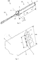
- FIG 1 shows a perspective view of a propeller 100 with two propeller blades 10 according to the invention seen from the suction side.
- the propeller blade 10 can be used for a propeller 100 rotating in a defined direction of rotation R about an axis of rotation 4, which propeller blade 10 has a pressure side 2, opposite thereto a suction side 3, it has a blade root 5 formed to be connectable to the propeller 100, it also has a blade tip 6 at its radially outer end, which is thus located along the orbit traveled by the propeller 100 during operation.
- the propeller 100 shown in the figure further comprises a propeller hub 20 in driving connection with the axis of rotation 4.
- the two opposed propeller blades 10 are connected to the hub 20 at their blade roots 5.
- propellers there are aircraft propellers in which the propeller blades 10 are generally made up in one piece so that its length is substantially equal to the diameter of the circle described by the propeller.
- the length of the blade Lb is understood as the distance between the blade root 5 and the blade tip 6.
- the propeller blade 10 has a leading edge 7 extending along the blade length Lb and a trailing edge 8 located opposite the leading edge 7.
- the first blade edge according to the direction of rotation indicated by the arrow R in Fig. 1 is the leading edge 7, while the subsequent blade edge is the trailing edge 8; the blade width between them is generally referred to as chord length.
- propeller blades we distinguish between the so-called “pointed” or “wide” blades.
- Propeller blades whose end or tip terminates at a point, namely at the intersection of the trailing edge 8 and the leading edge 7 of the propeller blade, are the pointed blades. In practice, naturally, these end points are rounded by some radius, for technical and strength reasons. If the end of the propeller blade is not clearly pointed, then the point of intersection of the longitudinal axis of the blade and the chord length at the blade end, i.e. the width Wb of the blade end (tip) is regarded as that point.
- the so-called "wide” blade tips do not end at a point, but the blade tips 6 have a measurable width Wb (chord length).
- the present invention preferably relates to such wide blade tips.
- the width of the blade tip Wb of the propeller blade 10 measured at the blade tip 6 is preferably at least one third of the width Wb 5 of the blade 10 measured at the blade root 5 (see Figure 6 ).
- the selection of the chord length of the propeller blade 10 causes a problem, and in the case of high power, wide blade tips 6 should be formed. This may be due to the fact that the diameter of the propeller 100 cannot be increased larger because it would hit the ground, so it is necessary to increase the width Wb of the blade tip 6. At this point, however, the losses from the flow around the blade tips 6 increase drastically.
- the invention uses the phenomenon of vortex interference to reduce or eliminate the potential loss derivable from the flow of the blade tips 6.
- the present invention uses a passive approach, i.e. no intervention or complicated control during operation is needed, but an efficient slot formation is applied near the blade tip 6.
- FIG. 7 shows how the air passing from the pressure side 2 to the suction side 3 at the blade tip 6 splits into two branches due to the slot 9, and the air branch passing through the slot 9 having a CV vortex of substantially the same magnitude but with a swirl in the opposite direction which reduces or extinguishes the harmful V-vortices generated at the blade tips 6.
- the harmful vortices are designated by V
- the counter-vortices extinguishing or reducing them, generated by the present invention are designated by CV.
- the slot 9 functions as a nozzle.
- the slot 9 is formed in the propeller blade 10 in a manner connecting the pressure side 2 with the suction side 3.
- the slot 9 has a length Ls and an inlet opening 9a with a predetermined width Wsp formed on the pressure side 2 ( Figs. 5 and 7 ), one side of which inlet opening is the brink DL max of the slot 9 farthest from the blade tip 6 ( Figs. 5 and 10a-10c ).
- the slot 9 also has an outlet opening 9b with a predetermined width Wss formed on the suction side 3 ( Figs.
- the slot 9 is formed in the vicinity of the blade tip 6, i.e. the distance between the slot brink DL max of the slot 9 farthest from the blade tip 6 and the blade tip 6 is at most one-eighth of the length Lb of the propeller blade 10, but its value preferably ranges from one tenth to one twentieth of the length Lb of the propeller blade 10.
- the inlet opening 9a of the slot 9 has a larger surface area than the outlet opening 9b thereof.
- overpressure is generated on the lower half of the propeller blade 10, i.e. on its pressure side 2.
- a portion of the medium here enters the slot 9 through the inlet opening 9a and then exits through the outlet opening 9b.
- the slot brink DL min of the slot 9 closest to the blade tip 6 is located in the outlet opening 9b, forming one side thereof ( Figure 3 ).
- the side 9c of the slot 9 farthest from the blade tip 6 is preferably curved from the pressure side 2 to the suction side 3, i.e. curved over its entire length, so that the slot 9 has an ever-narrowing design from the inlet opening 9a to the outlet opening 9b. This facilitates, on the one hand, the entry of the medium into the slot 9 and, on the other hand, further increases its pressure and speed.
- the side 9d of the slot 9 opposite the curved slot side 9c, closer to the blade tip 6, is substantially straight and perpendicular to the pressure side 2 almost on its entire length, starting from the inlet opening 9a, but near the outlet opening 9b a curved slot side 9e with a smaller radius than that of the curved slot side 9c is arranged on slot side 9d.
- the curved slot side 9e deflects the medium flowing out of the outlet opening 9b against the harmful vortex V at the blade tip 6.
- Figure 10a shows that the intersection of the slot side 9e and the suction side 3 gives the slot brink DL min which is located closest to the blade tip 6.
- the cross-section of the slot 9 could also be formed from straight sides ( Figure 10b ), according to which the side 9c is not curved but straight and inclined, connecting the inlet opening 9a with the outlet opening 9b of smaller area.
- side 9d can also be straight in its entire section from the pressure side 2 to the suction side 3, so it does not have a curved slot side 9e near the outlet opening 9b.
- the design of the side 9d may be substantially perpendicular to or at an angle to the pressure side 2 ( Fig. 10c ).
- the slot 9 is arranged substantially parallel to the circumference of the emerging harmful vortex V so that the intersection of the superficies (or surface) of the vortex V and the surface of the propeller blade 10 provides the location of the slot 9 to be formed.
- the detrimental vortex V is substantially frustoconical along the width Wb of the blade tip 6 ( Fig. 2 ), accordingly the slot 9 - i.e. its slot brink DL min - is arranged slightly oblique to the blade tip 6 along the width Wb of the blade tip 6.
- the distance of the slot 9 from the blade tip 6 is expressed by the distances measured from the two points of the slot 9, namely from its beginning towards the leading edge 7 and from its end towards the trailing edge 8 ( Fig. 3 ).
- Figure 2 shows a slot design where the slot 9 is continuous. However, for reasons of strength, the slot 9 is preferably divided into at least two slot-sections 9 1 ... 9 n along its length Ls by at least one partition wall 11 1 ... 11 n-1 .
- Figs. 3-6 and 8-9 respectively show slots 9, which are divided into two slot-sections 9 1 , 9 2 by a partition wall 11 1 .
- Figure 3 shows a first distance d1 measured between the slot brink DL min of the slot 9 and the blade tip 6 at the side of the slot 9 closest to the leading edge 7 and seen from the suction side 3; as well as a second distance d2 measured between the slot brink DL min of the slot 9 and the blade tip 6 at the side 9f of the slot 9 (see Fig. 8 ) closest to the trailing edge 8 and seen from the suction side 3.
- the distances d1 and d2 were determined by physical experiments, based on which the first distance d 1 of the slot 9 from the blade tip 6 is 9% -18,5%, preferably 13,8% of the width Wb of the blade tip 6; and the second distance d2 of the slot 9 from the blade tip 6 is 14% to 23,5%, preferably 18,8% of the width Wb of the blade tip 6.
- the geometry, size and location of the slot 9 described here ensure the creation of a counter-rotation CV in the opposite direction for damping or extinguishing the harmful V vortex.
- the length Ls of the slot 9 as well as the width Wsp therof formed on the pressure side 2 and the width Wss formed on the suction side 3 are characterized as follows ( Figures 3 and 5 ).
- the slot 9, divided into slot-sections 9 1 ... 9 n has n pieces of outlet openings 9b 1 ... 9b n on the suction side 3.
- the outlet openings 9b 1 ... 9b n are each rectangular, and the rectangle enclosing them is considered (for the sake of simplicity) to be the outlet opening 9b.
- the longer side of the rectangle delimiting the outlet opening 9b gives the length Ls of the slot 9.
- the shorter side of the enclosing rectangle of the outlet openings 9b 1 ... 9b n i.e. the width Wss formed on the suction side 3 of the slot 9, is a fraction thereof, approximately 2% -10%, preferably 3,53% of the length Ls of the slot 9.
- the slot 9, divided into slot-sections 9 1 ... 9 n has n pieces of inlet openings 9a 1 ... 9a n on the pressure side 2.
- the inlet openings 9a 1 ... 9a n are each rectangular, and the rectangle enclosing them is considered to be the inlet opening 9a.
- the length of the inlet opening 9a is equal to the length of the outlet opening 9b, which gives the length Ls of the slot 9.
- the shorter side of the enclosing rectangle of the inlet openings 9a 1 ... 9a n i.e. the rectangle delimiting the inlet opening 9a, that is, the width Wsp formed on the pressure side 2 of the slot 9 is smaller, approximately 20% -80%, preferably 50% of the length Ls of the slot 9.
- the length Ls of the slot 9, i.e. the longer extent of the side 9d, is approximately 50-90%, preferably 60%, of the width Wb of the blade tip 6, wherein according to one embodiment, the slot 9 is centrally arranged along the width Wb of the blade tip 6, i.e. is located at substantially the same distance from the leading edge 7 and the trailing edge 8. According to another embodiment, the distance of the slot 9 - i.e. the side 9f ( Fig. 8 ) - from the trailing edge 8 is approximately 0,1-5% of the width Wb of the blade tip 6.
- the extension of the curved slot side 9c parallel to the leading edge 7 and the trailing edge 8 ranges from 30% to 98% of the length Ls of the slot 9.
- the extent of the curved slot side 9e parallel to the leading edge 7 and the trailing edge 8 ranges from 0,1% to 2% of the length Ls of the slot 9.
- the slot 9 comprises pressure equalizing elements 12, 13, 14.
- the pressure equalizing element is an element 13, 14 which partially covers the inlet opening 9a of the slot 9.
- those parts of the slot 9 which can casuse measurable air resistance during the operation of the propeller blade 10, and thus causing further turbulence and pressure unevenness within the slot 9, are at least partially covered as can be seen on Figs. 9 and 10a-10c .
- the parts forming base for air resistance and pressure unevenness are the side 9f of the slot 9 (indicated in Fig.
- the inlet opening 9a of the slot 9 is covered with a plate 13 on approximately 10% -50% of its width Wsp, towards the blade tip 6, along the entire length Ls of the slot 9.
- the plate 13 can be fixed by gluing, welding, releasable bonding, e.g. by screwing.
- the material of the plate 13 can be made of wood, metal, plastic or a composite material.
- the inlet opening 9a of the slot 9 is preferably covered approximately 10% -50% of its width Wsp, filling the space 14 of the slot 9 towards the blade tip 6.
- the coverage is realized along the entire length Ls of the slot 9.
- the simplest way to fill the space 14 is to leave the own material of the propeller blade 10 as a filler.
- Covering the slot 9 with the aforementioned elements 13, 14 also restores the original contour (profile) of the cross-section of the blade 10 over the covered part, which original profile was formed taking into account the aerodynamic aspects in a way that the blade tip-vortex reducing ability of the slot 9 remains maintained.
- the pressure equalizing element is designed as a pressure equalizing channel 12 arranged in the partition walls 10 1 ...10 n-1 , which alleviates the losses due to pressure dissonances prevalent at a divided slot 9.
- a divided slot 9 another cause for the pressure differences in each slot-section 9 1 ... 9 n is that the pressure in the lower half of the propeller blade 10, i.e. on the pressure side 2, does not have a constant value, it changes along the width of the blade.
- the lower airflow of the propeller blade 10, which has a higher air pressure during operation, is halved on the pressure side 2 of the propeller blade 10 as it passes through the slot 9.
- the pressure dissonances (irregularities) existing right before passing are compensated for as the air pass through the slot 9 due to the deflection effect caused by the slot 9.
- the pressure-equalizing effect of the channels 12 formed in the partition walls 10 1 ...10 n-1 can be detected in the case of uncovered slots 9 as well, so it can be used for the blade tip pressure equalization by the present invention alternatively or additionally to the slot-covering approach.
- each of the slot-sections 9 1 ...9 n is preferably etched out of an originally contiguous propeller blade 10 in order to ensure the continuity of the material of the propeller blade 10, thereby increasing the strenght of the propeller blade 10 and the blade tip 6.
- a propeller 100 for use in aircrafts, helicopters, fans and drones as well as wind turbines with horizontal axis, the propeller 100 being adapted to rotate in a defined direction of rotation R about an axis of rotation 4; the propeller 100 having at least one propeller blade, wherein the propeller blade is attached to a propeller hub 20 drivingly connected to the axis of rotation 4, and the at least one propeller blade 10 is a propeller blade according to the first aspect of the invention.
- the propeller 100 comprises at least two propeller blades 10 according to the first aspect of the invention, attached to the propeller hub 20, wherein the at least two propeller blades 10 are integrally formed in one piece. This is especially relevant for propeller blades designed with 3D printing technology.
- the propeller 100 preferably comprises at least two propeller blades 10 according to the first aspect of the invention, attached to the propeller hub 20, wherein the at least two propeller blades 10 and the propeller hub 20 are integrally formed in one piece. This feature is especially relevant for the production of propellers designed with 3D printing technology.
- the solution according to the invention can be applied for propeller blades 10 of any size and for propellers 100 provided therewith.
- the propeller blade 10 can be made of wood, metal or plastic, or a composite material.
- the blade tip slot 9 is formed in one or more at least partly covered sections and / or with pressure equalizing channels according to the present invention, the vibrations generated at the tip of the propeller blade 10 are reduced, and the service life of the blades is considerably increased.
Landscapes
- Engineering & Computer Science (AREA)
- Mechanical Engineering (AREA)
- General Engineering & Computer Science (AREA)
- Aviation & Aerospace Engineering (AREA)
- Physics & Mathematics (AREA)
- Fluid Mechanics (AREA)
- Manufacturing & Machinery (AREA)
- Chemical & Material Sciences (AREA)
- Materials Engineering (AREA)
- Life Sciences & Earth Sciences (AREA)
- Sustainable Development (AREA)
- Sustainable Energy (AREA)
- Combustion & Propulsion (AREA)
- Structures Of Non-Positive Displacement Pumps (AREA)
Abstract
Description
- The present invention relates to a propeller for aircrafts, helicopters, wind turbines with horizontal axis, fans and drones, it also relates to a wide propeller blade.
- The requirements of propellers and the propeller blades that are part of them are very complex. The ideal flow conditions should be approximated as closely as possible so that the power absorbed or transmitted is equal to the power of the connected motor or generator. This can always be solved only at the cost of a technical compromise.
- If propellers, wind turbines with horizontal axis or fans can only be made with a limited diameter, the desired performance can be achieved by increasing the width of their blades. In this case, however, the flow conditions deteriorate and significant, undesirable vortices are generated at the wide tip of the blades. These obviously cause energy loss and efficiency degradation. An alternative or additional solution could be to increase the number of blades, but in the case of more than four blades arranged in one plane, the blades interfere with each other from a flow point of view.
- In the case of aircraft wings, for reducing losses, the so-called wing flap or wingtip device, also known as a winglet can be used, which is a vertically positioned auxiliary wing flap or an upward extension of the wing located at the wing tips of some airplanes. The winglet reduces air vortices at the wing tip, which would otherwise significantly increase the air resistance of the wing of the aircraft. However, the winglet can only be used effectively in linear motion, therefore it is generally used on wings.
- Propeller blades used at aircrafts, helicopters or drones, as well as wind turbine blades of horizontal axis of rotation or fan blades also generate air vortices at the distal ends of the axis of rotation, which increase energy losses. The losses are particularly high if the tip of the blades are not taperingly pointed but wide.
- A vortex distribution plate placed at the end (tip) of wings or blades, similar to a winglet, is shown in document
DE3816430 . The plate is arranged perpendicular to the longitudinal direction of the blade and is provided with holes to reduce the vortices at the the blade tip. The holes widen towards the outer edge of the plate, thus ensuring that the pressure difference between the pressure and suction side does not suddenly begin to equalize in order to maintain the buoyancy. - The solution described in patent application
EP 0782956 A1 for helicopter rotors attempts to reduce the vortices generated at the tip of the helicopter rotor by the complex geometry of the rotor end. -
US 2,160,323 discloses a propeller having a passage in the blade to reduce vacuum emerging on the suction side of the blade as well as the deriving noise and to increase efficiency. The passage connecting the pressure side of the blade to the suction side is elongated, the length of which is 70-80% that of the blade and is arranged substantially along the longitudinal axis of the blade. This patent document, however, does not specifically teach how to reduce flow losses at the blade tip. -
U.S. patent document 6,283,406 B1 discloses a noise reduction method for the noise generated by a helicopter rotor. At the blade tips, inlets close to the leading edge and outlets close to the trailing edge, as well as passages connecting them are arranged near the surface of both the suction and the pressure sides. Thus, the passages do not connect the suction and pressure sides, but run substantially parallel to the sides of the blade and form slots that are not permanently permeable to air, but are controlled to open and close above a certain level of noise, pressure and speed. According to another aspect of this solution, outlet openings are arranged at the blade tips in several places and directions, through which gas jets are led to accelerate the damping of the vortices at the blade tips. -
US 5,791,875 also teaches a relatively complex control device for reducing blade tip vortices. Here, a vortex rotating in the opposite direction is created, and the medium for this purpose is guided to the wing tips in channels arranged in the wing, and in the rotor blade, where the medium is driven out with controlled pressure and in a controlled, curved path to form a counter-vortex. - The solution described in the published
EP3509945 A1 document can be considered as the closest piece of prior art, wherein the slots connecting the suction and the pressure sides are formed at the blade tips, specifically in order to eliminate the losses at the blade tips. The distance of the slot from the blade tip is given as a percentage of the length of the diameter, adapted to the size and location of the vortex cones formed at the blade tip, for extinguishing them by vortex interference. The slot is divided into sections with small interruptions. - The disadvantage of the prior art wings and propellers is that they do not provide a solution to also ensure the maximum strength of the blade or the blade tip when designing a device for eliminating, reducing or stopping the vortices at the blade tip (or wing tip). Each of the referenced inventions has been created by material reliefs, omissions such as longitudinal gaps, holes, passages formed inside the blade, sometimes by also placing complex control elements which mean additional loads; however, there is no mention of strength aspects. Furthermore, they do not teach how to eliminate losses specifically due to pressure irregularities.
- It is an object of the present invention to reduce or eliminate flow losses at the blade tip by providing a propeller blade or propeller that provides uniform flow conditions along the entire width of the blade tip.
- It is a further object that the structure of the propeller blade or the propeller designed to reduce or eliminate flow losses at the blade tip should provide minimal air resistance and be of adequate strength to withstand centrifugal force.
- In addition, it is an important criterion of the invention to provide a simple, maintenance-free or low-maintenance solution.
- According to a first aspect of the invention, the object is achieved by providing a propeller blade applicable for a propeller for aircrafts, helicopters, wind turbines with horizontal axis, fans and drones, the propeller rotating in a determined rotational direction about an axis of rotation; wherein the propeller blade, has a pressure side, a suction side opposite thereto, a blade root adapted to be connected to the propeller, a blade tip at the opposite end with respect to the blade root; wherein a slot is formed within the propeller blade connecting the pressure side with the suction side, which slot has an inlet opening formed on the pressure side and an outlet opening formed on the suction side, and the slot contains a pressure equalizing element.
- According to a second aspect of the invention, our object is achieved by providing a propeller for aircrafts, helicopters, wind turbines with horizontal axis, fans and drones, which propeller is adapted to rotate in a certain direction of rotation about an axis of rotation; the propeller having at least one propeller blade, wherein the propeller blade is fixed to a propeller hub which is drivingly connected to the axis, and the at least one propeller blade is a propeller blade according to the first aspect of the invention.
- The invention will now be described in more detail with reference to the accompanying drawing. In the drawing
-
Figure 1 is a perspective view of a propeller with two propeller blades according to the invention seen from the suction side, -
Figure 2 shows the tip of the propeller blades shown inFigure 1 , with a continuous blade tip slot, marking the harmful vortex cone at the blade tip, -
Figure 3 shows the tip of a propeller blade according to the invention seen from the suction side, with a blade tip slot divided into two slot-sections, -
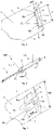
Figure 4 is a perspective view a prior art propeller with two propeller blades, seen from the pressure side; -
Figure 5 shows the tip of the propeller blades shown inFigure 4 , with the blade tip slot divided into two slot-sections, -
Figure 6 is a bottom view of a prior art propeller with two propeller blades; -
Figure 7 is a cross-sectional view of the tip of the propeller blade taken along line A-A ofFigure 6 with the harmful vortices and the ones extinguishing them; -
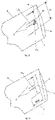
Figure 8 shows a preferred embodiment of the tip of a propeller blade according to the invention seen from the pressure side, with a slot divided into two slot-sections and a pressure equalizing channel formed therebetween, in the uncovered state, -
Figure 9 shows a preferred embodiment of the tip of a propeller blade according to the invention seen from the pressure side, with a slot divided into two slot-sections in a state covered with a plate, -
Figure 10a is a cross-sectional view of an arcuate embodiment of a blade tip slot according to the invention, wherein the inlet opening is covered with a plate over a portion of its width, -
Figure 10b is a cross-sectional view of a straight sidewall embodiment of a blade tip slot according to the invention, wherein the inlet opening is covered with a plate over a portion of its width; -
Figure 10c is a cross-sectional view of a straight sidewall embodiment of a blade tip slot according to the invention, wherein the inlet opening is covered over a portion of its width, with the portion of the slot close to the blade tip filled. - A first aspect of the present invention relates to propeller blades. The general characteristics of the
propeller blades 10 for the flowing of gaseous media in the case of airplanes, helicopters, fans or drones and for the extraction of energy in the case of wind turbines with a horizontal axis of rotation are shown by means ofFigures 1 and 2 . -
Figure 1 shows a perspective view of apropeller 100 with twopropeller blades 10 according to the invention seen from the suction side. Thepropeller blade 10 can be used for apropeller 100 rotating in a defined direction of rotation R about an axis ofrotation 4, whichpropeller blade 10 has apressure side 2, opposite thereto asuction side 3, it has ablade root 5 formed to be connectable to thepropeller 100, it also has ablade tip 6 at its radially outer end, which is thus located along the orbit traveled by thepropeller 100 during operation. Thepropeller 100 shown in the figure further comprises apropeller hub 20 in driving connection with the axis ofrotation 4. The two opposedpropeller blades 10 are connected to thehub 20 at theirblade roots 5. - There are aircraft propellers in which the
propeller blades 10 are generally made up in one piece so that its length is substantially equal to the diameter of the circle described by the propeller. However, since in the case of wind turbines or fans, it is more common to mountseparate propeller blades 10 on the propeller hub andfan hub 20, the length of which is thus approximately the radius of said circle reduced by the radius of the hub. In this application the length of the blade Lb is understood as the distance between theblade root 5 and theblade tip 6. - The
propeller blade 10 has a leadingedge 7 extending along the blade length Lb and atrailing edge 8 located opposite the leadingedge 7. When thepropeller blade 10 is mounted on thepropeller 100, during rotation, the first blade edge according to the direction of rotation indicated by the arrow R inFig. 1 is the leadingedge 7, while the subsequent blade edge is thetrailing edge 8; the blade width between them is generally referred to as chord length. - Among propeller blades we distinguish between the so-called "pointed" or "wide" blades. Propeller blades whose end or tip terminates at a point, namely at the intersection of the
trailing edge 8 and the leadingedge 7 of the propeller blade, are the pointed blades. In practice, naturally, these end points are rounded by some radius, for technical and strength reasons. If the end of the propeller blade is not clearly pointed, then the point of intersection of the longitudinal axis of the blade and the chord length at the blade end, i.e. the width Wb of the blade end (tip) is regarded as that point. The so-called "wide" blade tips do not end at a point, but theblade tips 6 have a measurable width Wb (chord length). The present invention preferably relates to such wide blade tips. The width of the blade tip Wb of thepropeller blade 10 measured at theblade tip 6 is preferably at least one third of the width Wb 5 of theblade 10 measured at the blade root 5 (seeFigure 6 ). - In the case of high power adaptation, the selection of the chord length of the
propeller blade 10 causes a problem, and in the case of high power,wide blade tips 6 should be formed. This may be due to the fact that the diameter of thepropeller 100 cannot be increased larger because it would hit the ground, so it is necessary to increase the width Wb of theblade tip 6. At this point, however, the losses from the flow around theblade tips 6 increase drastically. Whenwide blade tips 6 are used, the invention uses the phenomenon of vortex interference to reduce or eliminate the potential loss derivable from the flow of theblade tips 6. The present invention uses a passive approach, i.e. no intervention or complicated control during operation is needed, but an efficient slot formation is applied near theblade tip 6. - The mathematical modeling of the cone-shaped harmful V-vortices at the 6 blade tips illustrated in
Figure 2 is a rather complex task, a serious computational arsenal, and a number of approximations and simplifications would have to be applied. [Goldstein, Sydney. (1929). On the Vortex Theory of Screw Propeller.] The loss, efficiency-reduction derivable from the V-vortices at theblade tip 6 is more easily computable. Accordingly, the geometry and location of theslot 9 were determined on the basis of empirical measurement data, with iterational steps. - The cross-sectional view of
Fig. 7 shows how the air passing from thepressure side 2 to thesuction side 3 at theblade tip 6 splits into two branches due to theslot 9, and the air branch passing through theslot 9 having a CV vortex of substantially the same magnitude but with a swirl in the opposite direction which reduces or extinguishes the harmful V-vortices generated at theblade tips 6. InFigures 2 and7 , the harmful vortices are designated by V, and the counter-vortices extinguishing or reducing them, generated by the present invention are designated by CV. - In order to achieve the best possible efficiency, it is important to determine the exact dimensions, geometry and arrangement of the
slot 9. InFigs. 7 and10a-10c , it can be clearly seen that theslot 9 functions as a nozzle. Theslot 9 is formed in thepropeller blade 10 in a manner connecting thepressure side 2 with thesuction side 3. Theslot 9 has a length Ls and aninlet opening 9a with a predetermined width Wsp formed on the pressure side 2 (Figs. 5 and7 ), one side of which inlet opening is the brink DL max of theslot 9 farthest from the blade tip 6 (Figs. 5 and10a-10c ). Theslot 9 also has anoutlet opening 9b with a predetermined width Wss formed on the suction side 3 (Figs. 3 and7 ). Theslot 9 is formed in the vicinity of theblade tip 6, i.e. the distance between the slot brink DLmax of theslot 9 farthest from theblade tip 6 and theblade tip 6 is at most one-eighth of the length Lb of thepropeller blade 10, but its value preferably ranges from one tenth to one twentieth of the length Lb of thepropeller blade 10. - The
inlet opening 9a of theslot 9 has a larger surface area than the outlet opening 9b thereof. During operation, overpressure is generated on the lower half of thepropeller blade 10, i.e. on itspressure side 2. A portion of the medium here enters theslot 9 through theinlet opening 9a and then exits through theoutlet opening 9b. The slot brink DLmin of theslot 9 closest to theblade tip 6 is located in theoutlet opening 9b, forming one side thereof (Figure 3 ). - The
side 9c of theslot 9 farthest from theblade tip 6 is preferably curved from thepressure side 2 to thesuction side 3, i.e. curved over its entire length, so that theslot 9 has an ever-narrowing design from the inlet opening 9a to theoutlet opening 9b. This facilitates, on the one hand, the entry of the medium into theslot 9 and, on the other hand, further increases its pressure and speed. Theside 9d of theslot 9 opposite thecurved slot side 9c, closer to theblade tip 6, is substantially straight and perpendicular to thepressure side 2 almost on its entire length, starting from theinlet opening 9a, but near theoutlet opening 9b acurved slot side 9e with a smaller radius than that of thecurved slot side 9c is arranged onslot side 9d. Thecurved slot side 9e deflects the medium flowing out of theoutlet opening 9b against the harmful vortex V at theblade tip 6.Figure 10a . shows that the intersection of theslot side 9e and thesuction side 3 gives the slot brink DLmin which is located closest to theblade tip 6. - Instead of the curved slot design shown in
Figs 7 and10a , the cross-section of theslot 9 could also be formed from straight sides (Figure 10b ), according to which theside 9c is not curved but straight and inclined, connecting theinlet opening 9a with the outlet opening 9b of smaller area. Furthermore,side 9d can also be straight in its entire section from thepressure side 2 to thesuction side 3, so it does not have acurved slot side 9e near theoutlet opening 9b. The design of theside 9d may be substantially perpendicular to or at an angle to the pressure side 2 (Fig. 10c ). By the latter inclined arrangement of theslot side 9d, substantially the entire part of thespace 14 of theslot 9 is filled, therefore also providing a kind of (solid) partial covering of theinlet opening 9a. - The
slot 9 is arranged substantially parallel to the circumference of the emerging harmful vortex V so that the intersection of the superficies (or surface) of the vortex V and the surface of thepropeller blade 10 provides the location of theslot 9 to be formed. The detrimental vortex V is substantially frustoconical along the width Wb of the blade tip 6 (Fig. 2 ), accordingly the slot 9 - i.e. its slot brink DLmin - is arranged slightly oblique to theblade tip 6 along the width Wb of theblade tip 6. Thus, the distance of theslot 9 from theblade tip 6 is expressed by the distances measured from the two points of theslot 9, namely from its beginning towards the leadingedge 7 and from its end towards the trailing edge 8 (Fig. 3 ). -
Figure 2 shows a slot design where theslot 9 is continuous. However, for reasons of strength, theslot 9 is preferably divided into at least two slot-sections 91... 9n along its length Ls by at least one partition wall 111... 11n-1.Figs. 3-6 and8-9 , respectively showslots 9, which are divided into two slot-sections blades 10, theslot 9 must be divided into either n = 3 or even more parts so that the end piece of theblade tip 6 cannot be torn off by the centrifugal force or by the air forces prevailing at the flight altitude. -
Figure 3 shows a first distance d1 measured between the slot brink DL min of theslot 9 and theblade tip 6 at the side of theslot 9 closest to theleading edge 7 and seen from thesuction side 3; as well as a second distance d2 measured between the slot brink DL min of theslot 9 and theblade tip 6 at theside 9f of the slot 9 (seeFig. 8 ) closest to the trailingedge 8 and seen from thesuction side 3. The distances d1 and d2 were determined by physical experiments, based on which the first distance d 1 of theslot 9 from theblade tip 6 is 9% -18,5%, preferably 13,8% of the width Wb of theblade tip 6; and the second distance d2 of theslot 9 from theblade tip 6 is 14% to 23,5%, preferably 18,8% of the width Wb of theblade tip 6. The geometry, size and location of theslot 9 described here ensure the creation of a counter-rotation CV in the opposite direction for damping or extinguishing the harmful V vortex. - Experience has shown that the generated counter-vortices CV follow the changes in the slot distances d1, d2 more sensitively if they are a function of the width Wb of the
blade tip 6, rather than if they were a function of the diameter of thepropeller 100. Therefore, giving a change in the slot distance relative to theblade tip 6 gives a significantly more accurate result than what was disclosed inEP3509945 A1 , where the corresponding distance values of theslot 9 from theblade tip 6 are given as a percentage of the length of the diameter of thepropeller 100. - The length Ls of the
slot 9 as well as the width Wsp therof formed on thepressure side 2 and the width Wss formed on thesuction side 3 are characterized as follows (Figures 3 and 5 ). - The
slot 9, divided into slot-sections 91... 9n, has n pieces ofoutlet openings 9b1... 9bn on thesuction side 3. Theoutlet openings 9b1... 9bn are each rectangular, and the rectangle enclosing them is considered (for the sake of simplicity) to be theoutlet opening 9b. The longer side of the rectangle delimiting theoutlet opening 9b gives the length Ls of theslot 9. The shorter side of the enclosing rectangle of theoutlet openings 9b1... 9bn, i.e. the width Wss formed on thesuction side 3 of theslot 9, is a fraction thereof, approximately 2% -10%, preferably 3,53% of the length Ls of theslot 9. - The
slot 9, divided into slot-sections 91... 9n, has n pieces ofinlet openings 9a1... 9an on thepressure side 2. Theinlet openings 9a1... 9an are each rectangular, and the rectangle enclosing them is considered to be theinlet opening 9a. The length of theinlet opening 9a is equal to the length of theoutlet opening 9b, which gives the length Ls of theslot 9. The shorter side of the enclosing rectangle of theinlet openings 9a1... 9an, i.e. the rectangle delimiting theinlet opening 9a, that is, the width Wsp formed on thepressure side 2 of theslot 9 is smaller, approximately 20% -80%, preferably 50% of the length Ls of theslot 9. - The length Ls of the
slot 9, i.e. the longer extent of theside 9d, is approximately 50-90%, preferably 60%, of the width Wb of theblade tip 6, wherein according to one embodiment, theslot 9 is centrally arranged along the width Wb of theblade tip 6, i.e. is located at substantially the same distance from theleading edge 7 and the trailingedge 8. According to another embodiment, the distance of the slot 9 - i.e. theside 9f (Fig. 8 ) - from the trailingedge 8 is approximately 0,1-5% of the width Wb of theblade tip 6. - The extension of the
curved slot side 9c parallel to theleading edge 7 and the trailingedge 8 ranges from 30% to 98% of the length Ls of theslot 9. The extent of thecurved slot side 9e parallel to theleading edge 7 and the trailingedge 8 ranges from 0,1% to 2% of the length Ls of theslot 9. - The development realized by the present invention is based on the equalization of the pressure differences occurring at the
blade tip 6 and in the vicinity of theslot 9, as well as on its flow-improving effect. Accordingly, theslot 9 comprisespressure equalizing elements - According to a preferred embodiment, the pressure equalizing element is an
element slot 9. In order to increase the efficiency, those parts of theslot 9 which can casuse measurable air resistance during the operation of thepropeller blade 10, and thus causing further turbulence and pressure unevenness within theslot 9, are at least partially covered as can be seen onFigs. 9 and10a-10c . The parts forming base for air resistance and pressure unevenness are theside 9f of the slot 9 (indicated inFig. 8 ) closest to the trailingedge 8, which is perpendicular to the rotational speed vector; also in the case of a dividedslot 9, surfaces 111f...11(n-1)f of the partition walls 111...11n-1, which are perpendicular to the rotational speed vector seen from theinlet opening 9a (only one partition wall 111 is illustrated inFig. 8 , accordingly, only one such affected surface 111f is shown). - Hence, in order to achieve a reduction in air resistance and to equalize pressure, a part of the inlet opening 9a of the
slot 9, which is closer to theblade tip 6 is covered by theelements slot 9 along the entire length Ls thereof. - Preferably, the inlet opening 9a of the
slot 9 is covered with aplate 13 on approximately 10% -50% of its width Wsp, towards theblade tip 6, along the entire length Ls of theslot 9. Theplate 13 can be fixed by gluing, welding, releasable bonding, e.g. by screwing. The material of theplate 13 can be made of wood, metal, plastic or a composite material. - As an alternative solution shown in
Fig. 10c , the inlet opening 9a of theslot 9 is preferably covered approximately 10% -50% of its width Wsp, filling thespace 14 of theslot 9 towards theblade tip 6. The coverage is realized along the entire length Ls of theslot 9. The simplest way to fill thespace 14 is to leave the own material of thepropeller blade 10 as a filler. - Covering the
slot 9 with theaforementioned elements blade 10 over the covered part, which original profile was formed taking into account the aerodynamic aspects in a way that the blade tip-vortex reducing ability of theslot 9 remains maintained. - In the case of
slots 9 which, for considerations of strength, are divided by partition walls 111...11n-1 separating them along the length Ls, the cover has an additional function-improving effect. For, in the uncovered state, in each of the slot-sections 91... 9n, as in separate chambers, the pressure differences develop deriving from turbulence. However, due to the coverage, the resulting pressure differences are reduced. - According to another preferred embodiment, the pressure equalizing element is designed as a
pressure equalizing channel 12 arranged in thepartition walls 101...10n-1, which alleviates the losses due to pressure dissonances prevalent at a dividedslot 9. For, in the case of a dividedslot 9, another cause for the pressure differences in each slot-section 91... 9n is that the pressure in the lower half of thepropeller blade 10, i.e. on thepressure side 2, does not have a constant value, it changes along the width of the blade. The lower airflow of thepropeller blade 10, which has a higher air pressure during operation, is halved on thepressure side 2 of thepropeller blade 10 as it passes through theslot 9. The pressure dissonances (irregularities) existing right before passing are compensated for as the air pass through theslot 9 due to the deflection effect caused by theslot 9. - In the case of a divided
slot 9, however, the pressure irregularities would only be equalized within each slot-section 91...9n (chambers). Due to the pressure differences, the pressure required to create the nozzle effect may therefore be diverse in the individual chambers. This would create counter-vortices CV with different spin values for eachchamber 91...9n (slot-section), so apressure equalizing channel 12 is preferably formed on thepartition walls 101...10n-1 connecting theadjacent slot sections 91... 9n. - As a result, all
sections 91... 9n of theslot 9 can generate the same nozzle effect with the same pressure and the same impulse torque (spin), which is able to extinguish the harmful blade tip-vortex V, since that is not physically divided into sections. - The pressure-equalizing effect of the
channels 12 formed in thepartition walls 101...10n-1 can be detected in the case ofuncovered slots 9 as well, so it can be used for the blade tip pressure equalization by the present invention alternatively or additionally to the slot-covering approach. - To create the
slot 9, each of the slot-sections 91...9n is preferably etched out of an originallycontiguous propeller blade 10 in order to ensure the continuity of the material of thepropeller blade 10, thereby increasing the strenght of thepropeller blade 10 and theblade tip 6. - According to another aspect of the invention, there is provided a
propeller 100 for use in aircrafts, helicopters, fans and drones as well as wind turbines with horizontal axis, thepropeller 100 being adapted to rotate in a defined direction of rotation R about an axis ofrotation 4; thepropeller 100 having at least one propeller blade, wherein the propeller blade is attached to apropeller hub 20 drivingly connected to the axis ofrotation 4, and the at least onepropeller blade 10 is a propeller blade according to the first aspect of the invention. - Preferably, the
propeller 100 comprises at least twopropeller blades 10 according to the first aspect of the invention, attached to thepropeller hub 20, wherein the at least twopropeller blades 10 are integrally formed in one piece. This is especially relevant for propeller blades designed with 3D printing technology. - The
propeller 100 preferably comprises at least twopropeller blades 10 according to the first aspect of the invention, attached to thepropeller hub 20, wherein the at least twopropeller blades 10 and thepropeller hub 20 are integrally formed in one piece. This feature is especially relevant for the production of propellers designed with 3D printing technology. - The solution according to the invention can be applied for
propeller blades 10 of any size and forpropellers 100 provided therewith. Thepropeller blade 10 can be made of wood, metal or plastic, or a composite material. When theblade tip slot 9 is formed in one or more at least partly covered sections and / or with pressure equalizing channels according to the present invention, the vibrations generated at the tip of thepropeller blade 10 are reduced, and the service life of the blades is considerably increased.
Claims (9)
- Propeller blade (10), having a pressure side (2), a suction side (3) opposite the pressure side (3), a blade root (5) adapted to be connected to a propeller (100), a blade tip (6) at the opposite end with respect to the blade root (5), wherein a slot (9) is formed within the propeller blade (10) connecting the pressure side (2) with the suction side (3), which slot (9) has an inlet opening (9a) formed on the pressure side (2) and an outlet opening (9b) formed on the suction side (9b), characterized in that the slot (9) contains a pressure equalizing element (12, 13).
- Propeller blade (10) according to claim 1, characterized in that the slot (9) is divided into at least two slot-sections (91...9n) along its length (Ls) by at least one partition wall (111...11n-1).
- Propeller blade (10) according to claim 1, characterized in that the pressure equalizing element (13) is an element (13) partly covering the inlet opening (9a) of the slot (9).
- Propeller blade (10) according to claim 2, characterized in that the pressure equalizing element (13) is an element (13) partly covering the inlet opening (9a) of the slot (9).
- Propeller blade (10) according to claim 2 or 4, characterized in that the pressure equalizing element (13) is a channel (12) connecting the neighboring slot-sections (91...9n), the channel (12) being formed in the at least one partition wall (111...11n-1).
- Propeller blade (10) according to any one of the preceding claims, characterized in that the propeller blade (10) along its length (Lb) has a leading edge (7) and a trailing edge (8) opposite thereto; a first distance (d1) between a slot brink (DLmin) of the slot (9) located closest to the blade tip (6) and the blade tip (6) which distance (d1) is closest to the leading edge (7) is 9%-18,5% of the width of the blade tip (Wb), while a second distance (d2) between the slot brink (DLmin) of the slot (9) located closest to the blade tip (6) and the blade tip (6) which distance (d2) is closest to the trailing edge (8) is 14%-23,5% of the width of the blade tip (Wb).
- Propeller (100) adapted to rotate around a rotational axis (4) in a determined rotational direction (R), the propeller (100) has at least one propeller blade, wherein the propeller blade is fixed to a propeller hub (20) which is drivingly connected to the axis (4), characterized in that the at least one propeller blade is a propeller blade (10) according to any one of the preceding claims.
- Propeller (100) according to claim 7, characterized in that it contains at least two propeller blades (10) according to any one of claims 1-6 fixed to the propeller hub (20), wherein the at least two propeller blades (10) are formed integrally with one another from one piece.
- Propeller (100) according to claim 7, characterized in that it contains at least two propeller blades (10) according to any one of claims 1-6 fixed to the propeller hub (20), wherein the at least two propeller blades (10) and the propeller hub (20) are formed integrally with one another from one piece.
Applications Claiming Priority (1)
| Application Number | Priority Date | Filing Date | Title |
|---|---|---|---|
| HUP2000339A HU231494B1 (en) | 2020-10-14 | 2020-10-14 | Propeller and wide propeller blade |
Publications (2)
| Publication Number | Publication Date |
|---|---|
| EP3984882A1 true EP3984882A1 (en) | 2022-04-20 |
| EP3984882B1 EP3984882B1 (en) | 2024-03-20 |
Family
ID=89898813
Family Applications (1)
| Application Number | Title | Priority Date | Filing Date |
|---|---|---|---|
| EP21172864.7A Active EP3984882B1 (en) | 2020-10-14 | 2021-05-07 | Propeller and propeller blade |
Country Status (4)
| Country | Link |
|---|---|
| EP (1) | EP3984882B1 (en) |
| DK (1) | DK3984882T3 (en) |
| ES (1) | ES2982099T3 (en) |
| HU (1) | HU231494B1 (en) |
Citations (11)
| Publication number | Priority date | Publication date | Assignee | Title |
|---|---|---|---|---|
| US2160323A (en) | 1937-06-15 | 1939-05-30 | Tracy B Barnett | Propeller |
| US4478380A (en) * | 1982-12-03 | 1984-10-23 | Frakes James F | Wing tip vortices suppressor |
| DE3816430A1 (en) | 1988-05-13 | 1989-11-16 | Otilio Nemec | Edge vortex scatter plate for blade tips of aerodynamic and hydrodynamic wings and control surfaces |
| EP0782956A1 (en) | 1996-01-04 | 1997-07-09 | Gkn Westland Helicopters Limited | Aerofoil |
| US5791875A (en) | 1996-09-10 | 1998-08-11 | Mcdonnell Douglas Helicopter Co. | Tip vortex reduction system |
| US6283406B1 (en) | 1999-09-10 | 2001-09-04 | Gte Service Corporation | Use of flow injection and extraction to control blade vortex interaction and high speed impulsive noise in helicopters |
| EP1577212A2 (en) * | 2004-03-16 | 2005-09-21 | Westland Helicopters Limited | Improvements in or relating to aerofoils |
| WO2009098442A2 (en) * | 2008-02-04 | 2009-08-13 | Wingtec Holdings Limited | Wing control devices |
| US20170218774A1 (en) * | 2016-01-29 | 2017-08-03 | Rolls-Royce Corporation | Airfoils for reducing secondary flow losses in gas turbine engines |
| AU2018101230B4 (en) * | 2018-08-24 | 2019-05-02 | Círus, Norbert MR | Aerodynamic Regulation of Airscrew-, Fan- and Wind Turbine Blades with Bores and/or Cutting and/or Notching |
| EP3509945A1 (en) | 2016-09-07 | 2019-07-17 | Nyíri, Attila | Aerodynamic regulation of airscrew-, fan- and wind turbine blades with bores and/or cutting and/or notching |
-
2020
- 2020-10-14 HU HUP2000339A patent/HU231494B1/en unknown
-
2021
- 2021-05-07 ES ES21172864T patent/ES2982099T3/en active Active
- 2021-05-07 EP EP21172864.7A patent/EP3984882B1/en active Active
- 2021-05-07 DK DK21172864.7T patent/DK3984882T3/en active
Patent Citations (11)
| Publication number | Priority date | Publication date | Assignee | Title |
|---|---|---|---|---|
| US2160323A (en) | 1937-06-15 | 1939-05-30 | Tracy B Barnett | Propeller |
| US4478380A (en) * | 1982-12-03 | 1984-10-23 | Frakes James F | Wing tip vortices suppressor |
| DE3816430A1 (en) | 1988-05-13 | 1989-11-16 | Otilio Nemec | Edge vortex scatter plate for blade tips of aerodynamic and hydrodynamic wings and control surfaces |
| EP0782956A1 (en) | 1996-01-04 | 1997-07-09 | Gkn Westland Helicopters Limited | Aerofoil |
| US5791875A (en) | 1996-09-10 | 1998-08-11 | Mcdonnell Douglas Helicopter Co. | Tip vortex reduction system |
| US6283406B1 (en) | 1999-09-10 | 2001-09-04 | Gte Service Corporation | Use of flow injection and extraction to control blade vortex interaction and high speed impulsive noise in helicopters |
| EP1577212A2 (en) * | 2004-03-16 | 2005-09-21 | Westland Helicopters Limited | Improvements in or relating to aerofoils |
| WO2009098442A2 (en) * | 2008-02-04 | 2009-08-13 | Wingtec Holdings Limited | Wing control devices |
| US20170218774A1 (en) * | 2016-01-29 | 2017-08-03 | Rolls-Royce Corporation | Airfoils for reducing secondary flow losses in gas turbine engines |
| EP3509945A1 (en) | 2016-09-07 | 2019-07-17 | Nyíri, Attila | Aerodynamic regulation of airscrew-, fan- and wind turbine blades with bores and/or cutting and/or notching |
| AU2018101230B4 (en) * | 2018-08-24 | 2019-05-02 | Círus, Norbert MR | Aerodynamic Regulation of Airscrew-, Fan- and Wind Turbine Blades with Bores and/or Cutting and/or Notching |
Also Published As
| Publication number | Publication date |
|---|---|
| ES2982099T3 (en) | 2024-10-14 |
| HUP2000339A1 (en) | 2022-04-28 |
| EP3984882B1 (en) | 2024-03-20 |
| HU231494B1 (en) | 2024-04-28 |
| DK3984882T3 (en) | 2024-06-24 |
Similar Documents
| Publication | Publication Date | Title |
|---|---|---|
| US11987352B2 (en) | Fluid systems that include a co-flow jet | |
| EP2631175B1 (en) | Adaptive rotor blade | |
| CN104477380B (en) | Blade for a helicopter anti-torque device | |
| EP2316729B1 (en) | An element for generating a fluid dynamic force | |
| EP0918686B1 (en) | Improvements in or relating to fluid dynamic lift generation | |
| US7134631B2 (en) | Vorticity cancellation at trailing edge for induced drag elimination | |
| US7637462B2 (en) | Surface flow diverting and static charging ducted pores on wing or blade tip to reduce wake and BVI noise | |
| CN104040173B (en) | Turbine blade and system with forward blowing slots | |
| CN105314096B (en) | Individual gas sources supply without rudder face aircraft | |
| KR101537740B1 (en) | a rotor blade, a rotor, an aircraft, and a method | |
| CA2948068A1 (en) | Noise reduction means for a rotor blade of a wind turbine | |
| EP2581304B1 (en) | Rotor blade component cooling | |
| EP2287072A2 (en) | Fluidfoil tip vortex disruption | |
| MXPA06012371A (en) | Blade for a rotor of a wind energy turbine. | |
| CN104204510B (en) | The blade for wind turbine with guide card | |
| US8267665B2 (en) | Laminar flow rotor and related methods and systems | |
| AU2006322446A1 (en) | Blade for a wind turbine rotor | |
| CN105882942B (en) | A high-efficiency low-speed aircraft | |
| US11014661B2 (en) | Tip jet orifice for aircraft brown out mitigation | |
| DK202370542A1 (en) | Wind turbine blades and wind turbine systems that include a co-flow jet | |
| WO1999067507A9 (en) | Device and method employing a turbine for contributing thrust to a propeller on a spinner | |
| US11912395B2 (en) | Propeller and propeller blade | |
| EP3984882B1 (en) | Propeller and propeller blade | |
| EP3098436B1 (en) | Noise reducing flap with opening | |
| CN108639318B (en) | Helicopter reactive torque balancing system and helicopter |
Legal Events
| Date | Code | Title | Description |
|---|---|---|---|
| PUAI | Public reference made under article 153(3) epc to a published international application that has entered the european phase |
Free format text: ORIGINAL CODE: 0009012 |
|
| STAA | Information on the status of an ep patent application or granted ep patent |
Free format text: STATUS: THE APPLICATION HAS BEEN PUBLISHED |
|
| AK | Designated contracting states |
Kind code of ref document: A1 Designated state(s): AL AT BE BG CH CY CZ DE DK EE ES FI FR GB GR HR HU IE IS IT LI LT LU LV MC MK MT NL NO PL PT RO RS SE SI SK SM TR |
|
| STAA | Information on the status of an ep patent application or granted ep patent |
Free format text: STATUS: REQUEST FOR EXAMINATION WAS MADE |
|
| 17P | Request for examination filed |
Effective date: 20221013 |
|
| RAX | Requested extension states of the european patent have changed |
Extension state: ME Payment date: 20221013 Extension state: BA Payment date: 20221013 |
|
| RBV | Designated contracting states (corrected) |
Designated state(s): AL AT BE BG CH CY CZ DE DK EE ES FI FR GB GR HR HU IE IS IT LI LT LU LV MC MK MT NL NO PL PT RO RS SE SI SK SM TR |
|
| GRAP | Despatch of communication of intention to grant a patent |
Free format text: ORIGINAL CODE: EPIDOSNIGR1 |
|
| STAA | Information on the status of an ep patent application or granted ep patent |
Free format text: STATUS: GRANT OF PATENT IS INTENDED |
|
| INTG | Intention to grant announced |
Effective date: 20231002 |
|
| GRAS | Grant fee paid |
Free format text: ORIGINAL CODE: EPIDOSNIGR3 |
|
| GRAA | (expected) grant |
Free format text: ORIGINAL CODE: 0009210 |
|
| STAA | Information on the status of an ep patent application or granted ep patent |
Free format text: STATUS: THE PATENT HAS BEEN GRANTED |
|
| AK | Designated contracting states |
Kind code of ref document: B1 Designated state(s): AL AT BE BG CH CY CZ DE DK EE ES FI FR GB GR HR HU IE IS IT LI LT LU LV MC MK MT NL NO PL PT RO RS SE SI SK SM TR |
|
| REG | Reference to a national code |
Ref country code: GB Ref legal event code: FG4D |
|
| REG | Reference to a national code |
Ref country code: CH Ref legal event code: EP |
|
| REG | Reference to a national code |
Ref country code: DE Ref legal event code: R096 Ref document number: 602021010563 Country of ref document: DE |
|
| REG | Reference to a national code |
Ref country code: IE Ref legal event code: FG4D |
|
| REG | Reference to a national code |
Ref country code: DK Ref legal event code: T3 Effective date: 20240618 |
|
| PG25 | Lapsed in a contracting state [announced via postgrant information from national office to epo] |
Ref country code: LT Free format text: LAPSE BECAUSE OF FAILURE TO SUBMIT A TRANSLATION OF THE DESCRIPTION OR TO PAY THE FEE WITHIN THE PRESCRIBED TIME-LIMIT Effective date: 20240320 |
|
| REG | Reference to a national code |
Ref country code: LT Ref legal event code: MG9D |
|
| PG25 | Lapsed in a contracting state [announced via postgrant information from national office to epo] |
Ref country code: GR Free format text: LAPSE BECAUSE OF FAILURE TO SUBMIT A TRANSLATION OF THE DESCRIPTION OR TO PAY THE FEE WITHIN THE PRESCRIBED TIME-LIMIT Effective date: 20240621 |
|
| PG25 | Lapsed in a contracting state [announced via postgrant information from national office to epo] |
Ref country code: HR Free format text: LAPSE BECAUSE OF FAILURE TO SUBMIT A TRANSLATION OF THE DESCRIPTION OR TO PAY THE FEE WITHIN THE PRESCRIBED TIME-LIMIT Effective date: 20240320 Ref country code: RS Free format text: LAPSE BECAUSE OF FAILURE TO SUBMIT A TRANSLATION OF THE DESCRIPTION OR TO PAY THE FEE WITHIN THE PRESCRIBED TIME-LIMIT Effective date: 20240620 |
|
| REG | Reference to a national code |
Ref country code: NL Ref legal event code: MP Effective date: 20240320 |
|
| PG25 | Lapsed in a contracting state [announced via postgrant information from national office to epo] |
Ref country code: RS Free format text: LAPSE BECAUSE OF FAILURE TO SUBMIT A TRANSLATION OF THE DESCRIPTION OR TO PAY THE FEE WITHIN THE PRESCRIBED TIME-LIMIT Effective date: 20240620 Ref country code: NO Free format text: LAPSE BECAUSE OF FAILURE TO SUBMIT A TRANSLATION OF THE DESCRIPTION OR TO PAY THE FEE WITHIN THE PRESCRIBED TIME-LIMIT Effective date: 20240620 Ref country code: LT Free format text: LAPSE BECAUSE OF FAILURE TO SUBMIT A TRANSLATION OF THE DESCRIPTION OR TO PAY THE FEE WITHIN THE PRESCRIBED TIME-LIMIT Effective date: 20240320 Ref country code: HR Free format text: LAPSE BECAUSE OF FAILURE TO SUBMIT A TRANSLATION OF THE DESCRIPTION OR TO PAY THE FEE WITHIN THE PRESCRIBED TIME-LIMIT Effective date: 20240320 Ref country code: GR Free format text: LAPSE BECAUSE OF FAILURE TO SUBMIT A TRANSLATION OF THE DESCRIPTION OR TO PAY THE FEE WITHIN THE PRESCRIBED TIME-LIMIT Effective date: 20240621 Ref country code: FI Free format text: LAPSE BECAUSE OF FAILURE TO SUBMIT A TRANSLATION OF THE DESCRIPTION OR TO PAY THE FEE WITHIN THE PRESCRIBED TIME-LIMIT Effective date: 20240320 Ref country code: BG Free format text: LAPSE BECAUSE OF FAILURE TO SUBMIT A TRANSLATION OF THE DESCRIPTION OR TO PAY THE FEE WITHIN THE PRESCRIBED TIME-LIMIT Effective date: 20240320 |
|
| REG | Reference to a national code |
Ref country code: AT Ref legal event code: MK05 Ref document number: 1667618 Country of ref document: AT Kind code of ref document: T Effective date: 20240320 |
|
| PG25 | Lapsed in a contracting state [announced via postgrant information from national office to epo] |
Ref country code: SE Free format text: LAPSE BECAUSE OF FAILURE TO SUBMIT A TRANSLATION OF THE DESCRIPTION OR TO PAY THE FEE WITHIN THE PRESCRIBED TIME-LIMIT Effective date: 20240320 Ref country code: LV Free format text: LAPSE BECAUSE OF FAILURE TO SUBMIT A TRANSLATION OF THE DESCRIPTION OR TO PAY THE FEE WITHIN THE PRESCRIBED TIME-LIMIT Effective date: 20240320 |
|
| PG25 | Lapsed in a contracting state [announced via postgrant information from national office to epo] |
Ref country code: NL Free format text: LAPSE BECAUSE OF FAILURE TO SUBMIT A TRANSLATION OF THE DESCRIPTION OR TO PAY THE FEE WITHIN THE PRESCRIBED TIME-LIMIT Effective date: 20240320 |
|
| PG25 | Lapsed in a contracting state [announced via postgrant information from national office to epo] |
Ref country code: NL Free format text: LAPSE BECAUSE OF FAILURE TO SUBMIT A TRANSLATION OF THE DESCRIPTION OR TO PAY THE FEE WITHIN THE PRESCRIBED TIME-LIMIT Effective date: 20240320 |
|
| PG25 | Lapsed in a contracting state [announced via postgrant information from national office to epo] |
Ref country code: IS Free format text: LAPSE BECAUSE OF FAILURE TO SUBMIT A TRANSLATION OF THE DESCRIPTION OR TO PAY THE FEE WITHIN THE PRESCRIBED TIME-LIMIT Effective date: 20240720 |
|
| PG25 | Lapsed in a contracting state [announced via postgrant information from national office to epo] |
Ref country code: SM Free format text: LAPSE BECAUSE OF FAILURE TO SUBMIT A TRANSLATION OF THE DESCRIPTION OR TO PAY THE FEE WITHIN THE PRESCRIBED TIME-LIMIT Effective date: 20240320 Ref country code: PT Free format text: LAPSE BECAUSE OF FAILURE TO SUBMIT A TRANSLATION OF THE DESCRIPTION OR TO PAY THE FEE WITHIN THE PRESCRIBED TIME-LIMIT Effective date: 20240722 |
|
| REG | Reference to a national code |
Ref country code: ES Ref legal event code: FG2A Ref document number: 2982099 Country of ref document: ES Kind code of ref document: T3 Effective date: 20241014 |
|
| PG25 | Lapsed in a contracting state [announced via postgrant information from national office to epo] |
Ref country code: EE Free format text: LAPSE BECAUSE OF FAILURE TO SUBMIT A TRANSLATION OF THE DESCRIPTION OR TO PAY THE FEE WITHIN THE PRESCRIBED TIME-LIMIT Effective date: 20240320 Ref country code: CZ Free format text: LAPSE BECAUSE OF FAILURE TO SUBMIT A TRANSLATION OF THE DESCRIPTION OR TO PAY THE FEE WITHIN THE PRESCRIBED TIME-LIMIT Effective date: 20240320 |
|
| PG25 | Lapsed in a contracting state [announced via postgrant information from national office to epo] |
Ref country code: AT Free format text: LAPSE BECAUSE OF FAILURE TO SUBMIT A TRANSLATION OF THE DESCRIPTION OR TO PAY THE FEE WITHIN THE PRESCRIBED TIME-LIMIT Effective date: 20240320 |
|
| PG25 | Lapsed in a contracting state [announced via postgrant information from national office to epo] |
Ref country code: PL Free format text: LAPSE BECAUSE OF FAILURE TO SUBMIT A TRANSLATION OF THE DESCRIPTION OR TO PAY THE FEE WITHIN THE PRESCRIBED TIME-LIMIT Effective date: 20240320 |
|
| PG25 | Lapsed in a contracting state [announced via postgrant information from national office to epo] |
Ref country code: SK Free format text: LAPSE BECAUSE OF FAILURE TO SUBMIT A TRANSLATION OF THE DESCRIPTION OR TO PAY THE FEE WITHIN THE PRESCRIBED TIME-LIMIT Effective date: 20240320 |
|
| PG25 | Lapsed in a contracting state [announced via postgrant information from national office to epo] |
Ref country code: SM Free format text: LAPSE BECAUSE OF FAILURE TO SUBMIT A TRANSLATION OF THE DESCRIPTION OR TO PAY THE FEE WITHIN THE PRESCRIBED TIME-LIMIT Effective date: 20240320 Ref country code: SK Free format text: LAPSE BECAUSE OF FAILURE TO SUBMIT A TRANSLATION OF THE DESCRIPTION OR TO PAY THE FEE WITHIN THE PRESCRIBED TIME-LIMIT Effective date: 20240320 Ref country code: RO Free format text: LAPSE BECAUSE OF FAILURE TO SUBMIT A TRANSLATION OF THE DESCRIPTION OR TO PAY THE FEE WITHIN THE PRESCRIBED TIME-LIMIT Effective date: 20240320 Ref country code: PT Free format text: LAPSE BECAUSE OF FAILURE TO SUBMIT A TRANSLATION OF THE DESCRIPTION OR TO PAY THE FEE WITHIN THE PRESCRIBED TIME-LIMIT Effective date: 20240722 Ref country code: PL Free format text: LAPSE BECAUSE OF FAILURE TO SUBMIT A TRANSLATION OF THE DESCRIPTION OR TO PAY THE FEE WITHIN THE PRESCRIBED TIME-LIMIT Effective date: 20240320 Ref country code: IS Free format text: LAPSE BECAUSE OF FAILURE TO SUBMIT A TRANSLATION OF THE DESCRIPTION OR TO PAY THE FEE WITHIN THE PRESCRIBED TIME-LIMIT Effective date: 20240720 Ref country code: EE Free format text: LAPSE BECAUSE OF FAILURE TO SUBMIT A TRANSLATION OF THE DESCRIPTION OR TO PAY THE FEE WITHIN THE PRESCRIBED TIME-LIMIT Effective date: 20240320 Ref country code: CZ Free format text: LAPSE BECAUSE OF FAILURE TO SUBMIT A TRANSLATION OF THE DESCRIPTION OR TO PAY THE FEE WITHIN THE PRESCRIBED TIME-LIMIT Effective date: 20240320 Ref country code: AT Free format text: LAPSE BECAUSE OF FAILURE TO SUBMIT A TRANSLATION OF THE DESCRIPTION OR TO PAY THE FEE WITHIN THE PRESCRIBED TIME-LIMIT Effective date: 20240320 |
|
| REG | Reference to a national code |
Ref country code: DE Ref legal event code: R097 Ref document number: 602021010563 Country of ref document: DE |
|
| REG | Reference to a national code |
Ref country code: CH Ref legal event code: PL |
|
| PG25 | Lapsed in a contracting state [announced via postgrant information from national office to epo] |
Ref country code: MC Free format text: LAPSE BECAUSE OF FAILURE TO SUBMIT A TRANSLATION OF THE DESCRIPTION OR TO PAY THE FEE WITHIN THE PRESCRIBED TIME-LIMIT Effective date: 20240320 |
|
| PG25 | Lapsed in a contracting state [announced via postgrant information from national office to epo] |
Ref country code: LU Free format text: LAPSE BECAUSE OF NON-PAYMENT OF DUE FEES Effective date: 20240507 |
|
| PLBE | No opposition filed within time limit |
Free format text: ORIGINAL CODE: 0009261 |
|
| STAA | Information on the status of an ep patent application or granted ep patent |
Free format text: STATUS: NO OPPOSITION FILED WITHIN TIME LIMIT |
|
| PG25 | Lapsed in a contracting state [announced via postgrant information from national office to epo] |
Ref country code: MC Free format text: LAPSE BECAUSE OF FAILURE TO SUBMIT A TRANSLATION OF THE DESCRIPTION OR TO PAY THE FEE WITHIN THE PRESCRIBED TIME-LIMIT Effective date: 20240320 Ref country code: LU Free format text: LAPSE BECAUSE OF NON-PAYMENT OF DUE FEES Effective date: 20240507 Ref country code: CH Free format text: LAPSE BECAUSE OF NON-PAYMENT OF DUE FEES Effective date: 20240531 |
|
| REG | Reference to a national code |
Ref country code: BE Ref legal event code: MM Effective date: 20240531 |
|
| 26N | No opposition filed |
Effective date: 20241223 |
|
| PGFP | Annual fee paid to national office [announced via postgrant information from national office to epo] |
Ref country code: IE Payment date: 20250327 Year of fee payment: 5 |
|
| PG25 | Lapsed in a contracting state [announced via postgrant information from national office to epo] |
Ref country code: SI Free format text: LAPSE BECAUSE OF FAILURE TO SUBMIT A TRANSLATION OF THE DESCRIPTION OR TO PAY THE FEE WITHIN THE PRESCRIBED TIME-LIMIT Effective date: 20240320 Ref country code: BE Free format text: LAPSE BECAUSE OF NON-PAYMENT OF DUE FEES Effective date: 20240531 |
|
| PGFP | Annual fee paid to national office [announced via postgrant information from national office to epo] |
Ref country code: DE Payment date: 20250528 Year of fee payment: 5 |
|
| PGFP | Annual fee paid to national office [announced via postgrant information from national office to epo] |
Ref country code: ES Payment date: 20250603 Year of fee payment: 5 Ref country code: GB Payment date: 20250528 Year of fee payment: 5 Ref country code: DK Payment date: 20250509 Year of fee payment: 5 |
|
| PGFP | Annual fee paid to national office [announced via postgrant information from national office to epo] |
Ref country code: IT Payment date: 20250411 Year of fee payment: 5 |
|
| PGFP | Annual fee paid to national office [announced via postgrant information from national office to epo] |
Ref country code: FR Payment date: 20250520 Year of fee payment: 5 |
|
| PGFP | Annual fee paid to national office [announced via postgrant information from national office to epo] |
Ref country code: TR Payment date: 20250411 Year of fee payment: 5 |
|
| PG25 | Lapsed in a contracting state [announced via postgrant information from national office to epo] |
Ref country code: CY Free format text: LAPSE BECAUSE OF FAILURE TO SUBMIT A TRANSLATION OF THE DESCRIPTION OR TO PAY THE FEE WITHIN THE PRESCRIBED TIME-LIMIT; INVALID AB INITIO Effective date: 20210507 |
|
| PG25 | Lapsed in a contracting state [announced via postgrant information from national office to epo] |
Ref country code: HU Free format text: LAPSE BECAUSE OF FAILURE TO SUBMIT A TRANSLATION OF THE DESCRIPTION OR TO PAY THE FEE WITHIN THE PRESCRIBED TIME-LIMIT; INVALID AB INITIO Effective date: 20210507 |