EP3984726A1 - Motorcycle seat rail structure - Google Patents
Motorcycle seat rail structure Download PDFInfo
- Publication number
- EP3984726A1 EP3984726A1 EP21201260.3A EP21201260A EP3984726A1 EP 3984726 A1 EP3984726 A1 EP 3984726A1 EP 21201260 A EP21201260 A EP 21201260A EP 3984726 A1 EP3984726 A1 EP 3984726A1
- Authority
- EP
- European Patent Office
- Prior art keywords
- vehicle body
- seat rail
- surface contact
- contact portions
- lateral members
- Prior art date
- Legal status (The legal status is an assumption and is not a legal conclusion. Google has not performed a legal analysis and makes no representation as to the accuracy of the status listed.)
- Granted
Links
Images

Classifications
-
- B—PERFORMING OPERATIONS; TRANSPORTING
- B62—LAND VEHICLES FOR TRAVELLING OTHERWISE THAN ON RAILS
- B62K—CYCLES; CYCLE FRAMES; CYCLE STEERING DEVICES; RIDER-OPERATED TERMINAL CONTROLS SPECIALLY ADAPTED FOR CYCLES; CYCLE AXLE SUSPENSIONS; CYCLE SIDECARS, FORECARS, OR THE LIKE
- B62K11/00—Motorcycles, engine-assisted cycles or motor scooters with one or two wheels
- B62K11/02—Frames
- B62K11/04—Frames characterised by the engine being between front and rear wheels
-
- B—PERFORMING OPERATIONS; TRANSPORTING
- B62—LAND VEHICLES FOR TRAVELLING OTHERWISE THAN ON RAILS
- B62J—CYCLE SADDLES OR SEATS; AUXILIARY DEVICES OR ACCESSORIES SPECIALLY ADAPTED TO CYCLES AND NOT OTHERWISE PROVIDED FOR, e.g. ARTICLE CARRIERS OR CYCLE PROTECTORS
- B62J1/00—Saddles or other seats for cycles; Arrangement thereof; Component parts
- B62J1/08—Frames for saddles; Connections between saddle frames and seat pillars; Seat pillars
-
- B—PERFORMING OPERATIONS; TRANSPORTING
- B32—LAYERED PRODUCTS
- B32B—LAYERED PRODUCTS, i.e. PRODUCTS BUILT-UP OF STRATA OF FLAT OR NON-FLAT, e.g. CELLULAR OR HONEYCOMB, FORM
- B32B1/00—Layered products having a non-planar shape
-
- B—PERFORMING OPERATIONS; TRANSPORTING
- B62—LAND VEHICLES FOR TRAVELLING OTHERWISE THAN ON RAILS
- B62J—CYCLE SADDLES OR SEATS; AUXILIARY DEVICES OR ACCESSORIES SPECIALLY ADAPTED TO CYCLES AND NOT OTHERWISE PROVIDED FOR, e.g. ARTICLE CARRIERS OR CYCLE PROTECTORS
- B62J1/00—Saddles or other seats for cycles; Arrangement thereof; Component parts
- B62J1/12—Box-shaped seats; Bench-type seats, e.g. dual or twin seats
-
- B—PERFORMING OPERATIONS; TRANSPORTING
- B62—LAND VEHICLES FOR TRAVELLING OTHERWISE THAN ON RAILS
- B62J—CYCLE SADDLES OR SEATS; AUXILIARY DEVICES OR ACCESSORIES SPECIALLY ADAPTED TO CYCLES AND NOT OTHERWISE PROVIDED FOR, e.g. ARTICLE CARRIERS OR CYCLE PROTECTORS
- B62J15/00—Mud-guards for wheels
-
- B—PERFORMING OPERATIONS; TRANSPORTING
- B62—LAND VEHICLES FOR TRAVELLING OTHERWISE THAN ON RAILS
- B62J—CYCLE SADDLES OR SEATS; AUXILIARY DEVICES OR ACCESSORIES SPECIALLY ADAPTED TO CYCLES AND NOT OTHERWISE PROVIDED FOR, e.g. ARTICLE CARRIERS OR CYCLE PROTECTORS
- B62J15/00—Mud-guards for wheels
- B62J15/02—Fastening means; Stays
-
- B—PERFORMING OPERATIONS; TRANSPORTING
- B62—LAND VEHICLES FOR TRAVELLING OTHERWISE THAN ON RAILS
- B62K—CYCLES; CYCLE FRAMES; CYCLE STEERING DEVICES; RIDER-OPERATED TERMINAL CONTROLS SPECIALLY ADAPTED FOR CYCLES; CYCLE AXLE SUSPENSIONS; CYCLE SIDECARS, FORECARS, OR THE LIKE
- B62K19/00—Cycle frames
- B62K19/02—Cycle frames characterised by material or cross-section of frame members
-
- B—PERFORMING OPERATIONS; TRANSPORTING
- B62—LAND VEHICLES FOR TRAVELLING OTHERWISE THAN ON RAILS
- B62K—CYCLES; CYCLE FRAMES; CYCLE STEERING DEVICES; RIDER-OPERATED TERMINAL CONTROLS SPECIALLY ADAPTED FOR CYCLES; CYCLE AXLE SUSPENSIONS; CYCLE SIDECARS, FORECARS, OR THE LIKE
- B62K19/00—Cycle frames
- B62K19/02—Cycle frames characterised by material or cross-section of frame members
- B62K19/16—Cycle frames characterised by material or cross-section of frame members the material being wholly or mainly of plastics
-
- B—PERFORMING OPERATIONS; TRANSPORTING
- B32—LAYERED PRODUCTS
- B32B—LAYERED PRODUCTS, i.e. PRODUCTS BUILT-UP OF STRATA OF FLAT OR NON-FLAT, e.g. CELLULAR OR HONEYCOMB, FORM
- B32B2262/00—Composition or structural features of fibres which form a fibrous or filamentary layer or are present as additives
-
- B—PERFORMING OPERATIONS; TRANSPORTING
- B32—LAYERED PRODUCTS
- B32B—LAYERED PRODUCTS, i.e. PRODUCTS BUILT-UP OF STRATA OF FLAT OR NON-FLAT, e.g. CELLULAR OR HONEYCOMB, FORM
- B32B2605/00—Vehicles
Definitions
- the present invention relates to a motorcycle seat rail structure including a seat rail installed on a vehicle body of a motorcycle.
- a seat rail installed on a motorcycle may support a seat, a fuel tank, and the like.
- a seat rail is required to have increased strength in order to support the seat, the fuel tank, and the like, and is also required to have enhanced vibration damping effect from the viewpoint of improvement of ride comfort.
- various seat rail structures that is, various motorcycle seat rail structures have been proposed.
- a motorcycle seat rail structure is a structure in which a rear frame (seat rail) is formed of a fiber reinforced resin, the rear frame includes left and right lateral walls, an upper cross member that is formed separately from the left and right lateral walls and is configured to couple upper edge protrusions of the left and right lateral walls, and a lower cross member that is formed separately from the left and right lateral walls and is configured to couple lower edge protrusions of the left and right lateral walls, the upper edge protrusions of the lateral walls are coupled to end parts in a left-right direction of the upper cross member being in contact with the upper edge protrusions by fastening means inserted into through holes formed therein, respectively, and the lower edge protrusions of the lateral walls are also coupled to end parts in a left-right direction of the lower cross member being in contact with the lower edge protrusions by fastening means inserted into through holes formed therein (for example, see Patent Literature 1).
- Patent Literature 1 WO 2015/033425 A1
- the seat rail may adopt a laminated structure in which a plurality of layers made of a fiber reinforced resin are laminated.
- a laminated structure in which a plurality of layers made of a fiber reinforced resin are laminated.
- the fastening means When it is difficult to sufficiently increase the axial force of the fastening means on the seat rail, the fastening means may be displaced in the through hole due to a load applied to the seat rail from the outside.
- a load is applied to a rear part of the seat rail from an occupant, luggage, and the like due to traveling of a motorcycle on a rough road
- the seat rail is deformed in the left-right direction due to such a load, and as a result, for example, a peripheral edge of the through hole in the upper cross member described above may come into contact with the fastening means. Due to such contact, local stress concentration may be caused on the seat rail.
- Such local stress concentration may cause "delamination" of the seat rail, whereby laminated adjacent layers which were joined together separate from each other, and as a result, strength of the seat rail may decrease.
- the motorcycle seat rail structure is preferably configured such that the strength of the seat rail can be sufficiently ensured and the vibration damping effect of the seat rail can be efficiently improved.
- a motorcycle seat rail structure including a seat rail installed on a vehicle body of a motorcycle, wherein: the seat rail includes two lateral members spaced apart from each other in a width direction of the vehicle body and a first coupling member configured to couple the two lateral members to each other and to allow a seat to be placed thereon; each of the two lateral members and the first coupling member is configured to have a laminated structure in which a plurality of layers made of a fiber reinforced resin are laminated; each of the lateral members includes a vertical wall located at a lateral side in the width direction of the vehicle body and an upper flange protruding toward a center in the width direction of the vehicle body from an upper edge of the vertical wall; the first coupling member includes two upper surface contact portions that are in contact with the upper flanges of the two lateral members, respectively; each of the upper surface contact portions includes an outer edge facing outward in the width direction of the vehicle body; the first coupling member includes two
- a motorcycle seat rail structure In a motorcycle seat rail structure according to an aspect, strength of a seat rail can be sufficiently ensured, and a vibration damping effect of the seat rail can be efficiently improved.
- a motorcycle seat rail structure according to an embodiment will be described together with a motorcycle in which the seat rail structure is applied.
- the motorcycle to which the motorcycle seat rail structure (hereinafter, simply referred to as a "seat rail structure" as necessary) is applied includes typically one front wheel and one rear wheel.
- the motorcycle may include two front wheels and one rear wheel.
- a front of a vehicle body 1 of the motorcycle (hereinafter, simply referred to as "front” as necessary) is indicated by a one-headed arrow F
- a rear of the vehicle body 1 (hereinafter, simply referred to as “rear” as necessary) is indicated by a one-headed arrow R. Therefore, a front-rear direction of the vehicle body 1 (hereinafter, simply referred to as a "front-rear direction” as necessary) is indicated by the one-headed arrow F and the one-headed arrow R.
- a width direction of the vehicle body 1 (hereinafter, simply referred to as a "width direction” as necessary) is indicated by a two-headed arrow W.
- a width direction of the vehicle body 1 (hereinafter, simply referred to as a "width direction” as necessary) is indicated by a two-headed arrow W.
- an upper side of the vehicle body 1 (hereinafter, simply referred to as an "upper side” as necessary) is indicated by a one-headed arrow U
- a lower side of the vehicle body 1 (hereinafter, simply referred to as a “lower side” as necessary) is indicated by a one-headed arrow D.
- An up-down direction of the vehicle body 1 (hereinafter, simply referred to as an "up-down direction” as necessary) is indicated by the one-headed arrow U and the one-headed arrow D.
- the seat rail structure 10 and the motorcycle are generally configured as follows.
- the seat rail structure 10 includes a seat rail 11 that is installed on the vehicle body 1 of the motorcycle.
- the seat rail 11 includes two lateral members 20 spaced apart from each other in the width direction.
- the lateral members 20 are located at lateral sides in the width direction of the vehicle body 1, respectively.
- the seat rail 11 includes a first coupling member 30 that couples the two lateral members 20 together.
- the first coupling member 30 is configured to allow a seat 2 (shown in Figure 1 ) to be placed thereon.
- Each of the two lateral members 20 and the first coupling member 30 are configured to have a laminated structure in which a plurality of layers made of a fiber reinforced resin are laminated.
- Each of the lateral members 20 includes a vertical wall 21 located at a lateral side in the width direction of the vehicle body 1.
- Each of the lateral members 20 includes an upper flange 22 protruding toward a center in the width direction of the vehicle body 1 from an upper edge of the vertical wall 21 of the lateral member 20.
- the first coupling member 30 includes two upper surface contact portions 31 being in contact with the upper flanges 22 of the two lateral members 20.
- Each of the upper surface contact portions 31 includes an outer edge 31a facing outward in the width direction of the vehicle body 1.
- the first coupling member 30 includes two side surface contact portions 32 extending downward from the outer edges 31a of the two upper surface contact portions 31, respectively.
- the two side surface contact portions 32 are in contact with the vertical walls 21 of the two lateral members 20, respectively.
- the seat rail structure 10 includes an upper surface fastening portion 12 which fastens together the upper surface contact portions 31 and the upper flanges 22 being in contact with the upper surface contact portions 31.
- the seat rail structure 10 further includes first side surface fastening portions 13 which fasten together the side surface contact portions 32 and the vertical walls 21 being in contact with the side surface contact portions 32.
- each of the lateral members 20 includes a curved region 23 that is curved so as to be located closer to a center in the width direction of the vehicle body 1 as it extends toward a rear of the vehicle body 1 from a front of the vehicle body 1.
- each of the upper surface contact portions 31 is disposed to straddle an area P between a front end 23a and a rear end 23b of the curved region 23 in one of the two lateral members 20 being in contact with the upper surface contact portion 31 in the front-rear direction of the vehicle body 1.
- the two side surface contact portions 32 also extend downward from rear areas 31b of the outer edges 31a in the two upper surface contact portions 31 located closer to the rear of the vehicle body 1.
- the seat rail structure 10 includes a rear fender 40 that covers an upper side of a rear wheel 3 (shown in Figure 1 ) of the motorcycle.
- the seat rail structure 10 includes two rear fender brackets 50 being in contact with the two lateral members 20, respectively.
- the seat rail structure 10 includes a second coupling member 60 that couples the two rear fender brackets 50 together.
- the rear fender 40 is attached to the two rear fender brackets 50 through the second coupling member 60.
- the seat rail structure 10 includes two second side surface fastening portions 14 that fasten one of the rear fender brackets 50 and the lateral member 20 being in contact with the one of the rear fender brackets 50 together, respectively.
- the seat rail structure 10 includes two second side surface fastening portions 14 located at one side in the width direction thereof and two second side surface fastening portions 14 located at the other side in the width direction thereof.
- the two second side surface fastening portions 14, which are located at one side or the other side in the width direction of the seat rail 11 are spaced apart from each other in the front-rear direction, and these two second side surface fastening portions 14 are disposed at both sides in the front-rear direction of the first side surface fastening portion 13, respectively, above the first side surface fastening portion 13.
- the motorcycle according to the present embodiment can be configured in detail as follows.
- the vehicle body 1 of the motorcycle includes a luggage rack 4.
- the luggage rack 4 is located behind the seat 2.
- the luggage rack 4 is adjacent to the seat 2 in the front-rear direction.
- the seat 2 and the luggage rack 4 are supported from below by the seat rail 11. Specifically, a rear in the front-rear direction of the seat 2 is supported from below by the first coupling member 30 of the seat rail 11. The luggage rack 4 is also supported from below by the first coupling member 30 of the seat rail 11.
- the vehicle body 1 includes a fuel tank 5. The fuel tank 5 is located in front of the seat 2. The fuel tank 5 is also adjacent to the seat 2 in the front-rear direction.
- the vehicle body 1 includes a main frame 6.
- the main frame 6 is located in front of the seat rail 11, and is located below the fuel tank 5.
- the main frame 6 is adjacent to the seat rail 11 in the front-rear direction. Referring to Figures 1 and 2 , a front end part 11a of the seat rail 11 in the front-rear direction is attached to the main frame 6.
- the vehicle body 1 includes an outer panel 7.
- the outer panel 7 is located below the seat 2.
- the outer panel 7 is also adjacent to the seat 2 in the up-down direction.
- the outer panel 7 covers an upper part 11b of the seat rail 11 from both outer sides in the width direction.
- the outer panel 7 covers an upper part 20a of each of the lateral member 20 from the outer side in the width direction.
- the vehicle body may be configured so as not to include the outer panel. In this case, the vehicle body may be configured such that the lateral member is exposed to the outside of the vehicle body as an exterior member.
- the seat rail structure 10 can be configured in detail as follows.
- the seat rail 11 of the seat rail structure 10 includes a third coupling member 70 located behind the first coupling member 30.
- the third coupling member 70 couples two lateral members 20 to each other. Specifically, the third coupling member 70 couples rear end parts 20b in the front-rear direction of the two lateral members 20 to each other. Both end parts 71 in the width direction of the third coupling member 70 are in contact with the upper flanges 22 of the two lateral members 20, respectively. The both end parts 71 of the third coupling member 70 are also in contact with the vertical walls 21 of the two lateral members 20, respectively. The both end parts 71 of the third coupling member 70 are attached to the rear end parts 20b of the two lateral members 20, respectively.
- the upper surface fastening portion 12, the first side surface fastening portion 13, and the second side surface fastening portion 14 include fastening members 12a, 13a, and 14a and fastened members (not shown), respectively, each of the fastening members including a male screw part and a head part, and the fastened members including female parts into which male screw parts (not shown) of the fastening members 12a, 13a, and 14a are respectively screwed.
- each of the upper surface fastening portion 12, the first side surface fastening portion 13, and the second side surface fastening portion 14 is configured such that a plurality of fastened portions are fastened between the head parts of the fastening members 12a, 13a, and 14a and the fastened members in a state in which the male screw parts of the fastening members 12a, 13a, and 14a being inserted into through holes (not shown) formed in the plurality of fastened portions are screwed into the female screw parts of the fastened members.
- the fastening members 12a, 13a, and 14a may be bolts, and the fastened members may be nuts.
- a fastening method of the upper surface fastening portion, the first side surface fastening portion, and the second side surface fastening portion is not limited thereto.
- each of the lateral members 20 can be configured in detail as follows.
- the two lateral members 20 are configured to be a substantially symmetrical with each other in the width direction.
- the curved region 23 of the lateral member 20 is located between a rear end part 11c of the seat rail 11 and an intermediate part 11d in the front-rear direction of the seat rail 11.
- the curved region 23 of the lateral member 20 is located between the rear end part 20b of the lateral member 20 and an intermediate part 20c in the vehicle front-rear direction of the lateral member 20.
- the vertical wall 21 of each of the lateral members 20 is formed in an elongated shape with a front-rear direction being a longitudinal direction.
- the vertical wall 21 of each of the lateral members 20 includes an outer surface 21a facing outward in the width direction of the vehicle body 1.
- Two side surface contact portions 32 of the first coupling member 30 are in contact with the outer surfaces 21a of the two vertical walls 21, respectively.
- Two rear fender brackets 50 are in contact with the outer surfaces 21a of the two vertical walls 21, respectively.
- the both end parts 71 of the third coupling member 70 are in contact with the outer surfaces 21a of the two vertical walls 21, respectively.
- the upper flange 22 of each of the lateral members 20 is formed in an elongated shape with a front-rear direction being a longitudinal direction.
- the upper flange 22 of each of the lateral members 20 includes an upper surface 22a facing upward.
- the two upper surface contact portions 31 of the first coupling member 30 are in contact with the upper surfaces 22a of the two upper flanges 22, respectively.
- the both end parts 71 of the third coupling member 70 are in contact with the upper surfaces 22a of the two upper flanges 22, respectively.
- the first coupling member 30 can be configured in detail as follows.
- the first coupling member 30 includes a first coupling member main body 33 that couples the two upper surface contact portions 31 to each other.
- the first coupling member main body 33 is formed in a substantially U-shape.
- the rear fender 40 includes a rear fender main body 41 that covers an upper side of the rear wheel 3 of the motorcycle.
- the rear fender 40 includes a vehicle body-side attachment portion 42 used to attach the rear fender 40 to the seat rail 11.
- the vehicle body-side attachment portion 42 is located at a front end part in the front-rear direction of the rear fender main body 41.
- the vehicle body-side attachment portion 42 of the rear fender 40 is disposed to be attached to the rear end part 11c of the seat rail 11 from below together with the two rear fender brackets 50 and the second coupling member 60.
- Each of the rear fender brackets 50 includes a coupling-side attachment portion 51 to be attached to the vehicle body-side attachment portion 42 of the rear fender 40 through the second coupling member 60.
- the coupling-side attachment portions 51 of the two rear fender brackets 50 are attached to end parts 61 in the width direction of the second coupling member 60, respectively, and an intermediate part 62 in the width direction of the second coupling member 60 is attached to the vehicle body-side attachment portion 42 of the rear fender 40.
- Each rear fender bracket 50 includes a side surface contact portion 52 that rises from the coupling-side attachment portion 51 of the rear fender bracket 50.
- the side surface contact portions 52 of the two rear fender brackets 50 are in contact with the vertical walls 21 of the two lateral members 20, respectively.
- the side surface contact portions 52 of the two rear fender brackets 50 are in contact with the outer surfaces 21a of the vertical walls 21 of the two lateral members 20, respectively.
- Each of the side surface contact portions 52 is disposed to be sandwiched between the vertical wall 21 being in contact therewith and the head parts or the fastened members (not shown) of the fastening members 14a of the two second side surface fastening portions 14 to be fastened to the vertical wall 21.
- Each of the side surface contact portions 52 is formed in an elongated shape to extend between the two second side surface fastening portions 14 to be fastened to the vertical wall 21 being in contact with such a side surface fastening portion 52.
- the seat rail structure 10 is the motorcycle seat rail structure 10 including the seat rail 11 installed on the vehicle body 1 of the motorcycle, wherein: the seat rail 11 includes two lateral members 20 spaced apart from each other in the width direction of the vehicle body 1 and the first coupling member 30 configured to couple the two lateral members 20 to each other and to allow the seat 2 to be placed thereon; each of the two lateral members 20 and the first coupling member 30 is configured to have the laminated structure in which a plurality of layers made of the fiber reinforced resin are laminated; each of the lateral members 20 includes the vertical wall 21 located at the lateral side in the width direction of the vehicle body 1 and the upper flange 22 protruding toward the center in the width direction of the vehicle body 1 from the upper edge of the vertical wall 21; the first coupling member 30 includes the two upper surface contact portions 31 that are in contact with the upper flanges 22 of the two lateral members 20, respectively; each of the upper surface contact portions 31 includes the outer edge 31a facing outward in the width direction of the vehicle
- the first coupling member 30 is coupled to the two lateral members 20, using the upper surface contact portion 31 that is in contact with and fastened to the upper flange 22 of each of the lateral members 20, and the side surface contact portion 32 that is oriented in a different direction from the upper surface contact portion 31 and that is in contact with and fastened to the vertical wall 21 of each of the lateral members 20. Therefore, even when a load is applied to the rear part of the seat rail 11 by an occupant, luggage, or the like due to traveling on the motorcycle on a rough road or riding of the motorcycle on a step, vibration in a specific vibration mode can be prevented from being amplified in one direction. As a result, such vibration can be prevented from being transmitted to the occupant through the seat 2. In other words, a vibration damping effect can be efficiently improved, and ride comfort of the occupant can be improved.
- the seat rail 11 can be prevented from being deformed to open in the width direction of the vehicle body 1, for example, the seat rail 11 can be prevented from being deformed into a substantially trapezoidal shape when viewed from the front in the vehicle body 1. In this case, a shear load applied to the upper surface fastening portion 12 and the first side surface fastening portion 13 can be prevented.
- the first side surface fastening portion 13 can be disposed to be separated downward as much as possible from a corner between the upper flange 22 and the vertical wall 21, the load applied to the seat rail 11 can be shared more with the first side surface fastening portion 13 than with the upper surface fastening portion 12, and as a result, local stress concentration in and around the upper surface fastening portion 12 can be prevented in particular. Accordingly, strength of the seat rail 11 can be efficiently improved.
- each of the lateral members 20 includes the curved region 23 that is curved so as to be located closer to the center in the width direction of the vehicle body 1 as it extends toward the rear of the vehicle body 1 from the front of the vehicle body 1, and when the vehicle body 1 is viewed in the width direction thereof, each of the upper surface contact portions 31 is disposed to extend over the area P between the front end 23a and the rear end 23b of the curved region 23 in the front-rear direction of the vehicle body 1 in one of the two lateral members 20 being in contact with the upper surface contact portion 31.
- the upper surface contact portion 31 of the first coupling member 30 to be fastened to each of the lateral members 20 is disposed to cover the area P between the front end 23a and the rear end 23b of the curved region 23 of the lateral member 20 in the front-rear direction of the vehicle body 1. Therefore, the front part of the internal space of the seat rail 11 can be formed wider than the rear part thereof, the curved region 23 of the lateral member 20 and the surroundings thereof can be reinforced by the upper surface contact portion 31 of the first coupling member 30, and as a result, the seat rail 11 can be prevented from being bent centering around the curved region 23. Accordingly, the strength of the seat rail 11 can be efficiently improved.
- the two side surface contact portions 32 extend downward from the rear areas 31b of the outer edges 31a in the two upper surface contact portions 31 located closer to the rear of the vehicle body 1.
- the rear part of the seat rail is more subjected to the load from the occupant than the front part thereof.
- the first side surface fastening portion 13 which fastens the side surface contact portion 32 extending downward from the rear area 31b of the outer edge 31a of the upper surface contact portion 31 in the first coupling member 30 and the vertical wall 21 of the lateral member 20, can be disposed to be separated downward as much as possible from the corner between the upper flange 22 and the vertical wall 21, the load applied to the seat rail 11 can be shared more with the first side surface fastening portion 13 than with the upper surface fastening portion 12.
- the seat rail structure 10 includes: the rear fender 40 that covers the upper side of the rear wheel 3 of the motorcycle; the two rear fender brackets 50 being in contact with the two lateral members 20, respectively, and the second coupling member 60 that couples the two rear fender brackets 50, wherein the rear fender 40 is attached to the two rear fender brackets 50 through the second coupling member 60, and the two second side surface fastening portions 14, which fasten the rear fender brackets 50 and the lateral members 20 being in contact with the rear fender brackets 50 together, are spaced apart from each other in the front-rear direction of the vehicle body 1, and are disposed at both sides of the first side surface fastening portion 13 in the front-rear direction of the vehicle body 1, respectively, above the first side surface fastening portion 13.
- the load applied to the vertical wall 21 of the lateral member 20 from the first side surface fastening portion 13 can be distributed by the two second side surface fastening portions 14. Therefore, the stress concentration in the lower part of the lateral member 20 can be prevented in particular. Accordingly, the strength of the seat rail 11 can be efficiently improved.
- the present invention is not limited to the above-described embodiment, and the present invention can be modified and changed based on the technical idea thereof.
Landscapes
- Engineering & Computer Science (AREA)
- Mechanical Engineering (AREA)
- Automatic Cycles, And Cycles In General (AREA)
- Motorcycle And Bicycle Frame (AREA)
Abstract
Description
- The present invention relates to a motorcycle seat rail structure including a seat rail installed on a vehicle body of a motorcycle.
- A seat rail installed on a motorcycle may support a seat, a fuel tank, and the like. Such a seat rail is required to have increased strength in order to support the seat, the fuel tank, and the like, and is also required to have enhanced vibration damping effect from the viewpoint of improvement of ride comfort. In order to satisfy such requirements, various seat rail structures, that is, various motorcycle seat rail structures have been proposed.
- An example of such a motorcycle seat rail structure is a structure in which a rear frame (seat rail) is formed of a fiber reinforced resin, the rear frame includes left and right lateral walls, an upper cross member that is formed separately from the left and right lateral walls and is configured to couple upper edge protrusions of the left and right lateral walls, and a lower cross member that is formed separately from the left and right lateral walls and is configured to couple lower edge protrusions of the left and right lateral walls, the upper edge protrusions of the lateral walls are coupled to end parts in a left-right direction of the upper cross member being in contact with the upper edge protrusions by fastening means inserted into through holes formed therein, respectively, and the lower edge protrusions of the lateral walls are also coupled to end parts in a left-right direction of the lower cross member being in contact with the lower edge protrusions by fastening means inserted into through holes formed therein (for example, see Patent Literature 1).
-
Patent Literature 1WO 2015/033425 A1 - Here, the seat rail may adopt a laminated structure in which a plurality of layers made of a fiber reinforced resin are laminated. In the above-described example of the motorcycle seat rail structure, when such a laminated structure is adopted for the seat rail, it is difficult to sufficiently increase an axial force for fastening the upper edge protrusions of the lateral walls and the end parts in the left-right direction of the upper cross member being in contact with the upper edge protrusions with the fastening means and an axial force for fastening the lower edge protrusions of the lateral walls and the end parts in the left-right direction of the lower cross member being in contact with the lower edge protrusions with the fastening means, considering creep deformation of a resin in the fiber reinforced resin.
- When it is difficult to sufficiently increase the axial force of the fastening means on the seat rail, the fastening means may be displaced in the through hole due to a load applied to the seat rail from the outside. In particular, when a load is applied to a rear part of the seat rail from an occupant, luggage, and the like due to traveling of a motorcycle on a rough road, the seat rail is deformed in the left-right direction due to such a load, and as a result, for example, a peripheral edge of the through hole in the upper cross member described above may come into contact with the fastening means. Due to such contact, local stress concentration may be caused on the seat rail. Such local stress concentration may cause "delamination" of the seat rail, whereby laminated adjacent layers which were joined together separate from each other, and as a result, strength of the seat rail may decrease.
- In view of these circumstances, the motorcycle seat rail structure is preferably configured such that the strength of the seat rail can be sufficiently ensured and the vibration damping effect of the seat rail can be efficiently improved.
- In order to solve the problems, a motorcycle seat rail structure according to an aspect is a motorcycle seat rail structure including a seat rail installed on a vehicle body of a motorcycle, wherein: the seat rail includes two lateral members spaced apart from each other in a width direction of the vehicle body and a first coupling member configured to couple the two lateral members to each other and to allow a seat to be placed thereon; each of the two lateral members and the first coupling member is configured to have a laminated structure in which a plurality of layers made of a fiber reinforced resin are laminated; each of the lateral members includes a vertical wall located at a lateral side in the width direction of the vehicle body and an upper flange protruding toward a center in the width direction of the vehicle body from an upper edge of the vertical wall; the first coupling member includes two upper surface contact portions that are in contact with the upper flanges of the two lateral members, respectively; each of the upper surface contact portions includes an outer edge facing outward in the width direction of the vehicle body; the first coupling member includes two side surface contact portions extending downward from the outer edges of the two upper surface contact portions, respectively; the two side surface contact portions are in contact with the vertical walls of the two lateral members, respectively; upper fastening portions are provided to fasten together the upper surface contact portions and the upper flanges, which are in contact with the upper surface contact portions; and first side surface fastening portions are provided to fasten together the side surface contact portions and the vertical walls, which are in contact with the side surface contact portions.
- In a motorcycle seat rail structure according to an aspect, strength of a seat rail can be sufficiently ensured, and a vibration damping effect of the seat rail can be efficiently improved.
-
-
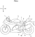
Figure 1 is a side view schematically showing a motorcycle including a seat rail structure according to an embodiment. -
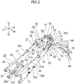
Figure 2 is a perspective view schematically showing the seat rail structure according to the embodiment. -
Figure 3 is a plan view schematically showing the seat rail structure according to the embodiment. -
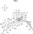
Figure 4 is a side view schematically showing the seat rail structure according to the embodiment. -
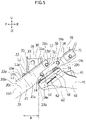
Figure 5 is an enlarged view of a part A inFigure 4 . - A motorcycle seat rail structure according to an embodiment will be described together with a motorcycle in which the seat rail structure is applied. Here, the motorcycle to which the motorcycle seat rail structure (hereinafter, simply referred to as a "seat rail structure" as necessary) is applied includes typically one front wheel and one rear wheel. However, the motorcycle may include two front wheels and one rear wheel.
- In
Figures 1 to 5 of the present embodiment, a front of avehicle body 1 of the motorcycle (hereinafter, simply referred to as "front" as necessary) is indicated by a one-headed arrow F, and a rear of the vehicle body 1 (hereinafter, simply referred to as "rear" as necessary) is indicated by a one-headed arrow R. Therefore, a front-rear direction of the vehicle body 1 (hereinafter, simply referred to as a "front-rear direction" as necessary) is indicated by the one-headed arrow F and the one-headed arrow R. InFigures 2 and3 , a width direction of the vehicle body 1 (hereinafter, simply referred to as a "width direction" as necessary) is indicated by a two-headed arrow W. InFigures 1 ,2 ,4 , and5 , an upper side of the vehicle body 1 (hereinafter, simply referred to as an "upper side" as necessary) is indicated by a one-headed arrow U, and a lower side of the vehicle body 1 (hereinafter, simply referred to as a "lower side" as necessary) is indicated by a one-headed arrow D. An up-down direction of the vehicle body 1 (hereinafter, simply referred to as an "up-down direction" as necessary) is indicated by the one-headed arrow U and the one-headed arrow D. - An outline of a
seat rail structure 10 and the motorcycle according to the present embodiment will be described with reference toFigures 1 to 5 . In other words, theseat rail structure 10 and the motorcycle are generally configured as follows. As shown inFigure 1 , theseat rail structure 10 includes aseat rail 11 that is installed on thevehicle body 1 of the motorcycle. - As shown in
Figures 2 and3 , theseat rail 11 includes twolateral members 20 spaced apart from each other in the width direction. Thelateral members 20 are located at lateral sides in the width direction of thevehicle body 1, respectively. As shown inFigures 2 to 5 , theseat rail 11 includes afirst coupling member 30 that couples the twolateral members 20 together. Thefirst coupling member 30 is configured to allow a seat 2 (shown inFigure 1 ) to be placed thereon. Each of the twolateral members 20 and thefirst coupling member 30 are configured to have a laminated structure in which a plurality of layers made of a fiber reinforced resin are laminated. - Each of the
lateral members 20 includes avertical wall 21 located at a lateral side in the width direction of thevehicle body 1. Each of thelateral members 20 includes anupper flange 22 protruding toward a center in the width direction of thevehicle body 1 from an upper edge of thevertical wall 21 of thelateral member 20. - The
first coupling member 30 includes two uppersurface contact portions 31 being in contact with theupper flanges 22 of the twolateral members 20. Each of the uppersurface contact portions 31 includes anouter edge 31a facing outward in the width direction of thevehicle body 1. Thefirst coupling member 30 includes two sidesurface contact portions 32 extending downward from theouter edges 31a of the two uppersurface contact portions 31, respectively. The two sidesurface contact portions 32 are in contact with thevertical walls 21 of the twolateral members 20, respectively. - The
seat rail structure 10 includes an uppersurface fastening portion 12 which fastens together the uppersurface contact portions 31 and theupper flanges 22 being in contact with the uppersurface contact portions 31. Theseat rail structure 10 further includes first side surface fasteningportions 13 which fasten together the sidesurface contact portions 32 and thevertical walls 21 being in contact with the sidesurface contact portions 32. - Furthermore, the
seat rail structure 10 and the motorcycle according to the present embodiment can be generally configured as follows. As shown inFigures 2 to 5 , each of thelateral members 20 includes acurved region 23 that is curved so as to be located closer to a center in the width direction of thevehicle body 1 as it extends toward a rear of thevehicle body 1 from a front of thevehicle body 1. As shown inFigure 5 , when thevehicle body 1 is viewed in the width direction, each of the uppersurface contact portions 31 is disposed to straddle an area P between afront end 23a and arear end 23b of thecurved region 23 in one of the twolateral members 20 being in contact with the uppersurface contact portion 31 in the front-rear direction of thevehicle body 1. - As shown in
Figures 2 to 5 , the two sidesurface contact portions 32 also extend downward fromrear areas 31b of theouter edges 31a in the two uppersurface contact portions 31 located closer to the rear of thevehicle body 1. - The
seat rail structure 10 includes arear fender 40 that covers an upper side of a rear wheel 3 (shown inFigure 1 ) of the motorcycle. Theseat rail structure 10 includes tworear fender brackets 50 being in contact with the twolateral members 20, respectively. Theseat rail structure 10 includes asecond coupling member 60 that couples the tworear fender brackets 50 together. - The
rear fender 40 is attached to the tworear fender brackets 50 through thesecond coupling member 60. Theseat rail structure 10 includes two second side surface fasteningportions 14 that fasten one of therear fender brackets 50 and thelateral member 20 being in contact with the one of therear fender brackets 50 together, respectively. Theseat rail structure 10 includes two second sidesurface fastening portions 14 located at one side in the width direction thereof and two second side surface fasteningportions 14 located at the other side in the width direction thereof. The two second side surface fasteningportions 14, which are located at one side or the other side in the width direction of theseat rail 11 are spaced apart from each other in the front-rear direction, and these two second side surface fasteningportions 14 are disposed at both sides in the front-rear direction of the first sidesurface fastening portion 13, respectively, above the first sidesurface fastening portion 13. - Referring to
Figures 1 and2 , the motorcycle according to the present embodiment can be configured in detail as follows. As shown inFigure 1 , thevehicle body 1 of the motorcycle includes aluggage rack 4. As shown inFigure 1 , theluggage rack 4 is located behind theseat 2. Theluggage rack 4 is adjacent to theseat 2 in the front-rear direction. - Referring to
Figures 1 and2 , theseat 2 and theluggage rack 4 are supported from below by theseat rail 11. Specifically, a rear in the front-rear direction of theseat 2 is supported from below by thefirst coupling member 30 of theseat rail 11. Theluggage rack 4 is also supported from below by thefirst coupling member 30 of theseat rail 11. As shown inFigure 1 , thevehicle body 1 includes afuel tank 5. Thefuel tank 5 is located in front of theseat 2. Thefuel tank 5 is also adjacent to theseat 2 in the front-rear direction. - The
vehicle body 1 includes a main frame 6. The main frame 6 is located in front of theseat rail 11, and is located below thefuel tank 5. The main frame 6 is adjacent to theseat rail 11 in the front-rear direction. Referring toFigures 1 and2 , afront end part 11a of theseat rail 11 in the front-rear direction is attached to the main frame 6. - As shown in
Figure 1 , thevehicle body 1 includes anouter panel 7. Theouter panel 7 is located below theseat 2. Theouter panel 7 is also adjacent to theseat 2 in the up-down direction. Theouter panel 7 covers anupper part 11b of theseat rail 11 from both outer sides in the width direction. Specifically, theouter panel 7 covers anupper part 20a of each of thelateral member 20 from the outer side in the width direction. However, the vehicle body may be configured so as not to include the outer panel. In this case, the vehicle body may be configured such that the lateral member is exposed to the outside of the vehicle body as an exterior member. - Referring to
Figures 2 to 5 , theseat rail structure 10 according to the present embodiment can be configured in detail as follows. Theseat rail 11 of theseat rail structure 10 includes athird coupling member 70 located behind thefirst coupling member 30. - The
third coupling member 70 couples twolateral members 20 to each other. Specifically, thethird coupling member 70 couplesrear end parts 20b in the front-rear direction of the twolateral members 20 to each other. Bothend parts 71 in the width direction of thethird coupling member 70 are in contact with theupper flanges 22 of the twolateral members 20, respectively. The bothend parts 71 of thethird coupling member 70 are also in contact with thevertical walls 21 of the twolateral members 20, respectively. The bothend parts 71 of thethird coupling member 70 are attached to therear end parts 20b of the twolateral members 20, respectively. - As shown in
Figure 5 , in theseat rail structure 10, the uppersurface fastening portion 12, the first sidesurface fastening portion 13, and the second sidesurface fastening portion 14 includefastening members fastening members surface fastening portion 12, the first sidesurface fastening portion 13, and the second sidesurface fastening portion 14 is configured such that a plurality of fastened portions are fastened between the head parts of thefastening members fastening members fastening members - Referring to
Figures 2 to 5 , each of thelateral members 20 can be configured in detail as follows. The twolateral members 20 are configured to be a substantially symmetrical with each other in the width direction. Thecurved region 23 of thelateral member 20 is located between arear end part 11c of theseat rail 11 and anintermediate part 11d in the front-rear direction of theseat rail 11. Specifically, thecurved region 23 of thelateral member 20 is located between therear end part 20b of thelateral member 20 and anintermediate part 20c in the vehicle front-rear direction of thelateral member 20. - The
vertical wall 21 of each of thelateral members 20 is formed in an elongated shape with a front-rear direction being a longitudinal direction. Thevertical wall 21 of each of thelateral members 20 includes anouter surface 21a facing outward in the width direction of thevehicle body 1. Two sidesurface contact portions 32 of thefirst coupling member 30 are in contact with theouter surfaces 21a of the twovertical walls 21, respectively. Tworear fender brackets 50 are in contact with theouter surfaces 21a of the twovertical walls 21, respectively. The bothend parts 71 of thethird coupling member 70 are in contact with theouter surfaces 21a of the twovertical walls 21, respectively. - The
upper flange 22 of each of thelateral members 20 is formed in an elongated shape with a front-rear direction being a longitudinal direction. Theupper flange 22 of each of thelateral members 20 includes anupper surface 22a facing upward. The two uppersurface contact portions 31 of thefirst coupling member 30 are in contact with theupper surfaces 22a of the twoupper flanges 22, respectively. The bothend parts 71 of thethird coupling member 70 are in contact with theupper surfaces 22a of the twoupper flanges 22, respectively. - Referring to
Figures 2 to 5 , thefirst coupling member 30 can be configured in detail as follows. Thefirst coupling member 30 includes a first coupling membermain body 33 that couples the two uppersurface contact portions 31 to each other. The first coupling membermain body 33 is formed in a substantially U-shape. - Referring to
Figures 2 to 5 , therear fender 40, therear fender bracket 50, and thesecond coupling member 60 can be configured in detail as follows. Therear fender 40 includes a rear fendermain body 41 that covers an upper side of therear wheel 3 of the motorcycle. Therear fender 40 includes a vehicle body-side attachment portion 42 used to attach therear fender 40 to theseat rail 11. The vehicle body-side attachment portion 42 is located at a front end part in the front-rear direction of the rear fendermain body 41. The vehicle body-side attachment portion 42 of therear fender 40 is disposed to be attached to therear end part 11c of theseat rail 11 from below together with the tworear fender brackets 50 and thesecond coupling member 60. - Each of the
rear fender brackets 50 includes a coupling-side attachment portion 51 to be attached to the vehicle body-side attachment portion 42 of therear fender 40 through thesecond coupling member 60. Specifically, the coupling-side attachment portions 51 of the tworear fender brackets 50 are attached to endparts 61 in the width direction of thesecond coupling member 60, respectively, and anintermediate part 62 in the width direction of thesecond coupling member 60 is attached to the vehicle body-side attachment portion 42 of therear fender 40. - Each
rear fender bracket 50 includes a sidesurface contact portion 52 that rises from the coupling-side attachment portion 51 of therear fender bracket 50. The sidesurface contact portions 52 of the tworear fender brackets 50 are in contact with thevertical walls 21 of the twolateral members 20, respectively. Specifically, the sidesurface contact portions 52 of the tworear fender brackets 50 are in contact with theouter surfaces 21a of thevertical walls 21 of the twolateral members 20, respectively. - Each of the side
surface contact portions 52 is disposed to be sandwiched between thevertical wall 21 being in contact therewith and the head parts or the fastened members (not shown) of thefastening members 14a of the two second sidesurface fastening portions 14 to be fastened to thevertical wall 21. Each of the sidesurface contact portions 52 is formed in an elongated shape to extend between the two second sidesurface fastening portions 14 to be fastened to thevertical wall 21 being in contact with such a sidesurface fastening portion 52. - As described above, the seat rail structure 10 according to the present embodiment is the motorcycle seat rail structure 10 including the seat rail 11 installed on the vehicle body 1 of the motorcycle, wherein: the seat rail 11 includes two lateral members 20 spaced apart from each other in the width direction of the vehicle body 1 and the first coupling member 30 configured to couple the two lateral members 20 to each other and to allow the seat 2 to be placed thereon; each of the two lateral members 20 and the first coupling member 30 is configured to have the laminated structure in which a plurality of layers made of the fiber reinforced resin are laminated; each of the lateral members 20 includes the vertical wall 21 located at the lateral side in the width direction of the vehicle body 1 and the upper flange 22 protruding toward the center in the width direction of the vehicle body 1 from the upper edge of the vertical wall 21; the first coupling member 30 includes the two upper surface contact portions 31 that are in contact with the upper flanges 22 of the two lateral members 20, respectively; each of the upper surface contact portions 31 includes the outer edge 31a facing outward in the width direction of the vehicle body 1; the first coupling member 30 includes the two side surface contact portions 32 extending downward from the outer edges 31a of the two upper surface contact portions 31, respectively; the two side surface contact portions 32 are in contact with vertical walls 21 of the two lateral members 20, respectively; the upper surface fastening portions 12 are provided to fasten together the upper surface contact portions 31 and the upper flanges 22, which are in contact with the upper surface contact portions 31; and the first side surface fastening portions 13 are provided to fasten together the side surface contact portions 32 and the vertical walls 21, which are in contact with the side surface contact portions 32.
- In such a
seat rail structure 10, thefirst coupling member 30 is coupled to the twolateral members 20, using the uppersurface contact portion 31 that is in contact with and fastened to theupper flange 22 of each of thelateral members 20, and the sidesurface contact portion 32 that is oriented in a different direction from the uppersurface contact portion 31 and that is in contact with and fastened to thevertical wall 21 of each of thelateral members 20. Therefore, even when a load is applied to the rear part of theseat rail 11 by an occupant, luggage, or the like due to traveling on the motorcycle on a rough road or riding of the motorcycle on a step, vibration in a specific vibration mode can be prevented from being amplified in one direction. As a result, such vibration can be prevented from being transmitted to the occupant through theseat 2. In other words, a vibration damping effect can be efficiently improved, and ride comfort of the occupant can be improved. - In addition, by the two side
surface contact portions 32 of thefirst coupling member 30, theseat rail 11 can be prevented from being deformed to open in the width direction of thevehicle body 1, for example, theseat rail 11 can be prevented from being deformed into a substantially trapezoidal shape when viewed from the front in thevehicle body 1. In this case, a shear load applied to the uppersurface fastening portion 12 and the first sidesurface fastening portion 13 can be prevented. As a result, for example, even when the uppersurface fastening portion 12 is configured such that thefastening member 12a is inserted into a through hole (not shown), and the contact between the fasteningmember 12a in the uppersurface fastening portion 12 and a peripheral edge (not shown) of the through hole occurs due to the load applied from theseat 2, delamination can be prevented from occurring in and around such a contact part. - In particular, since the first side
surface fastening portion 13 can be disposed to be separated downward as much as possible from a corner between theupper flange 22 and thevertical wall 21, the load applied to theseat rail 11 can be shared more with the first sidesurface fastening portion 13 than with the uppersurface fastening portion 12, and as a result, local stress concentration in and around the uppersurface fastening portion 12 can be prevented in particular. Accordingly, strength of theseat rail 11 can be efficiently improved. - In the
seat rail structure 10 according to the present embodiment, each of thelateral members 20 includes thecurved region 23 that is curved so as to be located closer to the center in the width direction of thevehicle body 1 as it extends toward the rear of thevehicle body 1 from the front of thevehicle body 1, and when thevehicle body 1 is viewed in the width direction thereof, each of the uppersurface contact portions 31 is disposed to extend over the area P between thefront end 23a and therear end 23b of thecurved region 23 in the front-rear direction of thevehicle body 1 in one of the twolateral members 20 being in contact with the uppersurface contact portion 31. - In cases in which a battery is disposed in a front part of an internal space of the
seat rail 11, it is necessary for the front part of the internal space to be formed wider than a rear part thereof. On the other hand, when the front part of the internal space of theseat rail 11 is formed wider than the rear part, thecurved region 23 is formed in theseat rail 11, and theseat rail 11 may be easily bent centering around thecurved region 23. - In contrast, in the
seat rail structure 10 according to the present embodiment, the uppersurface contact portion 31 of thefirst coupling member 30 to be fastened to each of thelateral members 20 is disposed to cover the area P between thefront end 23a and therear end 23b of thecurved region 23 of thelateral member 20 in the front-rear direction of thevehicle body 1. Therefore, the front part of the internal space of theseat rail 11 can be formed wider than the rear part thereof, thecurved region 23 of thelateral member 20 and the surroundings thereof can be reinforced by the uppersurface contact portion 31 of thefirst coupling member 30, and as a result, theseat rail 11 can be prevented from being bent centering around thecurved region 23. Accordingly, the strength of theseat rail 11 can be efficiently improved. - In the
seat rail structure 10 according to the present embodiment, the two sidesurface contact portions 32 extend downward from therear areas 31b of theouter edges 31a in the two uppersurface contact portions 31 located closer to the rear of thevehicle body 1. - Generally, when the motorcycle is travelling, the rear part of the seat rail is more subjected to the load from the occupant than the front part thereof. Taking this into consideration, in the
seat rail structure 10 according to the present embodiment, since the first sidesurface fastening portion 13, which fastens the sidesurface contact portion 32 extending downward from therear area 31b of theouter edge 31a of the uppersurface contact portion 31 in thefirst coupling member 30 and thevertical wall 21 of thelateral member 20, can be disposed to be separated downward as much as possible from the corner between theupper flange 22 and thevertical wall 21, the load applied to theseat rail 11 can be shared more with the first sidesurface fastening portion 13 than with the uppersurface fastening portion 12. As a result, for example, even when the uppersurface fastening portion 12 is configured such that thefastening member 12a is inserted into the through hole (not shown), and the contact between the fasteningmember 12a in the uppersurface fastening portion 12 and the peripheral edge (not shown) of the through hole occurs due to the load applied from theseat 2, delamination can be prevented from occurring in and around such a contact part. - The
seat rail structure 10 according to the present embodiment includes: therear fender 40 that covers the upper side of therear wheel 3 of the motorcycle; the tworear fender brackets 50 being in contact with the twolateral members 20, respectively, and thesecond coupling member 60 that couples the tworear fender brackets 50, wherein therear fender 40 is attached to the tworear fender brackets 50 through thesecond coupling member 60, and the two second sidesurface fastening portions 14, which fasten therear fender brackets 50 and thelateral members 20 being in contact with therear fender brackets 50 together, are spaced apart from each other in the front-rear direction of thevehicle body 1, and are disposed at both sides of the first sidesurface fastening portion 13 in the front-rear direction of thevehicle body 1, respectively, above the first sidesurface fastening portion 13. - In such a
seat rail structure 10, the load applied to thevertical wall 21 of thelateral member 20 from the first sidesurface fastening portion 13 can be distributed by the two second sidesurface fastening portions 14. Therefore, the stress concentration in the lower part of thelateral member 20 can be prevented in particular. Accordingly, the strength of theseat rail 11 can be efficiently improved. - Although the embodiment of the present invention has been described above, the present invention is not limited to the above-described embodiment, and the present invention can be modified and changed based on the technical idea thereof.
-
- 1
- vehicle body
- 2
- seat
- 3
- rear wheel
- 10
- seat rail structure
- 11
- seat rail
- 12
- upper surface fastening portion
- 13
- first side surface fastening portion
- 14
- second side surface fastening portion
- 20
- lateral member
- 21
- vertical wall
- 22
- upper flange
- 23
- curved region
- 23 a
- front end
- 23b
- rear end
- 30
- first coupling member
- 31
- upper surface contact portion
- 31a
- outer edge
- 31b
- rear area
- 32
- side surface contact portion
- 40
- rear fender
- 50
- rear fender bracket
- 60
- second coupling member
- P
- area
Claims (4)
- A motorcycle seat rail structure comprising a seat rail installed on a vehicle body of a motorcycle, wherein:the seat rail includes two lateral members spaced apart from each other in a width direction of the vehicle body and a first coupling member configured to couple the two lateral members to each other and to allow a seat to be placed thereon;each of the two lateral members and the first coupling member is configured to have a laminated structure in which a plurality of layers made of a fiber reinforced resin are laminated;each of the lateral members includes a vertical wall located at a lateral side in the width direction of the vehicle body and an upper flange protruding toward a center in the width direction of the vehicle body from an upper edge of the vertical wall;the first coupling member includes two upper surface contact portions that are in contact with the upper flanges of the two lateral members, respectively;each of the upper surface contact portions includes an outer edge facing outward in the width direction of the vehicle body;the first coupling member includes two side surface contact portions extending downward from the outer edges of the two upper surface contact portions, respectively;the two side surface contact portions are in contact with the vertical walls of the two lateral members, respectively;an upper fastening portion is provided to fasten each of the upper surface contact portions and the upper flange which is in contact with the each of the upper surface contact portions, together; anda first side surface fastening portion is provided to fasten together each of the side surface contact portions and the vertical wall, which is in contact with the each of the side surface contact portions.
- The motorcycle seat rail structure according to claim 1, wherein:each of the lateral members includes a curved region that is curved so as to be located closer to the center in the width direction of the vehicle body as it extends toward a rear of the vehicle body from a front of the vehicle body; andwhen the vehicle body is viewed in the width direction thereof, each of the upper surface contact portions is disposed to extend over an area between a front end and a rear end of the curved region in one of the two lateral members being in contact with the each of the upper surface contact portions in a front-rear direction of the vehicle body.
- The motorcycle seat rail structure according to claim 1 or 2, wherein
the two side surface contact portions extend downward from rear areas of the outer edges in the two upper surface contact portions located closer to a rear of the vehicle body. - The motorcycle seat rail structure according to any one of claims 1 to 3, further comprising:a rear fender that covers an upper side of a rear wheel of the motorcycle;two rear fender brackets being in contact with the two lateral members, respectively; anda second coupling member that couples the two rear fender brackets, wherein:the rear fender is attached to the two rear fender brackets through the second coupling member; andtwo second side surface fastening portions, which fasten the rear fender brackets and the lateral members being in contact with the rear fender brackets together, are spaced apart from each other in the front-rear direction of the vehicle body, and are disposed at both sides of the first side surface fastening portion in the front-rear direction of the vehicle body, respectively, above the first side surface fastening portion.
Applications Claiming Priority (1)
| Application Number | Priority Date | Filing Date | Title |
|---|---|---|---|
| JP2020175344A JP7571458B2 (en) | 2020-10-19 | 2020-10-19 | Seat rail structure for motorcycles |
Publications (2)
| Publication Number | Publication Date |
|---|---|
| EP3984726A1 true EP3984726A1 (en) | 2022-04-20 |
| EP3984726B1 EP3984726B1 (en) | 2024-08-21 |
Family
ID=78080228
Family Applications (1)
| Application Number | Title | Priority Date | Filing Date |
|---|---|---|---|
| EP21201260.3A Active EP3984726B1 (en) | 2020-10-19 | 2021-10-06 | Motorcycle seat rail structure |
Country Status (3)
| Country | Link |
|---|---|
| US (1) | US12195127B2 (en) |
| EP (1) | EP3984726B1 (en) |
| JP (1) | JP7571458B2 (en) |
Families Citing this family (4)
| Publication number | Priority date | Publication date | Assignee | Title |
|---|---|---|---|---|
| JP7335549B2 (en) * | 2019-11-28 | 2023-08-30 | スズキ株式会社 | Seat rail structure for motorcycle |
| JP2021126933A (en) * | 2020-02-12 | 2021-09-02 | ヤマハ発動機株式会社 | Saddle-riding vehicle |
| JP7517026B2 (en) * | 2020-09-24 | 2024-07-17 | スズキ株式会社 | Front fender |
| JP7480668B2 (en) * | 2020-10-16 | 2024-05-10 | スズキ株式会社 | Body structure of saddle-type vehicle |
Citations (3)
| Publication number | Priority date | Publication date | Assignee | Title |
|---|---|---|---|---|
| WO2015033425A1 (en) | 2013-09-05 | 2015-03-12 | 本田技研工業株式会社 | Vehicle body frame structure for saddled vehicle |
| JP2019180554A (en) * | 2018-04-03 | 2019-10-24 | テイ・エス テック株式会社 | Straddling type seat |
| US20200269942A1 (en) * | 2019-02-22 | 2020-08-27 | Suzuki Motor Corporation | Seat Rail of Motorcycle |
Family Cites Families (8)
| Publication number | Priority date | Publication date | Assignee | Title |
|---|---|---|---|---|
| JP4087668B2 (en) | 2002-09-10 | 2008-05-21 | 本田技研工業株式会社 | Seat rail structure |
| JP4980096B2 (en) | 2007-02-28 | 2012-07-18 | 本田技研工業株式会社 | Motorcycle seat rail structure |
| JP6140753B2 (en) * | 2015-03-31 | 2017-05-31 | 本田技研工業株式会社 | Saddle riding vehicle |
| JP6789883B2 (en) * | 2017-05-26 | 2020-11-25 | スズキ株式会社 | Saddle-type vehicle |
| JP6708687B2 (en) * | 2018-03-28 | 2020-06-10 | 本田技研工業株式会社 | Motorcycle seat frame |
| JP7029996B2 (en) * | 2018-03-28 | 2022-03-04 | 本田技研工業株式会社 | Seat frame structure for saddle-riding vehicles |
| JP7218596B2 (en) | 2019-02-04 | 2023-02-07 | スズキ株式会社 | Edge structure of fiber reinforced resin structure |
| WO2020178859A1 (en) | 2019-03-07 | 2020-09-10 | Hero MotoCorp Limited | Rear end structure of vehicle |
-
2020
- 2020-10-19 JP JP2020175344A patent/JP7571458B2/en active Active
-
2021
- 2021-10-06 EP EP21201260.3A patent/EP3984726B1/en active Active
- 2021-10-13 US US17/500,056 patent/US12195127B2/en active Active
Patent Citations (4)
| Publication number | Priority date | Publication date | Assignee | Title |
|---|---|---|---|---|
| WO2015033425A1 (en) | 2013-09-05 | 2015-03-12 | 本田技研工業株式会社 | Vehicle body frame structure for saddled vehicle |
| US20160200387A1 (en) * | 2013-09-05 | 2016-07-14 | Honda Motor Co., Ltd. | Vehicle body frame structure for saddled vehicle |
| JP2019180554A (en) * | 2018-04-03 | 2019-10-24 | テイ・エス テック株式会社 | Straddling type seat |
| US20200269942A1 (en) * | 2019-02-22 | 2020-08-27 | Suzuki Motor Corporation | Seat Rail of Motorcycle |
Also Published As
| Publication number | Publication date |
|---|---|
| EP3984726B1 (en) | 2024-08-21 |
| US20220119060A1 (en) | 2022-04-21 |
| US12195127B2 (en) | 2025-01-14 |
| JP7571458B2 (en) | 2024-10-23 |
| JP2022071223A (en) | 2022-05-16 |
Similar Documents
| Publication | Publication Date | Title |
|---|---|---|
| EP3984726B1 (en) | Motorcycle seat rail structure | |
| US10279693B2 (en) | Vehicle front portion structure | |
| EP2740651B1 (en) | Vehicle body lateral structure | |
| EP1808362B1 (en) | vehicle body | |
| EP3190032B1 (en) | Vehicle rear portion structure | |
| KR102910901B1 (en) | Vehicle body structure | |
| US11110785B2 (en) | Vehicle rear portion structure | |
| CN112739611B (en) | Vehicle body lower structure | |
| CN106965859A (en) | Vehicle rear body structure | |
| CN103998273A (en) | Vehicle body structure | |
| JP5984052B2 (en) | Battery pack positioning pin bracket | |
| EP4063159B1 (en) | Lower structure of electric vehicle | |
| CN103619695B (en) | Underbody structure at the front of the vehicle | |
| CN110282015A (en) | Back structure of vehicle body | |
| CN104736419B (en) | Vehicle rear structure | |
| EP3992064B1 (en) | Motorcycle seat rail and method of manufacturing the same | |
| JPH08175203A (en) | Fuel tank mounting structure | |
| US10414444B2 (en) | Vehicle rear end structure | |
| EP4063241A1 (en) | Undercover structure for vehicle | |
| JP2009035106A (en) | Front body structure of automobile | |
| JP7177816B2 (en) | Body front structure | |
| JP2007216903A (en) | Lower body structure of automobile | |
| JP5475523B2 (en) | Rear floor structure of automobile | |
| KR102898360B1 (en) | Battery unit for vehicle and underbody of vehicle including the same | |
| JP4100389B2 (en) | Front body structure of the vehicle |
Legal Events
| Date | Code | Title | Description |
|---|---|---|---|
| PUAI | Public reference made under article 153(3) epc to a published international application that has entered the european phase |
Free format text: ORIGINAL CODE: 0009012 |
|
| STAA | Information on the status of an ep patent application or granted ep patent |
Free format text: STATUS: REQUEST FOR EXAMINATION WAS MADE |
|
| 17P | Request for examination filed |
Effective date: 20211006 |
|
| AK | Designated contracting states |
Kind code of ref document: A1 Designated state(s): AL AT BE BG CH CY CZ DE DK EE ES FI FR GB GR HR HU IE IS IT LI LT LU LV MC MK MT NL NO PL PT RO RS SE SI SK SM TR |
|
| GRAP | Despatch of communication of intention to grant a patent |
Free format text: ORIGINAL CODE: EPIDOSNIGR1 |
|
| STAA | Information on the status of an ep patent application or granted ep patent |
Free format text: STATUS: GRANT OF PATENT IS INTENDED |
|
| INTG | Intention to grant announced |
Effective date: 20240319 |
|
| GRAJ | Information related to disapproval of communication of intention to grant by the applicant or resumption of examination proceedings by the epo deleted |
Free format text: ORIGINAL CODE: EPIDOSDIGR1 |
|
| STAA | Information on the status of an ep patent application or granted ep patent |
Free format text: STATUS: REQUEST FOR EXAMINATION WAS MADE |
|
| GRAP | Despatch of communication of intention to grant a patent |
Free format text: ORIGINAL CODE: EPIDOSNIGR1 |
|
| STAA | Information on the status of an ep patent application or granted ep patent |
Free format text: STATUS: GRANT OF PATENT IS INTENDED |
|
| INTC | Intention to grant announced (deleted) | ||
| INTG | Intention to grant announced |
Effective date: 20240529 |
|
| GRAS | Grant fee paid |
Free format text: ORIGINAL CODE: EPIDOSNIGR3 |
|
| GRAA | (expected) grant |
Free format text: ORIGINAL CODE: 0009210 |
|
| STAA | Information on the status of an ep patent application or granted ep patent |
Free format text: STATUS: THE PATENT HAS BEEN GRANTED |
|
| AK | Designated contracting states |
Kind code of ref document: B1 Designated state(s): AL AT BE BG CH CY CZ DE DK EE ES FI FR GB GR HR HU IE IS IT LI LT LU LV MC MK MT NL NO PL PT RO RS SE SI SK SM TR |
|
| REG | Reference to a national code |
Ref country code: GB Ref legal event code: FG4D |
|
| REG | Reference to a national code |
Ref country code: CH Ref legal event code: EP |
|
| REG | Reference to a national code |
Ref country code: IE Ref legal event code: FG4D |
|
| REG | Reference to a national code |
Ref country code: DE Ref legal event code: R096 Ref document number: 602021017451 Country of ref document: DE |
|
| REG | Reference to a national code |
Ref country code: LT Ref legal event code: MG9D |
|
| REG | Reference to a national code |
Ref country code: NL Ref legal event code: MP Effective date: 20240821 |
|
| PG25 | Lapsed in a contracting state [announced via postgrant information from national office to epo] |
Ref country code: NO Free format text: LAPSE BECAUSE OF FAILURE TO SUBMIT A TRANSLATION OF THE DESCRIPTION OR TO PAY THE FEE WITHIN THE PRESCRIBED TIME-LIMIT Effective date: 20241121 |
|
| REG | Reference to a national code |
Ref country code: AT Ref legal event code: MK05 Ref document number: 1715146 Country of ref document: AT Kind code of ref document: T Effective date: 20240821 |
|
| PG25 | Lapsed in a contracting state [announced via postgrant information from national office to epo] |
Ref country code: NL Free format text: LAPSE BECAUSE OF FAILURE TO SUBMIT A TRANSLATION OF THE DESCRIPTION OR TO PAY THE FEE WITHIN THE PRESCRIBED TIME-LIMIT Effective date: 20240821 Ref country code: FI Free format text: LAPSE BECAUSE OF FAILURE TO SUBMIT A TRANSLATION OF THE DESCRIPTION OR TO PAY THE FEE WITHIN THE PRESCRIBED TIME-LIMIT Effective date: 20240821 Ref country code: GR Free format text: LAPSE BECAUSE OF FAILURE TO SUBMIT A TRANSLATION OF THE DESCRIPTION OR TO PAY THE FEE WITHIN THE PRESCRIBED TIME-LIMIT Effective date: 20241122 Ref country code: PL Free format text: LAPSE BECAUSE OF FAILURE TO SUBMIT A TRANSLATION OF THE DESCRIPTION OR TO PAY THE FEE WITHIN THE PRESCRIBED TIME-LIMIT Effective date: 20240821 Ref country code: PT Free format text: LAPSE BECAUSE OF FAILURE TO SUBMIT A TRANSLATION OF THE DESCRIPTION OR TO PAY THE FEE WITHIN THE PRESCRIBED TIME-LIMIT Effective date: 20241223 |
|
| PG25 | Lapsed in a contracting state [announced via postgrant information from national office to epo] |
Ref country code: BG Free format text: LAPSE BECAUSE OF FAILURE TO SUBMIT A TRANSLATION OF THE DESCRIPTION OR TO PAY THE FEE WITHIN THE PRESCRIBED TIME-LIMIT Effective date: 20240821 |
|
| PG25 | Lapsed in a contracting state [announced via postgrant information from national office to epo] |
Ref country code: LV Free format text: LAPSE BECAUSE OF FAILURE TO SUBMIT A TRANSLATION OF THE DESCRIPTION OR TO PAY THE FEE WITHIN THE PRESCRIBED TIME-LIMIT Effective date: 20240821 |
|
| PG25 | Lapsed in a contracting state [announced via postgrant information from national office to epo] |
Ref country code: IS Free format text: LAPSE BECAUSE OF FAILURE TO SUBMIT A TRANSLATION OF THE DESCRIPTION OR TO PAY THE FEE WITHIN THE PRESCRIBED TIME-LIMIT Effective date: 20241221 Ref country code: AT Free format text: LAPSE BECAUSE OF FAILURE TO SUBMIT A TRANSLATION OF THE DESCRIPTION OR TO PAY THE FEE WITHIN THE PRESCRIBED TIME-LIMIT Effective date: 20240821 |
|
| PG25 | Lapsed in a contracting state [announced via postgrant information from national office to epo] |
Ref country code: HR Free format text: LAPSE BECAUSE OF FAILURE TO SUBMIT A TRANSLATION OF THE DESCRIPTION OR TO PAY THE FEE WITHIN THE PRESCRIBED TIME-LIMIT Effective date: 20240821 |
|
| PG25 | Lapsed in a contracting state [announced via postgrant information from national office to epo] |
Ref country code: ES Free format text: LAPSE BECAUSE OF FAILURE TO SUBMIT A TRANSLATION OF THE DESCRIPTION OR TO PAY THE FEE WITHIN THE PRESCRIBED TIME-LIMIT Effective date: 20240821 Ref country code: RS Free format text: LAPSE BECAUSE OF FAILURE TO SUBMIT A TRANSLATION OF THE DESCRIPTION OR TO PAY THE FEE WITHIN THE PRESCRIBED TIME-LIMIT Effective date: 20241121 |
|
| PG25 | Lapsed in a contracting state [announced via postgrant information from national office to epo] |
Ref country code: RS Free format text: LAPSE BECAUSE OF FAILURE TO SUBMIT A TRANSLATION OF THE DESCRIPTION OR TO PAY THE FEE WITHIN THE PRESCRIBED TIME-LIMIT Effective date: 20241121 Ref country code: PT Free format text: LAPSE BECAUSE OF FAILURE TO SUBMIT A TRANSLATION OF THE DESCRIPTION OR TO PAY THE FEE WITHIN THE PRESCRIBED TIME-LIMIT Effective date: 20241223 Ref country code: PL Free format text: LAPSE BECAUSE OF FAILURE TO SUBMIT A TRANSLATION OF THE DESCRIPTION OR TO PAY THE FEE WITHIN THE PRESCRIBED TIME-LIMIT Effective date: 20240821 Ref country code: NO Free format text: LAPSE BECAUSE OF FAILURE TO SUBMIT A TRANSLATION OF THE DESCRIPTION OR TO PAY THE FEE WITHIN THE PRESCRIBED TIME-LIMIT Effective date: 20241121 Ref country code: NL Free format text: LAPSE BECAUSE OF FAILURE TO SUBMIT A TRANSLATION OF THE DESCRIPTION OR TO PAY THE FEE WITHIN THE PRESCRIBED TIME-LIMIT Effective date: 20240821 Ref country code: LV Free format text: LAPSE BECAUSE OF FAILURE TO SUBMIT A TRANSLATION OF THE DESCRIPTION OR TO PAY THE FEE WITHIN THE PRESCRIBED TIME-LIMIT Effective date: 20240821 Ref country code: IS Free format text: LAPSE BECAUSE OF FAILURE TO SUBMIT A TRANSLATION OF THE DESCRIPTION OR TO PAY THE FEE WITHIN THE PRESCRIBED TIME-LIMIT Effective date: 20241221 Ref country code: HR Free format text: LAPSE BECAUSE OF FAILURE TO SUBMIT A TRANSLATION OF THE DESCRIPTION OR TO PAY THE FEE WITHIN THE PRESCRIBED TIME-LIMIT Effective date: 20240821 Ref country code: GR Free format text: LAPSE BECAUSE OF FAILURE TO SUBMIT A TRANSLATION OF THE DESCRIPTION OR TO PAY THE FEE WITHIN THE PRESCRIBED TIME-LIMIT Effective date: 20241122 Ref country code: FI Free format text: LAPSE BECAUSE OF FAILURE TO SUBMIT A TRANSLATION OF THE DESCRIPTION OR TO PAY THE FEE WITHIN THE PRESCRIBED TIME-LIMIT Effective date: 20240821 Ref country code: ES Free format text: LAPSE BECAUSE OF FAILURE TO SUBMIT A TRANSLATION OF THE DESCRIPTION OR TO PAY THE FEE WITHIN THE PRESCRIBED TIME-LIMIT Effective date: 20240821 Ref country code: BG Free format text: LAPSE BECAUSE OF FAILURE TO SUBMIT A TRANSLATION OF THE DESCRIPTION OR TO PAY THE FEE WITHIN THE PRESCRIBED TIME-LIMIT Effective date: 20240821 Ref country code: AT Free format text: LAPSE BECAUSE OF FAILURE TO SUBMIT A TRANSLATION OF THE DESCRIPTION OR TO PAY THE FEE WITHIN THE PRESCRIBED TIME-LIMIT Effective date: 20240821 |
|
| PG25 | Lapsed in a contracting state [announced via postgrant information from national office to epo] |
Ref country code: DK Free format text: LAPSE BECAUSE OF FAILURE TO SUBMIT A TRANSLATION OF THE DESCRIPTION OR TO PAY THE FEE WITHIN THE PRESCRIBED TIME-LIMIT Effective date: 20240821 Ref country code: RO Free format text: LAPSE BECAUSE OF FAILURE TO SUBMIT A TRANSLATION OF THE DESCRIPTION OR TO PAY THE FEE WITHIN THE PRESCRIBED TIME-LIMIT Effective date: 20240821 Ref country code: SM Free format text: LAPSE BECAUSE OF FAILURE TO SUBMIT A TRANSLATION OF THE DESCRIPTION OR TO PAY THE FEE WITHIN THE PRESCRIBED TIME-LIMIT Effective date: 20240821 |
|
| PG25 | Lapsed in a contracting state [announced via postgrant information from national office to epo] |
Ref country code: EE Free format text: LAPSE BECAUSE OF FAILURE TO SUBMIT A TRANSLATION OF THE DESCRIPTION OR TO PAY THE FEE WITHIN THE PRESCRIBED TIME-LIMIT Effective date: 20240821 |
|
| PG25 | Lapsed in a contracting state [announced via postgrant information from national office to epo] |
Ref country code: CZ Free format text: LAPSE BECAUSE OF FAILURE TO SUBMIT A TRANSLATION OF THE DESCRIPTION OR TO PAY THE FEE WITHIN THE PRESCRIBED TIME-LIMIT Effective date: 20240821 |
|
| PG25 | Lapsed in a contracting state [announced via postgrant information from national office to epo] |
Ref country code: SK Free format text: LAPSE BECAUSE OF FAILURE TO SUBMIT A TRANSLATION OF THE DESCRIPTION OR TO PAY THE FEE WITHIN THE PRESCRIBED TIME-LIMIT Effective date: 20240821 Ref country code: IT Free format text: LAPSE BECAUSE OF FAILURE TO SUBMIT A TRANSLATION OF THE DESCRIPTION OR TO PAY THE FEE WITHIN THE PRESCRIBED TIME-LIMIT Effective date: 20240821 |
|
| REG | Reference to a national code |
Ref country code: DE Ref legal event code: R097 Ref document number: 602021017451 Country of ref document: DE |
|
| REG | Reference to a national code |
Ref country code: CH Ref legal event code: PL |
|
| PLBE | No opposition filed within time limit |
Free format text: ORIGINAL CODE: 0009261 |
|
| STAA | Information on the status of an ep patent application or granted ep patent |
Free format text: STATUS: NO OPPOSITION FILED WITHIN TIME LIMIT |
|
| PG25 | Lapsed in a contracting state [announced via postgrant information from national office to epo] |
Ref country code: MC Free format text: LAPSE BECAUSE OF FAILURE TO SUBMIT A TRANSLATION OF THE DESCRIPTION OR TO PAY THE FEE WITHIN THE PRESCRIBED TIME-LIMIT Effective date: 20240821 |
|
| PG25 | Lapsed in a contracting state [announced via postgrant information from national office to epo] |
Ref country code: BE Free format text: LAPSE BECAUSE OF NON-PAYMENT OF DUE FEES Effective date: 20241031 Ref country code: LU Free format text: LAPSE BECAUSE OF NON-PAYMENT OF DUE FEES Effective date: 20241006 |
|
| PG25 | Lapsed in a contracting state [announced via postgrant information from national office to epo] |
Ref country code: CH Free format text: LAPSE BECAUSE OF NON-PAYMENT OF DUE FEES Effective date: 20241031 |
|
| 26N | No opposition filed |
Effective date: 20250522 |
|
| REG | Reference to a national code |
Ref country code: BE Ref legal event code: MM Effective date: 20241031 |
|
| PG25 | Lapsed in a contracting state [announced via postgrant information from national office to epo] |
Ref country code: SE Free format text: LAPSE BECAUSE OF FAILURE TO SUBMIT A TRANSLATION OF THE DESCRIPTION OR TO PAY THE FEE WITHIN THE PRESCRIBED TIME-LIMIT Effective date: 20240821 |
|
| PGFP | Annual fee paid to national office [announced via postgrant information from national office to epo] |
Ref country code: FR Payment date: 20250908 Year of fee payment: 5 |
|
| PG25 | Lapsed in a contracting state [announced via postgrant information from national office to epo] |
Ref country code: IE Free format text: LAPSE BECAUSE OF NON-PAYMENT OF DUE FEES Effective date: 20241006 |
|
| PGFP | Annual fee paid to national office [announced via postgrant information from national office to epo] |
Ref country code: DE Payment date: 20250902 Year of fee payment: 5 |
|
| PG25 | Lapsed in a contracting state [announced via postgrant information from national office to epo] |
Ref country code: CY Free format text: LAPSE BECAUSE OF FAILURE TO SUBMIT A TRANSLATION OF THE DESCRIPTION OR TO PAY THE FEE WITHIN THE PRESCRIBED TIME-LIMIT; INVALID AB INITIO Effective date: 20211006 |
|
| PG25 | Lapsed in a contracting state [announced via postgrant information from national office to epo] |
Ref country code: HU Free format text: LAPSE BECAUSE OF FAILURE TO SUBMIT A TRANSLATION OF THE DESCRIPTION OR TO PAY THE FEE WITHIN THE PRESCRIBED TIME-LIMIT; INVALID AB INITIO Effective date: 20211006 |