EP3984711A1 - Composite chopper for superabsorbent hydrogel - Google Patents
Composite chopper for superabsorbent hydrogel Download PDFInfo
- Publication number
- EP3984711A1 EP3984711A1 EP20889315.6A EP20889315A EP3984711A1 EP 3984711 A1 EP3984711 A1 EP 3984711A1 EP 20889315 A EP20889315 A EP 20889315A EP 3984711 A1 EP3984711 A1 EP 3984711A1
- Authority
- EP
- European Patent Office
- Prior art keywords
- hydrogel
- cutting
- barrel body
- transfer
- screw member
- Prior art date
- Legal status (The legal status is an assumption and is not a legal conclusion. Google has not performed a legal analysis and makes no representation as to the accuracy of the status listed.)
- Pending
Links
- 239000000017 hydrogel Substances 0.000 title claims abstract description 89
- 239000002131 composite material Substances 0.000 title 1
- 238000005520 cutting process Methods 0.000 claims abstract description 66
- 238000007599 discharging Methods 0.000 claims abstract description 7
- 239000002245 particle Substances 0.000 claims description 16
- 238000000034 method Methods 0.000 description 10
- 239000011295 pitch Substances 0.000 description 10
- 229920000642 polymer Polymers 0.000 description 9
- 238000006116 polymerization reaction Methods 0.000 description 9
- 238000004898 kneading Methods 0.000 description 8
- HEMHJVSKTPXQMS-UHFFFAOYSA-M Sodium hydroxide Chemical compound [OH-].[Na+] HEMHJVSKTPXQMS-UHFFFAOYSA-M 0.000 description 6
- 230000000052 comparative effect Effects 0.000 description 5
- 238000001035 drying Methods 0.000 description 5
- 239000000463 material Substances 0.000 description 5
- 238000010298 pulverizing process Methods 0.000 description 5
- 239000000654 additive Substances 0.000 description 4
- 230000000996 additive effect Effects 0.000 description 4
- 238000002347 injection Methods 0.000 description 4
- 239000007924 injection Substances 0.000 description 4
- 229920000247 superabsorbent polymer Polymers 0.000 description 4
- 239000004094 surface-active agent Substances 0.000 description 4
- HVUMOYIDDBPOLL-XWVZOOPGSA-N Sorbitan monostearate Chemical compound CCCCCCCCCCCCCCCCCC(=O)OC[C@@H](O)[C@H]1OC[C@H](O)[C@H]1O HVUMOYIDDBPOLL-XWVZOOPGSA-N 0.000 description 3
- 239000007864 aqueous solution Substances 0.000 description 3
- 230000007423 decrease Effects 0.000 description 3
- 230000000694 effects Effects 0.000 description 3
- 230000008569 process Effects 0.000 description 3
- 238000012719 thermal polymerization Methods 0.000 description 3
- 230000009471 action Effects 0.000 description 2
- 239000003795 chemical substances by application Substances 0.000 description 2
- 238000010528 free radical solution polymerization reaction Methods 0.000 description 2
- 239000000499 gel Substances 0.000 description 2
- 230000002209 hydrophobic effect Effects 0.000 description 2
- 238000004519 manufacturing process Methods 0.000 description 2
- 239000000203 mixture Substances 0.000 description 2
- 239000000178 monomer Substances 0.000 description 2
- 238000003825 pressing Methods 0.000 description 2
- 235000011121 sodium hydroxide Nutrition 0.000 description 2
- 238000010557 suspension polymerization reaction Methods 0.000 description 2
- XLYOFNOQVPJJNP-UHFFFAOYSA-N water Substances O XLYOFNOQVPJJNP-UHFFFAOYSA-N 0.000 description 2
- LCPVQAHEFVXVKT-UHFFFAOYSA-N 2-(2,4-difluorophenoxy)pyridin-3-amine Chemical compound NC1=CC=CN=C1OC1=CC=C(F)C=C1F LCPVQAHEFVXVKT-UHFFFAOYSA-N 0.000 description 1
- SXNICUVVDOTUPD-UHFFFAOYSA-N CC1=CC(C)=CC(C)=C1C(=O)P(=O)C1=CC=CC=C1 Chemical compound CC1=CC(C)=CC(C)=C1C(=O)P(=O)C1=CC=CC=C1 SXNICUVVDOTUPD-UHFFFAOYSA-N 0.000 description 1
- 239000002202 Polyethylene glycol Substances 0.000 description 1
- 235000021355 Stearic acid Nutrition 0.000 description 1
- 230000002745 absorbent Effects 0.000 description 1
- 239000002250 absorbent Substances 0.000 description 1
- ATMLPEJAVWINOF-UHFFFAOYSA-N acrylic acid acrylic acid Chemical compound OC(=O)C=C.OC(=O)C=C ATMLPEJAVWINOF-UHFFFAOYSA-N 0.000 description 1
- 230000008901 benefit Effects 0.000 description 1
- 230000008859 change Effects 0.000 description 1
- 239000003638 chemical reducing agent Substances 0.000 description 1
- 238000010276 construction Methods 0.000 description 1
- 238000001816 cooling Methods 0.000 description 1
- 230000003247 decreasing effect Effects 0.000 description 1
- 125000004386 diacrylate group Chemical group 0.000 description 1
- 238000009826 distribution Methods 0.000 description 1
- 235000013305 food Nutrition 0.000 description 1
- 238000010413 gardening Methods 0.000 description 1
- 230000001678 irradiating effect Effects 0.000 description 1
- 238000012423 maintenance Methods 0.000 description 1
- 230000014759 maintenance of location Effects 0.000 description 1
- 239000007769 metal material Substances 0.000 description 1
- 238000002156 mixing Methods 0.000 description 1
- 238000012986 modification Methods 0.000 description 1
- 230000004048 modification Effects 0.000 description 1
- QIQXTHQIDYTFRH-UHFFFAOYSA-N octadecanoic acid Chemical compound CCCCCCCCCCCCCCCCCC(O)=O QIQXTHQIDYTFRH-UHFFFAOYSA-N 0.000 description 1
- OQCDKBAXFALNLD-UHFFFAOYSA-N octadecanoic acid Natural products CCCCCCCC(C)CCCCCCCCC(O)=O OQCDKBAXFALNLD-UHFFFAOYSA-N 0.000 description 1
- 238000010951 particle size reduction Methods 0.000 description 1
- 230000000704 physical effect Effects 0.000 description 1
- 229920001223 polyethylene glycol Polymers 0.000 description 1
- 229920000671 polyethylene glycol diacrylate Polymers 0.000 description 1
- 239000002861 polymer material Substances 0.000 description 1
- 239000003505 polymerization initiator Substances 0.000 description 1
- 230000008439 repair process Effects 0.000 description 1
- CHQMHPLRPQMAMX-UHFFFAOYSA-L sodium persulfate Substances [Na+].[Na+].[O-]S(=O)(=O)OOS([O-])(=O)=O CHQMHPLRPQMAMX-UHFFFAOYSA-L 0.000 description 1
- 239000002689 soil Substances 0.000 description 1
- 239000007787 solid Substances 0.000 description 1
- 239000000243 solution Substances 0.000 description 1
- 239000008117 stearic acid Substances 0.000 description 1
- 229920001059 synthetic polymer Polymers 0.000 description 1
Images



Classifications
-
- B—PERFORMING OPERATIONS; TRANSPORTING
- B29—WORKING OF PLASTICS; WORKING OF SUBSTANCES IN A PLASTIC STATE IN GENERAL
- B29B—PREPARATION OR PRETREATMENT OF THE MATERIAL TO BE SHAPED; MAKING GRANULES OR PREFORMS; RECOVERY OF PLASTICS OR OTHER CONSTITUENTS OF WASTE MATERIAL CONTAINING PLASTICS
- B29B9/00—Making granules
- B29B9/02—Making granules by dividing preformed material
- B29B9/06—Making granules by dividing preformed material in the form of filamentary material, e.g. combined with extrusion
-
- B—PERFORMING OPERATIONS; TRANSPORTING
- B29—WORKING OF PLASTICS; WORKING OF SUBSTANCES IN A PLASTIC STATE IN GENERAL
- B29B—PREPARATION OR PRETREATMENT OF THE MATERIAL TO BE SHAPED; MAKING GRANULES OR PREFORMS; RECOVERY OF PLASTICS OR OTHER CONSTITUENTS OF WASTE MATERIAL CONTAINING PLASTICS
- B29B9/00—Making granules
- B29B9/12—Making granules characterised by structure or composition
-
- B—PERFORMING OPERATIONS; TRANSPORTING
- B02—CRUSHING, PULVERISING, OR DISINTEGRATING; PREPARATORY TREATMENT OF GRAIN FOR MILLING
- B02C—CRUSHING, PULVERISING, OR DISINTEGRATING IN GENERAL; MILLING GRAIN
- B02C18/00—Disintegrating by knives or other cutting or tearing members which chop material into fragments
- B02C18/30—Mincing machines with perforated discs and feeding worms
- B02C18/36—Knives or perforated discs
-
- B—PERFORMING OPERATIONS; TRANSPORTING
- B26—HAND CUTTING TOOLS; CUTTING; SEVERING
- B26D—CUTTING; DETAILS COMMON TO MACHINES FOR PERFORATING, PUNCHING, CUTTING-OUT, STAMPING-OUT OR SEVERING
- B26D3/00—Cutting work characterised by the nature of the cut made; Apparatus therefor
-
- B—PERFORMING OPERATIONS; TRANSPORTING
- B26—HAND CUTTING TOOLS; CUTTING; SEVERING
- B26D—CUTTING; DETAILS COMMON TO MACHINES FOR PERFORATING, PUNCHING, CUTTING-OUT, STAMPING-OUT OR SEVERING
- B26D5/00—Arrangements for operating and controlling machines or devices for cutting, cutting-out, stamping-out, punching, perforating, or severing by means other than cutting
- B26D5/20—Arrangements for operating and controlling machines or devices for cutting, cutting-out, stamping-out, punching, perforating, or severing by means other than cutting with interrelated action between the cutting member and work feed
- B26D5/22—Arrangements for operating and controlling machines or devices for cutting, cutting-out, stamping-out, punching, perforating, or severing by means other than cutting with interrelated action between the cutting member and work feed having the cutting member and work feed mechanically connected
-
- B—PERFORMING OPERATIONS; TRANSPORTING
- B26—HAND CUTTING TOOLS; CUTTING; SEVERING
- B26D—CUTTING; DETAILS COMMON TO MACHINES FOR PERFORATING, PUNCHING, CUTTING-OUT, STAMPING-OUT OR SEVERING
- B26D7/00—Details of apparatus for cutting, cutting-out, stamping-out, punching, perforating, or severing by means other than cutting
- B26D7/06—Arrangements for feeding or delivering work of other than sheet, web, or filamentary form
- B26D7/0666—Arrangements for feeding or delivering work of other than sheet, web, or filamentary form by screw or rotary spiral conveyors
-
- B—PERFORMING OPERATIONS; TRANSPORTING
- B29—WORKING OF PLASTICS; WORKING OF SUBSTANCES IN A PLASTIC STATE IN GENERAL
- B29B—PREPARATION OR PRETREATMENT OF THE MATERIAL TO BE SHAPED; MAKING GRANULES OR PREFORMS; RECOVERY OF PLASTICS OR OTHER CONSTITUENTS OF WASTE MATERIAL CONTAINING PLASTICS
- B29B13/00—Conditioning or physical treatment of the material to be shaped
- B29B13/10—Conditioning or physical treatment of the material to be shaped by grinding, e.g. by triturating; by sieving; by filtering
-
- B—PERFORMING OPERATIONS; TRANSPORTING
- B29—WORKING OF PLASTICS; WORKING OF SUBSTANCES IN A PLASTIC STATE IN GENERAL
- B29B—PREPARATION OR PRETREATMENT OF THE MATERIAL TO BE SHAPED; MAKING GRANULES OR PREFORMS; RECOVERY OF PLASTICS OR OTHER CONSTITUENTS OF WASTE MATERIAL CONTAINING PLASTICS
- B29B7/00—Mixing; Kneading
- B29B7/30—Mixing; Kneading continuous, with mechanical mixing or kneading devices
- B29B7/34—Mixing; Kneading continuous, with mechanical mixing or kneading devices with movable mixing or kneading devices
- B29B7/38—Mixing; Kneading continuous, with mechanical mixing or kneading devices with movable mixing or kneading devices rotary
- B29B7/40—Mixing; Kneading continuous, with mechanical mixing or kneading devices with movable mixing or kneading devices rotary with single shaft
- B29B7/42—Mixing; Kneading continuous, with mechanical mixing or kneading devices with movable mixing or kneading devices rotary with single shaft with screw or helix
- B29B7/422—Mixing; Kneading continuous, with mechanical mixing or kneading devices with movable mixing or kneading devices rotary with single shaft with screw or helix with screw sections co-operating, e.g. intermeshing, with elements on the wall of the surrounding casing
-
- B—PERFORMING OPERATIONS; TRANSPORTING
- B29—WORKING OF PLASTICS; WORKING OF SUBSTANCES IN A PLASTIC STATE IN GENERAL
- B29B—PREPARATION OR PRETREATMENT OF THE MATERIAL TO BE SHAPED; MAKING GRANULES OR PREFORMS; RECOVERY OF PLASTICS OR OTHER CONSTITUENTS OF WASTE MATERIAL CONTAINING PLASTICS
- B29B7/00—Mixing; Kneading
- B29B7/30—Mixing; Kneading continuous, with mechanical mixing or kneading devices
- B29B7/34—Mixing; Kneading continuous, with mechanical mixing or kneading devices with movable mixing or kneading devices
- B29B7/38—Mixing; Kneading continuous, with mechanical mixing or kneading devices with movable mixing or kneading devices rotary
- B29B7/40—Mixing; Kneading continuous, with mechanical mixing or kneading devices with movable mixing or kneading devices rotary with single shaft
- B29B7/42—Mixing; Kneading continuous, with mechanical mixing or kneading devices with movable mixing or kneading devices rotary with single shaft with screw or helix
- B29B7/428—Parts or accessories, e.g. casings, feeding or discharging means
-
- C—CHEMISTRY; METALLURGY
- C08—ORGANIC MACROMOLECULAR COMPOUNDS; THEIR PREPARATION OR CHEMICAL WORKING-UP; COMPOSITIONS BASED THEREON
- C08J—WORKING-UP; GENERAL PROCESSES OF COMPOUNDING; AFTER-TREATMENT NOT COVERED BY SUBCLASSES C08B, C08C, C08F, C08G or C08H
- C08J3/00—Processes of treating or compounding macromolecular substances
- C08J3/12—Powdering or granulating
-
- C—CHEMISTRY; METALLURGY
- C08—ORGANIC MACROMOLECULAR COMPOUNDS; THEIR PREPARATION OR CHEMICAL WORKING-UP; COMPOSITIONS BASED THEREON
- C08J—WORKING-UP; GENERAL PROCESSES OF COMPOUNDING; AFTER-TREATMENT NOT COVERED BY SUBCLASSES C08B, C08C, C08F, C08G or C08H
- C08J2333/00—Characterised by the use of homopolymers or copolymers of compounds having one or more unsaturated aliphatic radicals, each having only one carbon-to-carbon double bond, and only one being terminated by only one carboxyl radical, or of salts, anhydrides, esters, amides, imides, or nitriles thereof; Derivatives of such polymers
- C08J2333/02—Homopolymers or copolymers of acids; Metal or ammonium salts thereof
-
- Y—GENERAL TAGGING OF NEW TECHNOLOGICAL DEVELOPMENTS; GENERAL TAGGING OF CROSS-SECTIONAL TECHNOLOGIES SPANNING OVER SEVERAL SECTIONS OF THE IPC; TECHNICAL SUBJECTS COVERED BY FORMER USPC CROSS-REFERENCE ART COLLECTIONS [XRACs] AND DIGESTS
- Y02—TECHNOLOGIES OR APPLICATIONS FOR MITIGATION OR ADAPTATION AGAINST CLIMATE CHANGE
- Y02W—CLIMATE CHANGE MITIGATION TECHNOLOGIES RELATED TO WASTEWATER TREATMENT OR WASTE MANAGEMENT
- Y02W30/00—Technologies for solid waste management
- Y02W30/50—Reuse, recycling or recovery technologies
- Y02W30/62—Plastics recycling; Rubber recycling
Definitions
- the present invention relates to a complex minute cutting apparatus for a superabsorbent hydrogel, capable of performing smooth minute cutting of the hydrogel.
- a superabsorbent polymer is a synthetic polymer material with a function of being capable of absorbing moisture of 500 to 1000 times its own weight, and is referred to as a superabsorbency material (SAM), an absorbent gel material (AGM), or the like by each developer.
- SAM superabsorbency material
- AGM absorbent gel material
- the above-described superabsorbent polymer has begun to be put into practical use as a sanitary product, and is currently widely used as a material such as a soil repair agent for gardening, a water supply material for civil works or construction, a sheet for seedlings, a freshness maintenance agent in the food distribution field, and a material for a poultice in addition to hygiene products such as paper diapers for children.
- a thermal polymerization method in which a hydrogel polymer is polymerized while breaking and cooling it in a kneader equipped with several axes, and a photopolymerization method in which a high concentration aqueous solution is irradiated with ultraviolet rays or the like on a belt to perform polymerization and drying at a same time, are known.
- a hydrogel or hydrogel polymer obtained through the polymerization reaction as described above is generally pulverized after a drying process and then is commercially available as a powdery product. It is important to increase the surface area of the hydrogel polymer as much as possible in order to efficiently perform the drying step. Accordingly, a method of increasing a surface area of the hydrogel polymer to be dried by simply pulverizing the hydrogel polymer that is polymerized through thermal polymerization or photopolymerization may be considered in order to increase the surface area of the hydrogel polymer before the drying process as much as possible.
- a process of first pulverizing the hydrogel polymer after polymerization has been disclosed in order to increase the surface area of the hydrogel polymer as described above.
- a chopper is mainly used in the first pulverizing the hydrogel polymer.
- Such a chopper includes a screw for moving the hydrogel, a barrel including a spiral, a cutter blade for cutting the hydrogel, and a perforated plate from which the cut hydrogel is discharged.
- the cutter blade and the perforated plate are each installed as a single unit, and thus it is difficult to cut it into a particle size of the hydrogel to be equal to or smaller than a predetermined size.
- the gel cut into a very small particle size may cause a kneading phenomenon by increasing a pressure in the chopper, resulting in an increase in an extractable content (EC) and a change in a physical property.
- An embodiment of the present invention has been made in an effort to provide a complex minute cutting apparatus for a superabsorbent hydrogel, capable of performing a cutting process of the hydrogel into a small size that is equal to or smaller than a predetermined size and improving manufacturing quality.
- An embodiment of the present invention provides a complex minute cutting apparatus for a superabsorbent hydrogel, including: a barrel body in which a transfer space through which a hydrogel is transferred is formed and a discharge part is formed at a side surface thereof; a transfer unit installed in the barrel body to transfer the hydrogel in the transfer space; and a plurality of cutting modules installed in the transfer unit to pulverize the hydrogel and discharging it to an outside of the discharge unit in a cut state.
- Each of cutting modules may include: a cutter member installed inside the barrel body to pulverize the hydrogel transferred by the transfer unit; and perforated plates configured to discharge the hydrogel pulverized by the cutter member in a cut state.
- the transfer unit may include: a screw member rotatably installed in the transfer space to move the hydrogel; and a driving motor configured to provide a rotational driving force to the screw member.
- the cutting modules may be installed in a state of being spaced apart from each other in a direction of the discharge part in the screw member.
- a plurality of cutting holes for discharging the hydrogel in a cut state may be formed in the perforated plates, and the cutting holes may be formed in the perforated plates to have diameters of different sizes.
- the cutting holes may be formed to have a minimum diameter at a position of the discharge part among the perforated plates.
- Screw threads of the screw member may be formed to have a same pitch.
- a smooth cutting process of a hydrogel and smooth cutting of the hydrogel into a small size of less than a predetermined size are possible by installing a perforated plate and a cutter member and forming a size of cutting holes formed in each of a plurality of perforated plates to gradually decrease in a direction of a discharge part.
- FIG. 1 illustrates a schematic perspective view of a complex minute cutting apparatus for a superabsorbent hydrogel according to a first embodiment of the present invention
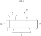
- FIG. 2 illustrates a top plan view schematically showing the complex minute cutting apparatus of FIG. 1
- FIG. 3 illustrates a cross-sectional view of main parts schematically showing the complex minute cutting apparatus of FIG. 1 .
- the complex minute cutting apparatus for a superabsorbent hydrogel includes a barrel body 10 in which a transfer space 11 through which a hydrogel is transferred is formed, a transfer unit 20 installed in the barrel body 10 to transfer the hydrogel in the transfer space 11, and a plurality of cutting modules 30 installed in the transfer unit 20 to pulverize the hydrogel and discharge the pulverized hydrogel to the outside of the barrel body 10 in a cut state.
- the barrel body 10 may be installed in a state in which the transfer space 11 through which the hydrogel is transferred is formed along a longitudinal direction and supported on a bottom surface thereof.
- An injection part 12 for injecting the hydrogel into the transfer space 11 may be installed in an open state at an upper portion of the barrel body 10.
- a support base 13 may protrude from a lower portion of the barrel body 10 for being stably supported on the bottom surface thereof.
- a barrel spiral 15 may protrude inside the barrel body 10.
- the barrel spiral 15 may be formed to protrude from an inner wall surface of the barrel body 10 in a spiral shape corresponding to a spiral shape of a screw member 21.
- the barrel spiral 15 may be formed to protrude from the inner wall surface of the barrel body 10 in a plurality of spiral shapes in an opposite direction corresponding to the spiral shape of the screw member 21.
- the barrel spiral 15 is exemplarily described to protrude from the inner wall surface of the barrel body 10, but the present invention is not limited thereto, and it may not be formed.
- the barrel spiral 15 is not necessarily limited to the spiral shape, but may have a concentric band-shaped protrusion on the inner wall surface of the barrel body 10 or a sphere protruding corresponding to a helical position of the screw member 21, or it is also possible to apply various changes such as angular protrusion.
- the hydrogel may be stably transferred without backflow together with auxiliary action of the hydrogel.
- the hydrogel may be transferred by a transfer operation of the transfer unit 20, which will be described later, in a state of being injected into the barrel body 10 through the injection part 12.
- the injection part 12 is formed in an open state at an upper side of the barrel body 10, and is installed in a state expanded upward, so that the hydrogel may be easily introduced into the inside.
- the hydrogel may be appropriately pulverized by being transferred in a direction of a discharge part 14 of the barrel body 10 by a driving force of the transfer unit 20 in the state of being injected into the inside of the barrel body 10.
- the transfer unit 20, which is installed in the barrel body 10, may be installed to provide a transfer driving force for transferring the hydrogel.
- the transfer unit 20 includes a screw member 21 that is rotatably installed in the transfer space 11 to move the hydrogel, and a driving motor 23 that provides a rotational driving force to the screw member 21.
- the screw member 21, which is rotatably installed along the longitudinal direction of the transfer space 11 inside the barrel body 10, may be installed to transfer the hydrogel filled in the transfer space 11 by a driving operation of the driving motor 23 in a direction of the discharge part 14 of the barrel body 10.
- the driving motor 23 may be installed in the barrel body 10, and a driving shaft may be installed at a first end of the screw member 21 to provide a rotational driving force by rotating the screw member 21 in one direction such that the hydrogel is transferred inside the barrel body 10 while maintaining an appropriate transferring speed.
- the driving motor 23 and the screw member 21 may be installed to transfer the rotational driving force through a reducer (not illustrated).
- a cutting module 30 may be installed in the screw member 21 for discharging the hydrogel to the outside of the discharging part 14 in a cut state by pulverizing the hydrogel.
- a plurality of cutting modules 30 may be installed along a longitudinal direction of the screw member 21.
- a reason why the cutting modules 30 are installed in the screw member 21 is to maintain a size of cut particles of the hydrogel at an appropriate level to enable smooth cutting.
- each cutting module 30 may include a cutter member 31 installed inside the barrel body 10 to pulverize the hydrogel transferred by the transfer unit 20, and a perforated plate 33 for discharging the hydrogel pulverized by the cutter member 31 in a cut state.
- the cutting modules 30 may be installed to be spaced apart from each other along the longitudinal direction of the screw member 21.
- the cutter member 31 may be rotatably installed together with the rotational operation of the screw member 21 to appropriately pulverize the hydrogel transferred from the transfer space 11 by the screw member 21.
- a plurality of cutter members 31 may be installed in the screw member 21 with the perforated plate 33 interposed therebetween.
- the perforated plate 33 may be installed between the cutter members 31 and at a portion of the discharge part 14 of the barrel body 10, respectively.
- a plurality of cutting holes may be formed in the perforated plate 33.
- the hydrogel pulverized by the cutter member 31 may be pressed and moved inside the barrel body 10 by a pressing force generated by a rotational operation of the screw member 21, thereby being stably discharged in the cut state through the cutting holes of the perforated plate 33.
- a surfactant may be injected into the barrel body 10.
- the surfactant may allow a smoother cutting action in the process of pulverizing the hydrogel in the perforated plate 33 and cutting it through the cutting holes of the perforated plate 33.
- the perforated plate 33 may be formed of a heat-treated metal material to stably support a pressing force of the transferred hydrogel.
- FIG. 4 illustrates main parts schematically showing a state in which a plurality of perforated plates are installed in a barrel body according to the first embodiment of the present invention.
- FIG. 4 illustrates main parts schematically showing only the perforated plate 33 installed inside the barrel body 10.
- a plurality of perforated plates 33 are disposed in a state of being spaced apart from each other at a predetermined interval along the longitudinal direction of the screw member 21, and cutting holes 33a may be formed in a state in which a diameter of each of the plurality of perforated plates 33 is gradually decreased in the direction of the discharge part 14.
- the cutting holes 33a may be formed to have a maximum diameter in the perforated plate 33 at a position A closest to the driving motor 23 from the inside of the barrel body 10, and may be formed to have a minimum diameter at the perforated plate 33 at a position B closest to the discharge part 14.
- the perforated plates 33 and the cutter members 31 are installed along the longitudinal direction of the screw member 21, and the size of the cutting holes 33a formed in each of the perforated plates 33 is gradually reduced in the direction of the discharge unit 14, so that the cutting process of the hydrogel may be more smoothly performed and the hydrogel may be cut to have a small size of several millimeters or less.
- Example 1 a monomer composition having a total solid content of 45.0 wt% was prepared by mixing 100 g of acrylic acid (acrylic acid), 123.5 g of 32 % caustic soda (NaOH), 0.2 g of sodium persulfate as a thermal polymerization initiator, 0.008 g of phenyl (2,4,6 trimethylbenzoyl) phosphine oxide as a photoinitiator, 0.26 g of polyethylene glycol diacrylate (PEGDA), and 40 g of water.
- acrylic acid acrylic acid
- NaOH caustic soda
- NaOH sodium persulfate
- sodium persulfate sodium persulfate
- phenyl (2,4,6 trimethylbenzoyl) phosphine oxide as a photoinitiator
- PEGDA polyethylene glycol diacrylate
- a polymerization reaction was carried out for 60 s by supplying a monomer composition to an ultraviolet irradiation device, and at the same time, by irradiating ultraviolet rays having an intensity of 10 mW/cm 2 .
- a final hydrogel sample was obtained by applying 0.3 g of a hydrophobic surfactant (SPAN 60) to a polymerization sheet manufactured after the polymerization reaction was performed, and then performing cutting by using a chopper with equally spaced screws, and drying it by using a rotary dryer with a speed of 300RPM.
- SPAN 60 hydrophobic surfactant
- Example 2 Comparative Example 2 Hole plate size 6 6 Additive used SA SA Additive amount used (ppm) 3000 3000 Polymerization sheet temperature (°C) 80 40 CRC 30.4 Cannot be manufactured and measured due to severe kneading EC 5.5 BPI 23.0
- CRC centrifugal retention capacity
- EC extractable content
- FIG. 5 illustrates a poor state of a cut state of a hydrogel 110 when the temperature of the polymerization sheet is 40 °C
- FIG. 6 illustrates a state in which kneading does not occur in the hydrogel 110 when the temperature of the polymerization sheet is 80 °C.
- FIG. 7 illustrates main parts schematically showing a state in which pitches of a screw member are formed at an equal interval according to a third embodiment of the present invention. Detailed descriptions of the same reference numerals as those of FIG. 1 to FIG. 6 are omitted.
- a pitch P of the screw member 121 according to the third embodiment of the present invention may be formed to protrude at equal pitches at an equal interval. Accordingly, the cut particles of the hydrogel may be cut in a good state without kneading.
- Table 3 shows a process of cutting the hydrogel using the screw member having equal pitches at an equal interval with a general screw according to the third embodiment.
- Table 3 Existing general screw member Screw member with equal pitches Hole plate size (mm) 6 6 Additive used Span 60 Span 60 Additive amount used (ppm) 3000 3000 CRC 31.5 30.1 EC 6.3 4.1 BPI 21.8 27.5
- FIG. 8 illustrates an enlarged view of main parts showing particles of a hydrogel that is cut by using a conventional screw member
- FIG. 9 illustrates an enlarged view of main parts showing minutely set particles of a hydrogel using a screw member having equally spaced pitches according to a fourth embodiment of the present invention.
Landscapes
- Engineering & Computer Science (AREA)
- Mechanical Engineering (AREA)
- Life Sciences & Earth Sciences (AREA)
- Forests & Forestry (AREA)
- Chemical & Material Sciences (AREA)
- Food Science & Technology (AREA)
- Chemical Kinetics & Catalysis (AREA)
- Medicinal Chemistry (AREA)
- Polymers & Plastics (AREA)
- Organic Chemistry (AREA)
- Health & Medical Sciences (AREA)
- Addition Polymer Or Copolymer, Post-Treatments, Or Chemical Modifications (AREA)
- Processes Of Treating Macromolecular Substances (AREA)
- Perforating, Stamping-Out Or Severing By Means Other Than Cutting (AREA)
Abstract
Description
- This application claims priority to and the benefit of
Korean Patent Application No. 10-2019-0150705, filed in the Korean Intellectual Property Office on 11/21/2019 - The present invention relates to a complex minute cutting apparatus for a superabsorbent hydrogel, capable of performing smooth minute cutting of the hydrogel.
- A superabsorbent polymer (SAP) is a synthetic polymer material with a function of being capable of absorbing moisture of 500 to 1000 times its own weight, and is referred to as a superabsorbency material (SAM), an absorbent gel material (AGM), or the like by each developer.
- The above-described superabsorbent polymer has begun to be put into practical use as a sanitary product, and is currently widely used as a material such as a soil repair agent for gardening, a water supply material for civil works or construction, a sheet for seedlings, a freshness maintenance agent in the food distribution field, and a material for a poultice in addition to hygiene products such as paper diapers for children.
- As a method of preparing the superabsorbent polymer as described above, a method by reverse-phase suspension polymerization or a method by aqueous solution polymerization is known. Regarding reverse-phase suspension polymerization, for example,
Japanese Patent Publication No. 56-161408 Japanese Patent Publication No. 57-158209 Japanese Patent Publication No. 57-198714 - A hydrogel or hydrogel polymer obtained through the polymerization reaction as described above is generally pulverized after a drying process and then is commercially available as a powdery product. It is important to increase the surface area of the hydrogel polymer as much as possible in order to efficiently perform the drying step. Accordingly, a method of increasing a surface area of the hydrogel polymer to be dried by simply pulverizing the hydrogel polymer that is polymerized through thermal polymerization or photopolymerization may be considered in order to increase the surface area of the hydrogel polymer before the drying process as much as possible. A process of first pulverizing the hydrogel polymer after polymerization has been disclosed in order to increase the surface area of the hydrogel polymer as described above.
- A chopper is mainly used in the first pulverizing the hydrogel polymer.
- Such a chopper includes a screw for moving the hydrogel, a barrel including a spiral, a cutter blade for cutting the hydrogel, and a perforated plate from which the cut hydrogel is discharged.
- Herein, the cutter blade and the perforated plate are each installed as a single unit, and thus it is difficult to cut it into a particle size of the hydrogel to be equal to or smaller than a predetermined size. In addition, even when the particle size is cut below a predetermined size by repeating the cutting process, the gel cut into a very small particle size may cause a kneading phenomenon by increasing a pressure in the chopper, resulting in an increase in an extractable content (EC) and a change in a physical property.
- An embodiment of the present invention has been made in an effort to provide a complex minute cutting apparatus for a superabsorbent hydrogel, capable of performing a cutting process of the hydrogel into a small size that is equal to or smaller than a predetermined size and improving manufacturing quality.
- An embodiment of the present invention provides a complex minute cutting apparatus for a superabsorbent hydrogel, including: a barrel body in which a transfer space through which a hydrogel is transferred is formed and a discharge part is formed at a side surface thereof; a transfer unit installed in the barrel body to transfer the hydrogel in the transfer space; and a plurality of cutting modules installed in the transfer unit to pulverize the hydrogel and discharging it to an outside of the discharge unit in a cut state.
- Each of cutting modules may include: a cutter member installed inside the barrel body to pulverize the hydrogel transferred by the transfer unit; and perforated plates configured to discharge the hydrogel pulverized by the cutter member in a cut state.
- The transfer unit may include: a screw member rotatably installed in the transfer space to move the hydrogel; and a driving motor configured to provide a rotational driving force to the screw member.
- The cutting modules may be installed in a state of being spaced apart from each other in a direction of the discharge part in the screw member.
- A plurality of cutting holes for discharging the hydrogel in a cut state may be formed in the perforated plates, and the cutting holes may be formed in the perforated plates to have diameters of different sizes.
- The cutting holes may be formed to have a minimum diameter at a position of the discharge part among the perforated plates.
- Screw threads of the screw member may be formed to have a same pitch.
- According to an embodiment of the present invention, a smooth cutting process of a hydrogel and smooth cutting of the hydrogel into a small size of less than a predetermined size are possible by installing a perforated plate and a cutter member and forming a size of cutting holes formed in each of a plurality of perforated plates to gradually decrease in a direction of a discharge part.
-
-
FIG. 1 illustrates a schematic perspective view of a complex minute cutting apparatus for a superabsorbent hydrogel according to a first embodiment of the present invention. -
FIG. 2 illustrates a top plan view schematically showing the complex minute cutting apparatus ofFIG. 1 . -
FIG. 3 illustrates a cross-sectional view of main parts schematically showing the complex minute cutting apparatus ofFIG. 1 . -
FIG. 4 illustrates main parts schematically showing a state in which a plurality of perforated plates are installed in a barrel body according to the first embodiment of the present invention. -
FIG. 5 schematically illustrates a cutting state of a conventional hydrogel at a temperature of 40 °C. -
FIG. 6 schematically illustrates a cutting state of a hydrogel at a temperature of 80 °C according to a first embodiment of the present invention. -
FIG. 7 illustrates main parts schematically showing a state in which pitches of a screw member are formed at an equal interval according to a third embodiment of the present invention. -
FIG. 8 illustrates an enlarged view of main parts schematically showing particles of a hydrogel that is cut by using a conventional screw member. -
FIG. 9 illustrates an enlarged view of main parts showing minutely set particles of a hydrogel using a screw member having equally spaced pitches according to a fourth embodiment of the present invention. - Hereinafter, the present invention will be described more fully with reference to the accompanying drawings, in which exemplary embodiments of the invention are shown. As those skilled in the art would realize, the described embodiments may be modified in various different ways, all without departing from the scope of the present invention. The drawings and description are to be regarded as illustrative in nature and not restrictive. Like reference numerals designate like elements throughout the specification.
-
FIG. 1 illustrates a schematic perspective view of a complex minute cutting apparatus for a superabsorbent hydrogel according to a first embodiment of the present invention,FIG. 2 illustrates a top plan view schematically showing the complex minute cutting apparatus ofFIG. 1 , andFIG. 3 illustrates a cross-sectional view of main parts schematically showing the complex minute cutting apparatus ofFIG. 1 . - As illustrated in
FIG. 1 to FIG. 3 , according to the first example of the present invention, the complex minute cutting apparatus for a superabsorbent hydrogel includes abarrel body 10 in which a transfer space 11 through which a hydrogel is transferred is formed, atransfer unit 20 installed in thebarrel body 10 to transfer the hydrogel in the transfer space 11, and a plurality ofcutting modules 30 installed in thetransfer unit 20 to pulverize the hydrogel and discharge the pulverized hydrogel to the outside of thebarrel body 10 in a cut state. - The
barrel body 10 may be installed in a state in which the transfer space 11 through which the hydrogel is transferred is formed along a longitudinal direction and supported on a bottom surface thereof. - An
injection part 12 for injecting the hydrogel into the transfer space 11 may be installed in an open state at an upper portion of thebarrel body 10. - A
support base 13 may protrude from a lower portion of thebarrel body 10 for being stably supported on the bottom surface thereof. - A barrel spiral 15 may protrude inside the
barrel body 10. - The barrel spiral 15 may be formed to protrude from an inner wall surface of the
barrel body 10 in a spiral shape corresponding to a spiral shape of ascrew member 21. - The barrel spiral 15 may be formed to protrude from the inner wall surface of the
barrel body 10 in a plurality of spiral shapes in an opposite direction corresponding to the spiral shape of thescrew member 21. - In the present embodiment, the barrel spiral 15 is exemplarily described to protrude from the inner wall surface of the
barrel body 10, but the present invention is not limited thereto, and it may not be formed. - The barrel spiral 15 is not necessarily limited to the spiral shape, but may have a concentric band-shaped protrusion on the inner wall surface of the
barrel body 10 or a sphere protruding corresponding to a helical position of thescrew member 21, or it is also possible to apply various changes such as angular protrusion. - As such, since he barrel spiral 15 is formed to protrude inside the
barrel body 10, the hydrogel may be stably transferred without backflow together with auxiliary action of the hydrogel. - The hydrogel may be transferred by a transfer operation of the
transfer unit 20, which will be described later, in a state of being injected into thebarrel body 10 through theinjection part 12. - The
injection part 12 is formed in an open state at an upper side of thebarrel body 10, and is installed in a state expanded upward, so that the hydrogel may be easily introduced into the inside. - As such, the hydrogel may be appropriately pulverized by being transferred in a direction of a
discharge part 14 of thebarrel body 10 by a driving force of thetransfer unit 20 in the state of being injected into the inside of thebarrel body 10. - The
transfer unit 20, which is installed in thebarrel body 10, may be installed to provide a transfer driving force for transferring the hydrogel. - More specifically, the
transfer unit 20 includes ascrew member 21 that is rotatably installed in the transfer space 11 to move the hydrogel, and a drivingmotor 23 that provides a rotational driving force to thescrew member 21. - The
screw member 21, which is rotatably installed along the longitudinal direction of the transfer space 11 inside thebarrel body 10, may be installed to transfer the hydrogel filled in the transfer space 11 by a driving operation of the drivingmotor 23 in a direction of thedischarge part 14 of thebarrel body 10. - The driving
motor 23 may be installed in thebarrel body 10, and a driving shaft may be installed at a first end of thescrew member 21 to provide a rotational driving force by rotating thescrew member 21 in one direction such that the hydrogel is transferred inside thebarrel body 10 while maintaining an appropriate transferring speed. - The driving
motor 23 and thescrew member 21 may be installed to transfer the rotational driving force through a reducer (not illustrated). - Meanwhile, a
cutting module 30 may be installed in thescrew member 21 for discharging the hydrogel to the outside of thedischarging part 14 in a cut state by pulverizing the hydrogel. - A plurality of
cutting modules 30 may be installed along a longitudinal direction of thescrew member 21. - A reason why the cutting
modules 30 are installed in thescrew member 21 is to maintain a size of cut particles of the hydrogel at an appropriate level to enable smooth cutting. - More specifically, each cutting
module 30 may include acutter member 31 installed inside thebarrel body 10 to pulverize the hydrogel transferred by thetransfer unit 20, and aperforated plate 33 for discharging the hydrogel pulverized by thecutter member 31 in a cut state. The cuttingmodules 30 may be installed to be spaced apart from each other along the longitudinal direction of thescrew member 21. - The
cutter member 31 may be rotatably installed together with the rotational operation of thescrew member 21 to appropriately pulverize the hydrogel transferred from the transfer space 11 by thescrew member 21. - Since the cutting
modules 30 are installed, a plurality ofcutter members 31 may be installed in thescrew member 21 with theperforated plate 33 interposed therebetween. - The
perforated plate 33 may be installed between thecutter members 31 and at a portion of thedischarge part 14 of thebarrel body 10, respectively. A plurality of cutting holes may be formed in theperforated plate 33. - Accordingly, the hydrogel pulverized by the
cutter member 31 may be pressed and moved inside thebarrel body 10 by a pressing force generated by a rotational operation of thescrew member 21, thereby being stably discharged in the cut state through the cutting holes of theperforated plate 33. - Herein, a surfactant may be injected into the
barrel body 10. The surfactant may allow a smoother cutting action in the process of pulverizing the hydrogel in theperforated plate 33 and cutting it through the cutting holes of theperforated plate 33. - The
perforated plate 33 may be formed of a heat-treated metal material to stably support a pressing force of the transferred hydrogel. -
FIG. 4 illustrates main parts schematically showing a state in which a plurality of perforated plates are installed in a barrel body according to the first embodiment of the present invention. - As illustrated in
FIG. 4 , the cuttingholes 33a formed in theperforated plate 33 may be formed in each of the plurality ofperforated plates 33 to have different diameters.FIG. 4 illustrates main parts schematically showing only theperforated plate 33 installed inside thebarrel body 10. - That is, a plurality of
perforated plates 33 are disposed in a state of being spaced apart from each other at a predetermined interval along the longitudinal direction of thescrew member 21, and cuttingholes 33a may be formed in a state in which a diameter of each of the plurality ofperforated plates 33 is gradually decreased in the direction of thedischarge part 14. - As such, among the plurality of
perforated plates 33, the cuttingholes 33a may be formed to have a maximum diameter in theperforated plate 33 at a position A closest to the drivingmotor 23 from the inside of thebarrel body 10, and may be formed to have a minimum diameter at theperforated plate 33 at a position B closest to thedischarge part 14. - As described above, in the complex
minute cutting apparatus 100 for a superabsorbent hydrogel, theperforated plates 33 and thecutter members 31 are installed along the longitudinal direction of thescrew member 21, and the size of the cuttingholes 33a formed in each of theperforated plates 33 is gradually reduced in the direction of thedischarge unit 14, so that the cutting process of the hydrogel may be more smoothly performed and the hydrogel may be cut to have a small size of several millimeters or less. - According to Example 1, a monomer composition having a total solid content of 45.0 wt% was prepared by mixing 100 g of acrylic acid (acrylic acid), 123.5 g of 32 % caustic soda (NaOH), 0.2 g of sodium persulfate as a thermal polymerization initiator, 0.008 g of phenyl (2,4,6 trimethylbenzoyl) phosphine oxide as a photoinitiator, 0.26 g of polyethylene glycol diacrylate (PEGDA), and 40 g of water.
- Herein, a polymerization reaction was carried out for 60 s by supplying a monomer composition to an ultraviolet irradiation device, and at the same time, by irradiating ultraviolet rays having an intensity of 10 mW/cm2. A final hydrogel sample was obtained by applying 0.3 g of a hydrophobic surfactant (SPAN 60) to a polymerization sheet manufactured after the polymerization reaction was performed, and then performing cutting by using a chopper with equally spaced screws, and drying it by using a rotary dryer with a speed of 300RPM.
-
(Table 1) 4 mm hole plate (perforated plate) Mesh Period Particle size 1 time 2 times 3 times 5 times 7 times 9 times 11 times 13 times # 10 more 3000 55 23 5 2 0 0 0 1 #10-14 1700 24 28 22 13 5 3 3 3 # 14-20 1125 15 26 39 38 29 26 24 21 #20-30 725 4 11 19 24 26 28 28 25 #30-50 450 2 10 14 22 34 38 41 43 #50-100 225 0 2 1 2 5 4 4 6 # 100 less 75 0 0 0 0 1 1 0 0 Average particle size (µm) 2272 1590 1162 962 783 730 718 710 Particle size reduction rate 100 % 70% 51 % 42 % 34% 32 % 32 % 31 % - As shown in Table 1, it can be seen that the average particle size decreases when the hydrogel is passed through the
perforated plate 13 times, and the average particle size decreases during cutting of the hydrogel when the hydrogel of Example 1 is passed through a plurality of perforated plates through Comparative Example 1. - As shown in Table 2, it can be seen that a type of the hydrophobic surfactant of Example 1 was changed to SA (stearic acid series), and in the comparative example, the temperature of the cutting process was changed to 40 °C, and it is impossible to manufacture and measure it due to severe kneading at 40 °C.
(Table 2) Example 2 Comparative Example 2 Hole plate size 6 6 Additive used SA SA Additive amount used (ppm) 3000 3000 Polymerization sheet temperature (°C) 80 40 CRC 30.4 Cannot be manufactured and measured due to severe kneading EC 5.5 BPI 23.0 - In Table 2, CRC denotes centrifugal retention capacity, and EC denotes an extractable content.
-
FIG. 5 illustrates a poor state of a cut state of ahydrogel 110 when the temperature of the polymerization sheet is 40 °C, andFIG. 6 illustrates a state in which kneading does not occur in thehydrogel 110 when the temperature of the polymerization sheet is 80 °C. -
FIG. 7 illustrates main parts schematically showing a state in which pitches of a screw member are formed at an equal interval according to a third embodiment of the present invention. Detailed descriptions of the same reference numerals as those ofFIG. 1 to FIG. 6 are omitted. - As illustrated in
FIG. 7 , a pitch P of thescrew member 121 according to the third embodiment of the present invention may be formed to protrude at equal pitches at an equal interval. Accordingly, the cut particles of the hydrogel may be cut in a good state without kneading. - Table 3 shows a process of cutting the hydrogel using the screw member having equal pitches at an equal interval with a general screw according to the third embodiment.
(Table 3) Existing general screw member Screw member with equal pitches Hole plate size (mm) 6 6 Additive used Span 60 Span 60 Additive amount used (ppm) 3000 3000 CRC 31.5 30.1 EC 6.3 4.1 BPI 21.8 27.5 -
FIG. 8 illustrates an enlarged view of main parts showing particles of a hydrogel that is cut by using a conventional screw member, andFIG. 9 illustrates an enlarged view of main parts showing minutely set particles of a hydrogel using a screw member having equally spaced pitches according to a fourth embodiment of the present invention. - As illustrated in
FIG. 8 , it can be seen that kneading occurs in ahydrogel 210 in the conventional screw member, while as illustrated inFIG. 9 , kneading does not occur in thehydrogel 210 in the fourth embodiment of the present invention. In addition, as shown in Table 3, an effect of reducing EC may be confirmed. - That is, as illustrated in
FIG. 9 , in the case of using screw members with equally spaced pitches, pressure drop occurs, so kneading of hydrogel particles does not occur, and an effect of reducing extractable content (EC) is also possible. - While this invention has been described in connection with what is presently considered to be practical exemplary embodiments, it is to be understood that the invention is not limited to the disclosed embodiments, but, on the contrary, is intended to cover various modifications and equivalent arrangements included within the scope of the appended claims.
Description of Symbols 10 barrel body 11 transfer space 12 injection part 13 support base 14 discharge part 15 barrel spiral 20 transfer unit 21, 121 screw member 23 driving motor 30 cutting module 31 cutter member 33 perforated plate 33a cutting hole 110, 210 hydrogel
Claims (7)
- A complex minute cutting apparatus for a superabsorbent hydrogel, comprising:a barrel body comprising: a transfer space through which a hydrogel is transferred; and a discharge part at a side surface of the barrel body;a transfer unit located in the transfer space of the barrel body and configured to transfer the hydrogel in the transfer space; anda plurality of cutting modules attached to the transfer unit and configured to pulverize and discharge the hydrogel through a discharge part in a particle form.
- The complex minute cutting apparatus of claim 1, wherein
each of the cutting modules includes:a cutter member configured to pulverize the hydrogel transferred by the transfer unit; andperforated plates configured to discharge the hydrogel pulverized by the cutter member in a cut state. - The complex minute cutting apparatus of claim 2, wherein
the transfer unit includes:a screw member which rotates in the transfer space to move the hydrogel; anda driving motor configured to provide a rotational driving force to the screw member. - The complex minute cutting apparatus of claim 3, wherein
the plurality of cutting modules are arranged spaced apart from each other towards the discharge part. - The complex minute cutting apparatus of claim 4, whereinthe perforated plates comprise a plurality of cutting holes for discharging the hydrogel in a particle form, andthe cutting holes are formed in the perforated plates to have diameters of different sizes.
- The complex minute cutting apparatus of claim 5, wherein
the perforated plate located at a closest position to the discharge part has the cutting holes having a smallest diameter. - The complex minute cutting apparatus of claim 3, wherein
the screw member comprises a plurality of screw threads having a same pitch.
Applications Claiming Priority (2)
| Application Number | Priority Date | Filing Date | Title |
|---|---|---|---|
| KR1020190150705A KR20210062459A (en) | 2019-11-21 | 2019-11-21 | Complex minute cutting apparatus for super absorbent polymer hydrous gel |
| PCT/KR2020/016390 WO2021101277A1 (en) | 2019-11-21 | 2020-11-19 | Composite chopper for superabsorbent hydrogel |
Publications (2)
| Publication Number | Publication Date |
|---|---|
| EP3984711A1 true EP3984711A1 (en) | 2022-04-20 |
| EP3984711A4 EP3984711A4 (en) | 2022-08-24 |
Family
ID=75981376
Family Applications (1)
| Application Number | Title | Priority Date | Filing Date |
|---|---|---|---|
| EP20889315.6A Pending EP3984711A4 (en) | 2019-11-21 | 2020-11-19 | COMPOSITE CHOPPER FOR SUPERABSORBENT HYDROGEL |
Country Status (8)
| Country | Link |
|---|---|
| US (1) | US12251856B2 (en) |
| EP (1) | EP3984711A4 (en) |
| JP (1) | JP7335050B2 (en) |
| KR (1) | KR20210062459A (en) |
| CN (1) | CN114096388B (en) |
| BR (1) | BR112022001362A2 (en) |
| MY (1) | MY209979A (en) |
| WO (1) | WO2021101277A1 (en) |
Cited By (5)
| Publication number | Priority date | Publication date | Assignee | Title |
|---|---|---|---|---|
| EP4000736A4 (en) * | 2019-10-18 | 2022-09-14 | LG Chem, Ltd. | SUPER ABSORBENT POLYMER HYDROGEL GRINDER USING A PUMP |
| EP4011576A4 (en) * | 2020-02-28 | 2022-12-07 | LG Chem, Ltd. | SUPERABSORBENT POLYMER HYDROGEL Chopper |
| EP4197639A4 (en) * | 2021-06-18 | 2024-01-24 | Lg Chem, Ltd. | MICRONIZATION DEVICE FOR HYDROGEL MADE OF SUPERABSORBENT POLYMER |
| US12491662B2 (en) | 2019-10-18 | 2025-12-09 | Lg Chem, Ltd. | Minute cutting apparatus for super absorbent polymer hydrogel using pump |
| US12521726B2 (en) | 2021-06-18 | 2026-01-13 | Lg Chem, Ltd. | Micronizing apparatus for hydrogel of super absorbent polymer |
Families Citing this family (9)
| Publication number | Priority date | Publication date | Assignee | Title |
|---|---|---|---|---|
| EP4209535A4 (en) * | 2021-06-18 | 2024-04-03 | Lg Chem, Ltd. | METHOD FOR PREPARING A SUPERABSORBENT POLYMER |
| JP7493862B2 (en) * | 2021-06-18 | 2024-06-03 | エルジー・ケム・リミテッド | Manufacturing method of superabsorbent resin |
| WO2022265459A1 (en) * | 2021-06-18 | 2022-12-22 | 주식회사 엘지화학 | Method for preparing super absorbent polymer, and super absorbent polymer |
| JP7708499B2 (en) * | 2021-06-18 | 2025-07-15 | エルジー・ケム・リミテッド | Method for producing superabsorbent polymer and superabsorbent polymer |
| US20230338925A1 (en) * | 2021-06-18 | 2023-10-26 | Lg Chem, Ltd. | Micronizing apparatus for hydrogel of super absorbent polymer |
| EP4173717A4 (en) * | 2021-06-18 | 2024-01-17 | Lg Chem, Ltd. | MICRONIZATION DEVICE FOR SUPERABSORBENT POLYMER HYDROGEL |
| CN113580411A (en) * | 2021-08-05 | 2021-11-02 | 徐州莫大新材料科技有限公司 | Grain device is cut to polymer water absorption gel material that keeps water |
| JP7726601B2 (en) * | 2021-10-29 | 2025-08-20 | エルジー・ケム・リミテッド | Highly water-absorbent resin composition and method for producing the same |
| KR20230119475A (en) * | 2022-02-07 | 2023-08-16 | 주식회사 엘지화학 | Micronizing apparatus for hydrogel of super absorbent polymer |
Family Cites Families (38)
| Publication number | Priority date | Publication date | Assignee | Title |
|---|---|---|---|---|
| JPS5432176B2 (en) * | 1973-05-02 | 1979-10-12 | ||
| US4003521A (en) * | 1975-05-27 | 1977-01-18 | Speco, Inc. | Dual-phase meat grinder adapter |
| JPS56161408A (en) | 1980-05-19 | 1981-12-11 | Kao Corp | Production of water-absorbing resin |
| JPS57158209A (en) | 1981-03-25 | 1982-09-30 | Kao Corp | Production of bead-form highly water-absorbing polymer |
| JPS57198714A (en) | 1981-05-29 | 1982-12-06 | Sumitomo Chem Co Ltd | Production of hydrogel |
| JPS6291251A (en) * | 1985-10-16 | 1987-04-25 | 株式会社 平賀工作所 | Cutter for chopper |
| JPS62286559A (en) * | 1986-06-04 | 1987-12-12 | 株式会社 平賀工作所 | Chopper |
| JPS62286560A (en) * | 1986-06-04 | 1987-12-12 | 株式会社 平賀工作所 | Chopper |
| US4844372A (en) * | 1988-07-11 | 1989-07-04 | Weiler And Company, Inc | Double plate retrofit assembly for a meat grinder |
| US5704555A (en) * | 1993-08-02 | 1998-01-06 | Illinois Institute Of Technology | Single-screw extruder for solid state shear extrusion pulverization and method |
| JP3415036B2 (en) * | 1998-08-12 | 2003-06-09 | 株式会社日本触媒 | Method for granulating hydrogel crosslinked polymer |
| JP4132592B2 (en) * | 1999-06-25 | 2008-08-13 | 株式会社日本触媒 | Water absorbent resin and method for producing the same |
| EP1510317B1 (en) * | 2003-09-01 | 2007-02-21 | Nippon Shokubai Co., Ltd. | Process for production of water-absorbent resin particles from hydrogel particles |
| EP2052773B1 (en) | 2004-09-28 | 2012-07-18 | Basf Se | Kneader and use of the kneader for producing poly(meth)acrylates |
| KR100682023B1 (en) | 2005-06-11 | 2007-02-15 | 여인봉 | Livestock waste treatment method and apparatus |
| US9593212B2 (en) * | 2006-09-29 | 2017-03-14 | Nippon Shokubai Co., Ltd. | Method for producing water absorbent resin particle |
| DE102007025899B4 (en) * | 2007-06-01 | 2011-03-03 | Inotec Gmbh Maschinenentwicklung Und Vertrieb | Device for crushing a comminuted material |
| KR101367362B1 (en) | 2010-03-19 | 2014-02-26 | 주식회사 엘지화학 | Polymerization reactor and preparation method of super absorbent polymer |
| KR101367361B1 (en) | 2010-06-16 | 2014-02-26 | 주식회사 엘지화학 | Polymerization reactor for super adsorbent polymer and preparation method of super adsorbent polymer |
| CN102824878A (en) | 2011-06-16 | 2012-12-19 | 张家港市贝尔机械有限公司 | Granulation extruder with cylinder which requires no heating |
| WO2014033083A1 (en) | 2012-08-29 | 2014-03-06 | Basf Se | Process for producing water-absorbing polymer particles |
| JP6170996B2 (en) * | 2013-02-15 | 2017-07-26 | 株式会社大貴 | Separation apparatus and separation method |
| EP3040362B1 (en) | 2013-08-28 | 2018-08-08 | Nippon Shokubai Co., Ltd. | Gel pulverization device, and related method for manufacturing superabsorbent polymer powder |
| CN109608661B (en) | 2013-08-28 | 2021-09-10 | 株式会社日本触媒 | Gel crushing device, method for producing polyacrylic acid (salt) -based water-absorbent resin powder, and water-absorbent resin powder |
| CN106715543B (en) | 2014-09-29 | 2020-10-30 | 株式会社日本触媒 | Water-absorbent resin powder and method for measuring elastic modulus of water-absorbent resin powder |
| KR20160078114A (en) * | 2014-12-24 | 2016-07-04 | 한화케미칼 주식회사 | Chopper for manufacturing super absorbent polymer and method for manufacturing super absorbent polymer using the same |
| EP3398977B1 (en) | 2015-12-28 | 2022-12-14 | Nippon Shokubai Co., Ltd. | Method for producing water absorbent resin |
| CN110300650B (en) | 2016-12-21 | 2022-01-21 | 巴斯夫欧洲公司 | Single-shaft extruder and method for changing gel form of super absorbent polymer by using same |
| CN206472524U (en) | 2017-01-24 | 2017-09-08 | 慈溪市隆诚贸易有限公司 | Roller pulverizer |
| CN206519221U (en) | 2017-02-07 | 2017-09-26 | 湖州吉能生物质燃料有限公司 | A kind of straw millstone for straw granulating |
| KR102518937B1 (en) | 2017-12-22 | 2023-04-05 | 주식회사 엘지화학 | Method for Preparing Super Absorbent Polymer |
| CN208066469U (en) | 2018-01-10 | 2018-11-09 | 南通市肺科医院(南通市第六人民医院) | A kind of Pharmacy's medicine crushing device |
| CN208302929U (en) * | 2018-02-02 | 2019-01-01 | 廊坊瑞康饲料有限公司 | Feed crushes processing unit (plant) |
| CN108311236A (en) * | 2018-03-30 | 2018-07-24 | 安吉艺科装饰材料科技有限公司 | A kind of raw material grinding device with screening function |
| KR102457690B1 (en) | 2019-01-17 | 2022-10-21 | 주식회사 엘지화학 | Super absorbent polymer and preparation method of the same |
| WO2020149691A1 (en) | 2019-01-17 | 2020-07-23 | 주식회사 엘지화학 | Super absorbent polymer and preparation method therefor |
| BR112021022743A2 (en) | 2019-09-19 | 2022-01-11 | Lg Chemical Ltd | Superabsorbent hydrogel polymer fragmentation device |
| CN114340798B (en) | 2019-10-18 | 2023-10-31 | 株式会社Lg化学 | Fine cutting device for superabsorbent polymer hydrogel using pump |
-
2019
- 2019-11-21 KR KR1020190150705A patent/KR20210062459A/en not_active Ceased
-
2020
- 2020-11-19 BR BR112022001362A patent/BR112022001362A2/en unknown
- 2020-11-19 CN CN202080050463.2A patent/CN114096388B/en active Active
- 2020-11-19 US US17/630,576 patent/US12251856B2/en active Active
- 2020-11-19 MY MYPI2022000029A patent/MY209979A/en unknown
- 2020-11-19 EP EP20889315.6A patent/EP3984711A4/en active Pending
- 2020-11-19 JP JP2022500712A patent/JP7335050B2/en active Active
- 2020-11-19 WO PCT/KR2020/016390 patent/WO2021101277A1/en not_active Ceased
Cited By (6)
| Publication number | Priority date | Publication date | Assignee | Title |
|---|---|---|---|---|
| EP4000736A4 (en) * | 2019-10-18 | 2022-09-14 | LG Chem, Ltd. | SUPER ABSORBENT POLYMER HYDROGEL GRINDER USING A PUMP |
| US12491662B2 (en) | 2019-10-18 | 2025-12-09 | Lg Chem, Ltd. | Minute cutting apparatus for super absorbent polymer hydrogel using pump |
| EP4011576A4 (en) * | 2020-02-28 | 2022-12-07 | LG Chem, Ltd. | SUPERABSORBENT POLYMER HYDROGEL Chopper |
| US12145287B2 (en) | 2020-02-28 | 2024-11-19 | Lg Chem, Ltd. | Superabsorbent polymer hydrogel chopping device |
| EP4197639A4 (en) * | 2021-06-18 | 2024-01-24 | Lg Chem, Ltd. | MICRONIZATION DEVICE FOR HYDROGEL MADE OF SUPERABSORBENT POLYMER |
| US12521726B2 (en) | 2021-06-18 | 2026-01-13 | Lg Chem, Ltd. | Micronizing apparatus for hydrogel of super absorbent polymer |
Also Published As
| Publication number | Publication date |
|---|---|
| MY209979A (en) | 2025-08-19 |
| US20220258380A1 (en) | 2022-08-18 |
| EP3984711A4 (en) | 2022-08-24 |
| JP7335050B2 (en) | 2023-08-29 |
| WO2021101277A1 (en) | 2021-05-27 |
| CN114096388B (en) | 2024-07-19 |
| CN114096388A (en) | 2022-02-25 |
| BR112022001362A2 (en) | 2022-03-22 |
| JP2022541140A (en) | 2022-09-22 |
| US12251856B2 (en) | 2025-03-18 |
| KR20210062459A (en) | 2021-05-31 |
Similar Documents
| Publication | Publication Date | Title |
|---|---|---|
| EP3984711A1 (en) | Composite chopper for superabsorbent hydrogel | |
| EP2927264B1 (en) | Method for producing polyacrylic acid (salt)-based water-absorbing resin | |
| EP3115382B1 (en) | Method for producing water absorbent polyacrylic acid (salt) resin powder, and water absorbent polyacrylic acid (salt) resin powder | |
| EP3543280A1 (en) | Production method for water-absorbing resin powder, and production device for same | |
| US6458921B1 (en) | Water-absorbent resin granule-containing composition and production process for water-absorbent resin granule | |
| EP3401070B1 (en) | Water absorbent resin powder comprising polyacrylic acid (salt)-based water absorbent resin | |
| EP3040361B1 (en) | Gel grinding device, and method for producing a polyacrylic acid (polyacrylate) superabsorbent polymer powder | |
| TWI427087B (en) | Water absorbent resin production method and usage thereof | |
| EP2546285B1 (en) | Method for manufacturing a water-absorbing resin | |
| JP5442204B2 (en) | Method for producing water absorbent resin particles | |
| EP3564295B1 (en) | Method for preparing super absorbent polymer | |
| EP3070114B1 (en) | Superabsorbent polymer and method for preparing the same | |
| EP3225649B1 (en) | Method for preparing superabsorbent polymer | |
| EP3722352B1 (en) | Method of preparing superabsorbent polymer and superabsorbent polymer | |
| EP3456760A1 (en) | Super absorbent polymer and preparation method therefor | |
| KR101648138B1 (en) | Polymerization reactores for preparation of super absorbent polymer and method for preparing of super absorbent polymer using the same | |
| EP3981827A1 (en) | Method for producing super absorbent polymer | |
| KR101367362B1 (en) | Polymerization reactor and preparation method of super absorbent polymer | |
| KR20200088664A (en) | Method for Preparing Super Absorbent Polymer | |
| KR20120047036A (en) | Apparatus for preparing super absorbent polymer and preparation method of super absorbent polymer using the same |
Legal Events
| Date | Code | Title | Description |
|---|---|---|---|
| STAA | Information on the status of an ep patent application or granted ep patent |
Free format text: STATUS: THE INTERNATIONAL PUBLICATION HAS BEEN MADE |
|
| PUAI | Public reference made under article 153(3) epc to a published international application that has entered the european phase |
Free format text: ORIGINAL CODE: 0009012 |
|
| STAA | Information on the status of an ep patent application or granted ep patent |
Free format text: STATUS: REQUEST FOR EXAMINATION WAS MADE |
|
| 17P | Request for examination filed |
Effective date: 20220111 |
|
| AK | Designated contracting states |
Kind code of ref document: A1 Designated state(s): AL AT BE BG CH CY CZ DE DK EE ES FI FR GB GR HR HU IE IS IT LI LT LU LV MC MK MT NL NO PL PT RO RS SE SI SK SM TR |
|
| TPAC | Observations filed by third parties |
Free format text: ORIGINAL CODE: EPIDOSNTIPA |
|
| REG | Reference to a national code |
Ref country code: DE Ref legal event code: R079 Free format text: PREVIOUS MAIN CLASS: B26D0005220000 Ipc: B29B0009060000 |
|
| RIC1 | Information provided on ipc code assigned before grant |
Ipc: B29C 48/00 20190101ALI20220714BHEP Ipc: C08J 3/12 20060101ALI20220714BHEP Ipc: A61L 15/00 20060101ALI20220714BHEP Ipc: B29B 7/42 20060101ALI20220714BHEP Ipc: B29B 9/12 20060101ALI20220714BHEP Ipc: B29B 9/06 20060101AFI20220714BHEP |
|
| A4 | Supplementary search report drawn up and despatched |
Effective date: 20220721 |
|
| DAV | Request for validation of the european patent (deleted) | ||
| DAX | Request for extension of the european patent (deleted) | ||
| STAA | Information on the status of an ep patent application or granted ep patent |
Free format text: STATUS: EXAMINATION IS IN PROGRESS |
|
| 17Q | First examination report despatched |
Effective date: 20231106 |