EP3984653A1 - Slot die coating device - Google Patents
Slot die coating device Download PDFInfo
- Publication number
- EP3984653A1 EP3984653A1 EP21770473.3A EP21770473A EP3984653A1 EP 3984653 A1 EP3984653 A1 EP 3984653A1 EP 21770473 A EP21770473 A EP 21770473A EP 3984653 A1 EP3984653 A1 EP 3984653A1
- Authority
- EP
- European Patent Office
- Prior art keywords
- slurry
- slot die
- coating apparatus
- flow rate
- active material
- Prior art date
- Legal status (The legal status is an assumption and is not a legal conclusion. Google has not performed a legal analysis and makes no representation as to the accuracy of the status listed.)
- Granted
Links
Images



Classifications
-
- B—PERFORMING OPERATIONS; TRANSPORTING
- B05—SPRAYING OR ATOMISING IN GENERAL; APPLYING FLUENT MATERIALS TO SURFACES, IN GENERAL
- B05C—APPARATUS FOR APPLYING FLUENT MATERIALS TO SURFACES, IN GENERAL
- B05C5/00—Apparatus in which liquid or other fluent material is projected, poured or allowed to flow on to the surface of the work
- B05C5/02—Apparatus in which liquid or other fluent material is projected, poured or allowed to flow on to the surface of the work the liquid or other fluent material being discharged through an outlet orifice by pressure, e.g. from an outlet device in contact or almost in contact, with the work
- B05C5/0254—Coating heads with slot-shaped outlet
-
- B—PERFORMING OPERATIONS; TRANSPORTING
- B05—SPRAYING OR ATOMISING IN GENERAL; APPLYING FLUENT MATERIALS TO SURFACES, IN GENERAL
- B05C—APPARATUS FOR APPLYING FLUENT MATERIALS TO SURFACES, IN GENERAL
- B05C5/00—Apparatus in which liquid or other fluent material is projected, poured or allowed to flow on to the surface of the work
- B05C5/02—Apparatus in which liquid or other fluent material is projected, poured or allowed to flow on to the surface of the work the liquid or other fluent material being discharged through an outlet orifice by pressure, e.g. from an outlet device in contact or almost in contact, with the work
- B05C5/0254—Coating heads with slot-shaped outlet
- B05C5/0262—Coating heads with slot-shaped outlet adjustable in width, i.e. having lips movable relative to each other in order to modify the slot width, e.g. to close it
-
- B—PERFORMING OPERATIONS; TRANSPORTING
- B05—SPRAYING OR ATOMISING IN GENERAL; APPLYING FLUENT MATERIALS TO SURFACES, IN GENERAL
- B05C—APPARATUS FOR APPLYING FLUENT MATERIALS TO SURFACES, IN GENERAL
- B05C5/00—Apparatus in which liquid or other fluent material is projected, poured or allowed to flow on to the surface of the work
- B05C5/02—Apparatus in which liquid or other fluent material is projected, poured or allowed to flow on to the surface of the work the liquid or other fluent material being discharged through an outlet orifice by pressure, e.g. from an outlet device in contact or almost in contact, with the work
- B05C5/0254—Coating heads with slot-shaped outlet
- B05C5/0258—Coating heads with slot-shaped outlet flow controlled, e.g. by a valve
-
- B—PERFORMING OPERATIONS; TRANSPORTING
- B05—SPRAYING OR ATOMISING IN GENERAL; APPLYING FLUENT MATERIALS TO SURFACES, IN GENERAL
- B05C—APPARATUS FOR APPLYING FLUENT MATERIALS TO SURFACES, IN GENERAL
- B05C11/00—Component parts, details or accessories not specifically provided for in groups B05C1/00 - B05C9/00
- B05C11/10—Storage, supply or control of liquid or other fluent material; Recovery of excess liquid or other fluent material
- B05C11/1002—Means for controlling supply, i.e. flow or pressure, of liquid or other fluent material to the applying apparatus, e.g. valves
- B05C11/1007—Means for controlling supply, i.e. flow or pressure, of liquid or other fluent material to the applying apparatus, e.g. valves responsive to condition of liquid or other fluent material
- B05C11/1013—Means for controlling supply, i.e. flow or pressure, of liquid or other fluent material to the applying apparatus, e.g. valves responsive to condition of liquid or other fluent material responsive to flow or pressure of liquid or other fluent material
-
- B—PERFORMING OPERATIONS; TRANSPORTING
- B05—SPRAYING OR ATOMISING IN GENERAL; APPLYING FLUENT MATERIALS TO SURFACES, IN GENERAL
- B05C—APPARATUS FOR APPLYING FLUENT MATERIALS TO SURFACES, IN GENERAL
- B05C11/00—Component parts, details or accessories not specifically provided for in groups B05C1/00 - B05C9/00
- B05C11/10—Storage, supply or control of liquid or other fluent material; Recovery of excess liquid or other fluent material
- B05C11/1039—Recovery of excess liquid or other fluent material; Controlling means therefor
-
- H—ELECTRICITY
- H01—ELECTRIC ELEMENTS
- H01M—PROCESSES OR MEANS, e.g. BATTERIES, FOR THE DIRECT CONVERSION OF CHEMICAL ENERGY INTO ELECTRICAL ENERGY
- H01M4/00—Electrodes
- H01M4/02—Electrodes composed of, or comprising, active material
- H01M4/04—Processes of manufacture in general
- H01M4/0402—Methods of deposition of the material
- H01M4/0404—Methods of deposition of the material by coating on electrode collectors
-
- H—ELECTRICITY
- H01—ELECTRIC ELEMENTS
- H01M—PROCESSES OR MEANS, e.g. BATTERIES, FOR THE DIRECT CONVERSION OF CHEMICAL ENERGY INTO ELECTRICAL ENERGY
- H01M4/00—Electrodes
- H01M4/02—Electrodes composed of, or comprising, active material
- H01M4/04—Processes of manufacture in general
- H01M4/0402—Methods of deposition of the material
- H01M4/0409—Methods of deposition of the material by a doctor blade method, slip-casting or roller coating
-
- H—ELECTRICITY
- H01—ELECTRIC ELEMENTS
- H01M—PROCESSES OR MEANS, e.g. BATTERIES, FOR THE DIRECT CONVERSION OF CHEMICAL ENERGY INTO ELECTRICAL ENERGY
- H01M4/00—Electrodes
- H01M4/02—Electrodes composed of, or comprising, active material
- H01M4/13—Electrodes for accumulators with non-aqueous electrolyte, e.g. for lithium-accumulators; Processes of manufacture thereof
- H01M4/139—Processes of manufacture
-
- Y—GENERAL TAGGING OF NEW TECHNOLOGICAL DEVELOPMENTS; GENERAL TAGGING OF CROSS-SECTIONAL TECHNOLOGIES SPANNING OVER SEVERAL SECTIONS OF THE IPC; TECHNICAL SUBJECTS COVERED BY FORMER USPC CROSS-REFERENCE ART COLLECTIONS [XRACs] AND DIGESTS
- Y02—TECHNOLOGIES OR APPLICATIONS FOR MITIGATION OR ADAPTATION AGAINST CLIMATE CHANGE
- Y02E—REDUCTION OF GREENHOUSE GAS [GHG] EMISSIONS, RELATED TO ENERGY GENERATION, TRANSMISSION OR DISTRIBUTION
- Y02E60/00—Enabling technologies; Technologies with a potential or indirect contribution to GHG emissions mitigation
- Y02E60/10—Energy storage using batteries
Definitions
- the present disclosure relates to a slot die coating apparatus, and more particularly, to a slot die coating apparatus for improving coating uniformity.
- a secondary battery has attracted considerable attention as an energy source for powerdriven devices, such as an electric bicycle, an electric vehicle, and a hybrid electric vehicle, as well as an energy source for mobile devices, such as a mobile phone, a digital camera, and a laptop computer.
- the process of producing a secondary battery may include a step in which a positive electrode conductive current collector and a negative electrode conductive current collector are each coated with an active material, a binder, a conductive material and the like to a predetermined thickness in the form of a slurry, and then dried. Then, an electrode assembly formed by winding or stacking the two current collectors with a separator interposed therebetween is accommodated in a cylindrical or prismatic can, pouch, or the like, and sealed to produce a secondary battery.
- the slurry containing such an active material should be uniformly coated onto the current collector.
- a slot die coating process can be performed.
- the slot die coating is a method in which a slurry is supplied between thin metal plates in the shape of a nozzle called a slot die using a pump, and coated onto the surface of the current collector to a certain thickness.
- it is important to control the viscosity of the slurry, the flow of slurry, and the distance between the slot die and the current collector.
- the flow rate of the slurry exiting the slot die may cause large deviation depending on the shape of the slot die and its position in the slot die.
- it is difficult to measure the flow rate flowing out through the slot die and once the shape and thickness of the thin metal plate of the slot die are determined, the shape and thickness of the slot die cannot be changed in real time during coating, which causes a problem that the flow rate of the slurry cannot be controlled. Accordingly, an imbalance in the electrode coating will occur.
- a slot die coating apparatus comprising: a slot die containing a first die block and a second die block, and a sensor unit for measuring the flow rate of an electrode active material slurry which is discharged through a discharge port formed by the coupling of the first die block and the second die block, wherein the sensor unit is formed inside the first die block, and the sensor unit is connected to the discharge port via an energy dissipation part and an energy absorption part.
- the energy dissipation part and the energy absorption part may be formed of a transparent material.
- the sensor unit may detect infrared energy or magnetic force energy of the electrode active material slurry and measure the flow rate of the electrode active material slurry.
- the energy dissipation part and the energy absorption part may be located apart from each other along the discharge direction of the discharge port.
- the energy dissipation part and the energy absorption part may be respectively formed in a plural number along a direction perpendicular to the discharge direction of the discharge port, the plurality of the energy dissipation parts formed may be located apart from each other, and the plurality of the energy absorption parts may be located apart from each other.
- a manifold may be formed on the second die block, and a slurry supply part and a slurry recovery part may be formed in the manifold.
- the slot die coating apparatus may further include a control unit for adjusting the flow rate of the electrode active material slurry in response to a signal detected by the sensor unit.
- the control unit may include a flow rate control pump located between the slurry recovery part and the slurry supply part.
- the slurry recovery part and the slurry supply part are in fluid communication with the flow rate control pump, and the electrode active material slurry recovered by the slurry recovery part may pass through the flow rate control pump and may be supplied to the manifold via the slurry supply part.
- the slurry recovery part is located ahead of the discharge port along the discharge direction of the electrode active material slurry to recover the electrode active material slurry and reduce the supply flow rate of the slurry, and the slurry supply part re-supplies the recovered electrode active material slurry to the manifold to increase the supply flow rate of the slurry.
- a precision flow meter is installed at the outlet of the slot die from which the slurry exits, thereby capable of measuring the slurry flow rate for each position.
- a pump In order to uniformly adjust the detected slurry flow rate for each position in real time, a pump is installed, whereby a slurry is circulated in a manifold, which is a space in which the slurry is stored inside the slot die, thereby capable of adjusting the pressure.
- planar when referred to as “planar”, it means when a target portion is viewed from the upper side, and when referred to as “cross-sectional”, it means when a target portion is viewed from the side of a cross section cut vertically.
- Fig. 1 is a diagram schematically showing a process of slurry coating using a slot die coating apparatus according to an embodiment of the present disclosure.
- the slot die coating apparatus 200 can coat the electrode active material slurry 105 onto the electrode current collector 110 while moving in one direction D1.
- the electrode active material slurry 105 is a mixture prepared in a low fluidity state by mixing fine solid particles in a liquid, and an electrode slurry prepared by mixing a binder with a solvent in a certain ratio can be coated as a thin film onto the electrode current collector 110 and then subjected to drying and pressing process to produce an electrode for a secondary battery.
- the electrode slurry includes an active material, a binder, a conductive material, and the like, and the active material may be a positive electrode active material or a negative electrode active material.
- the discharge port 120 of the slot die coating apparatus 200 may be disposed toward the electrode current collector 110 in a direction perpendicular to the upper surface of the electrode current collector 110.
- the slurry injected into the slot die coating apparatus 200 via a slurry feeding port 250 can be discharged via the discharge port 120.
- the flow rate can be controlled more precisely by the improved slot die coating apparatus in order to minimize the flow rate deviation, without simply changing the design of the internal structure of the manifold or adjusting the slurry discharge interval, or the like.
- the existing flow control method when a slight difference occurred in the flow rate of the slurry in the full width direction at the discharge die, it can be seen only by checking the coated electrode, whereas according to the embodiment of the present disclosure, a flow meter can be installed for each section in the full width direction, thereby detecting the difference in flow rate and adjusting the flow rate uniformly.
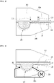
- Fig. 2 is a diagram showing a slot die coating apparatus according to an embodiment of the present disclosure.
- the slot die coating apparatus 200 includes a first die block 200a and a second die block 200b.
- the first die block 200a and the second die block 200b can be connected by a coupling part 201, and the coupling part 201 can be rotated by a hinge so that the first die block 200a and the second die block 200b come into contact with each other.
- a plate material 230 (shim) may be disposed on the first die block 200a and the second die block 200b, and the plate material may be a thin metal plate.
- the slot die coating apparatus 200 includes a sensor unit for measuring the flow rate of the electrode active material slurry which is discharged via the discharge port 120 formed by the coupling of the first die block 200a and the second die block 200b, and a control unit for adjusting the flow rate of the electrode active material slurry in response to the signal detected by the sensor unit.
- the sensor unit may be a non-contact flow meter, and as an example, it may be an energy detection sensor 210.
- a slurry supply part 310 and a slurry recovery part 320 may be formed in the manifold 220 formed in the second die block 200b.
- the control unit may be a flow rate control pump described later, and the flow rate control pump may be located between the slurry recovery part 320 and the slurry supply part 310.
- the manifold 220 is a space in which the slurry is stored in the slot die coating apparatus 200, which is an internal space of the mechanism for allowing the slurry to come out at a uniform flow rate.
- a slurry inlet 260 connected to the slurry feeding port 250 of Fig. 1 may be formed in the manifold 220.
- Fig. 3 is a diagram showing the structure of a non-contact flow meter included in the slot die coating apparatus of Fig. 2 .
- the non-contact flow meter is a sensor unit that measures the flow rate of the electrode active material slurry discharged through the discharge port 120.
- the non-contact flow meter may be an energy detection sensor 210.
- the energy detection sensor 210 may be formed inside the first die block 200a and may be connected to the discharge port 120 through the energy dissipation part 212 and the energy absorption part 214.
- the energy dissipation part 212 and the energy absorption part 214 may be located apart from each other along the discharge direction of the discharge port 120.
- the sensor unit should be able to check the flowing amount of slurry.
- the energy dissipation part 212 and the energy absorption part 214 may be formed of a transparent material so that the slurry does not come into contact with the sensor unit.
- the transparent material may be an engineering plastic or glass material having excellent wear resistance.
- the energy detection sensor 210 can detect infrared energy or magnetic force energy of the electrode active material slurry 105 and thus, measure the flow rate of the electrode active material slurry 105. Specifically, the energy generated by the energy detection sensor 210 is irradiated to the electrode active material slurry 105 through the energy dissipation part 212, and the energy signal of the irradiated electrode active material slurry 105 is received from the energy detection sensor 210 through the energy absorption part 214, whereby a flow rate that can be discharged to the discharge port 120 can be measured.
- the energy dissipation part 212 applies a certain amount of heat to the slurry, and when the heated slurry passes through the energy absorption part 214, it can recognize a signal and measure the flow rate.
- the energy dissipation part 212 corresponds to the signal generating part of the energy detection sensor 210, and the energy absorption part 214 may correspond to the signal receiving part of the energy detection sensor 210.
- Fig. 4 is a diagram showing the structure of a flow rate control pump included in the slot die coating apparatus of Fig. 2 .
- a slurry supply part 310 and a slurry recovery part 320 are formed in the manifold 220 formed in the second die block 200b.
- the slurry supply part 310 and the slurry recovery part 320 can circulate the electrode active material slurry 105 in the manifold 220.
- the flow rate control pump 300 is formed between the slurry supply part 310 and the slurry recovery part 320.
- the slurry recovery part 320 and the slurry supply part 310 are in fluid communication with the flow rate control pump 300, and the electrode active material slurry 105 recovered in the slurry recovery part 320 can pass through the flow rate control pump 300 and supplied to the manifold 220 via the slurry supply part 310.
- the slurry recovery part 320 is located ahead of the discharge port 120 along the discharge direction D2 of the electrode active material slurry 105 to recover the electrode active material slurry 105 and thus reduce the supply flow rate of the slurry.
- the slurry supply part 310 can re-supply the recovered electrode active material slurry 105 to the manifold 220 to increase the supply flow rate of the slurry.
- Fig. 5 is a diagram showing a first die block included in the slot die coating apparatus of Fig. 2 .
- Fig. 6 is a diagram showing a first die block included in the slot die coating apparatus of Fig. 2 .
- Fig. 7 is a diagram showing a first die block included in the slot die coating apparatus of Fig. 2 .
- the energy dissipation part 212 and the energy absorption part 214 are formed in a plural number along a direction perpendicular to the discharge direction D2 of the discharge port, respectively, and the plurality of the formed energy dissipation parts 212 may be located apart from each other, and the plurality of the energy absorption parts 214 may be located apart from each other.
- the plurality of the energy dissipation parts 212 and the energy absorption parts 214 are disposed at regular intervals in the width direction of the first die block 200a, and the energy detection sensor 210 can be formed so as to correspond to the group including the energy dissipation part 212 and the energy absorption part 214, thereby capable of measuring the flow rate of the electrode active material slurry for each position.
- Fig. 8 is a diagram showing a second die block included in the slot die coating apparatus of Fig. 2 .
- Fig. 9 is a diagram showing a second die block included in the slot die coating apparatus of Fig. 2 .
- Fig. 10 is a diagram showing a second die block included in the slot die coating apparatus of Fig. 2 .
- the slurry supply part 310 and the slurry recovery part 320 are each formed in a plural number along a direction perpendicular to the discharge direction D2 of the discharge port, and the plurality of formed slurry supply parts 310 may be located apart from each other, and the plurality of formed slurry recovery parts 320 may be located apart from each other.
- the plurality of the slurry supply parts 310 and the slurry recovery part 320 are disposed at regular intervals in the width direction of the second die block 200b, and the flow rate control pump 300 can be formed so as to correspond to the group including the slurry supply part 310 and the slurry recovery part 320, thereby capable of measuring the flow rate of the electrode active material slurry for each position.
- the flow rate control pump 300 may control the pressure by circulating the electrode active material slurry in the manifold 220 .
Landscapes
- Engineering & Computer Science (AREA)
- Chemical & Material Sciences (AREA)
- Manufacturing & Machinery (AREA)
- Chemical Kinetics & Catalysis (AREA)
- Electrochemistry (AREA)
- General Chemical & Material Sciences (AREA)
- Physics & Mathematics (AREA)
- Fluid Mechanics (AREA)
- Materials Engineering (AREA)
- Battery Electrode And Active Subsutance (AREA)
- Coating Apparatus (AREA)
Abstract
Description
- This application claims the benefit of
Korean Patent Application No. 10-2020-0034016 filed on March 19, 2020 Korean Patent Application No. 10-2021-0034347 filed on March 17, 2021 - The present disclosure relates to a slot die coating apparatus, and more particularly, to a slot die coating apparatus for improving coating uniformity.
- With the increase of the technological development and demand for a mobile device, demand for a secondary battery as an energy source is rapidly increasing, and accordingly, many researches of the battery capable of meeting a variety of needs are emerging.
- A secondary battery has attracted considerable attention as an energy source for powerdriven devices, such as an electric bicycle, an electric vehicle, and a hybrid electric vehicle, as well as an energy source for mobile devices, such as a mobile phone, a digital camera, and a laptop computer.
- Meanwhile, the process of producing a secondary battery may include a step in which a positive electrode conductive current collector and a negative electrode conductive current collector are each coated with an active material, a binder, a conductive material and the like to a predetermined thickness in the form of a slurry, and then dried. Then, an electrode assembly formed by winding or stacking the two current collectors with a separator interposed therebetween is accommodated in a cylindrical or prismatic can, pouch, or the like, and sealed to produce a secondary battery.
- In order to uniformize the charging/discharging characteristics of the secondary battery, the slurry containing such an active material should be uniformly coated onto the current collector. For this purpose, a slot die coating process can be performed. The slot die coating is a method in which a slurry is supplied between thin metal plates in the shape of a nozzle called a slot die using a pump, and coated onto the surface of the current collector to a certain thickness. At this time, in order to achieve a uniform coating, it is important to control the viscosity of the slurry, the flow of slurry, and the distance between the slot die and the current collector.
- However, as an electrode whose width gradually becomes wide is coated, the flow rate of the slurry exiting the slot die may cause large deviation depending on the shape of the slot die and its position in the slot die. In addition, it is difficult to measure the flow rate flowing out through the slot die, and once the shape and thickness of the thin metal plate of the slot die are determined, the shape and thickness of the slot die cannot be changed in real time during coating, which causes a problem that the flow rate of the slurry cannot be controlled. Accordingly, an imbalance in the electrode coating will occur.
- It is an object of the present disclosure to provide a slot die coating apparatus for improving coating uniformity.
- However, the problem to be solved by the embodiments of the present disclosure is not limited to the above-described problems, and can be variously expanded within the scope of the technical idea included in the present disclosure.
- According to one embodiment of the present disclosure, there is provided a slot die coating apparatus comprising: a slot die containing a first die block and a second die block, and a sensor unit for measuring the flow rate of an electrode active material slurry which is discharged through a discharge port formed by the coupling of the first die block and the second die block, wherein the sensor unit is formed inside the first die block, and the sensor unit is connected to the discharge port via an energy dissipation part and an energy absorption part.
- The energy dissipation part and the energy absorption part may be formed of a transparent material.
- The sensor unit may detect infrared energy or magnetic force energy of the electrode active material slurry and measure the flow rate of the electrode active material slurry.
- The energy dissipation part and the energy absorption part may be located apart from each other along the discharge direction of the discharge port.
- The energy dissipation part and the energy absorption part may be respectively formed in a plural number along a direction perpendicular to the discharge direction of the discharge port, the plurality of the energy dissipation parts formed may be located apart from each other, and the plurality of the energy absorption parts may be located apart from each other.
- A manifold may be formed on the second die block, and a slurry supply part and a slurry recovery part may be formed in the manifold.
- The slot die coating apparatus may further include a control unit for adjusting the flow rate of the electrode active material slurry in response to a signal detected by the sensor unit.
- The control unit may include a flow rate control pump located between the slurry recovery part and the slurry supply part.
- The slurry recovery part and the slurry supply part are in fluid communication with the flow rate control pump, and the electrode active material slurry recovered by the slurry recovery part may pass through the flow rate control pump and may be supplied to the manifold via the slurry supply part.
- The slurry recovery part is located ahead of the discharge port along the discharge direction of the electrode active material slurry to recover the electrode active material slurry and reduce the supply flow rate of the slurry, and the slurry supply part re-supplies the recovered electrode active material slurry to the manifold to increase the supply flow rate of the slurry.
- According to embodiments of the present disclosure, a precision flow meter is installed at the outlet of the slot die from which the slurry exits, thereby capable of measuring the slurry flow rate for each position.
- In order to uniformly adjust the detected slurry flow rate for each position in real time, a pump is installed, whereby a slurry is circulated in a manifold, which is a space in which the slurry is stored inside the slot die, thereby capable of adjusting the pressure.
-
-
Fig. 1 is a diagram schematically showing a process of slurry coating using a slot die coating apparatus according to an embodiment of the present disclosure; -
Fig. 2 is a diagram showing a slot die coating apparatus according to an embodiment of the present disclosure; -
Fig. 3 is a diagram showing the structure of a non-contact flow meter included in the slot die coating apparatus ofFig. 2 ; -
Fig. 4 is a diagram showing the structure of a flow rate control pump included in the slot die coating apparatus ofFig. 2 ; -
Fig. 5 is a diagram showing a first die block included in the slot die coating apparatus ofFig. 2 ; -
Fig. 6 is a diagram showing a first die block included in the slot die coating apparatus ofFig. 2 ; -
Fig. 7 is a diagram showing a first die block included in the slot die coating apparatus ofFig. 2 ; -
Fig. 8 is a diagram showing a second die block included in the slot die coating apparatus ofFig. 2 ; -
Fig. 9 is a diagram showing a second die block included in the slot die coating apparatus ofFig. 2 ; and -
Fig. 10 is a diagram showing a second die block included in the slot die coating apparatus ofFig. 2 . - Hereinafter, various embodiments of the present disclosure will be described in detail with reference to the accompanying drawings so that those skilled in the art can easily implement them. The present disclosure can be modified in various different ways, and is not limited to the embodiments set forth herein.
- Portions that are irrelevant to the description will be omitted to clearly describe the present disclosure, and like reference numerals designate like elements throughout the specification.
- Further, in the drawings, the size and thickness of each element are arbitrarily illustrated for convenience of description, and the present disclosure is not necessarily limited to those illustrated in the drawings. In the drawings, the thickness of layers, regions, etc. are exaggerated for clarity. In the drawings, for convenience of description, the thicknesses of some layers and regions are shown to be exaggerated.
- Further, it will be understood that when an element such as a layer, film, region, or plate is referred to as being "on" or "above" another element, it can be directly on the other element or intervening elements may also be present. In contrast, when an element is referred to as being "directly on" another element, it means that other intervening elements are not present. Further, the word "on" or "above" means disposed on or below a reference portion, and does not necessarily mean being disposed on the upper end of the reference portion toward the opposite direction of gravity.
- Further, throughout the specification, when a portion is referred to as "including" a certain component, it means that the portion can further include other components, without excluding the other components, unless otherwise stated.
- Further, throughout the specification, when referred to as "planar", it means when a target portion is viewed from the upper side, and when referred to as "cross-sectional", it means when a target portion is viewed from the side of a cross section cut vertically.
-
Fig. 1 is a diagram schematically showing a process of slurry coating using a slot die coating apparatus according to an embodiment of the present disclosure. - Referring to
Fig. 1 , the slotdie coating apparatus 200 according to the embodiment of the present disclosure can coat the electrodeactive material slurry 105 onto the electrodecurrent collector 110 while moving in one direction D1. The electrodeactive material slurry 105 is a mixture prepared in a low fluidity state by mixing fine solid particles in a liquid, and an electrode slurry prepared by mixing a binder with a solvent in a certain ratio can be coated as a thin film onto theelectrode current collector 110 and then subjected to drying and pressing process to produce an electrode for a secondary battery. The electrode slurry includes an active material, a binder, a conductive material, and the like, and the active material may be a positive electrode active material or a negative electrode active material. - The
discharge port 120 of the slotdie coating apparatus 200 may be disposed toward theelectrode current collector 110 in a direction perpendicular to the upper surface of theelectrode current collector 110. The slurry injected into the slotdie coating apparatus 200 via aslurry feeding port 250 can be discharged via thedischarge port 120. Generally, in order to control the flow rate of the slurry coming out of thedischarge port 120 of the slotdie coating apparatus 200, it is possible to change the design of the internal structure of the manifold of the slotdie coating apparatus 200, or adjust a distance between the die block of the slotdie coating apparatus 200 and theelectrode current collector 110. According to the embodiment of the present disclosure, the flow rate can be controlled more precisely by the improved slot die coating apparatus in order to minimize the flow rate deviation, without simply changing the design of the internal structure of the manifold or adjusting the slurry discharge interval, or the like. Specifically, according to the existing flow control method, when a slight difference occurred in the flow rate of the slurry in the full width direction at the discharge die, it can be seen only by checking the coated electrode, whereas according to the embodiment of the present disclosure, a flow meter can be installed for each section in the full width direction, thereby detecting the difference in flow rate and adjusting the flow rate uniformly. - More detailed descriptions will be given below.
-
Fig. 2 is a diagram showing a slot die coating apparatus according to an embodiment of the present disclosure. - Referring to
Fig. 2 , the slot diecoating apparatus 200 according to the embodiment of the present disclosure includes afirst die block 200a and asecond die block 200b. Thefirst die block 200a and thesecond die block 200b can be connected by acoupling part 201, and thecoupling part 201 can be rotated by a hinge so that thefirst die block 200a and thesecond die block 200b come into contact with each other. A plate material 230 (shim) may be disposed on thefirst die block 200a and thesecond die block 200b, and the plate material may be a thin metal plate. - The slot die
coating apparatus 200 according to the embodiment of the present disclosure includes a sensor unit for measuring the flow rate of the electrode active material slurry which is discharged via thedischarge port 120 formed by the coupling of thefirst die block 200a and thesecond die block 200b, and a control unit for adjusting the flow rate of the electrode active material slurry in response to the signal detected by the sensor unit. The sensor unit may be a non-contact flow meter, and as an example, it may be anenergy detection sensor 210. Aslurry supply part 310 and aslurry recovery part 320 may be formed in the manifold 220 formed in thesecond die block 200b. The control unit may be a flow rate control pump described later, and the flow rate control pump may be located between theslurry recovery part 320 and theslurry supply part 310. - The manifold 220 is a space in which the slurry is stored in the slot die
coating apparatus 200, which is an internal space of the mechanism for allowing the slurry to come out at a uniform flow rate. Aslurry inlet 260 connected to theslurry feeding port 250 ofFig. 1 may be formed in themanifold 220. -
Fig. 3 is a diagram showing the structure of a non-contact flow meter included in the slot die coating apparatus ofFig. 2 . - Referring to
Fig. 3 , the non-contact flow meter according to the embodiment of the present disclosure is a sensor unit that measures the flow rate of the electrode active material slurry discharged through thedischarge port 120. The non-contact flow meter may be anenergy detection sensor 210. Theenergy detection sensor 210 may be formed inside thefirst die block 200a and may be connected to thedischarge port 120 through theenergy dissipation part 212 and theenergy absorption part 214. Theenergy dissipation part 212 and theenergy absorption part 214 may be located apart from each other along the discharge direction of thedischarge port 120. The sensor unit should be able to check the flowing amount of slurry. However, if the sensor unit is configured in a contact type, the sensor unit obstructs the flowing of the slurry and thus, the flow rate of the slurry cannot be accurately measured. Therefore, theenergy dissipation part 212 and theenergy absorption part 214 according to the embodiment of the present disclosure may be formed of a transparent material so that the slurry does not come into contact with the sensor unit. The transparent material may be an engineering plastic or glass material having excellent wear resistance. - The
energy detection sensor 210 according to the embodiment of the present disclosure can detect infrared energy or magnetic force energy of the electrodeactive material slurry 105 and thus, measure the flow rate of the electrodeactive material slurry 105. Specifically, the energy generated by theenergy detection sensor 210 is irradiated to the electrodeactive material slurry 105 through theenergy dissipation part 212, and the energy signal of the irradiated electrodeactive material slurry 105 is received from theenergy detection sensor 210 through theenergy absorption part 214, whereby a flow rate that can be discharged to thedischarge port 120 can be measured. For example, theenergy dissipation part 212 applies a certain amount of heat to the slurry, and when the heated slurry passes through theenergy absorption part 214, it can recognize a signal and measure the flow rate. Theenergy dissipation part 212 corresponds to the signal generating part of theenergy detection sensor 210, and theenergy absorption part 214 may correspond to the signal receiving part of theenergy detection sensor 210. -
Fig. 4 is a diagram showing the structure of a flow rate control pump included in the slot die coating apparatus ofFig. 2 . - Referring to
Fig. 4 , aslurry supply part 310 and aslurry recovery part 320 are formed in the manifold 220 formed in thesecond die block 200b. Theslurry supply part 310 and theslurry recovery part 320 can circulate the electrodeactive material slurry 105 in themanifold 220. According to the embodiment of the present disclosure, the flowrate control pump 300 is formed between theslurry supply part 310 and theslurry recovery part 320. Theslurry recovery part 320 and theslurry supply part 310 are in fluid communication with the flowrate control pump 300, and the electrodeactive material slurry 105 recovered in theslurry recovery part 320 can pass through the flowrate control pump 300 and supplied to the manifold 220 via theslurry supply part 310. - Specifically, the
slurry recovery part 320 is located ahead of thedischarge port 120 along the discharge direction D2 of the electrodeactive material slurry 105 to recover the electrodeactive material slurry 105 and thus reduce the supply flow rate of the slurry. Theslurry supply part 310 can re-supply the recovered electrodeactive material slurry 105 to the manifold 220 to increase the supply flow rate of the slurry. -
Fig. 5 is a diagram showing a first die block included in the slot die coating apparatus ofFig. 2 .Fig. 6 is a diagram showing a first die block included in the slot die coating apparatus ofFig. 2 .Fig. 7 is a diagram showing a first die block included in the slot die coating apparatus ofFig. 2 . - Referring to
Figs. 5 to 7 , theenergy dissipation part 212 and theenergy absorption part 214 are formed in a plural number along a direction perpendicular to the discharge direction D2 of the discharge port, respectively, and the plurality of the formedenergy dissipation parts 212 may be located apart from each other, and the plurality of theenergy absorption parts 214 may be located apart from each other. As described above, the plurality of theenergy dissipation parts 212 and theenergy absorption parts 214 are disposed at regular intervals in the width direction of thefirst die block 200a, and theenergy detection sensor 210 can be formed so as to correspond to the group including theenergy dissipation part 212 and theenergy absorption part 214, thereby capable of measuring the flow rate of the electrode active material slurry for each position. -
Fig. 8 is a diagram showing a second die block included in the slot die coating apparatus ofFig. 2 .Fig. 9 is a diagram showing a second die block included in the slot die coating apparatus ofFig. 2 .Fig. 10 is a diagram showing a second die block included in the slot die coating apparatus ofFig. 2 . - Referring to
Figs. 8 to 10 , theslurry supply part 310 and theslurry recovery part 320 are each formed in a plural number along a direction perpendicular to the discharge direction D2 of the discharge port, and the plurality of formedslurry supply parts 310 may be located apart from each other, and the plurality of formedslurry recovery parts 320 may be located apart from each other. In this way, the plurality of theslurry supply parts 310 and theslurry recovery part 320 are disposed at regular intervals in the width direction of thesecond die block 200b, and the flowrate control pump 300 can be formed so as to correspond to the group including theslurry supply part 310 and theslurry recovery part 320, thereby capable of measuring the flow rate of the electrode active material slurry for each position. The flowrate control pump 300 may control the pressure by circulating the electrode active material slurry in themanifold 220 . - Although preferred embodiments of the present disclosure have been described in detail above, the scope of the present disclosure is not limited thereto, and various modifications and improvements made by those skilled in the art using the basic concepts of the present disclosure, which are defined in the appended claims, also belong to the scope of the present disclosure.
-
- 105:
- electrode active material slurry
- 110:
- electrode current collector
- 120:
- discharge port
- 200:
- slot die coating apparatus
- 200a:
- first die block
- 200b:
- second die block
- 210:
- energy detection sensor
- 212:
- energy dissipation part
- 214:
- energy absorption part
- 220:
- manifold
- 300:
- flow rate control pump
- 310:
- slurry supply part
- 320:
- slurry recovery part
Claims (10)
- A slot die coating apparatus comprising:a slot die containing a first die block and a second die block, anda sensor unit for measuring the flow rate of an electrode active material slurry which is discharged through a discharge port formed by the coupling of the first die block and the second die block,wherein the sensor unit is formed inside the first die block, and the sensor unit is connected to the discharge port via an energy dissipation part and an energy absorption part.
- The slot die coating apparatus of claim 1, wherein
the energy dissipation part and the energy absorption part are formed of a transparent material. - The slot die coating apparatus of claim 2, wherein
the sensor unit detects infrared energy or magnetic force energy of the electrode active material slurry and measures the flow rate of the electrode active material slurry. - The slot die coating apparatus of claim 2, wherein
the energy dissipation part and the energy absorption part are located apart from each other along a discharge direction of the discharge port. - The slot die coating apparatus of claim 4, wherein
the energy dissipation part and the energy absorption part are respectively formed in a plural number along a direction perpendicular to the discharge direction of the discharge port, the plurality of the energy dissipation parts formed are located apart from each other, and the plurality of the energy absorption parts are located apart from each other. - The slot die coating apparatus of claim 1, wherein
a manifold is formed on the second die block, and a slurry supply part and a slurry recovery part are formed in the manifold. - The slot die coating apparatus of claim 1,
which further comprises a control unit for adjusting the flow rate of the electrode active material slurry in response to a signal detected by the sensor unit. - The slot die coating apparatus of claim 7, wherein
the control unit comprises a flow rate control pump located between the slurry recovery part and the slurry supply part. - The slot die coating apparatus of claim 8, wherein
the slurry recovery part and the slurry supply part are in fluid communication with the flow rate control pump, and the electrode active material slurry recovered by the slurry recovery part passes through the flow rate control pump and is supplied to the manifold via the slurry supply part. - The slot die coating apparatus of claim 9, wherein
the slurry recovery part is located ahead of the discharge port along the discharge direction of the electrode active material slurry to recover the electrode active material slurry and reduce the supply flow rate of the slurry, and the slurry supply part re-supplies the recovered electrode active material slurry to the manifold to increase the supply flow rate of the slurry.
Applications Claiming Priority (3)
| Application Number | Priority Date | Filing Date | Title |
|---|---|---|---|
| KR20200034016 | 2020-03-19 | ||
| KR1020210034347A KR102655289B1 (en) | 2020-03-19 | 2021-03-17 | Slot die coating apparatus |
| PCT/KR2021/003343 WO2021187908A1 (en) | 2020-03-19 | 2021-03-18 | Slot die coating device |
Publications (3)
| Publication Number | Publication Date |
|---|---|
| EP3984653A1 true EP3984653A1 (en) | 2022-04-20 |
| EP3984653A4 EP3984653A4 (en) | 2022-11-02 |
| EP3984653B1 EP3984653B1 (en) | 2025-02-12 |
Family
ID=77771531
Family Applications (1)
| Application Number | Title | Priority Date | Filing Date |
|---|---|---|---|
| EP21770473.3A Active EP3984653B1 (en) | 2020-03-19 | 2021-03-18 | Slot die coating apparatus |
Country Status (6)
| Country | Link |
|---|---|
| US (1) | US12202005B2 (en) |
| EP (1) | EP3984653B1 (en) |
| CN (1) | CN114007763B (en) |
| ES (1) | ES3013887T3 (en) |
| HU (1) | HUE070370T2 (en) |
| WO (1) | WO2021187908A1 (en) |
Families Citing this family (2)
| Publication number | Priority date | Publication date | Assignee | Title |
|---|---|---|---|---|
| CN218167601U (en) * | 2022-10-08 | 2022-12-30 | 宁德时代新能源科技股份有限公司 | Coating die head and coating equipment with same |
| KR20240088000A (en) * | 2022-12-13 | 2024-06-20 | 주식회사 엘지에너지솔루션 | Apparatus for manufacruring negative electrode sheet of secondary battery |
Family Cites Families (34)
| Publication number | Priority date | Publication date | Assignee | Title |
|---|---|---|---|---|
| CA992348A (en) * | 1974-03-22 | 1976-07-06 | Helen G. Tucker | Measurement of at least one of the fluid flow rate and viscous characteristics using laminar flow and viscous shear |
| US4170133A (en) * | 1978-05-08 | 1979-10-09 | Gardner William L | Planar helical flowmeter |
| JP2520720B2 (en) * | 1989-03-16 | 1996-07-31 | 富士写真フイルム株式会社 | Application method |
| JPH06226181A (en) | 1993-01-30 | 1994-08-16 | Sumitomo Metal Ind Ltd | Slot nozzle coater type coating device |
| JP3717996B2 (en) | 1996-05-17 | 2005-11-16 | 株式会社コガネイ | Chemical supply device |
| JP2917127B2 (en) * | 1996-07-12 | 1999-07-12 | 井上金属工業株式会社 | Coating device |
| JP2001018212A (en) * | 1999-07-05 | 2001-01-23 | Murata Mfg Co Ltd | Extrusion mold |
| US6818062B2 (en) * | 2001-10-29 | 2004-11-16 | Fuji Photo Film Co., Ltd. | Coating method and apparatus |
| US7143637B1 (en) * | 2003-04-11 | 2006-12-05 | Mcbrearty Michael | Dielectric slit die for in-line monitoring of liquids processing |
| JP4315786B2 (en) * | 2003-11-18 | 2009-08-19 | 大日本スクリーン製造株式会社 | Substrate processing apparatus and method of filling processing liquid into slit nozzle |
| JP4590860B2 (en) | 2003-11-27 | 2010-12-01 | 凸版印刷株式会社 | Coating apparatus and coating method using the same |
| US20050181245A1 (en) * | 2005-03-28 | 2005-08-18 | Honeywell International Inc. | Hydrogen and electrical power generator |
| TWI244941B (en) * | 2005-02-01 | 2005-12-11 | Univ Tsinghua | Apparatus and process for block coating |
| US20070251450A1 (en) * | 2006-04-28 | 2007-11-01 | Applied Materials, Inc. | Systems and Methods for Monitoring and Controlling Dispense Using a Digital Optical Sensor |
| JP5368833B2 (en) | 2009-03-05 | 2013-12-18 | トヨタ自動車株式会社 | Coating machine |
| JP2012061444A (en) | 2010-09-17 | 2012-03-29 | Nec Corp | Coating apparatus |
| KR20120047426A (en) | 2010-11-04 | 2012-05-14 | 김철수 | Die coaters for forming a coating layer having uniform thickness |
| EP2668473A1 (en) * | 2011-01-24 | 2013-12-04 | M.T.R. Wireless Communications Ltd. | Flow meter apparatus |
| JP2013140680A (en) | 2011-12-28 | 2013-07-18 | Nissan Motor Co Ltd | Production method for electrode and production control system of electrode |
| JP2013215644A (en) | 2012-04-05 | 2013-10-24 | Fujifilm Corp | Coating method and coating apparatus |
| GB201211557D0 (en) | 2012-06-29 | 2012-08-15 | Ibm | Microfluidic surface processing device and method |
| JP2014147857A (en) | 2013-01-31 | 2014-08-21 | Hitachi Vehicle Energy Ltd | Die coater |
| JP6084480B2 (en) | 2013-02-19 | 2017-02-22 | 東レエンジニアリング株式会社 | Battery electrode plate manufacturing apparatus and method |
| JP6422711B2 (en) | 2013-10-11 | 2018-11-14 | 東レエンジニアリング株式会社 | Battery electrode plate manufacturing apparatus and method |
| JP6074356B2 (en) | 2013-12-18 | 2017-02-01 | 日東電工株式会社 | Coating apparatus and coating film manufacturing method |
| JP6280383B2 (en) | 2014-02-12 | 2018-02-14 | 東レエンジニアリング株式会社 | Battery plate manufacturing equipment |
| JP6215098B2 (en) | 2014-03-17 | 2017-10-18 | 東レエンジニアリング株式会社 | Battery plate manufacturing equipment |
| JP6397683B2 (en) | 2014-07-31 | 2018-09-26 | 東レエンジニアリング株式会社 | Battery plate manufacturing equipment |
| JP6391366B2 (en) | 2014-08-26 | 2018-09-19 | 東レエンジニアリング株式会社 | Battery plate manufacturing equipment |
| JP2016059907A (en) | 2014-09-22 | 2016-04-25 | 株式会社豊田自動織機 | Coating apparatus |
| KR102058062B1 (en) | 2015-09-18 | 2019-12-20 | 주식회사 엘지화학 | Electrode coating apparatus and manufacturing method for secondary battery |
| JP6425776B1 (en) | 2017-08-10 | 2018-11-21 | 東レエンジニアリング株式会社 | Coating apparatus and coating method |
| KR102386531B1 (en) | 2017-09-14 | 2022-04-15 | 엘지전자 주식회사 | Slurry Coating Apparatus |
| JP6940434B2 (en) * | 2018-03-13 | 2021-09-29 | アズビル株式会社 | Capacitive electromagnetic flowmeter |
-
2021
- 2021-03-18 EP EP21770473.3A patent/EP3984653B1/en active Active
- 2021-03-18 US US17/626,718 patent/US12202005B2/en active Active
- 2021-03-18 HU HUE21770473A patent/HUE070370T2/en unknown
- 2021-03-18 CN CN202180003993.6A patent/CN114007763B/en active Active
- 2021-03-18 WO PCT/KR2021/003343 patent/WO2021187908A1/en not_active Ceased
- 2021-03-18 ES ES21770473T patent/ES3013887T3/en active Active
Also Published As
| Publication number | Publication date |
|---|---|
| ES3013887T3 (en) | 2025-04-15 |
| CN114007763B (en) | 2024-02-20 |
| US12202005B2 (en) | 2025-01-21 |
| WO2021187908A1 (en) | 2021-09-23 |
| EP3984653B1 (en) | 2025-02-12 |
| EP3984653A4 (en) | 2022-11-02 |
| US20220241813A1 (en) | 2022-08-04 |
| CN114007763A (en) | 2022-02-01 |
| HUE070370T2 (en) | 2025-06-28 |
Similar Documents
| Publication | Publication Date | Title |
|---|---|---|
| EP3984653B1 (en) | Slot die coating apparatus | |
| Diehm et al. | In situ investigations of simultaneous two‐layer slot die coating of component‐graded anodes for improved high‐energy Li‐ion batteries | |
| US8267039B2 (en) | Coating apparatus and method of applying coating liquid | |
| US12515235B2 (en) | Dual-slot die coater | |
| KR101469332B1 (en) | Production method of electrode and production control system of electrode | |
| JP6422711B2 (en) | Battery electrode plate manufacturing apparatus and method | |
| CN115175770B (en) | Slot die coater with improved coating solution flow | |
| Diehm et al. | Edge Formation in High‐Speed Intermittent Slot‐Die Coating of Disruptively Stacked Thick Battery Electrodes | |
| US20230131033A1 (en) | Method of Managing Sliding Region of Electrode | |
| JP7788629B2 (en) | Intermittent valve and intermittent coating device | |
| EP4134168A1 (en) | Multiple slot die coater | |
| US20230166287A1 (en) | Multi-Slot Die Coater | |
| EP4106035B1 (en) | Electrode assembly comprising anode and anode sheet having improved electrode stacking properties and manufacturing method therefor | |
| JP2012216375A (en) | Coating device and coating film formation system | |
| US12157140B2 (en) | Multi-slot die coater | |
| KR102655289B1 (en) | Slot die coating apparatus | |
| JP6184819B2 (en) | Nozzle adjustment method and double-side coating apparatus | |
| KR20190007746A (en) | Coating Apparatus | |
| JP6011007B2 (en) | Coating system | |
| EP3900844A1 (en) | Electrode slurry coating method and apparatus comprising pressure adjustment member | |
| CN104755181A (en) | Coating head with inner deckle | |
| EP4579772A1 (en) | Apparatus and method for measuring electrode plate thickness | |
| KR102839789B1 (en) | Slot die comprising a member that prevents the occurrence of drag lines and device for manufacturing electrode comprising the same | |
| EP4732962A1 (en) | Slot die coater | |
| KR102666187B1 (en) | Dual slot die coater |
Legal Events
| Date | Code | Title | Description |
|---|---|---|---|
| STAA | Information on the status of an ep patent application or granted ep patent |
Free format text: STATUS: THE INTERNATIONAL PUBLICATION HAS BEEN MADE |
|
| PUAI | Public reference made under article 153(3) epc to a published international application that has entered the european phase |
Free format text: ORIGINAL CODE: 0009012 |
|
| STAA | Information on the status of an ep patent application or granted ep patent |
Free format text: STATUS: REQUEST FOR EXAMINATION WAS MADE |
|
| 17P | Request for examination filed |
Effective date: 20220113 |
|
| AK | Designated contracting states |
Kind code of ref document: A1 Designated state(s): AL AT BE BG CH CY CZ DE DK EE ES FI FR GB GR HR HU IE IS IT LI LT LU LV MC MK MT NL NO PL PT RO RS SE SI SK SM TR |
|
| A4 | Supplementary search report drawn up and despatched |
Effective date: 20221005 |
|
| RIC1 | Information provided on ipc code assigned before grant |
Ipc: H01M 4/04 20060101ALI20220928BHEP Ipc: B05C 11/10 20060101ALI20220928BHEP Ipc: B05C 5/02 20060101AFI20220928BHEP |
|
| STAA | Information on the status of an ep patent application or granted ep patent |
Free format text: STATUS: EXAMINATION IS IN PROGRESS |
|
| 17Q | First examination report despatched |
Effective date: 20230315 |
|
| DAV | Request for validation of the european patent (deleted) | ||
| DAX | Request for extension of the european patent (deleted) | ||
| GRAP | Despatch of communication of intention to grant a patent |
Free format text: ORIGINAL CODE: EPIDOSNIGR1 |
|
| STAA | Information on the status of an ep patent application or granted ep patent |
Free format text: STATUS: GRANT OF PATENT IS INTENDED |
|
| INTG | Intention to grant announced |
Effective date: 20240919 |
|
| P01 | Opt-out of the competence of the unified patent court (upc) registered |
Free format text: CASE NUMBER: APP_56680/2024 Effective date: 20241017 |
|
| GRAS | Grant fee paid |
Free format text: ORIGINAL CODE: EPIDOSNIGR3 |
|
| GRAA | (expected) grant |
Free format text: ORIGINAL CODE: 0009210 |
|
| STAA | Information on the status of an ep patent application or granted ep patent |
Free format text: STATUS: THE PATENT HAS BEEN GRANTED |
|
| AK | Designated contracting states |
Kind code of ref document: B1 Designated state(s): AL AT BE BG CH CY CZ DE DK EE ES FI FR GB GR HR HU IE IS IT LI LT LU LV MC MK MT NL NO PL PT RO RS SE SI SK SM TR |
|
| REG | Reference to a national code |
Ref country code: GB Ref legal event code: FG4D |
|
| REG | Reference to a national code |
Ref country code: CH Ref legal event code: EP |
|
| REG | Reference to a national code |
Ref country code: DE Ref legal event code: R096 Ref document number: 602021026054 Country of ref document: DE |
|
| REG | Reference to a national code |
Ref country code: IE Ref legal event code: FG4D |
|
| REG | Reference to a national code |
Ref country code: ES Ref legal event code: FG2A Ref document number: 3013887 Country of ref document: ES Kind code of ref document: T3 Effective date: 20250415 |
|
| PGFP | Annual fee paid to national office [announced via postgrant information from national office to epo] |
Ref country code: AT Payment date: 20250417 Year of fee payment: 5 |
|
| REG | Reference to a national code |
Ref country code: NL Ref legal event code: MP Effective date: 20250212 |
|
| REG | Reference to a national code |
Ref country code: HU Ref legal event code: AG4A Ref document number: E070370 Country of ref document: HU |
|
| PG25 | Lapsed in a contracting state [announced via postgrant information from national office to epo] |
Ref country code: RS Free format text: LAPSE BECAUSE OF FAILURE TO SUBMIT A TRANSLATION OF THE DESCRIPTION OR TO PAY THE FEE WITHIN THE PRESCRIBED TIME-LIMIT Effective date: 20250512 |
|
| PG25 | Lapsed in a contracting state [announced via postgrant information from national office to epo] |
Ref country code: FI Free format text: LAPSE BECAUSE OF FAILURE TO SUBMIT A TRANSLATION OF THE DESCRIPTION OR TO PAY THE FEE WITHIN THE PRESCRIBED TIME-LIMIT Effective date: 20250212 |
|
| PG25 | Lapsed in a contracting state [announced via postgrant information from national office to epo] |
Ref country code: PL Free format text: LAPSE BECAUSE OF FAILURE TO SUBMIT A TRANSLATION OF THE DESCRIPTION OR TO PAY THE FEE WITHIN THE PRESCRIBED TIME-LIMIT Effective date: 20250212 |
|
| PGFP | Annual fee paid to national office [announced via postgrant information from national office to epo] |
Ref country code: ES Payment date: 20250408 Year of fee payment: 5 |
|
| REG | Reference to a national code |
Ref country code: LT Ref legal event code: MG9D |
|
| PG25 | Lapsed in a contracting state [announced via postgrant information from national office to epo] |
Ref country code: IS Free format text: LAPSE BECAUSE OF FAILURE TO SUBMIT A TRANSLATION OF THE DESCRIPTION OR TO PAY THE FEE WITHIN THE PRESCRIBED TIME-LIMIT Effective date: 20250612 Ref country code: NO Free format text: LAPSE BECAUSE OF FAILURE TO SUBMIT A TRANSLATION OF THE DESCRIPTION OR TO PAY THE FEE WITHIN THE PRESCRIBED TIME-LIMIT Effective date: 20250512 |
|
| PG25 | Lapsed in a contracting state [announced via postgrant information from national office to epo] |
Ref country code: NL Free format text: LAPSE BECAUSE OF FAILURE TO SUBMIT A TRANSLATION OF THE DESCRIPTION OR TO PAY THE FEE WITHIN THE PRESCRIBED TIME-LIMIT Effective date: 20250212 |
|
| PG25 | Lapsed in a contracting state [announced via postgrant information from national office to epo] |
Ref country code: HR Free format text: LAPSE BECAUSE OF FAILURE TO SUBMIT A TRANSLATION OF THE DESCRIPTION OR TO PAY THE FEE WITHIN THE PRESCRIBED TIME-LIMIT Effective date: 20250212 |
|
| PG25 | Lapsed in a contracting state [announced via postgrant information from national office to epo] |
Ref country code: LV Free format text: LAPSE BECAUSE OF FAILURE TO SUBMIT A TRANSLATION OF THE DESCRIPTION OR TO PAY THE FEE WITHIN THE PRESCRIBED TIME-LIMIT Effective date: 20250212 Ref country code: PT Free format text: LAPSE BECAUSE OF FAILURE TO SUBMIT A TRANSLATION OF THE DESCRIPTION OR TO PAY THE FEE WITHIN THE PRESCRIBED TIME-LIMIT Effective date: 20250612 |
|
| PG25 | Lapsed in a contracting state [announced via postgrant information from national office to epo] |
Ref country code: GR Free format text: LAPSE BECAUSE OF FAILURE TO SUBMIT A TRANSLATION OF THE DESCRIPTION OR TO PAY THE FEE WITHIN THE PRESCRIBED TIME-LIMIT Effective date: 20250513 Ref country code: BG Free format text: LAPSE BECAUSE OF FAILURE TO SUBMIT A TRANSLATION OF THE DESCRIPTION OR TO PAY THE FEE WITHIN THE PRESCRIBED TIME-LIMIT Effective date: 20250212 |
|
| REG | Reference to a national code |
Ref country code: AT Ref legal event code: MK05 Ref document number: 1765604 Country of ref document: AT Kind code of ref document: T Effective date: 20250212 |
|
| PG25 | Lapsed in a contracting state [announced via postgrant information from national office to epo] |
Ref country code: SE Free format text: LAPSE BECAUSE OF FAILURE TO SUBMIT A TRANSLATION OF THE DESCRIPTION OR TO PAY THE FEE WITHIN THE PRESCRIBED TIME-LIMIT Effective date: 20250212 |
|
| PG25 | Lapsed in a contracting state [announced via postgrant information from national office to epo] |
Ref country code: SM Free format text: LAPSE BECAUSE OF FAILURE TO SUBMIT A TRANSLATION OF THE DESCRIPTION OR TO PAY THE FEE WITHIN THE PRESCRIBED TIME-LIMIT Effective date: 20250212 |
|
| PG25 | Lapsed in a contracting state [announced via postgrant information from national office to epo] |
Ref country code: DK Free format text: LAPSE BECAUSE OF FAILURE TO SUBMIT A TRANSLATION OF THE DESCRIPTION OR TO PAY THE FEE WITHIN THE PRESCRIBED TIME-LIMIT Effective date: 20250212 |
|
| PG25 | Lapsed in a contracting state [announced via postgrant information from national office to epo] |
Ref country code: IT Free format text: LAPSE BECAUSE OF FAILURE TO SUBMIT A TRANSLATION OF THE DESCRIPTION OR TO PAY THE FEE WITHIN THE PRESCRIBED TIME-LIMIT Effective date: 20250212 |
|
| PG25 | Lapsed in a contracting state [announced via postgrant information from national office to epo] |
Ref country code: AT Free format text: LAPSE BECAUSE OF FAILURE TO SUBMIT A TRANSLATION OF THE DESCRIPTION OR TO PAY THE FEE WITHIN THE PRESCRIBED TIME-LIMIT Effective date: 20250212 |
|
| PG25 | Lapsed in a contracting state [announced via postgrant information from national office to epo] |
Ref country code: CZ Free format text: LAPSE BECAUSE OF FAILURE TO SUBMIT A TRANSLATION OF THE DESCRIPTION OR TO PAY THE FEE WITHIN THE PRESCRIBED TIME-LIMIT Effective date: 20250212 Ref country code: EE Free format text: LAPSE BECAUSE OF FAILURE TO SUBMIT A TRANSLATION OF THE DESCRIPTION OR TO PAY THE FEE WITHIN THE PRESCRIBED TIME-LIMIT Effective date: 20250212 |
|
| PG25 | Lapsed in a contracting state [announced via postgrant information from national office to epo] |
Ref country code: RO Free format text: LAPSE BECAUSE OF FAILURE TO SUBMIT A TRANSLATION OF THE DESCRIPTION OR TO PAY THE FEE WITHIN THE PRESCRIBED TIME-LIMIT Effective date: 20250212 |
|
| REG | Reference to a national code |
Ref country code: CH Ref legal event code: H13 Free format text: ST27 STATUS EVENT CODE: U-0-0-H10-H13 (AS PROVIDED BY THE NATIONAL OFFICE) Effective date: 20251024 |
|
| PG25 | Lapsed in a contracting state [announced via postgrant information from national office to epo] |
Ref country code: SK Free format text: LAPSE BECAUSE OF FAILURE TO SUBMIT A TRANSLATION OF THE DESCRIPTION OR TO PAY THE FEE WITHIN THE PRESCRIBED TIME-LIMIT Effective date: 20250212 |
|
| REG | Reference to a national code |
Ref country code: DE Ref legal event code: R097 Ref document number: 602021026054 Country of ref document: DE |
|
| PG25 | Lapsed in a contracting state [announced via postgrant information from national office to epo] |
Ref country code: LU Free format text: LAPSE BECAUSE OF NON-PAYMENT OF DUE FEES Effective date: 20250318 |
|
| REG | Reference to a national code |
Ref country code: BE Ref legal event code: MM Effective date: 20250331 |
|
| PLBE | No opposition filed within time limit |
Free format text: ORIGINAL CODE: 0009261 |
|
| STAA | Information on the status of an ep patent application or granted ep patent |
Free format text: STATUS: NO OPPOSITION FILED WITHIN TIME LIMIT |
|
| PG25 | Lapsed in a contracting state [announced via postgrant information from national office to epo] |
Ref country code: MC Free format text: LAPSE BECAUSE OF FAILURE TO SUBMIT A TRANSLATION OF THE DESCRIPTION OR TO PAY THE FEE WITHIN THE PRESCRIBED TIME-LIMIT Effective date: 20250212 |
|
| PG25 | Lapsed in a contracting state [announced via postgrant information from national office to epo] |
Ref country code: BE Free format text: LAPSE BECAUSE OF NON-PAYMENT OF DUE FEES Effective date: 20250331 |
|
| PG25 | Lapsed in a contracting state [announced via postgrant information from national office to epo] |
Ref country code: CH Free format text: LAPSE BECAUSE OF NON-PAYMENT OF DUE FEES Effective date: 20250331 |
|
| PG25 | Lapsed in a contracting state [announced via postgrant information from national office to epo] |
Ref country code: IE Free format text: LAPSE BECAUSE OF NON-PAYMENT OF DUE FEES Effective date: 20250318 |
|
| 26N | No opposition filed |
Effective date: 20251113 |
|
| PGFP | Annual fee paid to national office [announced via postgrant information from national office to epo] |
Ref country code: GB Payment date: 20260224 Year of fee payment: 6 |
|
| PGFP | Annual fee paid to national office [announced via postgrant information from national office to epo] |
Ref country code: DE Payment date: 20260220 Year of fee payment: 6 |
|
| PGFP | Annual fee paid to national office [announced via postgrant information from national office to epo] |
Ref country code: HU Payment date: 20260310 Year of fee payment: 6 |
|
| PGFP | Annual fee paid to national office [announced via postgrant information from national office to epo] |
Ref country code: FR Payment date: 20260224 Year of fee payment: 6 |