EP3984649A1 - Paint discharging nozzle and method of controlling paint discharging nozzle - Google Patents
Paint discharging nozzle and method of controlling paint discharging nozzle Download PDFInfo
- Publication number
- EP3984649A1 EP3984649A1 EP21201839.4A EP21201839A EP3984649A1 EP 3984649 A1 EP3984649 A1 EP 3984649A1 EP 21201839 A EP21201839 A EP 21201839A EP 3984649 A1 EP3984649 A1 EP 3984649A1
- Authority
- EP
- European Patent Office
- Prior art keywords
- paint
- needle valve
- nozzle hole
- nozzle
- tip end
- Prior art date
- Legal status (The legal status is an assumption and is not a legal conclusion. Google has not performed a legal analysis and makes no representation as to the accuracy of the status listed.)
- Granted
Links
Images



Classifications
-
- B—PERFORMING OPERATIONS; TRANSPORTING
- B05—SPRAYING OR ATOMISING IN GENERAL; APPLYING FLUENT MATERIALS TO SURFACES, IN GENERAL
- B05B—SPRAYING APPARATUS; ATOMISING APPARATUS; NOZZLES
- B05B1/00—Nozzles, spray heads or other outlets, with or without auxiliary devices such as valves, heating means
- B05B1/30—Nozzles, spray heads or other outlets, with or without auxiliary devices such as valves, heating means designed to control volume of flow, e.g. with adjustable passages
- B05B1/3026—Gate valves; Sliding valves; Cocks
-
- B—PERFORMING OPERATIONS; TRANSPORTING
- B05—SPRAYING OR ATOMISING IN GENERAL; APPLYING FLUENT MATERIALS TO SURFACES, IN GENERAL
- B05B—SPRAYING APPARATUS; ATOMISING APPARATUS; NOZZLES
- B05B1/00—Nozzles, spray heads or other outlets, with or without auxiliary devices such as valves, heating means
- B05B1/30—Nozzles, spray heads or other outlets, with or without auxiliary devices such as valves, heating means designed to control volume of flow, e.g. with adjustable passages
- B05B1/3033—Nozzles, spray heads or other outlets, with or without auxiliary devices such as valves, heating means designed to control volume of flow, e.g. with adjustable passages the control being effected by relative coaxial longitudinal movement of the controlling element and the spray head
- B05B1/304—Nozzles, spray heads or other outlets, with or without auxiliary devices such as valves, heating means designed to control volume of flow, e.g. with adjustable passages the control being effected by relative coaxial longitudinal movement of the controlling element and the spray head the controlling element being a lift valve
- B05B1/3046—Nozzles, spray heads or other outlets, with or without auxiliary devices such as valves, heating means designed to control volume of flow, e.g. with adjustable passages the control being effected by relative coaxial longitudinal movement of the controlling element and the spray head the controlling element being a lift valve the valve element, e.g. a needle, co-operating with a valve seat located downstream of the valve element and its actuating means, generally in the proximity of the outlet orifice
-
- B—PERFORMING OPERATIONS; TRANSPORTING
- B05—SPRAYING OR ATOMISING IN GENERAL; APPLYING FLUENT MATERIALS TO SURFACES, IN GENERAL
- B05B—SPRAYING APPARATUS; ATOMISING APPARATUS; NOZZLES
- B05B13/00—Machines or plants for applying liquids or other fluent materials to surfaces of objects or other work by spraying, not covered by groups B05B1/00 - B05B11/00
- B05B13/002—Machines or plants for applying coating liquids or other fluent materials by inkjet
-
- B—PERFORMING OPERATIONS; TRANSPORTING
- B05—SPRAYING OR ATOMISING IN GENERAL; APPLYING FLUENT MATERIALS TO SURFACES, IN GENERAL
- B05C—APPARATUS FOR APPLYING FLUENT MATERIALS TO SURFACES, IN GENERAL
- B05C5/00—Apparatus in which liquid or other fluent material is projected, poured or allowed to flow on to the surface of the work
- B05C5/02—Apparatus in which liquid or other fluent material is projected, poured or allowed to flow on to the surface of the work the liquid or other fluent material being discharged through an outlet orifice by pressure, e.g. from an outlet device in contact or almost in contact, with the work
- B05C5/0225—Apparatus in which liquid or other fluent material is projected, poured or allowed to flow on to the surface of the work the liquid or other fluent material being discharged through an outlet orifice by pressure, e.g. from an outlet device in contact or almost in contact, with the work characterised by flow controlling means, e.g. valves, located proximate the outlet
-
- B—PERFORMING OPERATIONS; TRANSPORTING
- B05—SPRAYING OR ATOMISING IN GENERAL; APPLYING FLUENT MATERIALS TO SURFACES, IN GENERAL
- B05D—PROCESSES FOR APPLYING FLUENT MATERIALS TO SURFACES, IN GENERAL
- B05D1/00—Processes for applying liquids or other fluent materials
- B05D1/02—Processes for applying liquids or other fluent materials performed by spraying
-
- B—PERFORMING OPERATIONS; TRANSPORTING
- B05—SPRAYING OR ATOMISING IN GENERAL; APPLYING FLUENT MATERIALS TO SURFACES, IN GENERAL
- B05B—SPRAYING APPARATUS; ATOMISING APPARATUS; NOZZLES
- B05B15/00—Details of spraying plant or spraying apparatus not otherwise provided for; Accessories
- B05B15/50—Arrangements for cleaning; Arrangements for preventing deposits, drying-out or blockage; Arrangements for detecting improper discharge caused by the presence of foreign matter
- B05B15/58—Arrangements for cleaning; Arrangements for preventing deposits, drying-out or blockage; Arrangements for detecting improper discharge caused by the presence of foreign matter preventing deposits, drying-out or blockage by recirculating the fluid to be sprayed from upstream of the discharge opening back to the supplying means
Definitions
- the disclosures discussed herein relate to a paint discharging nozzle and a method of controlling the paint discharging nozzle.
- paint is sprayed in the form of mist by a spray gun.
- the automobile body is masked, and paint is subsequently sprayed onto the masked surface of the automobile body by a spray gun, thereby forming a boundary line.
- Patent Document 1 discloses an application device having a paint discharging nozzle.
- the application (print) device disclosed in Patent Document 1 includes a head array (ink jet nozzle head).
- the head array includes a plurality of paint discharging nozzles disposed in array to inject compressed air and apply high pressure to the ink tank filled with paint so as to discharge the paint to a remote area.
- the application device further includes a linear rail for moving the head array back and forth in a linear manner, a multi-articulated robot for moving the linear rail by the robot arm, and a controller for controlling the driving of the robot and the ink jet nozzles.
- a plurality of nozzles arranged in a horizontal array discharges each paint color from the nozzles while moving (scanning) on the linear rail in the array direction.
- Such an application device discharges the paint from a plurality of nozzles arranged in a linear manner along the scan direction, so that a film having a desired thickness can be formed by a small amount of scanning operation. This enables an application operation involving boundary lines at a high velocity without performing a masking process.
- a nozzle tip end of the spray gun or the like is configured to open and close a nozzle hole 51 formed at a nozzle tip, as illustrated in cross-sectional views in Figs. 5A and 5B , by advancing and retracting operations of a needle 52 with respect to the nozzle hole 51. That is, when the nozzle is closed, the needle 52 advances (is plugged) into the nozzle hole 51, and when the nozzle is opened, the needle 52 is retracted from the nozzle hole 51.
- the diameter of the nozzle hole 51 is 0.3 mm
- the diameter of the needle 52 is 1.0 mm
- a tip end of the needle is reduced in diameter to form a sharp point.
- the nozzle hole is formed to be smaller (e.g., 0.1 mm in diameter) than the nozzle hole of the nozzle of the spray gun.
- a needle 62 end is formed in a flat form, and when the nozzle is closed, an end surface of the needle 62 is touched against the nozzle hole 61 to block the nozzle hole 61.
- Patent Document 2 discloses a paint discharging nozzle capable of preventing paint at a nozzle tip end from being clogged by forming a large gap between a periphery of the needle tip end and an inner wall of the nozzle (a paint passage), and securing a large needle stroke.
- a paint discharging nozzle designed for discharging paint supplied at a predetermined pressure.
- the paint discharging nozzle includes
- the driving mechanism when the needle valve opens the nozzle hole, it is preferable that the driving mechanism cause the needle valve to retract from the nozzle hole at a velocity higher than a deformation restoration velocity of the synthetic resin layer.
- the Young's modulus of the synthetic resin layer be set to be in the range of 5.6 to 8.3 MPa.
- a synthetic resin layer having a predetermined thickness is formed to cover a tip end of the needle valve. Accordingly, when the nozzle hole is pressed by the tip end of the needle valve, and the tip surface of the needle valve is tilted, the synthetic resin layer deforms to completely close the nozzle hole.
- a method of controlling a paint discharging nozzle includes
- the retraction velocity of the needle valve is made higher than the deformation restoration velocity of the synthetic resin layer, thereby making the width (area) of the paint passage uniform at a nozzle hole opening moment, by eliminating the difference in discharge velocity, and by maintaining the straightness of discharged droplets.
- a paint discharging nozzle capable of executing a control method of preventing the occurrence of liquid leakage when the nozzle hole is in a closed state and obtaining stable paint application accuracy when the nozzle is opened.
- the paint discharging nozzle according to the present embodiment is used, for example, in an application device in an automobile manufacturing line, and discharges paint for example, 2-tone painting (having a boundary line with the other color of painting).
- Fig. 1 is a block diagram schematically illustrating a main configuration of a paint discharging nozzle 100 according to the present embodiment.
- the paint discharging nozzle 100 includes a nozzle hole 2 provided in the front surface of the housing 1, a paint chamber 3 formed in the housing 1 to supply paint to the nozzle hole 2, a needle valve 4 located in the paint chamber 3 and having a tip end to close or open the nozzle hole 2, and a piezo-element 8 as a driving mechanism fixed to a rear side of the needle valve 4.
- a paint input passage 5 is connected to one side of the paint chamber 3, and a paint collection passage 6 is connected to the opposite side of the paint chamber 3.
- the paint chamber 3 is constantly supplied with the paint from a paint supply unit (not illustrated) through the paint input passage 5, and is collected from the paint collection passage 6. Thus, the paint is filled without any paint stagnation.
- a predetermined pressure is maintained in the paint chamber 3 by adjusting the flow rate of the paint from the paint input passage 5.
- the piezo-element 8 changes the axial length of the needle valve 4 and moves (advances) the needle valve 4 toward the nozzle hole 2. This closing procedure allows the tip end of the needle valve 4 to close the nozzle hole 2 (the nozzle hole is in a closed state).
- the piezo-element 8 deforms the needle valve 4 away from the nozzle hole 2 (the nozzle hole is in an open state).
- the nozzle hole 2 is opened according to this opening procedure, the droplets 17 are discharged from the nozzle hole 2 toward a workpiece W by the pressure inside the paint chamber 3 as illustrated in Fig. 1 .
- the piezo-element 8 is housed in a driving mechanism housing space 9 formed in the housing 1.
- the driving mechanism housing space 9 is separated from the paint chamber 3 by double O-rings 10 and 11 so that the paint in the paint chamber 3 does not flow into the driving mechanism housing space 9.
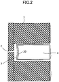
- Fig. 2 is a cross-sectional view illustrating the nozzle hole 2 and the tip end of the needle valve 4 enlarged.
- the nozzle hole 2 has a diameter of, for example, 0.1 mm and a length of, for example, 1 mm.
- the tip end surface of the needle valve 4 is formed in a recess shape so as not to interfere with the nozzle hole 2.
- a synthetic resin layer 20 set to have a thickness in the range of 0.1 mm to 0.5 mm (e.g., 0.2 mm) is also coated to cover the tip end of the needle valve 4 over a range of 2 mm in the axial direction.
- the synthetic resin layer 20 preferably has Young's modulus in a range from 5.6 to 8.3 Mpa, and is formed, for example, from perfluoroelastomers. If the Young's modulus of the synthetic resin layer 20 is lower than 5.6 MPa, the deformation restoration velocity of the compressed synthetic resin layer 20 is low. Thus, the nozzle hole 2 is blocked again by the tip end of the needle valve 4 before the deformation restoration is completed, which causes occurrence of the liquid leakage, and this is undesirable. By contrast, when the Young's modulus is higher than 8.3 MPa, the deformation restoration velocity of the compressed synthetic resin layer 20 is high, and the tip end of the needle valve 4 opens the nozzle hole 2 after the deformation restoration is completed. This unevenly widens the paint passage at a nozzle hole opening moment causing a difference in the paint application velocity. As a result, the straightness of the discharge liquid droplets is not maintained, and this is undesirable.
- the expansion rate of the synthetic resin layer 20 with respect to water-based paint thinner for cleaning be less than 3%, and it is desirable that the solvent resistance of the synthetic resin layer 20 is less than 5%.
- the synthetic resin layer 20 is formed as such at the tip end of the needle valve 4, the synthetic resin layer 20 is deformed to be crushed as illustrated in Fig. 3A .
- the nozzle hole 2 can be completely closed by the tip end of the needle valve 4 even when the tip surface of the needle valve 4 is tilted when the nozzle hole is in a closed state.
- FIG. 3A to 3C are cross-sectional views illustrating a change in the state of a nozzle hole and a tip end of the needle valve.
- FIG. 4 is a graph illustrating the displacement of the needle valve with respect to the elapsed time.
- This operation control is achieved by causing a non-illustrated controller (computer) to control the operation of the piezo-element 8 (driving mechanism), and specifically, is achieved by causing the controller to control the value of the voltage applied to the piezo-element 8.
- the state of Fig. 3A illustrates that the tip end of the needle valve 4 blocks the nozzle hole 2 when the synthetic resin layer 20 is crushed.
- the voltage applied to the piezo-element 8 is reduced to zero, and the needle valve 4 begins to retract at a predetermined velocity (e.g., 0.25 mm/ms or more) to a thickness of the synthetic resin layer 20 of, for example, 0.02 mm (Sq1 of FIG. 4 ).
- a predetermined velocity e.g. 0.25 mm/ms or more
- a thickness of the synthetic resin layer 20 of, for example, 0.02 mm (Sq1 of FIG. 4 ).
- the width of the paint passage is uniform at the nozzle hole opening moment, and as a result, the difference in the paint application velocity is eliminated, and the straightness of the discharge droplets is maintained.
- the increase rate of the applied voltage is kept low, and the needle valve 4 is further retracted to 0.03 mm at a lower velocity (e.g., less than 0.25 mm/ms) (Sq2 in Fig. 4 ). This makes the nozzle hole 2 completely open, as illustrated in Fig. 3C .
- the deformation of the synthetic resin layer 20 is restored, and when the nozzle hole 2 is closed, the applied voltage to the piezo-element 8 is gradually increased (Sq4 in Fig. 4 ), the needle valve 4 is gradually advanced (e.g., 0.1 mm/ms or less), and the nozzle hole 2 is closed by pressing the tip end of the needle valve 4 against the nozzle hole 2 to collapse (deform) the synthetic resin layer 20.
- the nozzle hole 2 is completely blocked by the synthetic resin layer 20 covering the tip end of the needle valve 4 even though the tip surface of the needle valve 4 is tilted.
- the needle valve 4 advances rapidly to close the nozzle hole 2, the paint around the nozzle hole 2 becomes turbulent, resulting in a turbulent flow.
- the paint is pushed, and discharged in this state, droplet separation of the paint is observed, and the painting accuracy is lowered.
- the needle valve 4 is controlled to be gradually advanced (e.g., 0.1 mm/ms or less).
- the synthetic resin layer 20 having a predetermined thickness is formed so as to cover the tip end of the needle valve 4. Accordingly, when the nozzle hole 2 is pressed by the tip end of the needle valve 4 to close the nozzle hole 2 while the tip surface of the needle valve 4 is tilted, the synthetic resin layer 20 covering the tip end of the needle valve 4 deforms to completely close the nozzle hole 2. In addition, when the nozzle hole 2 is opened, the retraction velocity of the needle valve 4 is increased higher than the deformation restoration velocity of the synthetic resin layer 20. As a result, it is possible to make the area (width) of the paint passage uniform at the nozzle hole opening moment, to eliminate the difference in discharge velocity, and to maintain the straightness of the discharge droplets. Further, when closing the nozzle hole 2, the turbulence around the nozzle hole 2 is reduced by controlling the advancing velocity of the needle valve 4 to be 0.1 mm/ms or less. Thus, it is possible to prevent a decrease in the painting accuracy.
- the synthetic resin layer 20 is made from, for example, a perfluoroelastomer, but is not limited to this example.
- Other synthetic resins with Young's modulus in the range of 5.6 to 8.3 Mpa can also be employed.
- a material suitable for a synthetic resin layer covering the tip end of the needle valve was verified.
- a perfluoroelastomer was used as a material of the aforementioned synthetic resin layer in Example 1
- Teflon (registered trademark) (PTFE) was used in Comparative Example 1
- silicon was used in Comparative Example 2.
- PTFE Teflon (registered trademark)
- Table 1 illustrates the conditions and results.
- Example 1 Comparative example 1 Comparative example 2 Young's modulus 5.6-8.3 8.7-10 2.9-3.8 Expansion rate of water-based paint thinner Superior Superior Inferior Solvent resistance (time) Superior Superior Inferior Wettability Superior Inferior Inferior Overall evaluation Superior Inferior Inferior
- Example 1 The results illustrated in Table 1 indicate that the perfluoroelastomer used in Example 1 is preferable as a material suitable for a synthetic resin layer covering the tip end of the needle valve, and the Young's modulus (MPa) is preferably 5.6 to 8.3.
- MPa Young's modulus
Landscapes
- Coating Apparatus (AREA)
- Nozzles (AREA)
Abstract

Description
- The disclosures discussed herein relate to a paint discharging nozzle and a method of controlling the paint discharging nozzle.
- In the automobile manufacturing process, for example, in a case of applying two color-painting (also called "2-tone painting") to the surface of the automobile body, paint is sprayed in the form of mist by a spray gun. In this case, the automobile body is masked, and paint is subsequently sprayed onto the masked surface of the automobile body by a spray gun, thereby forming a boundary line.
- However, the masking of the automobile body and removing the mask after the paint application is burdensome, and the work efficiency is degraded. Thus, attention has been attracted to a method of forming a boundary line using a paint discharging nozzle having a narrow discharging width without masking the automobile body.
- For example,
Patent Document 1 discloses an application device having a paint discharging nozzle. The application (print) device disclosed inPatent Document 1 includes a head array (ink jet nozzle head). The head array includes a plurality of paint discharging nozzles disposed in array to inject compressed air and apply high pressure to the ink tank filled with paint so as to discharge the paint to a remote area. - The application device further includes a linear rail for moving the head array back and forth in a linear manner, a multi-articulated robot for moving the linear rail by the robot arm, and a controller for controlling the driving of the robot and the ink jet nozzles. In the head array, a plurality of nozzles arranged in a horizontal array discharges each paint color from the nozzles while moving (scanning) on the linear rail in the array direction.
- Such an application device discharges the paint from a plurality of nozzles arranged in a linear manner along the scan direction, so that a film having a desired thickness can be formed by a small amount of scanning operation. This enables an application operation involving boundary lines at a high velocity without performing a masking process.
- In general, a nozzle tip end of the spray gun or the like is configured to open and close a
nozzle hole 51 formed at a nozzle tip, as illustrated in cross-sectional views inFigs. 5A and 5B , by advancing and retracting operations of aneedle 52 with respect to thenozzle hole 51. That is, when the nozzle is closed, theneedle 52 advances (is plugged) into thenozzle hole 51, and when the nozzle is opened, theneedle 52 is retracted from thenozzle hole 51. In the case of a spray gun, the diameter of thenozzle hole 51 is 0.3 mm, the diameter of theneedle 52 is 1.0 mm, and a tip end of the needle is reduced in diameter to form a sharp point. - In the case of the paint discharging nozzle, the nozzle hole is formed to be smaller (e.g., 0.1 mm in diameter) than the nozzle hole of the nozzle of the spray gun. Thus, it is difficult to machine the needle end to be inserted into the nozzle hole. As illustrated in the cross-sectional views of
Figs. 6A and 6B , aneedle 62 end is formed in a flat form, and when the nozzle is closed, an end surface of theneedle 62 is touched against thenozzle hole 61 to block thenozzle hole 61. - In addition, paint is highly viscous and has a high resistance to fluid flow.
Patent Document 2 discloses a paint discharging nozzle capable of preventing paint at a nozzle tip end from being clogged by forming a large gap between a periphery of the needle tip end and an inner wall of the nozzle (a paint passage), and securing a large needle stroke. - However, when the width (area) of the paint passage and the needle stroke are increased, the installation accuracy is likely to vary, and as illustrated in
Fig. 7 , the end surface of theneedle 62 is tilted when the nozzle is closed. This results in forming a gap between theneedle 62 and thenozzle hole 61, resulting in a risk of liquid leakage. When such a liquid leakage has occurred, the discharged liquid is attracted by the surface tension of the leaked liquid, and the straightness of the discharged liquid is hindered. - Further, when the liquid leakage has occurred, a difference in the width of the paint passage has occurred at the
nozzle hole 61 caused by the tilted end surface of theneedle 62 with respect to thenozzle hole 61. This results in a difference in the discharge velocity, splitting of the droplets after being discharged, and making the liquid passage non-uniform, thereby decreasing in the liquid application accuracy. - It is desirable to provide a paint discharging nozzle and a method of controlling the paint discharging nozzle, wherein the paint discharging nozzle can prevent a liquid leakage when the nozzle hole is in a closed state, and obtain a stable liquid application accuracy when the nozzle is opened.
-
- [Patent Document 1]
Japanese Patent Application Laid-Open No. 2015-027636 - [Patent Document 2]
Japanese Patent Application Laid-Open No. 2004-142382 - According to an embodiment of the present invention, a paint discharging nozzle designed for discharging paint supplied at a predetermined pressure is provided. The paint discharging nozzle includes
- a housing having a nozzle hole through which paint is discharged;
- a paint chamber configured to supply paint to the nozzle hole;
- a needle valve disposed in the paint chamber, the needle valve having a tip end configured to close or open the nozzle hole;
- a driving mechanism configured to drive the needle valve to advance toward and retract from the nozzle hole; and
- a synthetic resin layer formed to cover the tip end of the needle valve.
- According to an embodiment of the present invention, when the needle valve opens the nozzle hole, it is preferable that the driving mechanism cause the needle valve to retract from the nozzle hole at a velocity higher than a deformation restoration velocity of the synthetic resin layer. In addition, it is preferable that the Young's modulus of the synthetic resin layer be set to be in the range of 5.6 to 8.3 MPa.
- As described above, a synthetic resin layer having a predetermined thickness is formed to cover a tip end of the needle valve. Accordingly, when the nozzle hole is pressed by the tip end of the needle valve, and the tip surface of the needle valve is tilted, the synthetic resin layer deforms to completely close the nozzle hole.
- Further, according to another embodiment of the present invention, a method of controlling a paint discharging nozzle is provided. The method includes
- closing a nozzle hole with a tip end of a needle valve by an advance operation of the needle valve toward the nozzle hole through which paint is discharged; and
- opening the nozzle hole by a retraction operation of the needle valve from the nozzle hole,
- wherein in the opening, a retraction velocity of the needle valve is higher than a deformation restoration velocity of a synthetic resin layer covering the tip end of the needle valve.
- According to another embodiment of the present invention, when opening the nozzle hole, the retraction velocity of the needle valve is made higher than the deformation restoration velocity of the synthetic resin layer, thereby making the width (area) of the paint passage uniform at a nozzle hole opening moment, by eliminating the difference in discharge velocity, and by maintaining the straightness of discharged droplets.
- According to the present invention, it is possible to provide a paint discharging nozzle capable of executing a control method of preventing the occurrence of liquid leakage when the nozzle hole is in a closed state and obtaining stable paint application accuracy when the nozzle is opened.
-
-
Fig. 1 is a block diagram schematically illustrating a main configuration of a paint discharging nozzle according to the present embodiment; -
FIG. 2 is a cross-sectional view illustrating an enlarged view of a nozzle hole and a tip end of a needle valve; -
Figs. 3A to 3C are cross-sectional views illustrating a change in the state of a nozzle hole and a tip end of a needle valve; -
FIG. 4 is a graph illustrating the displacement of a needle valve with respect to the elapsed time; -
Figs. 5A and 5B are cross-sectional views illustrating opening and closing operations of the nozzle tip end of a spray gun; -
Figs. 6A and 6B are cross-sectional views illustrating opening and closing operations of the nozzle tip end of the paint discharging nozzle; and -
Fig. 7 is a cross-sectional view illustrating a problem in the paint discharging nozzle. - Hereinafter, embodiments of the paint discharging nozzle according to the present invention and the control method of the paint discharging nozzle will be described with reference to the accompanying drawings. The paint discharging nozzle according to the present embodiment is used, for example, in an application device in an automobile manufacturing line, and discharges paint for example, 2-tone painting (having a boundary line with the other color of painting).
-
Fig. 1 is a block diagram schematically illustrating a main configuration of apaint discharging nozzle 100 according to the present embodiment. Thepaint discharging nozzle 100 includes anozzle hole 2 provided in the front surface of thehousing 1, apaint chamber 3 formed in thehousing 1 to supply paint to thenozzle hole 2, aneedle valve 4 located in thepaint chamber 3 and having a tip end to close or open thenozzle hole 2, and a piezo-element 8 as a driving mechanism fixed to a rear side of theneedle valve 4. - A
paint input passage 5 is connected to one side of thepaint chamber 3, and apaint collection passage 6 is connected to the opposite side of thepaint chamber 3. Thepaint chamber 3 is constantly supplied with the paint from a paint supply unit (not illustrated) through thepaint input passage 5, and is collected from thepaint collection passage 6. Thus, the paint is filled without any paint stagnation. When thenozzle hole 2 is in a closed state, a predetermined pressure is maintained in thepaint chamber 3 by adjusting the flow rate of the paint from thepaint input passage 5. - When a predetermined voltage is applied by a voltage application unit (not illustrated), the piezo-
element 8 changes the axial length of theneedle valve 4 and moves (advances) theneedle valve 4 toward thenozzle hole 2. This closing procedure allows the tip end of theneedle valve 4 to close the nozzle hole 2 (the nozzle hole is in a closed state). - When the applied voltage is lowered from the nozzle closed state, the piezo-
element 8 deforms theneedle valve 4 away from the nozzle hole 2 (the nozzle hole is in an open state). When thenozzle hole 2 is opened according to this opening procedure, thedroplets 17 are discharged from thenozzle hole 2 toward a workpiece W by the pressure inside thepaint chamber 3 as illustrated inFig. 1 . - The piezo-
element 8 is housed in a drivingmechanism housing space 9 formed in thehousing 1. The drivingmechanism housing space 9 is separated from thepaint chamber 3 by double O-rings paint chamber 3 does not flow into the drivingmechanism housing space 9. -
Fig. 2 is a cross-sectional view illustrating thenozzle hole 2 and the tip end of theneedle valve 4 enlarged. Thenozzle hole 2 has a diameter of, for example, 0.1 mm and a length of, for example, 1 mm. The tip end surface of theneedle valve 4 is formed in a recess shape so as not to interfere with thenozzle hole 2. Asynthetic resin layer 20 set to have a thickness in the range of 0.1 mm to 0.5 mm (e.g., 0.2 mm) is also coated to cover the tip end of theneedle valve 4 over a range of 2 mm in the axial direction. - The
synthetic resin layer 20 preferably has Young's modulus in a range from 5.6 to 8.3 Mpa, and is formed, for example, from perfluoroelastomers. If the Young's modulus of thesynthetic resin layer 20 is lower than 5.6 MPa, the deformation restoration velocity of the compressedsynthetic resin layer 20 is low. Thus, thenozzle hole 2 is blocked again by the tip end of theneedle valve 4 before the deformation restoration is completed, which causes occurrence of the liquid leakage, and this is undesirable. By contrast, when the Young's modulus is higher than 8.3 MPa, the deformation restoration velocity of the compressedsynthetic resin layer 20 is high, and the tip end of theneedle valve 4 opens thenozzle hole 2 after the deformation restoration is completed. This unevenly widens the paint passage at a nozzle hole opening moment causing a difference in the paint application velocity. As a result, the straightness of the discharge liquid droplets is not maintained, and this is undesirable. - In addition, it is desirable that the expansion rate of the
synthetic resin layer 20 with respect to water-based paint thinner for cleaning be less than 3%, and it is desirable that the solvent resistance of thesynthetic resin layer 20 is less than 5%. When thesynthetic resin layer 20 is formed as such at the tip end of theneedle valve 4, thesynthetic resin layer 20 is deformed to be crushed as illustrated inFig. 3A . As a result, thenozzle hole 2 can be completely closed by the tip end of theneedle valve 4 even when the tip surface of theneedle valve 4 is tilted when the nozzle hole is in a closed state. - Next, an operation control for discharging the paint using the
paint discharging nozzle 100 configured as described above will be described with reference toFigs. 3A to 3C , andFig. 4 .Figs. 3A to 3C are cross-sectional views illustrating a change in the state of a nozzle hole and a tip end of the needle valve.FIG. 4 is a graph illustrating the displacement of the needle valve with respect to the elapsed time. This operation control is achieved by causing a non-illustrated controller (computer) to control the operation of the piezo-element 8 (driving mechanism), and specifically, is achieved by causing the controller to control the value of the voltage applied to the piezo-element 8. - As described above, the state of
Fig. 3A (i.e., thenozzle hole 2 is completely closed) illustrates that the tip end of theneedle valve 4 blocks thenozzle hole 2 when thesynthetic resin layer 20 is crushed. From this state, the voltage applied to the piezo-element 8 is reduced to zero, and theneedle valve 4 begins to retract at a predetermined velocity (e.g., 0.25 mm/ms or more) to a thickness of thesynthetic resin layer 20 of, for example, 0.02 mm (Sq1 ofFIG. 4 ). This causes theneedle valve 4 to retract and thenozzle hole 2 to open prior to completion of the deformation restoration of thesynthetic resin layer 20, as illustrated inFig. 3B . Further, the width of the paint passage is uniform at the nozzle hole opening moment, and as a result, the difference in the paint application velocity is eliminated, and the straightness of the discharge droplets is maintained. - When the retracted distance of the
needle valve 4 exceeds 0.02 mm, the increase rate of the applied voltage is kept low, and theneedle valve 4 is further retracted to 0.03 mm at a lower velocity (e.g., less than 0.25 mm/ms) (Sq2 inFig. 4 ). This makes thenozzle hole 2 completely open, as illustrated inFig. 3C . - After opening the nozzle hole 2 (Sq3 in
Fig. 4 ), the deformation of thesynthetic resin layer 20 is restored, and when thenozzle hole 2 is closed, the applied voltage to the piezo-element 8 is gradually increased (Sq4 inFig. 4 ), theneedle valve 4 is gradually advanced (e.g., 0.1 mm/ms or less), and thenozzle hole 2 is closed by pressing the tip end of theneedle valve 4 against thenozzle hole 2 to collapse (deform) thesynthetic resin layer 20. Thus, thenozzle hole 2 is completely blocked by thesynthetic resin layer 20 covering the tip end of theneedle valve 4 even though the tip surface of theneedle valve 4 is tilted. - When the
needle valve 4 advances rapidly to close thenozzle hole 2, the paint around thenozzle hole 2 becomes turbulent, resulting in a turbulent flow. When the paint is pushed, and discharged in this state, droplet separation of the paint is observed, and the painting accuracy is lowered. Thus, according to the present embodiment, as described above, theneedle valve 4 is controlled to be gradually advanced (e.g., 0.1 mm/ms or less). - As described above, according to the embodiment of the present invention, the
synthetic resin layer 20 having a predetermined thickness is formed so as to cover the tip end of theneedle valve 4. Accordingly, when thenozzle hole 2 is pressed by the tip end of theneedle valve 4 to close thenozzle hole 2 while the tip surface of theneedle valve 4 is tilted, thesynthetic resin layer 20 covering the tip end of theneedle valve 4 deforms to completely close thenozzle hole 2. In addition, when thenozzle hole 2 is opened, the retraction velocity of theneedle valve 4 is increased higher than the deformation restoration velocity of thesynthetic resin layer 20. As a result, it is possible to make the area (width) of the paint passage uniform at the nozzle hole opening moment, to eliminate the difference in discharge velocity, and to maintain the straightness of the discharge droplets. Further, when closing thenozzle hole 2, the turbulence around thenozzle hole 2 is reduced by controlling the advancing velocity of theneedle valve 4 to be 0.1 mm/ms or less. Thus, it is possible to prevent a decrease in the painting accuracy. - According to the above-described embodiment, the
synthetic resin layer 20 is made from, for example, a perfluoroelastomer, but is not limited to this example. Other synthetic resins with Young's modulus in the range of 5.6 to 8.3 Mpa can also be employed. - In this example, a material suitable for a synthetic resin layer covering the tip end of the needle valve was verified. A perfluoroelastomer was used as a material of the aforementioned synthetic resin layer in Example 1, Teflon (registered trademark) (PTFE) was used in Comparative Example 1, and silicon was used in Comparative Example 2. Each material was applied to the synthetic resin layer according to the present embodiment, and the expansion rate of the water-based paint thinner for cleaning, the solvent resistance (time), and the presence or absence of leakage were evaluated. Table 1 illustrates the conditions and results.
[Table 1] Example 1 Comparative example 1 Comparative example 2 Young's modulus 5.6-8.3 8.7-10 2.9-3.8 Expansion rate of water-based paint thinner Superior Superior Inferior Solvent resistance (time) Superior Superior Inferior Wettability Superior Inferior Inferior Overall evaluation Superior Inferior Inferior - The results illustrated in Table 1 indicate that the perfluoroelastomer used in Example 1 is preferable as a material suitable for a synthetic resin layer covering the tip end of the needle valve, and the Young's modulus (MPa) is preferably 5.6 to 8.3.
Claims (3)
- A paint discharging nozzle designed for discharging paint supplied at a predetermined pressure, the paint discharging nozzle comprising:a housing having a nozzle hole through which paint is discharged;a paint chamber configured to supply paint to the nozzle hole;a needle valve disposed in the paint chamber, the needle valve having a tip end configured to close or open the nozzle hole;a driving mechanism configured to drive the needle valve to advance toward and retract from the nozzle hole; anda synthetic resin layer formed to cover the tip end of the needle valve.
- The paint discharging nozzle according to claim 1, wherein
when the needle valve opens the nozzle hole, the driving mechanism causes the needle valve to retract from the nozzle hole at a velocity higher than a deformation restoration velocity of the synthetic resin layer. - A method of controlling a paint discharging nozzle, the method comprising:closing a nozzle hole with a tip end of a needle valve by an advance operation of the needle valve toward the nozzle hole through which paint is discharged; andopening the nozzle hole by a retraction operation of the needle valve from the nozzle hole,wherein in the opening, a retraction velocity of the needle valve is higher than a deformation restoration velocity of a synthetic resin layer covering the tip end of the needle valve.
Applications Claiming Priority (1)
| Application Number | Priority Date | Filing Date | Title |
|---|---|---|---|
| JP2020173140A JP7553315B2 (en) | 2020-10-14 | 2020-10-14 | Paint injection nozzle and control method thereof |
Publications (2)
| Publication Number | Publication Date |
|---|---|
| EP3984649A1 true EP3984649A1 (en) | 2022-04-20 |
| EP3984649B1 EP3984649B1 (en) | 2025-03-05 |
Family
ID=78087130
Family Applications (1)
| Application Number | Title | Priority Date | Filing Date |
|---|---|---|---|
| EP21201839.4A Active EP3984649B1 (en) | 2020-10-14 | 2021-10-11 | Paint discharging nozzle and method of controlling paint discharging nozzle |
Country Status (3)
| Country | Link |
|---|---|
| US (1) | US11712704B2 (en) |
| EP (1) | EP3984649B1 (en) |
| JP (1) | JP7553315B2 (en) |
Cited By (1)
| Publication number | Priority date | Publication date | Assignee | Title |
|---|---|---|---|---|
| WO2023126709A1 (en) * | 2021-12-28 | 2023-07-06 | Ricoh Company, Ltd. | Liquid discharge head and liquid discharge apparatus |
Families Citing this family (5)
| Publication number | Priority date | Publication date | Assignee | Title |
|---|---|---|---|---|
| JP7825466B2 (en) | 2022-03-11 | 2026-03-06 | 株式会社リコー | Liquid ejection head and liquid ejection device |
| JP2024130564A (en) | 2023-03-15 | 2024-09-30 | 株式会社リコー | LIQUID EJECTION MODULE, LIQUID EJECTION HEAD, AND LIQUID EJECTION APPARATUS |
| JP2024130575A (en) | 2023-03-15 | 2024-09-30 | 株式会社リコー | Liquid ejection head and liquid ejection device |
| JP2025088418A (en) | 2023-11-30 | 2025-06-11 | 株式会社リコー | Liquid discharge unit, printing device, printing method |
| JP7551952B1 (en) * | 2024-01-30 | 2024-09-17 | 株式会社リコー | Painting Equipment |
Citations (4)
| Publication number | Priority date | Publication date | Assignee | Title |
|---|---|---|---|---|
| JP2004142382A (en) | 2002-10-28 | 2004-05-20 | Lac:Kk | Ink jet nozzle |
| WO2012058373A2 (en) * | 2010-10-27 | 2012-05-03 | Matthews Resources, Inc. | Valve jet printer with inert plunger tip |
| JP2015027636A (en) | 2013-07-04 | 2015-02-12 | 株式会社エルエーシー | Printing apparatus |
| US20190337005A1 (en) * | 2016-12-14 | 2019-11-07 | Dürr Systems Ag | Print head for the application of a coating agent on a component |
Family Cites Families (13)
| Publication number | Priority date | Publication date | Assignee | Title |
|---|---|---|---|---|
| JPS6010912B2 (en) | 1978-10-04 | 1985-03-20 | キヤノン株式会社 | recording head |
| JPS58102774A (en) | 1981-12-14 | 1983-06-18 | Nec Corp | Ink jet recording method and its device |
| DE602007007212D1 (en) * | 2007-09-14 | 2010-07-29 | Delphi Tech Holding Sarl | Injection control system |
| JP5914064B2 (en) | 2012-03-12 | 2016-05-11 | 株式会社エルエーシー | Printing device |
| JP6079301B2 (en) | 2013-02-28 | 2017-02-15 | 株式会社リコー | Image forming apparatus and head drive control method |
| JP6842152B2 (en) * | 2016-05-31 | 2021-03-17 | 武蔵エンジニアリング株式会社 | Liquid material discharge device, its coating device and coating method |
| JP6834765B2 (en) | 2017-05-16 | 2021-02-24 | 株式会社リコー | Inkjet printer and 3D printing method |
| JP7271956B2 (en) | 2018-01-16 | 2023-05-12 | 株式会社リコー | Device for ejecting valve type nozzle and liquid |
| JP2019150798A (en) * | 2018-03-06 | 2019-09-12 | パナソニックIpマネジメント株式会社 | Coating method and device of liquid material |
| US11148364B2 (en) | 2018-07-19 | 2021-10-19 | Ricoh Company, Ltd. | Three dimensional modeling apparatus |
| EP3599102B1 (en) | 2018-07-24 | 2022-11-09 | Ricoh Company, Ltd. | Liquid jet device |
| JP7310404B2 (en) * | 2018-08-01 | 2023-07-19 | 株式会社リコー | Liquid ejection head, head unit, device for ejecting liquid, and liquid ejection method |
| US10987927B2 (en) | 2018-08-01 | 2021-04-27 | Ricoh Company, Ltd. | Liquid discharge head, head unit, apparatus for discharging liquid, and liquid discharging method |
-
2020
- 2020-10-14 JP JP2020173140A patent/JP7553315B2/en active Active
-
2021
- 2021-10-11 EP EP21201839.4A patent/EP3984649B1/en active Active
- 2021-10-13 US US17/499,872 patent/US11712704B2/en active Active
Patent Citations (4)
| Publication number | Priority date | Publication date | Assignee | Title |
|---|---|---|---|---|
| JP2004142382A (en) | 2002-10-28 | 2004-05-20 | Lac:Kk | Ink jet nozzle |
| WO2012058373A2 (en) * | 2010-10-27 | 2012-05-03 | Matthews Resources, Inc. | Valve jet printer with inert plunger tip |
| JP2015027636A (en) | 2013-07-04 | 2015-02-12 | 株式会社エルエーシー | Printing apparatus |
| US20190337005A1 (en) * | 2016-12-14 | 2019-11-07 | Dürr Systems Ag | Print head for the application of a coating agent on a component |
Cited By (1)
| Publication number | Priority date | Publication date | Assignee | Title |
|---|---|---|---|---|
| WO2023126709A1 (en) * | 2021-12-28 | 2023-07-06 | Ricoh Company, Ltd. | Liquid discharge head and liquid discharge apparatus |
Also Published As
| Publication number | Publication date |
|---|---|
| JP7553315B2 (en) | 2024-09-18 |
| US11712704B2 (en) | 2023-08-01 |
| JP2022064482A (en) | 2022-04-26 |
| EP3984649B1 (en) | 2025-03-05 |
| US20220111405A1 (en) | 2022-04-14 |
Similar Documents
| Publication | Publication Date | Title |
|---|---|---|
| EP3984649B1 (en) | Paint discharging nozzle and method of controlling paint discharging nozzle | |
| TWI610824B (en) | Liquid material discharging method and device | |
| KR101801224B1 (en) | Droplet discharge device and method | |
| JP7310404B2 (en) | Liquid ejection head, head unit, device for ejecting liquid, and liquid ejection method | |
| DE69320766T2 (en) | Inkjet printhead and its manufacturing process | |
| WO2013013983A1 (en) | Print head for an ink jet printer | |
| EP1992465B1 (en) | Spray head | |
| WO2019181812A1 (en) | Liquid material ejecting apparatus | |
| JP2000153205A (en) | Coating apparatus and manufacturing method of coating member, and manufacturing apparatus and manufacturing method of color filter | |
| JP5856332B1 (en) | Micro fluid discharge method and micro fluid dispenser | |
| CN113117918A (en) | Fluid injector | |
| JP6177291B2 (en) | Droplet ejection apparatus and method | |
| KR20080055593A (en) | Applicator | |
| JP6285510B2 (en) | Liquid material discharge apparatus and method | |
| CN120787181A (en) | Inkjet coating method | |
| HK1228836A1 (en) | Droplet discharge device and method | |
| CN116890534A (en) | Printing head and coating device comprising a maintenance circuit | |
| HK40033091A (en) | Liquid material ejecting apparatus | |
| HK1193377B (en) | Droplet discharge device and method | |
| HK1138534B (en) | Method and apparatus for discharging liquid material | |
| JP2000024568A (en) | Liquid material coating equipment | |
| HK1228836B (en) | Droplet discharge device and method |
Legal Events
| Date | Code | Title | Description |
|---|---|---|---|
| PUAI | Public reference made under article 153(3) epc to a published international application that has entered the european phase |
Free format text: ORIGINAL CODE: 0009012 |
|
| STAA | Information on the status of an ep patent application or granted ep patent |
Free format text: STATUS: REQUEST FOR EXAMINATION WAS MADE |
|
| 17P | Request for examination filed |
Effective date: 20211011 |
|
| AK | Designated contracting states |
Kind code of ref document: A1 Designated state(s): AL AT BE BG CH CY CZ DE DK EE ES FI FR GB GR HR HU IE IS IT LI LT LU LV MC MK MT NL NO PL PT RO RS SE SI SK SM TR |
|
| STAA | Information on the status of an ep patent application or granted ep patent |
Free format text: STATUS: EXAMINATION IS IN PROGRESS |
|
| 17Q | First examination report despatched |
Effective date: 20230612 |
|
| RIC1 | Information provided on ipc code assigned before grant |
Ipc: B05B 15/58 20180101ALN20240207BHEP Ipc: B05C 5/02 20060101ALI20240207BHEP Ipc: B05B 1/30 20060101AFI20240207BHEP |
|
| RIN1 | Information on inventor provided before grant (corrected) |
Inventor name: MURAI, SHUSEI Inventor name: OZAWA, SHOHEI Inventor name: MARUYAMA, KEIKO |
|
| GRAP | Despatch of communication of intention to grant a patent |
Free format text: ORIGINAL CODE: EPIDOSNIGR1 |
|
| STAA | Information on the status of an ep patent application or granted ep patent |
Free format text: STATUS: GRANT OF PATENT IS INTENDED |
|
| RIC1 | Information provided on ipc code assigned before grant |
Ipc: B05B 15/58 20180101ALN20241018BHEP Ipc: B05C 5/02 20060101ALI20241018BHEP Ipc: B05B 1/30 20060101AFI20241018BHEP |
|
| INTG | Intention to grant announced |
Effective date: 20241113 |
|
| GRAS | Grant fee paid |
Free format text: ORIGINAL CODE: EPIDOSNIGR3 |
|
| GRAA | (expected) grant |
Free format text: ORIGINAL CODE: 0009210 |
|
| STAA | Information on the status of an ep patent application or granted ep patent |
Free format text: STATUS: THE PATENT HAS BEEN GRANTED |
|
| P01 | Opt-out of the competence of the unified patent court (upc) registered |
Free format text: CASE NUMBER: APP_440/2025 Effective date: 20250106 |
|
| AK | Designated contracting states |
Kind code of ref document: B1 Designated state(s): AL AT BE BG CH CY CZ DE DK EE ES FI FR GB GR HR HU IE IS IT LI LT LU LV MC MK MT NL NO PL PT RO RS SE SI SK SM TR |
|
| REG | Reference to a national code |
Ref country code: GB Ref legal event code: FG4D |
|
| REG | Reference to a national code |
Ref country code: CH Ref legal event code: EP |
|
| REG | Reference to a national code |
Ref country code: IE Ref legal event code: FG4D |
|
| REG | Reference to a national code |
Ref country code: DE Ref legal event code: R096 Ref document number: 602021027068 Country of ref document: DE |
|
| PG25 | Lapsed in a contracting state [announced via postgrant information from national office to epo] |
Ref country code: RS Free format text: LAPSE BECAUSE OF FAILURE TO SUBMIT A TRANSLATION OF THE DESCRIPTION OR TO PAY THE FEE WITHIN THE PRESCRIBED TIME-LIMIT Effective date: 20250605 |
|
| PG25 | Lapsed in a contracting state [announced via postgrant information from national office to epo] |
Ref country code: FI Free format text: LAPSE BECAUSE OF FAILURE TO SUBMIT A TRANSLATION OF THE DESCRIPTION OR TO PAY THE FEE WITHIN THE PRESCRIBED TIME-LIMIT Effective date: 20250305 |
|
| REG | Reference to a national code |
Ref country code: NL Ref legal event code: MP Effective date: 20250305 |
|
| PG25 | Lapsed in a contracting state [announced via postgrant information from national office to epo] |
Ref country code: ES Free format text: LAPSE BECAUSE OF FAILURE TO SUBMIT A TRANSLATION OF THE DESCRIPTION OR TO PAY THE FEE WITHIN THE PRESCRIBED TIME-LIMIT Effective date: 20250305 |
|
| REG | Reference to a national code |
Ref country code: LT Ref legal event code: MG9D |
|
| PG25 | Lapsed in a contracting state [announced via postgrant information from national office to epo] |
Ref country code: NO Free format text: LAPSE BECAUSE OF FAILURE TO SUBMIT A TRANSLATION OF THE DESCRIPTION OR TO PAY THE FEE WITHIN THE PRESCRIBED TIME-LIMIT Effective date: 20250605 |
|
| PG25 | Lapsed in a contracting state [announced via postgrant information from national office to epo] |
Ref country code: HR Free format text: LAPSE BECAUSE OF FAILURE TO SUBMIT A TRANSLATION OF THE DESCRIPTION OR TO PAY THE FEE WITHIN THE PRESCRIBED TIME-LIMIT Effective date: 20250305 |
|
| PG25 | Lapsed in a contracting state [announced via postgrant information from national office to epo] |
Ref country code: LV Free format text: LAPSE BECAUSE OF FAILURE TO SUBMIT A TRANSLATION OF THE DESCRIPTION OR TO PAY THE FEE WITHIN THE PRESCRIBED TIME-LIMIT Effective date: 20250305 |
|
| PG25 | Lapsed in a contracting state [announced via postgrant information from national office to epo] |
Ref country code: GR Free format text: LAPSE BECAUSE OF FAILURE TO SUBMIT A TRANSLATION OF THE DESCRIPTION OR TO PAY THE FEE WITHIN THE PRESCRIBED TIME-LIMIT Effective date: 20250606 Ref country code: BG Free format text: LAPSE BECAUSE OF FAILURE TO SUBMIT A TRANSLATION OF THE DESCRIPTION OR TO PAY THE FEE WITHIN THE PRESCRIBED TIME-LIMIT Effective date: 20250305 |
|
| REG | Reference to a national code |
Ref country code: AT Ref legal event code: MK05 Ref document number: 1772450 Country of ref document: AT Kind code of ref document: T Effective date: 20250305 |
|
| PG25 | Lapsed in a contracting state [announced via postgrant information from national office to epo] |
Ref country code: NL Free format text: LAPSE BECAUSE OF FAILURE TO SUBMIT A TRANSLATION OF THE DESCRIPTION OR TO PAY THE FEE WITHIN THE PRESCRIBED TIME-LIMIT Effective date: 20250305 |
|
| PG25 | Lapsed in a contracting state [announced via postgrant information from national office to epo] |
Ref country code: SE Free format text: LAPSE BECAUSE OF FAILURE TO SUBMIT A TRANSLATION OF THE DESCRIPTION OR TO PAY THE FEE WITHIN THE PRESCRIBED TIME-LIMIT Effective date: 20250305 |
|
| PG25 | Lapsed in a contracting state [announced via postgrant information from national office to epo] |
Ref country code: SM Free format text: LAPSE BECAUSE OF FAILURE TO SUBMIT A TRANSLATION OF THE DESCRIPTION OR TO PAY THE FEE WITHIN THE PRESCRIBED TIME-LIMIT Effective date: 20250305 |
|
| PG25 | Lapsed in a contracting state [announced via postgrant information from national office to epo] |
Ref country code: PT Free format text: LAPSE BECAUSE OF FAILURE TO SUBMIT A TRANSLATION OF THE DESCRIPTION OR TO PAY THE FEE WITHIN THE PRESCRIBED TIME-LIMIT Effective date: 20250707 |
|
| PG25 | Lapsed in a contracting state [announced via postgrant information from national office to epo] |
Ref country code: IT Free format text: LAPSE BECAUSE OF FAILURE TO SUBMIT A TRANSLATION OF THE DESCRIPTION OR TO PAY THE FEE WITHIN THE PRESCRIBED TIME-LIMIT Effective date: 20250305 Ref country code: PL Free format text: LAPSE BECAUSE OF FAILURE TO SUBMIT A TRANSLATION OF THE DESCRIPTION OR TO PAY THE FEE WITHIN THE PRESCRIBED TIME-LIMIT Effective date: 20250305 |
|
| PG25 | Lapsed in a contracting state [announced via postgrant information from national office to epo] |
Ref country code: AT Free format text: LAPSE BECAUSE OF FAILURE TO SUBMIT A TRANSLATION OF THE DESCRIPTION OR TO PAY THE FEE WITHIN THE PRESCRIBED TIME-LIMIT Effective date: 20250305 |
|
| PG25 | Lapsed in a contracting state [announced via postgrant information from national office to epo] |
Ref country code: CZ Free format text: LAPSE BECAUSE OF FAILURE TO SUBMIT A TRANSLATION OF THE DESCRIPTION OR TO PAY THE FEE WITHIN THE PRESCRIBED TIME-LIMIT Effective date: 20250305 Ref country code: EE Free format text: LAPSE BECAUSE OF FAILURE TO SUBMIT A TRANSLATION OF THE DESCRIPTION OR TO PAY THE FEE WITHIN THE PRESCRIBED TIME-LIMIT Effective date: 20250305 |
|
| PG25 | Lapsed in a contracting state [announced via postgrant information from national office to epo] |
Ref country code: RO Free format text: LAPSE BECAUSE OF FAILURE TO SUBMIT A TRANSLATION OF THE DESCRIPTION OR TO PAY THE FEE WITHIN THE PRESCRIBED TIME-LIMIT Effective date: 20250305 |
|
| PG25 | Lapsed in a contracting state [announced via postgrant information from national office to epo] |
Ref country code: SK Free format text: LAPSE BECAUSE OF FAILURE TO SUBMIT A TRANSLATION OF THE DESCRIPTION OR TO PAY THE FEE WITHIN THE PRESCRIBED TIME-LIMIT Effective date: 20250305 |
|
| PG25 | Lapsed in a contracting state [announced via postgrant information from national office to epo] |
Ref country code: IS Free format text: LAPSE BECAUSE OF FAILURE TO SUBMIT A TRANSLATION OF THE DESCRIPTION OR TO PAY THE FEE WITHIN THE PRESCRIBED TIME-LIMIT Effective date: 20250705 |
|
| REG | Reference to a national code |
Ref country code: DE Ref legal event code: R097 Ref document number: 602021027068 Country of ref document: DE |
|
| PGFP | Annual fee paid to national office [announced via postgrant information from national office to epo] |
Ref country code: DE Payment date: 20251021 Year of fee payment: 5 |
|
| PGFP | Annual fee paid to national office [announced via postgrant information from national office to epo] |
Ref country code: GB Payment date: 20251022 Year of fee payment: 5 |
|
| PLBE | No opposition filed within time limit |
Free format text: ORIGINAL CODE: 0009261 |
|
| STAA | Information on the status of an ep patent application or granted ep patent |
Free format text: STATUS: NO OPPOSITION FILED WITHIN TIME LIMIT |
|
| PG25 | Lapsed in a contracting state [announced via postgrant information from national office to epo] |
Ref country code: DK Free format text: LAPSE BECAUSE OF FAILURE TO SUBMIT A TRANSLATION OF THE DESCRIPTION OR TO PAY THE FEE WITHIN THE PRESCRIBED TIME-LIMIT Effective date: 20250305 |
|
| REG | Reference to a national code |
Ref country code: CH Ref legal event code: L10 Free format text: ST27 STATUS EVENT CODE: U-0-0-L10-L00 (AS PROVIDED BY THE NATIONAL OFFICE) Effective date: 20260114 |
|
| PGFP | Annual fee paid to national office [announced via postgrant information from national office to epo] |
Ref country code: FR Payment date: 20251030 Year of fee payment: 5 |
|
| 26N | No opposition filed |
Effective date: 20251208 |