EP3984574B1 - Syringe with compressible spacer - Google Patents
Syringe with compressible spacer Download PDFInfo
- Publication number
- EP3984574B1 EP3984574B1 EP20201811.5A EP20201811A EP3984574B1 EP 3984574 B1 EP3984574 B1 EP 3984574B1 EP 20201811 A EP20201811 A EP 20201811A EP 3984574 B1 EP3984574 B1 EP 3984574B1
- Authority
- EP
- European Patent Office
- Prior art keywords
- spacer
- syringe
- barrel
- syringe barrel
- liquid
- Prior art date
- Legal status (The legal status is an assumption and is not a legal conclusion. Google has not performed a legal analysis and makes no representation as to the accuracy of the status listed.)
- Active
Links
Images


Classifications
-
- A—HUMAN NECESSITIES
- A61—MEDICAL OR VETERINARY SCIENCE; HYGIENE
- A61M—DEVICES FOR INTRODUCING MEDIA INTO, OR ONTO, THE BODY; DEVICES FOR TRANSDUCING BODY MEDIA OR FOR TAKING MEDIA FROM THE BODY; DEVICES FOR PRODUCING OR ENDING SLEEP OR STUPOR
- A61M5/00—Devices for bringing media into the body in a subcutaneous, intra-vascular or intramuscular way; Accessories therefor, e.g. filling or cleaning devices, arm-rests
- A61M5/178—Syringes
- A61M5/31—Details
- A61M5/315—Pistons; Piston-rods; Guiding, blocking or restricting the movement of the rod or piston; Appliances on the rod for facilitating dosing ; Dosing mechanisms
- A61M5/31501—Means for blocking or restricting the movement of the rod or piston
-
- A—HUMAN NECESSITIES
- A61—MEDICAL OR VETERINARY SCIENCE; HYGIENE
- A61M—DEVICES FOR INTRODUCING MEDIA INTO, OR ONTO, THE BODY; DEVICES FOR TRANSDUCING BODY MEDIA OR FOR TAKING MEDIA FROM THE BODY; DEVICES FOR PRODUCING OR ENDING SLEEP OR STUPOR
- A61M5/00—Devices for bringing media into the body in a subcutaneous, intra-vascular or intramuscular way; Accessories therefor, e.g. filling or cleaning devices, arm-rests
- A61M5/178—Syringes
- A61M5/31—Details
- A61M5/315—Pistons; Piston-rods; Guiding, blocking or restricting the movement of the rod or piston; Appliances on the rod for facilitating dosing ; Dosing mechanisms
- A61M5/31525—Dosing
-
- A—HUMAN NECESSITIES
- A61—MEDICAL OR VETERINARY SCIENCE; HYGIENE
- A61M—DEVICES FOR INTRODUCING MEDIA INTO, OR ONTO, THE BODY; DEVICES FOR TRANSDUCING BODY MEDIA OR FOR TAKING MEDIA FROM THE BODY; DEVICES FOR PRODUCING OR ENDING SLEEP OR STUPOR
- A61M5/00—Devices for bringing media into the body in a subcutaneous, intra-vascular or intramuscular way; Accessories therefor, e.g. filling or cleaning devices, arm-rests
- A61M5/178—Syringes
- A61M5/31—Details
- A61M5/315—Pistons; Piston-rods; Guiding, blocking or restricting the movement of the rod or piston; Appliances on the rod for facilitating dosing ; Dosing mechanisms
- A61M5/31565—Administration mechanisms, i.e. constructional features, modes of administering a dose
- A61M5/31566—Means improving security or handling thereof
- A61M5/31573—Accuracy improving means
-
- A—HUMAN NECESSITIES
- A61—MEDICAL OR VETERINARY SCIENCE; HYGIENE
- A61M—DEVICES FOR INTRODUCING MEDIA INTO, OR ONTO, THE BODY; DEVICES FOR TRANSDUCING BODY MEDIA OR FOR TAKING MEDIA FROM THE BODY; DEVICES FOR PRODUCING OR ENDING SLEEP OR STUPOR
- A61M5/00—Devices for bringing media into the body in a subcutaneous, intra-vascular or intramuscular way; Accessories therefor, e.g. filling or cleaning devices, arm-rests
- A61M5/178—Syringes
- A61M5/31—Details
- A61M2005/3143—Damping means for syringe components executing relative movements, e.g. retarders or attenuators slowing down or timing syringe mechanisms
-
- A—HUMAN NECESSITIES
- A61—MEDICAL OR VETERINARY SCIENCE; HYGIENE
- A61M—DEVICES FOR INTRODUCING MEDIA INTO, OR ONTO, THE BODY; DEVICES FOR TRANSDUCING BODY MEDIA OR FOR TAKING MEDIA FROM THE BODY; DEVICES FOR PRODUCING OR ENDING SLEEP OR STUPOR
- A61M5/00—Devices for bringing media into the body in a subcutaneous, intra-vascular or intramuscular way; Accessories therefor, e.g. filling or cleaning devices, arm-rests
- A61M5/178—Syringes
- A61M5/31—Details
- A61M5/315—Pistons; Piston-rods; Guiding, blocking or restricting the movement of the rod or piston; Appliances on the rod for facilitating dosing ; Dosing mechanisms
- A61M5/31511—Piston or piston-rod constructions, e.g. connection of piston with piston-rod
- A61M2005/31516—Piston or piston-rod constructions, e.g. connection of piston with piston-rod reducing dead-space in the syringe barrel after delivery
-
- A—HUMAN NECESSITIES
- A61—MEDICAL OR VETERINARY SCIENCE; HYGIENE
- A61M—DEVICES FOR INTRODUCING MEDIA INTO, OR ONTO, THE BODY; DEVICES FOR TRANSDUCING BODY MEDIA OR FOR TAKING MEDIA FROM THE BODY; DEVICES FOR PRODUCING OR ENDING SLEEP OR STUPOR
- A61M5/00—Devices for bringing media into the body in a subcutaneous, intra-vascular or intramuscular way; Accessories therefor, e.g. filling or cleaning devices, arm-rests
- A61M5/178—Syringes
- A61M5/31—Details
- A61M5/315—Pistons; Piston-rods; Guiding, blocking or restricting the movement of the rod or piston; Appliances on the rod for facilitating dosing ; Dosing mechanisms
- A61M5/31511—Piston or piston-rod constructions, e.g. connection of piston with piston-rod
- A61M5/31513—Piston constructions to improve sealing or sliding
Definitions
- This disclosure relates to syringes for administering liquids into the body.
- syringes are used to inject liquids (e.g. liquid medicines or saline solution) into the body or to extract blood from the body.
- syringes include a barrel, a gasket or stopper that forms an air-tight and liquid-tight seal with the barrel, and a piston or plunger that translates the stopper.
- the barrel includes a tip that is fitted with a hollow hypodermic needle.
- Syringe barrels can be made of various materials, such as metal, glass, or polymers (plastics).
- Some syringes are pre-filled with a single dose of medication. Pre-filled syringes are used to both package and deliver the medication and face certain requirements.
- the material of the syringe barrel must be free from impurities, so-called extractables and leachables, that affect the stability or efficacy of the medication stored in the barrel.
- the material of the barrel should also prevent oxygen permeation and form a tight seal with the gasket during storage.
- High-performance plastics such as cyclic olefin polymers (COP), can be used to manufacture the barrel of a pre-filled syringe.
- COP cyclic olefin polymers
- syringes are manually filled, e.g., from a vial containing a liquid medicine.
- Syringes face strict safety and manufacturing requirements, for example, with respect to the materials used for the syringe components.
- the specific medication administered using a syringe can introduce further requirements, for example, the speed at which the stopper and plunger are moved in order to dispense the medication.
- the present invention provides a syringe, a syringe barrel and a method of filling a syringe that can accurately and safely administer liquid.
- claim 1 provides such a syringe barrel
- claim 5 provides such a syringe
- claim 7 provides a such a method of filling a syringe.
- a syringe barrel includes a hollow body with an opening configured to receive a stopper, a tip configured for connection to a hollow needle, and a compressible spacer arranged inside the hollow body and adjacent to the tip, wherein the spacer comprises an insoluble material configured to displace a liquid filled in the hollow body.
- the compressible spacer is configured to displace but not to absorb or retain the liquid inside of the barrel.
- the spacer includes a porous material configured to absorb the liquid.
- the porous material includes a foam, in particular a metal, latex, rubber, polymer, or alginate foam.
- the porous material includes a polyurethane, polystyrene, or polyolefin foam.
- the syringe barrel includes a neck portion arranged between the hollow body and the tip.
- the spacer includes a protrusion, and the neck portion is configured to receive the protrusion.
- the hollow body is sized for a 0.5 ml, a 1.0 ml, or a 1.5 ml syringe, and the spacer is configured to displace 10 to 100 ⁇ l, in particular 10 to 50 ⁇ l of a liquid.
- the spacer consists of a single piece of material.
- a syringe including a syringe barrel according to any of the embodiments above and a stopper received in the body of the syringe barrel is provided.
- the spacer is arranged between the barrel tip and the stopper.
- the hollow body includes an annular inner shoulder, wherein the spacer rests against the annular inner shoulder, and an end face of the stopper abuts the spacer.
- a method of filling a syringe includes: arranging a syringe barrel in a holder with an open end of the syringe barrel pointing upwards; inserting a compressible spacer that includes an insoluble material configured to displace a liquid into the syringe barrel through the open end; filling the syringe barrel with the liquid, in particular a liquid pharmaceutical composition, through the open end; and inserting a stopper into the syringe barrel through the open end.
- the compressible spacer is configured to displace but not to absorb or retain the liquid inside of the barrel.
- the spacer includes a porous material configured to absorb the liquid.
- the syringe barrel is sized for a 0.5 ml, a 1.0 ml, or a 1.5 ml syringe, and filling the syringe barrel with a liquid includes filling 10 ⁇ l to 100 ⁇ l of the liquid into the syringe barrel.
- inserting the spacer into the syringe barrel through the open end includes: arranging a tube with one end inside of the syringe barrel; inserting the spacer into an opposite end of the tube; and pushing, using a plunger, the spacer through the tube and into the syringe barrel.
- the syringe barrel is one of a plurality of syringe barrels arranged in a tray, with the open end of each syringe barrel pointing upwards, and a compressible spacer is inserted into each syringe barrel in the tray.
- the implementation further includes sealing the tray for storage before filling each syringe barrel with the liquid.
- the method includes using a filling and vent tube stoppering machine to fill multiple syringe barrels with the liquid and insert stoppers into multiple syringe barrels in parallel.
- Injected liquids can serve a therapeutic purpose and include pharmaceutical compositions in some cases.
- Other examples of injected liquids are saline solution. The following description is not limited with respect to the injected liquid and therefore uses the generic term "liquid.”
- a syringe 10 is used to introduce liquids, into skin or tissue and includes a barrel 12, a gasket or stopper 14 that seals the barrel 12, and a piston or plunger 16 that is connected to the stopper 14.
- the barrel 12 is a continuous structure that extends from a tip 18 to an opening 20.
- a flange 22 can be provided adjacent to the opening.
- the tip 18 of the barrel 12 is covered by a cap 24, e.g., a Luer lock-style connector. Prior to use, the cap 24 can be replaced by a hollow needle 26 ( FIG. 5 ).
- a needle is integrally molded with the tip 18.
- the liquid is dispensed by holding the flange 22 and depressing the plunger 16.
- the plunger 16 can be stored separately from the stopper 14 and connected prior to use.
- syringe barrels are molded, coated, and assembled with a cap in automated systems.
- Several empty barrels are loaded, tip first, into a tray or nest with the open end of the barrel exposed.
- Such trays can be loaded into filling and stoppering machines that inject the liquid substance into the barrel and insert the stopper through the opening of the barrel to manufacture a pre-filled syringe.
- the stopper When the stopper is inserted into the barrel, it is aligned with the level of the liquid. Depending on the amount or dose of substance, the stopper will have a different position along the length of the barrel.
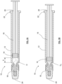
- the barrel 12 contains a particular dosage D of a liquid medicine, and the stopper 14 is arranged at the liquid level of the dosage D.
- the dosage D is small relative to the total capacity of the barrel 12, as shown by the empty space behind the stopper 14.
- An even smaller dosage D 0 in the same barrel 12 is shown in FIG. 1B .
- a distance X between the stopper 14 and the tip 18 decreases.
- the drugs also become more difficult to dispense in a smooth manner.
- a different size of barrel 12 can be used to accommodate small dosages D 0 and maintain a certain distance X between the stopper 14 and the tip 18.
- using different barrel sizes increases the complexity of manufacturing, filling, and stoppering syringes.
- a given filling and stoppering machine may not be able to accommodate all possible barrel sizes.
- Such issues particularly arise for dosages in the microliter range, e.g., 10 to 100 ⁇ l, since the capacity of the most common syringes is 0.5ml or 1 ml. In some cases, capacity of the syringe ranges from 0.5 ml to 3 ml.
- Dosages of liquid medicines in this capacity are used, e.g., in ophthalmological treatments or in gene cell therapies.
- Example implementations of a standard syringe e.g. a 0.5 ml or 1 ml syringe
- a standard syringe e.g. a 0.5 ml or 1 ml syringe
- dosages in the microliter range are shown in FIG. 2 to 6 .
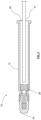
- a compressible spacer 28 inserted in the barrel 12 prior to filling.
- the spacer 28 can be inserted using an insertion rod or tube that is similar to the equipment used to insert a stopper 14.
- the spacer 28 is sized and shaped so that it can be inserted through the opening 20 of the barrel 12.
- the spacer 28 is made of an elastic or compressible material.
- the spacer 28 can include a porous material.
- "porous" means that the spacer 28 has many small holes.
- liquid medicine can pass through the holes in the spacer's porous material.
- a nozzle N of a syringe filling machine can enter the barrel 12 through the opening and fill the barrel 12 with a predetermined quantity or dosage D 0 of a liquid medicine (not shown).
- the liquid medicine can pass through the pores within spacer 28 and come to rest in the space between the spacer 28 and, e.g., the cap 24.
- the spacer's pores retain and absorb the liquid medicine, while the rest of the spacer displaces the liquid medicine.
- the spacer displaces the liquid medicine without absorbing it.
- the nozzle N can be part of an existing filling machine or system that is used to fill other types of syringes.
- Automated filling machines can be programmed to precisely fill a syringe with a pre-determined dosage of liquid medicine, which is more hygienic and accurate than, e.g., manually filling a syringe from a vial of liquid to a marking on the syringe barrel. The improvement in accuracy becomes more pronounced as the size of the dosage decreases. Additionally, automated filling machines can help to reduce drug-related waste can arise, e.g., when some of the drug remains in a vial after a syringe is manually filled.
- a spacer 28 is shown in a relaxed or uncompressed state that is also shown in FIG. 2 .
- the spacer 28 is not subjected to external forces and has a size or volume that can be expressed, e.g., in terms of diameter ⁇ and height H.
- “compressible” means that the size or volume of the spacer 28 can be reduced by applying pressure, e.g., from the stopper 14 and the walls of the barrel 12.
- the spacer 28 is shown having a cylindrical shape 29, it can also take the shape of a rectangular or hexagonal block, for example.
- the spacer 28 is schematically illustrated as having a continuous monolithic shape 29.
- the spacer 28 can consist of a single piece of material cut from a larger piece of material.
- the spacer 28 can also include multiple parts.
- the spacer 28 can include an elastic compressible material with a coated or laminated outer surface.
- the spacer 28 can include a porous material, meaning that it has a structure that includes a plurality of interconnected cells 30 or pores, as schematically shown in FIG. 4 . More specifically, each cell 30 has walls, but the walls of the cells are not completely closed. Such an open-cell structure allows the liquid medicine to pass through and fill the spacer, similarly to a sponge absorbing water.
- "absorb” means that the material of spacer 28 can temporarily retain the liquid medicine within its pores or cells, and the liquid medicine can be expelled from the pores or cell by applying pressure to the spacer 28, e.g., with the stopper 14 and the plunger 16.
- the material of the spacer is "insoluble,” meaning that it is incapable of being dissolved in in the liquid medicine.
- the material of the spacer can include a mixture of open and closed cells 30.
- the structure of the spacer 28 can also depend on the material used for the spacer 28.
- the spacer 28 can include a porous material that comprises a foam, in particular a metal, latex, rubber, polymer, or alginate foam.
- Polymer foams can include polyurethane, polystyrene, or polyolefin foams.
- the material of the spacer can be low-particle material that meets the standards of USP ⁇ 789> and/or meet the biocompatibility standards of ISO 10993.
- Other criteria for selecting the spacer's material can include compatibility with the liquid medicine, shelf stability, toxicity, extractables and leachables, material elasticity, or material compressibility.
- Each material can have a particular density or porosity.
- the choice of such properties can be adjusted to the dosage D 0 of liquid medicine.
- material of the spacer can be chosen so that the total volume of the pores or cells 30 is based on the dosage D 0 , e.g., 20, 25, 30, 40, 50, or 100 ⁇ l.
- a stopper 14 is inserted to form a pre-filled syringe, as illustrated in FIG. 4A . Due to the size of the spacer 28, a sufficient distance X between the stopper 14 and the barrel tip 18 is maintained despite the small volume of dosage D 0 .
- the same filling and stoppering machine that is used for syringes without a spacer can also be used for the syringe 10 in FIG. 4 .
- a first end of the spacer 28 rests against an annular inner shoulder 32 of the barrel 12 that is adjacent to the tip 18.
- a second end of the spacer 28 abuts an end face 34 of the stopper 14.
- the height H of the spacer 28 substantially corresponds to the distance X between the stopper 14 and the tip 18.
- the height H of the spacer 28 can be chosen to provide a certain distance X or stroke length of the stopper 14 and piston 16 as the liquid is dispensed.
- the diameter ⁇ of the spacer 28 may substantially correspond to the inner diameter of the syringe barrel 12.
- “substantially correspond” can include a gap between the spacer 28 and the inner surface of the barrel 12 that makes it easier to insert the spacer 28 during assembly.
- the syringe 10 and spacer 28 shown in FIG. 4B are similar to the ones shown in FIG. 4A .
- the spacer 28 includes a projection or protrusion 36 that extends past the inner shoulder 32 and toward the tip 18 of the barrel 12.
- the projection 36 is described in more detail below in reference to FIG. 6 .
- the cap 24 is replaced by a hollow needle 26 that is attached to the barrel tip 18 for injecting the liquid medicine.
- the drug is injected by moving the plunger 16 and stopper 14 towards the barrel tip 18. This movement compresses the spacer 28 and reduces its size relative to what is shown in FIG. 2 to 4 . When a certain level of compression is reached, the spacer 28 prevents the stopper 14 from moving any further towards the barrel tip 18.
- the deformation characteristics of the spacer 28 can provide haptic feedback to the user that the intended dosage D 0 has been discharged from the syringe.
- the described syringe 10 may reduce the risk of overdosing that can occur when multiple amounts of the intended microliter dosage are filled in a syringe, and the user must manually control the amount of liquid that is injected into the patient. Such overfilling also leads to increased cost and waste of the pharmacological product.
- the density of the spacer material can be used to estimate an appropriately sized spacer for a particular dosage. Tests, measurements, and pre-clinical trials can be conducted to determine the specific dimensions to ensure an exact dosage of liquid.
- the spacer's material can be selected to provide a particular mechanical response or deformation.
- a material can be selected so that pushing the plunger 16 and the stopper 14 causes plastic deformation of the spacer 28.
- plastic deformation refers to a permanent deformation or change in the spacer's shape, i.e., the spacer 28 does not fully or partially return to its initial size and shape.
- the spacer may elastically deform, i.e., regain at least part of its initial shape after compression. In such cases, a delay between the compression and re-expansion can prevent the stopper 14 from moving away from the tip 18 and creating a vacuum in the barrel 12 after injection has been completed.
- FIG. 6 illustrates compressed views of the spacers in FIG. 4A and 4B .
- an upper view (I) corresponds to an enlarged version of FIG. 5 , showing the spacer 28 of FIG. 4A in the compressed state.
- the end surface may slightly bulge towards the tip 18 without extending past the inner shoulder 32.
- a neck portion 38 between the inner shoulder 32 and the tip 18 of the barrel 12 may still hold a residual volume R of the liquid.
- the lower view (II) shows the spacer 28 of FIG. 4B , which includes the protrusion 36.
- the protrusion 36 extends into the neck portion 38 of the barrel 12 and can reduce the residual volume R of liquid that remains in the neck portion 38. Such a reduction may be advantageous for small doses (e.g. microliters) of costly medications.
- the protrusion 36 is shown as having a tapered or conical shapes. However, other shapes that are adapted to the neck portion 38 of the barrel 12 can also be used. Furthermore, although the protrusion 36 is shown in conjunction with a cylindrical spacer 28, spacers having other shapes may also include a protrusion 36.
- the spacer 28 occupies a predetermined portion of the syringe barrel 12 to more comfortably accommodate small dosages of liquid medicines.
- the spacer 28 also increases the stroke length of the stopper 14 and plunger 16 (distance X) for injecting the small dosage of liquid medicines, making it possible to gently inject smaller dosages into the patient.
- dosages of liquid medicines in the range of microliters are injected into the human eye in the treatment of macular degeneration.
- the spacer described above also resists the movement of the stopper 14 towards the tip 18.
- a low-viscosity liquid may require a slow injection speed.
- One way to slow the injection speed is to increase friction between the outer surface of the stopper 14 and the inner surface of the barrel 12, i.e., increase the glide force.
- the spacer 28 can also be used to augment increased friction between the stopper and the barrel or to counteract low friction between the stopper and barrel.
- This effect of the spacer 28 is not limited to dosages of liquid in the microliter range.
- the material of the spacer 28 can be selected based on the compression characteristics to provide a "braking effect" that slows injection.
- One material property that can influence resistance or this braking effect is the stiffness of the material.
- the spacer 28 may include an elastic compressible materials with closed pores that do not absorb or retain the liquid.
- spacers according to the present invention displace but do not absorb the liquid inside of the barrel.
- the spacer 28 can also be laminated or include some kind of coating to prevent absorption of the liquid. In such implementations, the likelihood of liquid remaining in the spacer after injection is reduced.
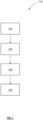
- a method 100 of filling a syringe 10 comprises: arranging 110 a syringe barrel in a holder with an open end of the syringe barrel pointing upwards; inserting 120 a compressible spacer configured to absorb a liquid into the syringe barrel through the open end; filling 130 the syringe barrel with the liquid through the open end; and inserting 140 a stopper into the syringe barrel through the open end.
- the liquid comprises a liquid pharmaceutical composition, such as vascular endothelial growth factor (VEGF) inhibitors that inhibit the activity of VEGF.
- VEGF vascular endothelial growth factor
- VEGF stimulate blood vessel formation.
- VEGF-A plays a role in wet form age-related macular degeneration.
- VEGF inhibitors can be administered in the form of intravitreal injections.
- the syringe barrel is sized for a 0.5 ml, a 1.0 ml, a 1.5 ml, 2.0 ml, 2.5 ml, or a 3.0 ml syringe, and filling 130 the syringe barrel with a liquid comprises filling 10 ⁇ l to 100 ⁇ l, more specifically 10 ⁇ l to 50 ⁇ l, and in particular, 10 ⁇ l, 20 ⁇ l, 30 ⁇ l, 40 ⁇ l, or 50 ⁇ l, of the liquid into the syringe barrel.
- the method 100 can use standard syringe sizes to accurately administer microliter dosages of liquids in an ergonomic manner, as described above.
- the present disclosure includes all combinations of syringe barrel sizes and dosages of liquids described above, e.g. a barrel sized for a 1.5 ml syringe and 50 ⁇ l of the liquid.
- the disclosure also includes ranges between the specific points within the list, e.g. a barrel size ranging from 1.0 to 2.0 ml combined with a dosage ranging from 20 to 50 ⁇ l.
- inserting 120 the spacer into the syringe barrel through the open end comprises the use of vent tube stoppering, in other words, the tube used to insert the stopper 14 into the syringe 10.
- using a positioning tube can include arranging a positioning tube with one end inside of the syringe barrel 12; inserting the spacer into an opposite end of the positioning tube; and pushing, using a plunger, the spacer through the positioning tube and into the syringe barrel.
- the method 100 can be implemented to fill a single syringe 10, it can also be used to fill a tray or nest that contains multiple identical syringes.
- the syringe barrel 12 is one of a plurality of syringe barrels arranged in a tray, with the open end of each syringe barrel pointing upwards. Trays of syringe barrels 12 can be sealed after manufacturing to maintain hygiene and safety standards. In such cases, inserting 120 the spacer into each syringe barrel can happen before or after the sealing and packaging step. When it takes place before the sealing step, the tray can be moved at a later time to, e.g., a filling and vent tube stoppering station for filling the syringe barrels and inserting the stoppers.
- a filling and vent tube stoppering station for filling the syringe barrels and inserting the stoppers.
- one part of the machine can fill one syringe barrel with the liquid while another part of the machine simultaneously inserts a stopper into a barrel that has already been filled.
- This type of parallel processing may reduce the overall manufacturing time for filling the syringe.
- pre-filled syringes have been described for pre-filled syringes.
- pre-filled syringes are limited to a small number of formats or volumes, and the machines and equipment for filling pre-filled syringes are based on the size and volume of the syringe.
- the implementations of the present disclosure can adapt existing syringes to very small injection volumes, as described above.
- the implementations are not limited to pre-filled syringes and can also be applied to disposable, single-use syringes. For example, single-use syringes are manually filled from a shelf-stable vial of liquid.
Landscapes
- Health & Medical Sciences (AREA)
- Vascular Medicine (AREA)
- Engineering & Computer Science (AREA)
- Anesthesiology (AREA)
- Biomedical Technology (AREA)
- Heart & Thoracic Surgery (AREA)
- Hematology (AREA)
- Life Sciences & Earth Sciences (AREA)
- Animal Behavior & Ethology (AREA)
- General Health & Medical Sciences (AREA)
- Public Health (AREA)
- Veterinary Medicine (AREA)
- Infusion, Injection, And Reservoir Apparatuses (AREA)
Description
- This disclosure relates to syringes for administering liquids into the body.
- Generally, syringes are used to inject liquids (e.g. liquid medicines or saline solution) into the body or to extract blood from the body. Syringes include a barrel, a gasket or stopper that forms an air-tight and liquid-tight seal with the barrel, and a piston or plunger that translates the stopper. The barrel includes a tip that is fitted with a hollow hypodermic needle. Syringe barrels can be made of various materials, such as metal, glass, or polymers (plastics).
- Some syringes are pre-filled with a single dose of medication. Pre-filled syringes are used to both package and deliver the medication and face certain requirements. For example, the material of the syringe barrel must be free from impurities, so-called extractables and leachables, that affect the stability or efficacy of the medication stored in the barrel. The material of the barrel should also prevent oxygen permeation and form a tight seal with the gasket during storage. High-performance plastics, such as cyclic olefin polymers (COP), can be used to manufacture the barrel of a pre-filled syringe.
- Other syringes are manually filled, e.g., from a vial containing a liquid medicine.
- Syringes face strict safety and manufacturing requirements, for example, with respect to the materials used for the syringe components. The specific medication administered using a syringe can introduce further requirements, for example, the speed at which the stopper and plunger are moved in order to dispense the medication.
-
US 2014/350483 A1 discloses a syringe containing a compressible porous matrix, which compressible porous matrix has in it a pharmaceutical in a soluble glass, methods of producing and using the syringe, and compressible porous matrix inserts for insertion into a syringe barrel. - The present invention provides a syringe, a syringe barrel and a method of filling a syringe that can accurately and safely administer liquid. In particular,
claim 1 provides such a syringe barrel, claim 5 provides such a syringe, and claim 7 provides a such a method of filling a syringe. Further advantageous embodiments of the present invention are set out in the dependent claims. - According to the present invnention, a syringe barrel includes a hollow body with an opening configured to receive a stopper, a tip configured for connection to a hollow needle, and a compressible spacer arranged inside the hollow body and adjacent to the tip, wherein the spacer comprises an insoluble material configured to displace a liquid filled in the hollow body.
- There is a gap between the compressible spacer and the inner surface of the barrel. The compressible spacer is configured to displace but not to absorb or retain the liquid inside of the barrel.
- According to the present disclosure, the spacer includes a porous material configured to absorb the liquid.
- According to the present disclosure, the porous material includes a foam, in particular a metal, latex, rubber, polymer, or alginate foam.
- According to the present disclosure, the porous material includes a polyurethane, polystyrene, or polyolefin foam.
- Preferably, the syringe barrel includes a neck portion arranged between the hollow body and the tip. The spacer includes a protrusion, and the neck portion is configured to receive the protrusion.
- Preferably, the hollow body is sized for a 0.5 ml, a 1.0 ml, or a 1.5 ml syringe, and the spacer is configured to displace 10 to 100 µl, in particular 10 to 50 µl of a liquid.
- Preferably, the spacer consists of a single piece of material.
- According to the present invention, a syringe including a syringe barrel according to any of the embodiments above and a stopper received in the body of the syringe barrel is provided. The spacer is arranged between the barrel tip and the stopper.
- Preferably, the hollow body includes an annular inner shoulder, wherein the spacer rests against the annular inner shoulder, and an end face of the stopper abuts the spacer.
- According to the present invention, a method of filling a syringe includes: arranging a syringe barrel in a holder with an open end of the syringe barrel pointing upwards; inserting a compressible spacer that includes an insoluble material configured to displace a liquid into the syringe barrel through the open end; filling the syringe barrel with the liquid, in particular a liquid pharmaceutical composition, through the open end; and inserting a stopper into the syringe barrel through the open end. There is a gap between the compressible spacer and the inner surface of the barrel. The compressible spacer is configured to displace but not to absorb or retain the liquid inside of the barrel.
- According to the present disclosure, the spacer includes a porous material configured to absorb the liquid.
- Preferably, the liquid pharmaceutical composition includes vascular endothelial growth factor (VEGF) inhibitors.
- Preferably, the syringe barrel is sized for a 0.5 ml, a 1.0 ml, or a 1.5 ml syringe, and filling the syringe barrel with a liquid includes filling 10 µl to 100 µl of the liquid into the syringe barrel.
- Preferably, inserting the spacer into the syringe barrel through the open end includes: arranging a tube with one end inside of the syringe barrel; inserting the spacer into an opposite end of the tube; and pushing, using a plunger, the spacer through the tube and into the syringe barrel.
- Preferably, the syringe barrel is one of a plurality of syringe barrels arranged in a tray, with the open end of each syringe barrel pointing upwards, and a compressible spacer is inserted into each syringe barrel in the tray. The implementation further includes sealing the tray for storage before filling each syringe barrel with the liquid.
- Preferably, the method includes using a filling and vent tube stoppering machine to fill multiple syringe barrels with the liquid and insert stoppers into multiple syringe barrels in parallel.
- The details of one or more implementations of the subject matter of this specification are set forth in the accompanying drawings and the subsequent description. Other features, aspects, and advantages of the subject matter will become apparent from the description, the drawings, and the claims.
-
-
FIG. 1 is a schematic cross-sectional view of a pre-filled syringe. -
FIG. 2 is a schematic cross-sectional view of a syringe and a compressible spacer according to an implementation. -
FIG. 3 is an enlarged schematic representation of a compressible spacer according to an implementation. -
FIG. 4 is a schematic cross-sectional view of a pre-filled syringe according to an implementation. -
FIG. 5 is a schematic cross-sectional view of the syringe ofFIG. 4 attached to a hypodermic needle. -
FIG. 6 is an enlarged, partial cross-section of a syringe according to two implementations. -
FIG. 7 is a flowchart for filling a syringe according to an implementation - Like reference numbers represent corresponding parts throughout the disclosure.
- This disclosure relates to syringes for injecting liquids in the body. Injected liquids can serve a therapeutic purpose and include pharmaceutical compositions in some cases. Other examples of injected liquids are saline solution. The following description is not limited with respect to the injected liquid and therefore uses the generic term "liquid."
- Referring to
FIG. 1A , asyringe 10 is used to introduce liquids, into skin or tissue and includes abarrel 12, a gasket or stopper 14 that seals thebarrel 12, and a piston orplunger 16 that is connected to thestopper 14. Thebarrel 12 is a continuous structure that extends from atip 18 to an opening 20. Aflange 22 can be provided adjacent to the opening.. In the illustrated embodiment, thetip 18 of thebarrel 12 is covered by acap 24, e.g., a Luer lock-style connector. Prior to use, thecap 24 can be replaced by a hollow needle 26 (FIG. 5 ). In some embodiments, a needle is integrally molded with thetip 18. The liquid is dispensed by holding theflange 22 and depressing theplunger 16. Theplunger 16 can be stored separately from thestopper 14 and connected prior to use. - Generally speaking, syringe barrels are molded, coated, and assembled with a cap in automated systems. Several empty barrels are loaded, tip first, into a tray or nest with the open end of the barrel exposed. Such trays can be loaded into filling and stoppering machines that inject the liquid substance into the barrel and insert the stopper through the opening of the barrel to manufacture a pre-filled syringe. When the stopper is inserted into the barrel, it is aligned with the level of the liquid. Depending on the amount or dose of substance, the stopper will have a different position along the length of the barrel.
- Referring again to
FIG. 1A , thebarrel 12 contains a particular dosage D of a liquid medicine, and thestopper 14 is arranged at the liquid level of the dosage D. The dosage D is small relative to the total capacity of thebarrel 12, as shown by the empty space behind thestopper 14. An even smaller dosage D0 in thesame barrel 12 is shown inFIG. 1B . As the dosage D becomes progressively smaller, a distance X between thestopper 14 and thetip 18 decreases. As the distance X decreases, it becomes difficult to tell whether thesyringe 10 is filled, especially for colorless liquid medicines. The drugs also become more difficult to dispense in a smooth manner. - In some cases, a different size of
barrel 12 can be used to accommodate small dosages D0 and maintain a certain distance X between thestopper 14 and thetip 18. However, using different barrel sizes increases the complexity of manufacturing, filling, and stoppering syringes. For example, a given filling and stoppering machine may not be able to accommodate all possible barrel sizes. Such issues particularly arise for dosages in the microliter range, e.g., 10 to 100 µl, since the capacity of the most common syringes is 0.5ml or 1 ml. In some cases, capacity of the syringe ranges from 0.5 ml to 3 ml. Dosages of liquid medicines in this capacity are used, e.g., in ophthalmological treatments or in gene cell therapies. Example implementations of a standard syringe (e.g. a 0.5 ml or 1 ml syringe) that is adapted to dosages in the microliter range are shown inFIG. 2 to 6 . - In
FIG. 2 , acompressible spacer 28 inserted in thebarrel 12 prior to filling. For example, thespacer 28 can be inserted using an insertion rod or tube that is similar to the equipment used to insert astopper 14. Thespacer 28 is sized and shaped so that it can be inserted through theopening 20 of thebarrel 12. As explained below in more detail, thespacer 28 is made of an elastic or compressible material. In some cases, thespacer 28 can include a porous material. In this disclosure, "porous" means that thespacer 28 has many small holes. In some implementations, liquid medicine can pass through the holes in the spacer's porous material. - For example, a nozzle N of a syringe filling machine can enter the
barrel 12 through the opening and fill thebarrel 12 with a predetermined quantity or dosage D0 of a liquid medicine (not shown). The liquid medicine can pass through the pores withinspacer 28 and come to rest in the space between thespacer 28 and, e.g., thecap 24. In such cases according to the present disclosure, the spacer's pores retain and absorb the liquid medicine, while the rest of the spacer displaces the liquid medicine. As described below, according to the present invention, the spacer displaces the liquid medicine without absorbing it. - The nozzle N can be part of an existing filling machine or system that is used to fill other types of syringes. Automated filling machines can be programmed to precisely fill a syringe with a pre-determined dosage of liquid medicine, which is more hygienic and accurate than, e.g., manually filling a syringe from a vial of liquid to a marking on the syringe barrel. The improvement in accuracy becomes more pronounced as the size of the dosage decreases. Additionally, automated filling machines can help to reduce drug-related waste can arise, e.g., when some of the drug remains in a vial after a syringe is manually filled.
- In
FIG. 3 , aspacer 28 is shown in a relaxed or uncompressed state that is also shown inFIG. 2 . In this state, thespacer 28 is not subjected to external forces and has a size or volume that can be expressed, e.g., in terms of diameter Ø and height H. In this disclosure, "compressible" means that the size or volume of thespacer 28 can be reduced by applying pressure, e.g., from thestopper 14 and the walls of thebarrel 12. Although thespacer 28 is shown having acylindrical shape 29, it can also take the shape of a rectangular or hexagonal block, for example. InFIG. 3 , thespacer 28 is schematically illustrated as having a continuousmonolithic shape 29. For example, thespacer 28 can consist of a single piece of material cut from a larger piece of material. However, thespacer 28 can also include multiple parts. For example, thespacer 28 can include an elastic compressible material with a coated or laminated outer surface. - The
spacer 28 can include a porous material, meaning that it has a structure that includes a plurality ofinterconnected cells 30 or pores, as schematically shown inFIG. 4 . More specifically, eachcell 30 has walls, but the walls of the cells are not completely closed. Such an open-cell structure allows the liquid medicine to pass through and fill the spacer, similarly to a sponge absorbing water. In this disclosure, "absorb" means that the material ofspacer 28 can temporarily retain the liquid medicine within its pores or cells, and the liquid medicine can be expelled from the pores or cell by applying pressure to thespacer 28, e.g., with thestopper 14 and theplunger 16. Furthermore, the material of the spacer is "insoluble," meaning that it is incapable of being dissolved in in the liquid medicine. - Although all of the
cells 30 inFIG. 3 are shown having open walls, the material of the spacer can include a mixture of open andclosed cells 30. The structure of thespacer 28 can also depend on the material used for thespacer 28. For example, thespacer 28 can include a porous material that comprises a foam, in particular a metal, latex, rubber, polymer, or alginate foam. Polymer foams can include polyurethane, polystyrene, or polyolefin foams. In some implementations, the material of the spacer can be low-particle material that meets the standards of USP <789> and/or meet the biocompatibility standards of ISO 10993. Other criteria for selecting the spacer's material can include compatibility with the liquid medicine, shelf stability, toxicity, extractables and leachables, material elasticity, or material compressibility. - Each material can have a particular density or porosity. The choice of such properties can be adjusted to the dosage D0 of liquid medicine. For example, material of the spacer can be chosen so that the total volume of the pores or
cells 30 is based on the dosage D0, e.g., 20, 25, 30, 40, 50, or 100 µl. Once part of the dosage D0 has been absorbed by thespacer 28, astopper 14 is inserted to form a pre-filled syringe, as illustrated inFIG. 4A . Due to the size of thespacer 28, a sufficient distance X between thestopper 14 and thebarrel tip 18 is maintained despite the small volume of dosage D0. For example, the same filling and stoppering machine that is used for syringes without a spacer can also be used for thesyringe 10 inFIG. 4 . - In
FIG. 4A , a first end of thespacer 28 rests against an annularinner shoulder 32 of thebarrel 12 that is adjacent to thetip 18. A second end of thespacer 28 abuts anend face 34 of thestopper 14. In this case, the height H of thespacer 28 substantially corresponds to the distance X between thestopper 14 and thetip 18. In some cases, the height H of thespacer 28 can be chosen to provide a certain distance X or stroke length of thestopper 14 andpiston 16 as the liquid is dispensed. Additionally or alternatively, the diameter Ø of thespacer 28 may substantially correspond to the inner diameter of thesyringe barrel 12. In this context, "substantially correspond" can include a gap between thespacer 28 and the inner surface of thebarrel 12 that makes it easier to insert thespacer 28 during assembly. - The
syringe 10 andspacer 28 shown inFIG. 4B are similar to the ones shown inFIG. 4A . However, thespacer 28 includes a projection orprotrusion 36 that extends past theinner shoulder 32 and toward thetip 18 of thebarrel 12. Theprojection 36 is described in more detail below in reference toFIG. 6 . - In
FIG. 5 , thecap 24 is replaced by ahollow needle 26 that is attached to thebarrel tip 18 for injecting the liquid medicine. The drug is injected by moving theplunger 16 andstopper 14 towards thebarrel tip 18. This movement compresses thespacer 28 and reduces its size relative to what is shown inFIG. 2 to 4 . When a certain level of compression is reached, thespacer 28 prevents thestopper 14 from moving any further towards thebarrel tip 18. The deformation characteristics of thespacer 28 can provide haptic feedback to the user that the intended dosage D0 has been discharged from the syringe. Overall, the describedsyringe 10 may reduce the risk of overdosing that can occur when multiple amounts of the intended microliter dosage are filled in a syringe, and the user must manually control the amount of liquid that is injected into the patient. Such overfilling also leads to increased cost and waste of the pharmacological product. In some cases, the density of the spacer material can be used to estimate an appropriately sized spacer for a particular dosage. Tests, measurements, and pre-clinical trials can be conducted to determine the specific dimensions to ensure an exact dosage of liquid. - In some cases, the spacer's material can be selected to provide a particular mechanical response or deformation. For example, a material can be selected so that pushing the
plunger 16 and thestopper 14 causes plastic deformation of thespacer 28. In this disclosure, "plastic deformation" refers to a permanent deformation or change in the spacer's shape, i.e., thespacer 28 does not fully or partially return to its initial size and shape. Alternatively, the spacer may elastically deform, i.e., regain at least part of its initial shape after compression. In such cases, a delay between the compression and re-expansion can prevent thestopper 14 from moving away from thetip 18 and creating a vacuum in thebarrel 12 after injection has been completed. -
FIG. 6 illustrates compressed views of the spacers inFIG. 4A and 4B . More specifically, an upper view (I) corresponds to an enlarged version ofFIG. 5 , showing thespacer 28 ofFIG. 4A in the compressed state. As thestopper 14 presses thespacer 28 against the annularinner shoulder 32 of the barrel, the end surface may slightly bulge towards thetip 18 without extending past theinner shoulder 32. In such cases, aneck portion 38 between theinner shoulder 32 and thetip 18 of thebarrel 12 may still hold a residual volume R of the liquid. In contrast to this, the lower view (II) shows thespacer 28 ofFIG. 4B , which includes theprotrusion 36. At the time of compression, theprotrusion 36 extends into theneck portion 38 of thebarrel 12 and can reduce the residual volume R of liquid that remains in theneck portion 38. Such a reduction may be advantageous for small doses (e.g. microliters) of costly medications. InFIG. 4B and6 , theprotrusion 36 is shown as having a tapered or conical shapes. However, other shapes that are adapted to theneck portion 38 of thebarrel 12 can also be used. Furthermore, although theprotrusion 36 is shown in conjunction with acylindrical spacer 28, spacers having other shapes may also include aprotrusion 36. - As described in
FIG. 2 to 6 , thespacer 28 occupies a predetermined portion of thesyringe barrel 12 to more comfortably accommodate small dosages of liquid medicines. Thespacer 28 also increases the stroke length of thestopper 14 and plunger 16 (distance X) for injecting the small dosage of liquid medicines, making it possible to gently inject smaller dosages into the patient. For example, dosages of liquid medicines in the range of microliters are injected into the human eye in the treatment of macular degeneration. - In addition to adapting the inner volume of a standard syringe, the spacer described above also resists the movement of the
stopper 14 towards thetip 18. In some cases, a low-viscosity liquid may require a slow injection speed. One way to slow the injection speed is to increase friction between the outer surface of thestopper 14 and the inner surface of thebarrel 12, i.e., increase the glide force. However, thespacer 28 can also be used to augment increased friction between the stopper and the barrel or to counteract low friction between the stopper and barrel. - This effect of the
spacer 28 is not limited to dosages of liquid in the microliter range. For example, the material of thespacer 28 can be selected based on the compression characteristics to provide a "braking effect" that slows injection. One material property that can influence resistance or this braking effect is the stiffness of the material. In such cases according to the present invention, thespacer 28 may include an elastic compressible materials with closed pores that do not absorb or retain the liquid. In other words, spacers according to the present invention displace but do not absorb the liquid inside of the barrel. Thespacer 28 can also be laminated or include some kind of coating to prevent absorption of the liquid. In such implementations, the likelihood of liquid remaining in the spacer after injection is reduced. - Referring to
FIG. 7 , amethod 100 of filling asyringe 10 is schematically shown. Themethod 100 comprises: arranging 110 a syringe barrel in a holder with an open end of the syringe barrel pointing upwards; inserting 120 a compressible spacer configured to absorb a liquid into the syringe barrel through the open end; filling 130 the syringe barrel with the liquid through the open end; and inserting 140 a stopper into the syringe barrel through the open end. - In some implementations of the
method 100, the liquid comprises a liquid pharmaceutical composition, such as vascular endothelial growth factor (VEGF) inhibitors that inhibit the activity of VEGF. VEGF stimulate blood vessel formation. VEGF-A plays a role in wet form age-related macular degeneration. VEGF inhibitors can be administered in the form of intravitreal injections. - In some implementations of the
method 100, the syringe barrel is sized for a 0.5 ml, a 1.0 ml, a 1.5 ml, 2.0 ml, 2.5 ml, or a 3.0 ml syringe, and filling 130 the syringe barrel with a liquid comprises filling 10 µl to 100 µl, more specifically 10 µl to 50 µl, and in particular, 10 µl, 20 µl, 30 µl, 40 µl, or 50 µl, of the liquid into the syringe barrel. In this way, themethod 100 can use standard syringe sizes to accurately administer microliter dosages of liquids in an ergonomic manner, as described above. The present disclosure includes all combinations of syringe barrel sizes and dosages of liquids described above, e.g. a barrel sized for a 1.5 ml syringe and 50 µl of the liquid. The disclosure also includes ranges between the specific points within the list, e.g. a barrel size ranging from 1.0 to 2.0 ml combined with a dosage ranging from 20 to 50 µl. - In some implementations of the
method 100, inserting 120 the spacer into the syringe barrel through the open end comprises the use of vent tube stoppering, in other words, the tube used to insert thestopper 14 into thesyringe 10. For example, using a positioning tube can include arranging a positioning tube with one end inside of thesyringe barrel 12; inserting the spacer into an opposite end of the positioning tube; and pushing, using a plunger, the spacer through the positioning tube and into the syringe barrel. - Although the
method 100 can be implemented to fill asingle syringe 10, it can also be used to fill a tray or nest that contains multiple identical syringes. In such implementations, thesyringe barrel 12 is one of a plurality of syringe barrels arranged in a tray, with the open end of each syringe barrel pointing upwards. Trays of syringe barrels 12 can be sealed after manufacturing to maintain hygiene and safety standards. In such cases, inserting 120 the spacer into each syringe barrel can happen before or after the sealing and packaging step. When it takes place before the sealing step, the tray can be moved at a later time to, e.g., a filling and vent tube stoppering station for filling the syringe barrels and inserting the stoppers. - In implementations that include the use of a filling and vent tube stoppering machine, one part of the machine can fill one syringe barrel with the liquid while another part of the machine simultaneously inserts a stopper into a barrel that has already been filled. This type of parallel processing may reduce the overall manufacturing time for filling the syringe. In such implementations, it is also possible for a third part of the machine to simultaneously insert a compressible spacer in yet further syringe barrel.
- The implementations above have been described for pre-filled syringes. Generally speaking, pre-filled syringes are limited to a small number of formats or volumes, and the machines and equipment for filling pre-filled syringes are based on the size and volume of the syringe. Under these circumstances, the implementations of the present disclosure can adapt existing syringes to very small injection volumes, as described above. However, the implementations are not limited to pre-filled syringes and can also be applied to disposable, single-use syringes. For example, single-use syringes are manually filled from a shelf-stable vial of liquid.
- While this specification contains many specific details of implementations, these should not be construed as limitations on the scope of any invention or of what may be claimed, but rather as descriptions of features that may be specific to particular implementations. Certain features that are described in this specification in the context of separate implementations can also be implemented in combination in a single implementation. Conversely, various features that are described in the context of a single implementation can also be implemented in multiple implementations separately or in combination with one another. Moreover, although features may be described herein as acting in certain combinations and even initially claimed as such, one or more features from a claimed combination can in some cases be excised from the combination, and the claimed combination may be directed to a sub-combination of features.
- Similarly, while operations are depicted in the drawings in a particular order, this should not be understood as requiring that such operations be performed in the particular order shown or in sequential order, or that all illustrated operations be performed, to achieve desirable results. In certain circumstances, multitasking and parallel processing may be advantageous. Moreover, the separation of various system modules and components in the implementations described herein should not be understood as requiring such separation in all implementations.
- Particular implementations of the subject matter have been described. Other implementations are within the scope of the following claims.
Claims (12)
- A syringe barrel (12) comprisinga hollow body with an opening (20) configured to receive a stopper (14),a tip (18) configured for connection to a hollow needle (26), anda compressible spacer (28) arranged inside the hollow body and adjacent to the tip (18), wherein the spacer (28) comprises an insoluble material configured to displace a liquid filled in the hollow body, characterized in thatthere is a gap between the compressible spacer (28) and the inner surface of the barrel (12), andthe compressible spacer (28) is configured to displace but not to absorb or retain the liquid inside of the barrel (12).
- The syringe barrel (12) of claim 1, further comprising a neck portion (38) arranged between the hollow body and the tip (18), wherein the spacer (28) comprises a protrusion (36), and wherein the neck portion (38) is configured to receive the protrusion (36).
- The syringe barrel (12) of claim 1 or 2, wherein the hollow body is sized for a 0.5 ml, a 1.0 ml, or a 1.5 ml syringe (10), and the spacer (28) is configured to displace 10 to 100 µl, in particular 10 to 50 µl of a liquid.
- The syringe barrel (12) of any of claims 1 to 3, wherein the spacer (28) consists of a single piece of material.
- A syringe (10) comprising a syringe barrel (12) according to any one of claims 1 to 3 and a stopper (14) received in the body of the syringe barrel (12), with the spacer (28) arranged between the barrel tip (18) and the stopper (14).
- The syringe (10) of claim 5, wherein the hollow body comprises an annular inner shoulder (32), wherein the spacer (28) rests against the annular inner shoulder (32), and an end face (34) of the stopper (14) abuts the spacer (28).
- A method (100) of filling a syringe (10), comprising:arranging (110) a syringe barrel (12) in a holder with an open end of the syringe barrel (12) pointing upwards;inserting (120) a compressible spacer (28) that comprises an insoluble material configured to displace a liquid into the syringe barrel (12) through the open end;filling (130) the syringe barrel (12) with the liquid, in particular a liquid pharmaceutical composition, through the open end; andinserting (140) a stopper (14) into the syringe barrel (12) through the open end, characterized in thatthere is a gap between the compressible spacer (28) and the inner surface of the barrel (12), andthe compressible spacer (28) is configured to displace but not to absorb or retain the liquid inside of the barrel (12).
- The method (100) of claim 7, wherein the liquid pharmaceutical composition comprises vascular endothelial growth factor (VEGF) inhibitors.
- The method (100) of claim 7 or 8, whereinthe syringe barrel (12) is sized for a 0.5 ml, a 1.0 ml, or a 1.5 ml syringe (10), andfilling (130) the syringe barrel (12) with a liquid comprises filling (130) 10 µl to 100 µl of the liquid into the syringe barrel (12).
- The method (100) of any of claims 7 to 9, wherein inserting (120) the spacer (28) into the syringe barrel (12) through the open end comprises:arranging a tube with one end inside of the syringe barrel (12);inserting the spacer (28) into an opposite end of the tube; andpushing, using a plunger, the spacer (28) through the tube and into the syringe barrel (12).
- The method (100) of any of claims 7 to 10,wherein the syringe barrel (12) is one of a plurality of syringe barrels (12) arranged in a tray, with the open end of each syringe barrel (12) pointing upwards,wherein a compressible spacer (28) is inserted into each syringe barrel (12) in the tray,further comprising sealing the tray for storage before filling (130) each syringe barrel (12) with the liquid.
- The method (100) of any one of claims 7 to 11, comprising
using a filling and vent tube stoppering machine to fill multiple syringe barrels (12) with the liquid and insert stoppers (14) into multiple syringe barrels (12) in parallel.
Priority Applications (1)
| Application Number | Priority Date | Filing Date | Title |
|---|---|---|---|
| EP20201811.5A EP3984574B1 (en) | 2020-10-14 | 2020-10-14 | Syringe with compressible spacer |
Applications Claiming Priority (1)
| Application Number | Priority Date | Filing Date | Title |
|---|---|---|---|
| EP20201811.5A EP3984574B1 (en) | 2020-10-14 | 2020-10-14 | Syringe with compressible spacer |
Publications (2)
| Publication Number | Publication Date |
|---|---|
| EP3984574A1 EP3984574A1 (en) | 2022-04-20 |
| EP3984574B1 true EP3984574B1 (en) | 2025-04-23 |
Family
ID=72885437
Family Applications (1)
| Application Number | Title | Priority Date | Filing Date |
|---|---|---|---|
| EP20201811.5A Active EP3984574B1 (en) | 2020-10-14 | 2020-10-14 | Syringe with compressible spacer |
Country Status (1)
| Country | Link |
|---|---|
| EP (1) | EP3984574B1 (en) |
Families Citing this family (1)
| Publication number | Priority date | Publication date | Assignee | Title |
|---|---|---|---|---|
| GB2630558A (en) * | 2023-03-31 | 2024-12-04 | Consort Medical Ltd | Improvements relating to the filling and stoppering of containers |
Family Cites Families (3)
| Publication number | Priority date | Publication date | Assignee | Title |
|---|---|---|---|---|
| US8268634B2 (en) * | 2007-11-29 | 2012-09-18 | Ameditech, Inc. | Fluid sample collecting and analyzing apparatus and method |
| GB2498774A (en) * | 2012-01-27 | 2013-07-31 | Bruce Roser | Glass-stabilised biological materials and syringe |
| US20160095604A1 (en) * | 2014-10-01 | 2016-04-07 | Daniel Gelbart | Mixing Syringe |
-
2020
- 2020-10-14 EP EP20201811.5A patent/EP3984574B1/en active Active
Also Published As
| Publication number | Publication date |
|---|---|
| EP3984574A1 (en) | 2022-04-20 |
Similar Documents
| Publication | Publication Date | Title |
|---|---|---|
| US11724038B2 (en) | Syringe assembly with inverse delivery | |
| JP7389162B2 (en) | Vial transfer and injection equipment and methods | |
| EP1703931B1 (en) | Positive displacement flush syringe | |
| US9717857B2 (en) | Medical injection device | |
| US9700682B2 (en) | Device for retaining and storing liquid media and method of expelling the liquid media | |
| JP2023052394A (en) | Devices and methods for overfilling drug containers | |
| US20090247955A1 (en) | Microliter injector | |
| US20150238702A1 (en) | Buffering Agent Delivery System for Anesthetic System | |
| US9375385B2 (en) | Pre-filled active vial having integral plunger assembly | |
| EP3984574A1 (en) | Syringe with compressible spacer | |
| US6685693B1 (en) | Method of preparing a syringe for injection | |
| JP2023021444A (en) | Syringe plunger stopper for high dose accuracy drug delivery | |
| EP3377148B1 (en) | Autoinjector | |
| CN116583255A (en) | Methods and devices for improving the efficiency of injectable drug delivery | |
| EP4617179A1 (en) | Stoppering tool system and method with improved stopper centering for installation in a syringe barrel | |
| US20240131262A1 (en) | Barrier Coated Sequential Stopper for a Multi-Chamber Syringe | |
| GB2418616A (en) | Injection device with a piston having needle and plunger attachments. | |
| WO2025064620A1 (en) | Stoppering tool system and method with distally loaded stopper for installtion in a syringe barrel | |
| EA045636B1 (en) | DEVICE AND METHOD FOR OVERFLOWING A CONTAINER WITH MEDICINE | |
| CN116437977A (en) | Fluid transfer system for drug delivery device | |
| EA052043B1 (en) | DEVICES AND METHODS FOR OVERFILLING CONTAINERS WITH MEDICINES |
Legal Events
| Date | Code | Title | Description |
|---|---|---|---|
| PUAI | Public reference made under article 153(3) epc to a published international application that has entered the european phase |
Free format text: ORIGINAL CODE: 0009012 |
|
| STAA | Information on the status of an ep patent application or granted ep patent |
Free format text: STATUS: REQUEST FOR EXAMINATION WAS MADE |
|
| 17P | Request for examination filed |
Effective date: 20201014 |
|
| AK | Designated contracting states |
Kind code of ref document: A1 Designated state(s): AL AT BE BG CH CY CZ DE DK EE ES FI FR GB GR HR HU IE IS IT LI LT LU LV MC MK MT NL NO PL PT RO RS SE SI SK SM TR |
|
| GRAP | Despatch of communication of intention to grant a patent |
Free format text: ORIGINAL CODE: EPIDOSNIGR1 |
|
| STAA | Information on the status of an ep patent application or granted ep patent |
Free format text: STATUS: GRANT OF PATENT IS INTENDED |
|
| RIC1 | Information provided on ipc code assigned before grant |
Ipc: A61M 5/31 20060101ALN20240618BHEP Ipc: A61M 5/315 20060101AFI20240618BHEP |
|
| INTG | Intention to grant announced |
Effective date: 20240704 |
|
| GRAJ | Information related to disapproval of communication of intention to grant by the applicant or resumption of examination proceedings by the epo deleted |
Free format text: ORIGINAL CODE: EPIDOSDIGR1 |
|
| STAA | Information on the status of an ep patent application or granted ep patent |
Free format text: STATUS: REQUEST FOR EXAMINATION WAS MADE |
|
| GRAP | Despatch of communication of intention to grant a patent |
Free format text: ORIGINAL CODE: EPIDOSNIGR1 |
|
| STAA | Information on the status of an ep patent application or granted ep patent |
Free format text: STATUS: GRANT OF PATENT IS INTENDED |
|
| INTC | Intention to grant announced (deleted) | ||
| RIC1 | Information provided on ipc code assigned before grant |
Ipc: A61M 5/31 20060101ALN20241113BHEP Ipc: A61M 5/315 20060101AFI20241113BHEP |
|
| INTG | Intention to grant announced |
Effective date: 20241128 |
|
| GRAS | Grant fee paid |
Free format text: ORIGINAL CODE: EPIDOSNIGR3 |
|
| GRAA | (expected) grant |
Free format text: ORIGINAL CODE: 0009210 |
|
| STAA | Information on the status of an ep patent application or granted ep patent |
Free format text: STATUS: THE PATENT HAS BEEN GRANTED |
|
| AK | Designated contracting states |
Kind code of ref document: B1 Designated state(s): AL AT BE BG CH CY CZ DE DK EE ES FI FR GB GR HR HU IE IS IT LI LT LU LV MC MK MT NL NO PL PT RO RS SE SI SK SM TR |
|
| REG | Reference to a national code |
Ref country code: GB Ref legal event code: FG4D |
|
| REG | Reference to a national code |
Ref country code: CH Ref legal event code: EP |
|
| REG | Reference to a national code |
Ref country code: DE Ref legal event code: R096 Ref document number: 602020049854 Country of ref document: DE |
|
| P01 | Opt-out of the competence of the unified patent court (upc) registered |
Free format text: CASE NUMBER: APP_18590/2025 Effective date: 20250416 |
|
| REG | Reference to a national code |
Ref country code: IE Ref legal event code: FG4D |
|
| REG | Reference to a national code |
Ref country code: NL Ref legal event code: MP Effective date: 20250423 |
|
| PG25 | Lapsed in a contracting state [announced via postgrant information from national office to epo] |
Ref country code: NL Free format text: LAPSE BECAUSE OF FAILURE TO SUBMIT A TRANSLATION OF THE DESCRIPTION OR TO PAY THE FEE WITHIN THE PRESCRIBED TIME-LIMIT Effective date: 20250423 |
|
| REG | Reference to a national code |
Ref country code: AT Ref legal event code: MK05 Ref document number: 1787196 Country of ref document: AT Kind code of ref document: T Effective date: 20250423 |
|
| PG25 | Lapsed in a contracting state [announced via postgrant information from national office to epo] |
Ref country code: PT Free format text: LAPSE BECAUSE OF FAILURE TO SUBMIT A TRANSLATION OF THE DESCRIPTION OR TO PAY THE FEE WITHIN THE PRESCRIBED TIME-LIMIT Effective date: 20250825 Ref country code: ES Free format text: LAPSE BECAUSE OF FAILURE TO SUBMIT A TRANSLATION OF THE DESCRIPTION OR TO PAY THE FEE WITHIN THE PRESCRIBED TIME-LIMIT Effective date: 20250423 Ref country code: FI Free format text: LAPSE BECAUSE OF FAILURE TO SUBMIT A TRANSLATION OF THE DESCRIPTION OR TO PAY THE FEE WITHIN THE PRESCRIBED TIME-LIMIT Effective date: 20250423 |
|
| REG | Reference to a national code |
Ref country code: LT Ref legal event code: MG9D |
|
| PG25 | Lapsed in a contracting state [announced via postgrant information from national office to epo] |
Ref country code: GR Free format text: LAPSE BECAUSE OF FAILURE TO SUBMIT A TRANSLATION OF THE DESCRIPTION OR TO PAY THE FEE WITHIN THE PRESCRIBED TIME-LIMIT Effective date: 20250724 Ref country code: NO Free format text: LAPSE BECAUSE OF FAILURE TO SUBMIT A TRANSLATION OF THE DESCRIPTION OR TO PAY THE FEE WITHIN THE PRESCRIBED TIME-LIMIT Effective date: 20250723 |
|
| PG25 | Lapsed in a contracting state [announced via postgrant information from national office to epo] |
Ref country code: PL Free format text: LAPSE BECAUSE OF FAILURE TO SUBMIT A TRANSLATION OF THE DESCRIPTION OR TO PAY THE FEE WITHIN THE PRESCRIBED TIME-LIMIT Effective date: 20250423 |
|
| PG25 | Lapsed in a contracting state [announced via postgrant information from national office to epo] |
Ref country code: BG Free format text: LAPSE BECAUSE OF FAILURE TO SUBMIT A TRANSLATION OF THE DESCRIPTION OR TO PAY THE FEE WITHIN THE PRESCRIBED TIME-LIMIT Effective date: 20250423 |
|
| PG25 | Lapsed in a contracting state [announced via postgrant information from national office to epo] |
Ref country code: HR Free format text: LAPSE BECAUSE OF FAILURE TO SUBMIT A TRANSLATION OF THE DESCRIPTION OR TO PAY THE FEE WITHIN THE PRESCRIBED TIME-LIMIT Effective date: 20250423 |
|
| PG25 | Lapsed in a contracting state [announced via postgrant information from national office to epo] |
Ref country code: AT Free format text: LAPSE BECAUSE OF FAILURE TO SUBMIT A TRANSLATION OF THE DESCRIPTION OR TO PAY THE FEE WITHIN THE PRESCRIBED TIME-LIMIT Effective date: 20250423 |
|
| PG25 | Lapsed in a contracting state [announced via postgrant information from national office to epo] |
Ref country code: RS Free format text: LAPSE BECAUSE OF FAILURE TO SUBMIT A TRANSLATION OF THE DESCRIPTION OR TO PAY THE FEE WITHIN THE PRESCRIBED TIME-LIMIT Effective date: 20250723 |
|
| PG25 | Lapsed in a contracting state [announced via postgrant information from national office to epo] |
Ref country code: IS Free format text: LAPSE BECAUSE OF FAILURE TO SUBMIT A TRANSLATION OF THE DESCRIPTION OR TO PAY THE FEE WITHIN THE PRESCRIBED TIME-LIMIT Effective date: 20250823 |
|
| PG25 | Lapsed in a contracting state [announced via postgrant information from national office to epo] |
Ref country code: LV Free format text: LAPSE BECAUSE OF FAILURE TO SUBMIT A TRANSLATION OF THE DESCRIPTION OR TO PAY THE FEE WITHIN THE PRESCRIBED TIME-LIMIT Effective date: 20250423 |
|
| PGFP | Annual fee paid to national office [announced via postgrant information from national office to epo] |
Ref country code: DE Payment date: 20251020 Year of fee payment: 6 |
|
| PGFP | Annual fee paid to national office [announced via postgrant information from national office to epo] |
Ref country code: GB Payment date: 20251024 Year of fee payment: 6 |
|
| PG25 | Lapsed in a contracting state [announced via postgrant information from national office to epo] |
Ref country code: SM Free format text: LAPSE BECAUSE OF FAILURE TO SUBMIT A TRANSLATION OF THE DESCRIPTION OR TO PAY THE FEE WITHIN THE PRESCRIBED TIME-LIMIT Effective date: 20250423 Ref country code: DK Free format text: LAPSE BECAUSE OF FAILURE TO SUBMIT A TRANSLATION OF THE DESCRIPTION OR TO PAY THE FEE WITHIN THE PRESCRIBED TIME-LIMIT Effective date: 20250423 |
|
| PGFP | Annual fee paid to national office [announced via postgrant information from national office to epo] |
Ref country code: FR Payment date: 20251027 Year of fee payment: 6 |
|
| PG25 | Lapsed in a contracting state [announced via postgrant information from national office to epo] |
Ref country code: CZ Free format text: LAPSE BECAUSE OF FAILURE TO SUBMIT A TRANSLATION OF THE DESCRIPTION OR TO PAY THE FEE WITHIN THE PRESCRIBED TIME-LIMIT Effective date: 20250423 |
|
| PG25 | Lapsed in a contracting state [announced via postgrant information from national office to epo] |
Ref country code: EE Free format text: LAPSE BECAUSE OF FAILURE TO SUBMIT A TRANSLATION OF THE DESCRIPTION OR TO PAY THE FEE WITHIN THE PRESCRIBED TIME-LIMIT Effective date: 20250423 |
|
| REG | Reference to a national code |
Ref country code: DE Ref legal event code: R097 Ref document number: 602020049854 Country of ref document: DE |
|
| PG25 | Lapsed in a contracting state [announced via postgrant information from national office to epo] |
Ref country code: RO Free format text: LAPSE BECAUSE OF FAILURE TO SUBMIT A TRANSLATION OF THE DESCRIPTION OR TO PAY THE FEE WITHIN THE PRESCRIBED TIME-LIMIT Effective date: 20250423 Ref country code: SK Free format text: LAPSE BECAUSE OF FAILURE TO SUBMIT A TRANSLATION OF THE DESCRIPTION OR TO PAY THE FEE WITHIN THE PRESCRIBED TIME-LIMIT Effective date: 20250423 |
|
| PG25 | Lapsed in a contracting state [announced via postgrant information from national office to epo] |
Ref country code: IT Free format text: LAPSE BECAUSE OF FAILURE TO SUBMIT A TRANSLATION OF THE DESCRIPTION OR TO PAY THE FEE WITHIN THE PRESCRIBED TIME-LIMIT Effective date: 20250423 |
|
| PLBE | No opposition filed within time limit |
Free format text: ORIGINAL CODE: 0009261 |
|
| STAA | Information on the status of an ep patent application or granted ep patent |
Free format text: STATUS: NO OPPOSITION FILED WITHIN TIME LIMIT |
|
| REG | Reference to a national code |
Ref country code: CH Ref legal event code: L10 Free format text: ST27 STATUS EVENT CODE: U-0-0-L10-L00 (AS PROVIDED BY THE NATIONAL OFFICE) Effective date: 20260304 |
|
| 26N | No opposition filed |
Effective date: 20260126 |