EP3983894B1 - Prädiktive autoskalierung und ressourcenoptimierung - Google Patents
Prädiktive autoskalierung und ressourcenoptimierung Download PDFInfo
- Publication number
- EP3983894B1 EP3983894B1 EP20823465.8A EP20823465A EP3983894B1 EP 3983894 B1 EP3983894 B1 EP 3983894B1 EP 20823465 A EP20823465 A EP 20823465A EP 3983894 B1 EP3983894 B1 EP 3983894B1
- Authority
- EP
- European Patent Office
- Prior art keywords
- engine
- load
- metrics
- resource
- convergent
- Prior art date
- Legal status (The legal status is an assumption and is not a legal conclusion. Google has not performed a legal analysis and makes no representation as to the accuracy of the status listed.)
- Active
Links
Images


Classifications
-
- G—PHYSICS
- G06—COMPUTING OR CALCULATING; COUNTING
- G06F—ELECTRIC DIGITAL DATA PROCESSING
- G06F9/00—Arrangements for program control, e.g. control units
- G06F9/06—Arrangements for program control, e.g. control units using stored programs, i.e. using an internal store of processing equipment to receive or retain programs
- G06F9/46—Multiprogramming arrangements
- G06F9/50—Allocation of resources, e.g. of the central processing unit [CPU]
- G06F9/5005—Allocation of resources, e.g. of the central processing unit [CPU] to service a request
- G06F9/5027—Allocation of resources, e.g. of the central processing unit [CPU] to service a request the resource being a machine, e.g. CPUs, Servers, Terminals
- G06F9/505—Allocation of resources, e.g. of the central processing unit [CPU] to service a request the resource being a machine, e.g. CPUs, Servers, Terminals considering the load
-
- G—PHYSICS
- G06—COMPUTING OR CALCULATING; COUNTING
- G06F—ELECTRIC DIGITAL DATA PROCESSING
- G06F11/00—Error detection; Error correction; Monitoring
- G06F11/30—Monitoring
- G06F11/3003—Monitoring arrangements specially adapted to the computing system or computing system component being monitored
- G06F11/3006—Monitoring arrangements specially adapted to the computing system or computing system component being monitored where the computing system is distributed, e.g. networked systems, clusters, multiprocessor systems
-
- G—PHYSICS
- G06—COMPUTING OR CALCULATING; COUNTING
- G06F—ELECTRIC DIGITAL DATA PROCESSING
- G06F11/00—Error detection; Error correction; Monitoring
- G06F11/30—Monitoring
- G06F11/3003—Monitoring arrangements specially adapted to the computing system or computing system component being monitored
- G06F11/302—Monitoring arrangements specially adapted to the computing system or computing system component being monitored where the computing system component is a software system
-
- G—PHYSICS
- G06—COMPUTING OR CALCULATING; COUNTING
- G06F—ELECTRIC DIGITAL DATA PROCESSING
- G06F11/00—Error detection; Error correction; Monitoring
- G06F11/30—Monitoring
- G06F11/34—Recording or statistical evaluation of computer activity, e.g. of down time, of input/output operation ; Recording or statistical evaluation of user activity, e.g. usability assessment
- G06F11/3409—Recording or statistical evaluation of computer activity, e.g. of down time, of input/output operation ; Recording or statistical evaluation of user activity, e.g. usability assessment for performance assessment
- G06F11/3433—Recording or statistical evaluation of computer activity, e.g. of down time, of input/output operation ; Recording or statistical evaluation of user activity, e.g. usability assessment for performance assessment for load management
-
- G—PHYSICS
- G06—COMPUTING OR CALCULATING; COUNTING
- G06F—ELECTRIC DIGITAL DATA PROCESSING
- G06F11/00—Error detection; Error correction; Monitoring
- G06F11/30—Monitoring
- G06F11/34—Recording or statistical evaluation of computer activity, e.g. of down time, of input/output operation ; Recording or statistical evaluation of user activity, e.g. usability assessment
- G06F11/3447—Performance evaluation by modeling
-
- G—PHYSICS
- G06—COMPUTING OR CALCULATING; COUNTING
- G06F—ELECTRIC DIGITAL DATA PROCESSING
- G06F8/00—Arrangements for software engineering
- G06F8/60—Software deployment
-
- G—PHYSICS
- G06—COMPUTING OR CALCULATING; COUNTING
- G06F—ELECTRIC DIGITAL DATA PROCESSING
- G06F9/00—Arrangements for program control, e.g. control units
- G06F9/06—Arrangements for program control, e.g. control units using stored programs, i.e. using an internal store of processing equipment to receive or retain programs
- G06F9/46—Multiprogramming arrangements
- G06F9/50—Allocation of resources, e.g. of the central processing unit [CPU]
- G06F9/5083—Techniques for rebalancing the load in a distributed system
-
- H—ELECTRICITY
- H04—ELECTRIC COMMUNICATION TECHNIQUE
- H04L—TRANSMISSION OF DIGITAL INFORMATION, e.g. TELEGRAPHIC COMMUNICATION
- H04L12/00—Data switching networks
- H04L12/02—Details
- H04L12/12—Arrangements for remote connection or disconnection of substations or of equipment thereof
-
- H—ELECTRICITY
- H04—ELECTRIC COMMUNICATION TECHNIQUE
- H04L—TRANSMISSION OF DIGITAL INFORMATION, e.g. TELEGRAPHIC COMMUNICATION
- H04L12/00—Data switching networks
- H04L12/28—Data switching networks characterised by path configuration, e.g. LAN [Local Area Networks] or WAN [Wide Area Networks]
- H04L12/40—Bus networks
- H04L12/40006—Architecture of a communication node
- H04L12/40039—Details regarding the setting of the power status of a node according to activity on the bus
-
- G—PHYSICS
- G06—COMPUTING OR CALCULATING; COUNTING
- G06F—ELECTRIC DIGITAL DATA PROCESSING
- G06F2209/00—Indexing scheme relating to G06F9/00
- G06F2209/50—Indexing scheme relating to G06F9/50
- G06F2209/5019—Workload prediction
-
- H—ELECTRICITY
- H04—ELECTRIC COMMUNICATION TECHNIQUE
- H04L—TRANSMISSION OF DIGITAL INFORMATION, e.g. TELEGRAPHIC COMMUNICATION
- H04L12/00—Data switching networks
- H04L12/28—Data switching networks characterised by path configuration, e.g. LAN [Local Area Networks] or WAN [Wide Area Networks]
- H04L12/40—Bus networks
- H04L2012/40267—Bus for use in transportation systems
- H04L2012/40273—Bus for use in transportation systems the transportation system being a vehicle
-
- Y—GENERAL TAGGING OF NEW TECHNOLOGICAL DEVELOPMENTS; GENERAL TAGGING OF CROSS-SECTIONAL TECHNOLOGIES SPANNING OVER SEVERAL SECTIONS OF THE IPC; TECHNICAL SUBJECTS COVERED BY FORMER USPC CROSS-REFERENCE ART COLLECTIONS [XRACs] AND DIGESTS
- Y02—TECHNOLOGIES OR APPLICATIONS FOR MITIGATION OR ADAPTATION AGAINST CLIMATE CHANGE
- Y02D—CLIMATE CHANGE MITIGATION TECHNOLOGIES IN INFORMATION AND COMMUNICATION TECHNOLOGIES [ICT], I.E. INFORMATION AND COMMUNICATION TECHNOLOGIES AIMING AT THE REDUCTION OF THEIR OWN ENERGY USE
- Y02D30/00—Reducing energy consumption in communication networks
- Y02D30/50—Reducing energy consumption in communication networks in wire-line communication networks, e.g. low power modes or reduced link rate
Definitions
- Capacity planning and cost optimization for software operations are areas of ongoing research and development. Over-provisioning leads to resource waste and extra cost, yet the industry standard is an average of 80-93% over-provisioned. Under-provisioning causes performance degradation and violation of SLAs. Research shows that performance degradation in web applications can result in up to 75% increase in churn. " Preliminary results... of cloud service availability show an average of 7.738 hours unavailable per year or 99.91% availability... The cost of these failures amounts for almost 285 million USDs based on hourly costs accepted in industry.” Downtime Statistics of Current Cloud Solutions (Updated version - March 2014) by Cérin et al.
- CloudScale elastic resource scaling for multi-tenant cloud systems relates to CloudScale, a prediction-driven elastic resource scaling system for multi-tenant cloud computing developed with the aim to meet the SLO requirements of the applications running inside the cloud with minimum resource and energy cost.
- CloudScale attempts to avoid the problem of online resource demand prediction frequently making over- and under-estimation errors, wherein over-estimations are wasteful, but can be corrected by the online resource demand prediction model after it is updated with true application resource demand data, whilst under-estimations are much worse since they prevent the system from knowing the true application resource demand and may cause significant SLO violations.
- the system operates on software deployment orchestration platforms such as Kubemetes that expose application and resource metrics as well as provide standard scaling and resourcing mechanisms. Users declare performance objectives and the system learns application behavior and load profile to determine minimum cost resourcing to meet the declared performance objectives.
- FIG. 1 depicts a diagram 100 of an example of a predictive autoscaling and resource optimization system.
- resources can be characterized as central processing unit (CPU), memory, network input/output (I/O), disk I/O, graphics processing unit (GPU), and/or other applicable resources.
- the diagram 100 includes a computer-readable medium (CRM) 102, a service level agreement (SLA) metric datastore 104 coupled to the CRM 102, a feedforward control system for a software orchestration platform 106 coupled to the CRM 102, convergent deployments 122 coupled to the CRM 102, and a load distribution and metrics engine 124 coupled to the CRM 102.
- CRM computer-readable medium
- SLA service level agreement
- the feedforward control system for a software orchestration platform 106 includes a declarative performance interface engine 108, a predictive autoscaling and resource optimization operator engine 110, a dynamics estimation engine 112, an application load forecasting engine 114, a minimum cost optimization engine 116, an optimal configuration for scale resources actuator engine 118, and a convergent deployment, resource, and application level metrics collection engine 120.
- a predictive autoscaling and resource optimization system can be fully implemented; implemented as a staged integration (e.g., into a Kubemetes cluster), with customers having control over whether changes are made live and how much change is allowed; or implemented with a sample of platform data to provide a cost savings and/or performance improvement report.
- the CRM 102 is intended to represent a computer system or network of computer systems.
- a "computer system,” as used herein, may include or be implemented as a specific purpose computer system for carrying out the functionalities described in this paper.
- a computer system will include a processor, memory, non-volatile storage, and an interface.
- a typical computer system will usually include at least a processor, memory, and a device (e.g., a bus) coupling the memory to the processor.
- the processor can be, for example, a general-purpose central processing unit (CPU), such as a microprocessor, or a special-purpose processor, such as a microcontroller.
- CPU general-purpose central processing unit
- microcontroller such as a microcontroller
- Memory of a computer system includes, by way of example but not limitation, random access memory (RAM), such as dynamic RAM (DRAM) and static RAM (SRAM).
- RAM random access memory
- DRAM dynamic RAM
- SRAM static RAM
- the memory can be local, remote, or distributed.
- Non-volatile storage is often a magnetic floppy or hard disk, a magnetic-optical disk, an optical disk, a read-only memory (ROM), such as a CD-ROM, EPROM, or EEPROM, a magnetic or optical card, or another form of storage for large amounts of data.
- ROM read-only memory
- Non-volatile storage can be local, remote, or distributed, but is optional because systems can be created with all applicable data available in memory.
- Software in a computer system is typically stored in non-volatile storage. Indeed, for large programs, it may not even be possible to store the entire program in memory. For software to run, if necessary, it is moved to a computer-readable location appropriate for processing, and for illustrative purposes in this paper, that location is referred to as memory. Even when software is moved to memory for execution, a processor will typically make use of hardware registers to store values associated with the software, and a local cache that, ideally, serves to speed up execution.
- a software program is assumed to be stored at an applicable known or convenient location (from non-volatile storage to hardware registers) when the software program is referred to as “implemented in a computer-readable storage medium.”
- a processor is considered “configured to execute a program” when at least one value associated with the program is stored in a register readable by the processor.
- a computer system can be controlled by operating system software, which is a software program that includes a file management system, such as a disk operating system.
- operating system software is a software program that includes a file management system, such as a disk operating system.
- file management system is typically stored in the non-volatile storage and causes the processor to execute the various acts required by the operating system to input and output data and to store data in the memory, including storing files on the non-volatile storage.
- the bus of a computer system can couple a processor to an interface.
- Interfaces facilitate the coupling of devices and computer systems.
- Interfaces can be for input and/or output (I/O) devices, modems, or networks.
- I/O devices can include, by way of example but not limitation, a keyboard, a mouse or other pointing device, disk drives, printers, a scanner, and other I/O devices, including a display device.
- Display devices can include, by way of example but not limitation, a cathode ray tube (CRT), liquid crystal display (LCD), or some other applicable known or convenient display device.
- Modems can include, by way of example but not limitation, an analog modem, an IDSN modem, a cable modem, and other modems.
- Network interfaces can include, by way of example but not limitation, a token ring interface, a satellite transmission interface (e.g. "direct PC"), or other network interface for coupling a first computer system to a second computer system.
- An interface can be considered part of a device or computer system.
- Computer systems can be compatible with or implemented as part of or through a cloud-based computing system.
- a cloud-based computing system is a system that provides virtualized computing resources, software and/or information to client devices.
- the computing resources, software and/or information can be virtualized by maintaining centralized services and resources that the edge devices can access over a communication interface, such as a network.
- "Cloud” may be a marketing term and for the purposes of this paper can include any of the networks described herein.
- the cloud-based computing system can involve a subscription for services or use a utility pricing model. Users can access the protocols of the cloud-based computing system through a web browser or other container application located on their client device.
- a computer system can be implemented as an engine, as part of an engine, or through multiple engines.
- an engine includes at least two components: 1) a dedicated or shared processor or a portion thereof; 2) hardware, firmware, and/or software modules executed by the processor.
- a portion of one or more processors can include some portion of hardware less than all of the hardware comprising any given one or more processors, such as a subset of registers, the portion of the processor dedicated to one or more threads of a multi-threaded processor, a time slice during which the processor is wholly or partially dedicated to carrying out part of the engine's functionality, or the like.
- a first engine and a second engine can have one or more dedicated processors, or a first engine and a second engine can share one or more processors with one another or other engines.
- an engine can be centralized or its functionality distributed.
- An engine can include hardware, firmware, or software embodied in a computer-readable medium for execution by the processor.
- the processor transforms data into new data using implemented data structures and methods, such as is described with reference to the figures in this paper.
- Engines described in this paper, or the engines through which the systems and devices described in this paper can be implemented, can be cloud-based engines.
- a cloud-based engine is an engine that can run applications and/or functionalities using a cloud-based computing system. All or portions of the applications and/or functionalities can be distributed across multiple computing devices, and need not be restricted to only one computing device.
- the cloud-based engines can execute functionalities and/or modules that end users access through a web browser or container application without having the functionalities and/or modules installed locally on the end-users' computing devices.
- datastores are intended to include repositories having any applicable organization of data, including tables, comma-separated values (CSV) files, traditional databases (e.g., SQL), or other applicable known or convenient organizational formats.
- Datastores can be implemented, for example, as software embodied in a physical computer-readable medium on a general- or specific-purpose machine, in firmware, in hardware, in a combination thereof, or in an applicable known or convenient device or system.
- Datastore-associated components such as database interfaces, can be considered "part of' a datastore, part of some other system component, or a combination thereof, though the physical location and other characteristics of datastore-associated components is not critical for an understanding of the techniques described in this paper.
- Datastores can include data structures.
- a data structure is associated with a particular way of storing and organizing data in a computer so that it can be used efficiently within a given context.
- Data structures are generally based on the ability of a computer to fetch and store data at any place in its memory, specified by an address, a bit string that can be itself stored in memory and manipulated by the program.
- Some data structures are based on computing the addresses of data items with arithmetic operations; while other data structures are based on storing addresses of data items within the structure itself.
- Many data structures use both principles, sometimes combined in non-trivial ways.
- the implementation of a data structure usually entails writing a set of procedures that create and manipulate instances of that structure.
- the datastores, described in this paper can be cloud-based datastores.
- a cloud based datastore is a datastore that is compatible with cloud-based computing systems and engines.
- the network can be an applicable communications network, such as the Internet or an infrastructure network.
- the term "Internet” as used in this paper refers to a network of networks that use certain protocols, such as the TCP/IP protocol, and possibly other protocols, such as the hypertext transfer protocol (HTTP) for hypertext markup language (HTML) documents that make up the World Wide Web (“the web”).
- HTTP hypertext transfer protocol
- a network can include, for example, a wide area network (WAN), metropolitan area network (MAN), campus area network (CAN), or local area network (LAN), but the network could at least theoretically be of an applicable size or characterized in some other fashion (e.g., personal area network (PAN) or home area network (HAN), to name a couple of alternatives).
- PAN personal area network
- HAN home area network
- Networks can include enterprise private networks and virtual private networks (collectively, private networks). As the name suggests, private networks are under the control of a single entity. Private networks can include a head office and optional regional offices (collectively, offices). Many offices enable remote users to connect to the private network offices via some other network, such as the Internet.
- the SLA metric datastore 104 is intended to represent a datastore that includes data structures representing declared performance objectives for software deployments.
- the SLA metric datastore 104 can include a service level indicator (SLI) data structure.
- SLI service level indicator
- an SLI is a measure of a service level provided by a service provider to a customer.
- SLIs form the basis of a service level objective (SLO), which in turn form the basis of an SLA.
- SLO service level objective
- the SLA metric datastore 104 can instead or in addition include an SLO data structure.
- one or both of an SLI and an SLO can be treated as an SLA metric.
- a combination of SLIs and/or SLOs could be formed into an SLA data structure, stored in the SLA metric datastore 104, and converted into an aggregated declarative performance target.
- the declared performance objectives are on behalf of a service consumer responsible, at least in part, for a software deployment.
- Service consumers can include entities that build, provide, or host software products that require inclusion of one or more services (e.g., compute resources) for desired function and operation.
- a service consumer can include a company, an organization, an institution, a venture, a group, a person, or some other applicable entity or group of entities.
- the feedforward control system for a software orchestration platform 106 is intended to represent a system that includes engines and datastores used for proactive scaling to prepare for predicted load ahead of time, thus mitigating provisioning delay for software deployments. Proactive scaling of applications and application resources enables provisioning of resources to meet future load.
- the feedforward control system for a software orchestration platform 106 reduces the cost of running applications by reducing resource consumption; improves performance of applications by constantly resourcing and scaling applications so they can meet performance objectives both for current load and for predicted load; allows users to be confident in the SLOs they have set by having a resourcing and scaling mechanism go out and meet it; and/or reduces the manual time and effort involved analyzing applications for the purposes of resourcing and scaling them correctly.
- the feedforward control system for a software orchestration platform 106 forecasts both random and regular workloads with up to 90% accuracy; preemptive resourcing results in an average of 10 times less SLA violations. Preemptive resourcing for an application means under-provisioning is at least ameliorated and, ideally, eliminated. In a specific implementation, the feedforward control system for a software orchestration platform 106 can learn from decisions made in order to improve forecasting, modeling, resource estimation, and other applicable decisions.
- the declarative performance interface engine 108 is intended to represent an engine used in coordination with a control system type technology (described in association with other engines of the feedforward control system for a software orchestration platform 106) to consume target performance metrics associated with a software deployment from the SLA metric datastore 104 and provide a declarative performance target to the control system type technology to devise an actuation program to achieve the target.
- the declarative performance interface engine 108 defines references or targets, the declaration of which can be characterized as a "declarative performance” and the definition of which can be characterized as a "declarative performance objective" or a "declarative performance target.”
- the declarative performance interface engine 108 enables a human or artificial agent of a service provider (or service consumer) to define an SLA metric, such as an SLI or an SLO, for storage in the SLA metric datastore 104 as targets for which the feedforward control system for a software orchestration platform 106 resources applications.
- an SLA metric such as an SLI or an SLO
- the declarative performance interface engine 108 allows a service provider to rely upon a declared SLO (or an SLO derived from one or more declared SLIs) for an SLA offered to a service consumer.
- a declared SLO or an SLO derived from one or more declared SLIs
- implementing the declarative performance interface engine 108 and control system type technology as described in this paper resulted in an average 70% increase in SLA compliance.
- the predictive autoscaling and resource optimization operator engine 110 is intended to represent an engine that autoscales in response to predicted resource needs without over-provisioning. Resource optimization is intended to mean provisioning the minimum resources needed to meet declared performance objectives. In a specific implementation, the predictive autoscaling and resource optimization operator engine 110 makes changes automatically, recommends more cost effective SLOs, and sends alerts regarding potential performance degradation. In a specific implementation, the predictive autoscaling and resource optimization operator engine 110 is robust against both seasonal and random application load and resource signatures by using a deep learning approach sensitive to trends and seasonality, and is trained to be sensitive to leading indicators of random bursts.
- the predictive autoscaling and resource optimization operator engine 110 is easy to install with support for interchangeable metrics collection and load balancers; is able to operate on a cloud or on-prem; and can make recommendations in as little as 5 minutes (in coordination with engines and datastores of the feedforward control system for a software orchestration platform 106).
- the predictive autoscaling and resource optimization operator engine 110 does not interfere with a Kubemetes scheduler.
- Kubemetes is an open-source container-orchestration system for automating application deployment, scaling, and management maintained by the Cloud Native Computing Foundation. It aims to provide a "platform for automating deployment, scaling, and operations of application containers across clusters of hosts". It works with a range of container tools, including Docker.
- Many cloud services offer a Kubernetes-based platform or infrastructure as a service (PaaS or IaaS) on which Kubemetes can be deployed as a platform-providing service.
- PaaS or IaaS Kubernetes-based platform or infrastructure as a service
- Many vendors also provide their own branded Kubernetes distributions. The document is entitled “ The Kubemetes Architectural Roadmap" by Brian Grant, Tim Hockin, and Clayton Colman, last updated April 20, 2017 .
- the predictive autoscaling and resource optimization operator engine 110 works well with horizontal and cluster autoscalers.
- a Kubemetes horizontal pod autoscaler automatically scales the number of pods in a replication controller, deployment or replicaset based on observed CPU utilization.
- Oracle Cloud Platform allows server instances to automatically scale a cluster in or out by defining an auto-scaling rule based on CPU and/or memory utilization to determine when to add or remove nodes.
- the predictive autoscaling and resource optimization operator engine 110 receives as input 1) measured outputs from the convergent deployment, resource, and application level metrics collection engine 120 and 2) predicted outputs from the application load forecasting engine 114. In a specific implementation, the predictive autoscaling and resource optimization operator engine 110 determines measured error from performance objectives, which is provided to the dynamics estimation engine 112.
- the dynamics estimation engine 112 is intended to represent an engine that estimates a minimum amount of resources needed to meet service level objectives under predicted and current load.
- the dynamics estimation engine 112 models application behavior in terms of resource utilization and models performance as a response to load. By modeling an application's response and resource utilization under load, it becomes possible to enable estimations for vertical and horizontal autoscaling and, based on the modeling, estimate how many resources will be used under certain load and corresponding service indicators such as time to process request; a deployment request is set accordingly.
- the application load forecasting engine 114 provides a load estimate out to a future time. Depending upon implementation-specific factors, the future time is configurable to be as little as a minute or as much as an hour into the future. In a specific implementation, the application load forecasting engine 114 provided 91% accurate load forecasting.
- the application load forecasting engine 114 can forecast seasonal, trendy, bursty, and random load with a high degree of accuracy (at least 83% or as high as over 95%).
- signature limits can be set on a deployment according to a utilization pattern (e.g., bursty resulting in a higher limit vs. stable resulting in a lower limit).
- the minimum cost optimization engine 116 uses current load, the forecasted load from the application load forecasting engine 114, the application behavior model from the dynamics estimation engine 112, and declared objectives from the declarative performance interface engine 108 to find a minimum cost to run the modeled application at a performance appropriate for the declared objectives, which is a tradeoff between replicas of an application (horizontal scale) and resources (vertical scale).
- a focus on optimization for performance objectives results in cost optimization.
- this results in an average of up to 80% cost savings compared to systems without such focus.
- the optimal configuration for scale resources actuator engine 118 is intended to represent an actuator that is unique to a problem space.
- a forecasting model is robust against different time series profiles because parametric time series models are, by their nature, tuned to one type of time series profile. These profiles include on-off workloads, bursty workloads, workloads with various trends, and workloads with different seasonality components (seconds, minutes, hours, etc.). This can be accomplished by training a model off line for forecasting against many different time series profiles; a recurrent neural network can be utilized for this purpose.
- the offline model is then deployed in the system and the optimal configuration for scale resources actuator engine 118 can be characterized as unique to a problem space associated with one type of time series profile.
- the optimal configuration for scale resources actuator engine 118 executes the optimal configuration for scale resources, such as number of replicas, size of resource requests, and quality of service (as defined by limits with which to kill or throttle application resource usage).
- the optimal configuration for scale resources such as number of replicas, size of resource requests, and quality of service (as defined by limits with which to kill or throttle application resource usage).
- the optimal configuration for scale resources actuator engine 118 uses heuristics unique to the scale resource such as maximum allocatable resources and oscillation damping through consensus-based recommendations.
- the optimal configuration for scale resources actuator engine 118 causes an application to be executed as one of the convergent deployments 122.
- the convergent deployment, resource, and application level metrics collection engine 120 is intended to represent an engine that measures feedback and feedforward (forecasting) based on current performance and predicted load.
- the feedback can come in the form of system output from the optimal configuration for scale resources actuator engine 118 or the convergent deployments 122, or in the form of other data associated with the relevant convergent deployment of the convergent deployments 122 provided through or observed on the CRM 102.
- the feedback and feedforward is used by the predictive autoscaling and resource optimization operator engine 110 to adjust recommendations.
- the convergent deployment, resource, and application level metrics collection engine 120 monitors performance indicators and resource usage, including SLIs such as request count and request duration, and resource utilization metrics such as memory, CPU, disk I/O, and network I/O per container and pod.
- SLIs such as request count and request duration
- resource utilization metrics such as memory, CPU, disk I/O, and network I/O per container and pod.
- the convergent deployments 122 are intended to represent engines executing applications with a convergent configuration.
- a convergent configuration is one that is executed by the optimal configuration for scale resources actuator engine 118 to incorporate predictive autoscaling and resource optimization.
- the load distribution and metrics engine 124 is intended to represent an engine that designates how application load metrics are collected and configured to be distributed. In a specific implementation, the load distribution and metrics engine 124 performs load balancing on traffic to (or from) the convergent deployments 122. Load balancing improves the distribution of workloads across multiple computing resources, such as computers, a computer cluster, network links, CPUs, or disk drives. Load balancing aims to optimize resource use, maximize throughput, minimize response time, and avoid overload of any single resource. Using multiple components with load balancing instead of a single component may increase reliability and availability through redundancy. Load balancing usually involves dedicated software or hardware, such as a multilayer switch or a Domain Name System server process.
- Load balancing differs from channel bonding in that load balancing divides traffic between network interfaces on a network socket (OSI model layer 4) basis, while channel bonding implies a division of traffic between physical interfaces at a lower level, either per packet (OSI model Layer 3) or on a data link (OSI model Layer 2) basis with a protocol such as shortest path bridging.
- OSI model layer 4 a network socket
- OSI model Layer 2 a data link
- a proxy takes on the load distribution and metrics functionality in lieu of what would likely be referred to as a "load balancer.”
- load distribution and metrics engine is a more general term for application load metrics collection and configuration for distribution than load balancer, proxy, or other applicable specific application load distribution and metrics system.
- an application load metrics collection and distribution engine is used without a load balancer.
- the load distribution and metrics engine 124 can collect metrics from and configure an application proxy such as Envoy, an L7 proxy and communication bus designed for large modem service oriented architectures.
- the load distribution and metrics engine 124 can make use of other load systems, such as message queues.
- the load distribution and metrics engine 124 can be used across different workloads (instead of or in addition to network-based workloads to which a load balance caters).
- the load distribution and metrics engine 124 is informed by the optimal configuration for scale resources actuator engine 118 to balance traffic in a manner appropriate for the convergent deployments 122.
- the convergent deployment, resource, and application level metrics collection engine 120 can also collect data from the load distribution and metrics engine 124.
- a human or artificial agent of a service provider uses the declarative performance interface engine 108 to store an SLA metric, such as an SLI or an SLO, in the SLA metric datastore 104.
- an SLA metric such as an SLI or an SLO
- the agent can store an SLA metric in the SLA metric datastore 104 through an SLA metric datastore interface (not shown).
- the SLA metric datastore 104 could be referred to as an SLI datastore, an SLO datastore, or an SLA datastore.
- the declarative performance interface engine 108 converts the data structures into declarative performance objectives for consumption by the predictive autoscaling and resource optimization operator engine 110.
- the dynamics estimation engine 112 models application behavior in terms of resource utilization and models performance as a response to load, and the application load forecasting engine 114 provides a load estimate out to a future time.
- the minimum cost optimization engine 116 uses the forecasted load from the application load forecasting engine 114, the application behavior model from the dynamics estimation engine 112, and declared objectives from the declarative performance interface engine 108, to find a minimum cost to run the modeled application at a performance appropriate for the declared objectives.
- the predictive autoscaling and resource optimization operator engine 110 provides the minimum cost optimization parameters to the optimal configuration for scale resources actuator engine 118, which executes the convergent deployments 122 and configures the load distribution and metrics engine 124 in accordance with the minimum cost optimization parameters.
- configuring the load distribution and metrics engine 124 involves making provisioned resources known to the load distribution and metrics engine 124, which may occur as a matter of course.
- the convergent deployment, resource, and application level metrics collection engine 120 monitors channels and other resources associated with the convergent deployments 122, which can be processed (to generate, e.g., measured outputs) and provided as feedback to the predictive autoscaling and resource optimization operator engine 110, the dynamics estimation engine 112, and the application load forecasting engine 114.
- the feedback can be used to provide an initial data set or to improve upon modeling and recommendations over time.
- FIG. 2 depicts a graph 200 that compares resource provisioning pursuant to the recommendations of a reactive recommendation engine with resource provisioning pursuant to the recommendations of a predicted recommendation engine.
- the graph 200 includes a resource consumption curve 202, a predictive provisioning curve 204, a reactive provisioning curve 206, a performance degradation area 208, and a wasted cost area 210.
- the resource consumption curve 202 is intended to represent amount of resources used (y axis) over time (x axis).
- the predictive provisioning curve 204 is intended to represent resources provisioned pursuant to recommendations of a predictive recommendation engine.
- the reactive provisioning curve 206 is intended to represent resources allocated pursuant to recommendations of a reactive recommendation engine, as an alternative to a predictive recommendation engine.
- the performance degradation area 208 is greater for the reactive provisioning curve 206 than it is for the predictive provisioning curve 204.
- the predictive provisioning curve 204 matches or slightly exceeds the resource consumption curve 202 over the measured time period, which means there is no performance degradation for the system utilizing the predictive recommendation engine. It may be noted, performance degradation occurs when a provisioning curve is less than the resource consumption curve 202, which means under-provisioning has occurred.
- the wasted cost 210 is greater for the reactive provisioning curve 206 than it is for the predictive provisioning curve 204. While the predictive provisioning curve 204 exceeds the resource consumption curve 202 at most points of the graph 200, the amount of wasted cost is substantially less than that associated with the reactive provisioning curve 206.
- a reactive provisioning system cannot achieve correct provisioning before 5 minutes of reacting to load because, while there are scale up events before 5 minutes (e.g., with a 1-2 minute reaction time), following the curve downwards is difficult and a reactive algorithm degrades over time. In a specific implementation, correct provisioning (with provisioning insurance) takes less than 5 minutes after load.
- a reactive provisioning system cannot achieve correct provisioning before it receives metrics, calculates requests, and actuates those, it is impossible for a reactive system to act within a minute of load, which is well within the capabilities of the specific implementation.
- correct provisioning can be achieved within x minutes ahead of load or the resource being required or consumed, with x being a configurable look ahead time greater than 1 minute and less than 1 hour.
- Wasted cost occurs when a provisioning curve is more than the resource consumption curve 202 plus provisioning insurance.
- provisioning insurance can be defined as the x% likelihood a resource value will be under a provisioned amount, either as a 95% likelihood as 2 standard deviations from the mean value and/or a peak-to-mean ratio (crest factor). In a specific implementation, both of these heuristics are used.
- the 95% likelihood a resource value will be under a provisioned amount is used for requests (e.g., how many resources to request) while the crest factor is used for determining limits (e.g., how many resources an application is allowed to consume beyond the request before killing, throttling, or compressing the resource usage).
- QoS quality of service
- the difference between requests and limits in a software orchestration platform can be referred to as quality of service (QoS), which defines whether you always guarantee resources are available (i.e., requests and limits are the same) or you allow software to burst above its request as necessary when resources are available (i.e., limits are above requests).
- FIG. 3 is a diagram 300 of a total forecasted load versus total actual load chart 302 and associated code display 304.
- the total forecasted load versus total actual load chart 302 has an x axis of seconds of a timestamp and a y axis of count per second of load. As can be seen, the predicted load curve always exceeds the request count curve by a relatively small margin (the provisioning insurance margin).
- the associated code display 304 indicates the resources include limits and requests, which were described in the preceding paragraph.
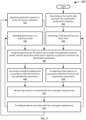
- FIG. 4 depicts a flowchart 400 of an example of a method of predictive autoscaling and resource optimization.
- the flowchart 400 starts at module 402 with converting an SLA metric data structure into a declarative performance objective.
- the SLA metric data structure can be stored in an SLA metric datastore, such as the SLA metric datastore 104 described in association with FIG. 1 .
- a declarative performance interface engine such as the declarative performance interface engine 108 described in association with FIG. 1 , can convert the SLA metric data structure into a declarative performance object.
- the flowchart 400 continues to module 404 with estimating a load forecast out to a future time.
- the load forecast may be of limited use because it amounts to little more than a guess based upon known data regarding the deployment, without the benefit of feedback related to resource utilization and performance post-deployment. It typically takes a few minutes to receive and process such feedback, at which point the load forecast can become a much more predictive estimate. Accordingly, the module 404 could be skipped as unnecessary until such time as data becomes useful for making accurate predictions.
- An application load forecasting engine such as the application load forecasting engine 114 described in association with FIG. 1 , can estimate a load forecast out to a future time.
- the flowchart 400 continues to module 406 with using the load forecast and the declarative performance objective to generate minimum cost optimization parameters.
- the forecast may be of limited use for accurately generating minimum cost optimization parameters.
- a model estimate could be provided in lieu of a performance model and an application behavior model generated in response to feedback associated with a deployment, such models are of limited value.
- the module 406 can also use the performance model and the application behavior model to generate minimum cost optimization parameters. (See the description associated with the modules 416 and 418 below.)
- a minimum cost optimization engine such as the minimum cost optimization engine 116 described in association with FIG. 1 , can use the load forecast, the performance model (if applicable), the application behavior model (if applicable), and the declarative performance objective to generate minimum cost optimization parameters.
- the flowchart 400 continues to module 408 with executing convergent deployments in accordance with the minimum cost optimization parameters.
- An optimal configuration for scale resources actuator engine such as the optimal configuration for scale resources actuator engine 118 described in association with FIG. 1 , can execute convergent deployments in accordance with the minimum cost optimization parameters.
- the flowchart 400 continues in parallel to module 410 with configuring a load distribution and metrics engine in accordance with the minimum cost optimization parameters.
- module 410 can be configured for parallel execution with another, the modules 408 and 410 are relatively likely to be carried out in parallel, so the illustration is made rather explicit. Of course, the modules could be rearranged for serial processing.
- An optimal configuration for scale resources actuator engine such as the optimal configuration for scale resources actuator engine 118 described in association with FIG. 1 , can configure a load distribution and metrics engine in accordance with the minimum cost optimization parameters.
- a convergent deployment and resource metrics collection engine can monitor resources (including channels) associated with the convergent deployments.
- the flowchart 400 continues to module 414 with providing feedback associated with the convergent deployments.
- a convergent deployment and resource metrics collection engine such as the convergent deployment, resource, and application level metrics collection engine 120 described in association with FIG. 1 , can provide feedback associated with the convergent deployments.
- the flowchart 400 returns to module 404 and continues as described previously and also (in parallel) continues to module 416 with modeling application behavior in terms of resource utilization.
- the modeling of application behavior requires a combined total of up to approximately 5 minutes to receive, process, and perform machine learning on feedback from module 414. Accordingly, in this description of the example of FIG. 4 , the module 416 does is not introduced as quickly as module 404, though a model "stand-in" could be used.
- the flowchart 400 could loop multiple times through other modules before module 416 completes.
- a dynamics estimation engine such as the dynamics estimation engine 112 described in association with FIG. 1 , can model application behavior in terms of resource utilization. From module 416, the flowchart 400 returns to module 406 and continues as described previously.
- the flowchart 400 also continues to module 418 from module 414 with modeling performance as a response to load.
- the modeling of application behavior requires a combined total of up to approximately 5 minutes to receive, process, and perform machine learning on feedback from module 414. Accordingly, in this description of the example of FIG. 4 , the module 418 does is not introduced as quickly as module 404, though a model "stand-in" could be used. Moreover, the flowchart 400 could loop multiple times through other modules before module 418 completes.
- a dynamics estimation engine such as the dynamics estimation engine 112 described in association with FIG. 1 , can model performance as a response to load. From module 418, the flowchart 400 returns to module 406 and continues as described previously.
- modules 404, 416, and 418 can be processed in parallel, though one or more of the modules can, for practical purposes, be skipped in a second loop from module 414 to module 404, 416, and module 418 if no updates to a model or forecast are made relative to the model or forecast from a first loop.
- the modules 404, 416, and 418 could also be rearranged for serial processing.
- the modules 404, 416, and 418 could conceivably come before the module 402 if a deployment is made without SLA metric data, which is provided later in the process.
- the module 402 could be repeated if declarative performance objectives change (not shown).
- FIG. 5 depicts a flowchart 500 of an example of generating predictive autoscaling and resource optimization results in association with a machine learning process.
- the flowchart 500 starts at module 502 with monitoring performance indicators and resource usage.
- a human or artificial agent of a service provider (or service consumer) can provide new performance indicators following, for example, a review of convergent deployment performance.
- a declarative performance interface engine such as the declarative performance interface engine 108 described in association with FIG. 1 , can monitor performance indicators.
- a convergent deployment and resource metrics collection engine such as the convergent deployment, resource, and application level metrics collection engine 120 described in association with FIG. 1 , can monitor resource usage.
- the flowchart 500 continues to module 504 with forecasting application load and seasonality.
- Seasonality can be illustrated in association with a use case, which is, in this example, a shoe company e-commerce deployment.
- Successful shoe company e-commerce deployments typically have stable traffic with some seasonality at Black Friday and during the holidays, plus some seemingly random spikes (e.g., when new shoes are released).
- reactive autoscaling is suboptimal at these times.
- Systems engineers will manually over-provision so SLOs are met.
- a predictive autoscaling and resource optimization system, as described in this paper, is able to learn these seasonalities and provision a correct amount of resources (with provisioning insurance) for these events without manual intervention.
- An application load forecasting engine such as the application load forecasting engine 114 described in association with FIG. 1 , can forecast application load and seasonality.
- the flowchart 500 continues to module 506 with learning a behavior function of an application under load.
- a dynamics estimation engine such as the dynamics estimation engine 112 described in association with FIG. 1 , can leam a behavior function of an application under load.
- the flowchart 500 continues to module 508 with estimating resources used at forecasted demand for resource requests.
- An application load forecasting engine such as the application load forecasting engine 114 described in association with FIG. 1 , can estimate resources used at forecasted demand for resource requests.
- the flowchart 500 continues to module 510 with estimating a forecast pattern for setting resource limits.
- An application load forecasting engine such as the application load forecasting engine 114 described in association with FIG. 1 , can estimate a forecast pattern for setting resource limits.
- the flowchart 500 continues to module 512 with minimizing resources needed to meet the forecasted demand.
- a minimum cost optimization engine such as the minimum cost optimization engine 116 described in association with FIG. 1 , can minimize resources needed to meet the forecasted demand.
- the flowchart 500 ends at module 514 with learning from decisions made in order to improve forecasting and resource estimation.
- An optimal configuration for scale resources actuator engine such as the optimal configuration for scale resources actuator engine 118 described in association with FIG. 1 , can benefit in convergent deployment from learning from decisions made in order to improve forecasting and resource estimation.
- FIG. 6 depicts a diagram 600 of an example of a system for generating minimum cost optimization parameters.
- the diagram 600 includes an SLA metrics datastore 604, which may be implemented as the SLA metrics datastore 104 described in association with FIG. 1 ; a declarative performance interface engine 608 coupled to the SLA metric datastore 604 and which may be implemented as the declarative performance interface engine 108 described in association with FIG. 1 ; a dynamics estimation engine 612, which may be implemented as the dynamics estimation engine 112 described in association with FIG. 1 ; an application load forecasting engine 614, which may be implemented as the application load forecasting engine 114 described in association with FIG. 1 ; a minimum cost optimization engine 616, which may be implemented as the minimum cost optimization engine 116 described in association with FIG.
- a declarative performance datastore 626 coupled to the declarative performance interface engine 608 and the minimum cost optimization engine 616; a behavior model datastore 628 coupled to the dynamics estimation engine 612 and the minimum cost optimization engine 616; a performance model datastore 630 coupled to the dynamics estimation engine 612 and the minimum cost optimization engine 616; a convergent deployment and resource metrics datastore 632 coupled to the dynamics estimation engine 612 and the application load forecasting engine 614; a utilization pattern learning engine 634 coupled to the convergent deployment and resource metric datastore 632; a forecasting model datastore 636 coupled to the application load forecasting engine 614 and the utilization pattern learning engine 634; a forecasted load datastore 638 coupled to the application load forecasting engine 614 and the minimum cost optimization engine 616; and a minimum cost optimization parameters datastore 640 coupled to the minimum cost optimization engine 616.
- the declarative performance interface engine 608 converts SLA metrics from the SLA metric datastore 604 to declarative performance data structures represented by the declarative performance datastore 626.
- the declarative performance interface engine 608 may or may not receive instructions from a human or artificial agent of a service provider (or service consumer) to populate the SLA metric datastore 604. If the SLA metric datastore 604 is modified, the declarative performance engine 608 converts the modification so as to match an intended SLO represented in the SLA metric datastore 604 with a declarative performance data structure in the declarative performance datastore 626.
- the dynamics estimation engine 608 uses machine learning techniques, such as deep learning, to generate a behavior model, which is represented by the behavior model datastore 628 and to generate a performance model, which is represented by the performance model datastore 630.
- the models can be improved with feedback associated with applicable convergent deployments. Such feedback is represented by the convergent deployment and resource metrics datastore 632.
- the convergent deployment and resource metric datastore 632 can be populated by a convergent deployment and resource metrics collection engine (not shown), which may be implemented as the convergent deployment, resource, and application level metrics collection engine 120 described in association with FIG. 1 .
- the utilization pattern learning engine 634 uses deep learning to understand workload to generate models for seasonal load, trendy load, bursty load, and random load. Based on a request and an understanding of workload, signature limits can be set on a deployment according to a utilization pattern (e.g., bursty resulting in a higher limit vs. stable resulting in a lower limit).
- the result of the deep learning is a forecasting model represented by the forecasting model datastore 636.
- the forecasting model datastore 636 can be improved with feedback associated with applicable convergent deployments. Such feedback is represented by the convergent deployment and resource metrics datastore 632.
- the application load forecasting engine 614 uses one or more forecasting models from the forecasting model datastore 636 and feedback from the convergent deployment and resource metrics datastore 632 to estimate resource usage at a future time; this forecasted load is represented by the forecasted load datastore 638.
- the minimum cost optimization engine 616 uses the declarative performance datastore 626, the behavior model datastore 628, the performance model datastore 630, and the forecasted load datastore 638 to generate minimum cost optimization parameters, which are represented by the minimum cost optimization parameters datastore 640.
- the minimum cost optimization parameters can be used by a software deployment platform that can include, for example, an optimal configuration for scale resources actuator engine (not shown), which may be implemented as the optimal configuration for scale resources actuator engine 118 described in association with FIG. 1 .
Landscapes
- Engineering & Computer Science (AREA)
- Theoretical Computer Science (AREA)
- General Engineering & Computer Science (AREA)
- Physics & Mathematics (AREA)
- General Physics & Mathematics (AREA)
- Software Systems (AREA)
- Quality & Reliability (AREA)
- Computing Systems (AREA)
- Computer Hardware Design (AREA)
- Mathematical Physics (AREA)
- Computer Networks & Wireless Communication (AREA)
- Signal Processing (AREA)
- Life Sciences & Earth Sciences (AREA)
- Bioinformatics & Cheminformatics (AREA)
- Bioinformatics & Computational Biology (AREA)
- Evolutionary Biology (AREA)
- Management, Administration, Business Operations System, And Electronic Commerce (AREA)
- Debugging And Monitoring (AREA)
Claims (17)
- System, umfassend:
eine deklarative Performance-Interface-Engine (108), die so konfiguriert ist, dass sie:Kennzahlen aus Service Level Agreements, SLA, empfängt;die SLA-Kennzahlen in deklarative Leistungsdatenstrukturen umwandelt, wobei die Datenstrukturen erklärte Leistungsziele für die Softwarebereitstellung darstellen;Leistungsindikatoren der bereitgestellten Software überwacht;eine konvergente Collection-Engine für Kennzahlen auf die Bereitstellungs-, Ressourcen- und Applikationsebene (120), die so konfiguriert ist, dass sie die Ressourcennutzung von bereitgestellter Software überwacht;eine Dynamik-Schätzungs-Engine (112), die so konfiguriert ist, dass sie ein Anwendungsverhaltensmodell erzeugt, wobei das Anwendungsverhaltensmodell auf Leistungsindikatoren und Ressourcennutzung als Funktion der Last basiert;eine Anwendungslastvorhersage-Engine (114), die so konfiguriert ist, dass sie die Last zu einem zukünftigen Zeitpunkt vorhersagt; eine Engine zur Optimierung der Mindestkosten, die so konfiguriert ist, dass sie Parameter zur Optimierung der Mindestkosten auf der Grundlage der deklarativen Leistungsdatenstrukturen, des Anwendungsverhaltensmodells und der vorhergesagten Last erzeugt;eine prädiktive Autoskalierungs- und Ressourcenoptimierungs-Operator-Engine (110), die so konfiguriert ist, dass sie die Parameter zur Optimierung der Mindestkosten an eine optimale Konfiguration für die Skalierungsressourcen-Aktuator-Engine liefert;wobei die optimale Konfiguration für die Skalierungsressourcen-Aktuator-Engine so konfiguriert ist, dass sie konvergente Bereitstellungen ausführt;eine Lastverteilungs- und Kennzahlen-Engine (124), die so konfiguriert ist, dass sie einen Lastausgleich für mindestens einen Verkehr zu den konvergenten Bereitstellungen und/oder den Verkehr von den konvergenten Bereitstellungen durchführt,wobei die Lastverteilungs- und Kennzahlen-Engine (124) durch die optimale Konfiguration für die Skalierungsressourcen-Aktuator-Engine in Übereinstimmung mit den Parametern zur Optimierung der Mindestkosten konfiguriert wird;wobei die konvergente Collection Engine für Kennzahlen auf die Bereitstellungs-, Ressourcen- und Applikationsebene (120) ferner so konfiguriert ist, dass sie:Ressourcen überwacht, die den konvergenten Bereitstellungen zugeordnet sind; Feedback, das konvergenten Bereitstellungen zugeordnet ist, an die Dynamik-Schätzungs-Engine (112) liefert;wobei die Dynamik-Schätzungs-Engine (112) ferner so konfiguriert ist, dass sie ein aktualisiertes Anwendungsverhaltensmodell auf der Grundlage des Feedbacks erzeugt. - System nach Anspruch 1, wobei die SLA-Kennzahlen eine oder mehrere Service-Level-Indikator-Kennzahlen (SLI-Kennzahlen) und Service-Level-Ziel-Kennzahlen (SLO-Kennzahlen) umfassen.
- System nach Anspruch 1, wobei die SLA-Kennzahlen von einem menschlichen Agenten oder einem künstlichen Agenten definiert werden.
- System nach Anspruch 1, wobei die Leistungsindikatoren eine oder mehrere der folgenden Größen umfassen: Anforderungsanzahl und Anforderungsdauer.
- System nach Anspruch 1, wobei die Ressourcennutzung die Nutzung von einem oder mehreren der folgenden Elemente umfasst: Speicher, CPU-Leistung, Festplatten-E/A und Netzwerk-E/A.
- System nach Anspruch 1, wobei die Anwendungslastvorhersage-Engine so konfiguriert ist, dass sie eine oder mehrere saisonale Last, tendenzielle Last, stoßartige Last und zufällige Last vorhersagt und/oder ein Vorhersagemuster zur Verwendung bei der Festlegung von Ressourcengrenzen schätzt.
- System nach Anspruch 1, ferner umfassend eine prädiktive Autoskalierungs- und Ressourcenoptimierungs-Operator-Engine, die so konfiguriert ist, dass sie den gemessenen Fehler aus den erklärten Leistungszielen bestimmt.
- System nach Anspruch 1, wobei die Dynamik-Schätzungs-Engine (112) so konfiguriert ist, dass sie das Anwendungsverhaltensmodell unter Verwendung von Deep Learning erzeugt.
- Verfahren, umfassend:Empfangen von Kennzahlen aus Service Level Agreements, SLA;Umwanden der SLA-Kennzahlen in deklarative Leistungsdatenstrukturen, wobei die Datenstrukturen erklärte Leistungsziele für die Softwarebereitstellung darstellen;Überwachen der Leistungsindikatoren der bereitgestellten Software;Erzeugen eines Anwendungsverhaltensmodells auf der Grundlage von Leistungsindikatoren und Ressourcennutzung als Funktion der Last;Vorhersagen der Last zu einem zukünftigen Zeitpunkt; Erzeugen von Parametern zur Optimierung der Mindestkosten auf der Grundlage der deklarativen Leistungsdatenstrukturen,des Anwendungsverhaltensmodells und der vorhergesagten Last;Ausführen konvergenter Bereitstellungen;Durchführen eines Lastausgleichs für den Verkehr zu den konvergenten Bereitstellungen und/oder den Verkehr von den konvergenten Bereitstellungen in Übereinstimmung mit den Parametern zur Optimierung der Mindestkosten;Überwachen von Ressourcen, die mit den konvergenten Bereitstellungen zugeordnet sind;Liefern von den konvergenten Bereitstellungen zugeordnetem Feedback;Erzeugen eines aktualisierten Anwendungsverhaltensmodells auf der Grundlage des Feedbacks.
- Verfahren nach Anspruch 9, wobei die SLA-Kennzahlen eine oder mehrere Service-Level-Indikator-Kennzahlen (SLI-Kennzahlen) und Service-Level-Ziel-Kennzahlen (SLO-Metriken) umfassen.
- Verfahren nach Anspruch 9, wobei die SLA-Kennzahlen von einem künstlichen Agenten definiert werden.
- Verfahren nach Anspruch 9, wobei die Leistungsindikatoren eine oder mehrere der folgenden Größen umfassen: Anforderungsanzahl und Anforderungsdauer.
- Verfahren nach Anspruch 9, wobei die Ressourcennutzung die Nutzung von einem oder mehreren der folgenden Elemente umfasst: Speicher, CPU-Leistung, Festplatten-E/A und Netzwerk-E/A.
- Verfahren nach Anspruch 9, wobei die vorhergesagte Last eines oder mehrere der folgenden Elemente umfasst: saisonale Last, tendenzielle Last, stoßartige Last und zufällige Last.
- Verfahren nach Anspruch 9, ferner umfassend das Schätzen eines Vorhersagemusters zur Verwendung bei dem Festlegen von Ressourcengrenzen.
- Verfahren nach Anspruch 9, ferner umfassend das Bestimmen des gemessenen Fehlers aus den erklärten Leistungszielen.
- Verfahren nach Anspruch 9, wobei die Dynamik-Schätzungs-Engine (112) so angeordnet ist, dass sie das Anwendungsverhaltensmodell unter Verwendung von Deep Learning erzeugt.
Applications Claiming Priority (3)
| Application Number | Priority Date | Filing Date | Title |
|---|---|---|---|
| US201962860740P | 2019-06-12 | 2019-06-12 | |
| US201962864476P | 2019-06-20 | 2019-06-20 | |
| PCT/US2020/037598 WO2020252390A1 (en) | 2019-06-12 | 2020-06-12 | Predictive autoscaling and resource optimization |
Publications (4)
| Publication Number | Publication Date |
|---|---|
| EP3983894A1 EP3983894A1 (de) | 2022-04-20 |
| EP3983894A4 EP3983894A4 (de) | 2023-06-21 |
| EP3983894C0 EP3983894C0 (de) | 2024-10-30 |
| EP3983894B1 true EP3983894B1 (de) | 2024-10-30 |
Family
ID=73781083
Family Applications (1)
| Application Number | Title | Priority Date | Filing Date |
|---|---|---|---|
| EP20823465.8A Active EP3983894B1 (de) | 2019-06-12 | 2020-06-12 | Prädiktive autoskalierung und ressourcenoptimierung |
Country Status (4)
| Country | Link |
|---|---|
| US (2) | US11966788B2 (de) |
| EP (1) | EP3983894B1 (de) |
| CN (1) | CN114930293B (de) |
| WO (1) | WO2020252390A1 (de) |
Families Citing this family (33)
| Publication number | Priority date | Publication date | Assignee | Title |
|---|---|---|---|---|
| EP3983894B1 (de) | 2019-06-12 | 2024-10-30 | Arigato Machine, Inc., dba Manifold | Prädiktive autoskalierung und ressourcenoptimierung |
| WO2021001958A1 (ja) * | 2019-07-03 | 2021-01-07 | 日本電信電話株式会社 | サービス品質制御装置、サービス品質制御方法、及びプログラム |
| US11757982B2 (en) | 2020-08-05 | 2023-09-12 | Avesha, Inc. | Performing load balancing self adjustment within an application environment |
| KR20230101868A (ko) | 2020-11-10 | 2023-07-06 | 제넨테크, 인크. | 중앙 네트워크 메시를 통한 서비스 간 통신 및 인증 |
| KR20230098647A (ko) * | 2020-11-10 | 2023-07-04 | 제넨테크, 인크. | 분산 파드 기반 시스템 내에서의 서비스 오케스트레이션 |
| US11552886B2 (en) | 2021-03-09 | 2023-01-10 | Cisco Technology, Inc. | Topology optimization in SD-WANs with path downgrading |
| DE102021202935A1 (de) * | 2021-03-25 | 2022-09-29 | Robert Bosch Gesellschaft mit beschränkter Haftung | Verfahren und Vorrichtung zum Steuern einer Fahrfunktion |
| CN113225211B (zh) * | 2021-04-27 | 2022-09-02 | 中国人民解放军空军工程大学 | 细粒度的服务功能链扩展方法 |
| WO2022235624A1 (en) * | 2021-05-03 | 2022-11-10 | Avesha, Inc. | Controlling placement of workloads of an application within an application environment |
| WO2022235651A1 (en) | 2021-05-03 | 2022-11-10 | Avesha, Inc. | Distributed computing system with multi tenancy based on application slices |
| CN113127042A (zh) * | 2021-05-08 | 2021-07-16 | 中山大学 | 一种智能合约推荐方法、设备及存储介质 |
| EP4353034A4 (de) * | 2021-06-09 | 2025-01-22 | Telefonaktiebolaget LM Ericsson (publ) | Adaptive dimensionierung und bereitstellung einer cloud-basierten infrastruktur eines telekommunikationsnetzwerks |
| KR102585591B1 (ko) * | 2021-06-23 | 2023-10-10 | 한국과학기술원 | 이기종 프로세서 기반 엣지 시스템에서 slo 달성을 위한 인공지능 추론 스케쥴러 |
| US12505394B2 (en) * | 2021-08-23 | 2025-12-23 | Shopify Inc. | Systems and methods for modifying online stores |
| US11880874B2 (en) | 2021-08-23 | 2024-01-23 | Shopify Inc. | Systems and methods for server load balancing based on correlated events |
| US12223449B2 (en) | 2021-08-23 | 2025-02-11 | Shopify Inc. | Systems and methods for modifying online stores through scheduling |
| US11893614B2 (en) | 2021-08-23 | 2024-02-06 | Shopify Inc. | Systems and methods for balancing online stores across servers |
| KR102621092B1 (ko) * | 2021-11-23 | 2024-01-05 | (주)글루시스 | 쿠버네티스 포드를 위한 자원 프로비저닝 방법 |
| CN114490049A (zh) * | 2022-01-17 | 2022-05-13 | 华东计算技术研究所(中国电子科技集团公司第三十二研究所) | 在容器化边缘计算中自动分配资源的方法及系统 |
| US11875190B2 (en) * | 2022-03-15 | 2024-01-16 | Liveperson, Inc. | Methods and systems for AI-based load balancing of processing resources in distributed environments |
| US12493495B2 (en) | 2022-04-15 | 2025-12-09 | Dell Products L.P. | Method and system for performing anomaly detection in a distributed multi-tiered computing environment |
| US12327144B2 (en) | 2022-04-15 | 2025-06-10 | Dell Products L.P. | Method and system for managing resource buffers in a distributed multi-tiered computing environment |
| US12353923B2 (en) * | 2022-04-15 | 2025-07-08 | Dell Products L.P. | Method and system for managing a distributed multi-tiered computing environment based on load predictions |
| US12265845B2 (en) | 2022-04-15 | 2025-04-01 | Dell Products L.P. | Method and system for provisioning an application in a distributed multi-tiered computing environment using case based reasoning |
| US12160351B2 (en) * | 2022-05-02 | 2024-12-03 | Jpmorgan Chase Bank N.A. | Systems and methods for site reliability engineering |
| US12561181B1 (en) | 2022-09-30 | 2026-02-24 | Amazon Technologies, Inc. | Host fleet management optimizations in a cloud provider network |
| US12450086B1 (en) * | 2022-09-30 | 2025-10-21 | Amazon Technologies, Inc. | Host fleet management optimizations in a cloud provider network |
| CN116149843B (zh) * | 2022-11-28 | 2026-04-14 | 中国科学院深圳先进技术研究院 | 基于动态规划的资源分配方法、网络及存储介质和处理器 |
| US20240303127A1 (en) * | 2023-03-06 | 2024-09-12 | Dell Products L.P. | Systems and methods for edge system resource capacity performance prediction |
| CN116501594B (zh) * | 2023-06-27 | 2023-09-08 | 上海燧原科技有限公司 | 系统建模评估方法、装置、电子设备及存储介质 |
| US12132621B1 (en) | 2023-09-29 | 2024-10-29 | Hewlett Packard Enterprise Development Lp | Managing network service level thresholds |
| CN118363734B (zh) * | 2024-05-13 | 2024-10-25 | 中国人民解放军军事科学院战争研究院 | 一种云环境高密度服务动态优化调度方法及系统 |
| US12513207B2 (en) | 2024-05-17 | 2025-12-30 | International Business Machines Corporation | System and method for coordinated resource scaling in microservice-based and serverless applications |
Family Cites Families (31)
| Publication number | Priority date | Publication date | Assignee | Title |
|---|---|---|---|---|
| US5179702A (en) * | 1989-12-29 | 1993-01-12 | Supercomputer Systems Limited Partnership | System and method for controlling a highly parallel multiprocessor using an anarchy based scheduler for parallel execution thread scheduling |
| US7173910B2 (en) | 2001-05-14 | 2007-02-06 | Level 3 Communications, Inc. | Service level agreements based on objective voice quality testing for voice over IP (VOIP) networks |
| US8346909B2 (en) * | 2004-01-22 | 2013-01-01 | International Business Machines Corporation | Method for supporting transaction and parallel application workloads across multiple domains based on service level agreements |
| KR101096000B1 (ko) * | 2004-10-28 | 2011-12-19 | 텔레콤 이탈리아 소시에떼 퍼 아찌오니 | 통신 서비스 및/또는 네트워크 관리를 위한 플랫폼내자원관리방법, 이에 따른 플랫폼 및 컴퓨터 프로그램 제품 |
| US7571120B2 (en) * | 2005-01-12 | 2009-08-04 | International Business Machines Corporation | Computer implemented method for estimating future grid job costs by classifying grid jobs and storing results of processing grid job microcosms |
| JP5262724B2 (ja) * | 2007-01-11 | 2013-08-14 | 日本電気株式会社 | プロビジョニングシステム、方法、及び、プログラム |
| US8918496B2 (en) * | 2007-04-30 | 2014-12-23 | Hewlett-Packard Development Company, L.P. | System and method for generating synthetic workload traces |
| US8397088B1 (en) * | 2009-07-21 | 2013-03-12 | The Research Foundation Of State University Of New York | Apparatus and method for efficient estimation of the energy dissipation of processor based systems |
| US8645529B2 (en) * | 2010-10-06 | 2014-02-04 | Infosys Limited | Automated service level management of applications in cloud computing environment |
| US8621058B2 (en) * | 2010-10-28 | 2013-12-31 | Hewlett-Packard Development Company, L.P. | Providing cloud-based computing services |
| US8756609B2 (en) * | 2011-12-30 | 2014-06-17 | International Business Machines Corporation | Dynamically scaling multi-tier applications vertically and horizontally in a cloud environment |
| US9967159B2 (en) | 2012-01-31 | 2018-05-08 | Infosys Limited | Systems and methods for providing decision time brokerage in a hybrid cloud ecosystem |
| CN104956325A (zh) * | 2013-01-31 | 2015-09-30 | 惠普发展公司,有限责任合伙企业 | 物理资源分配 |
| US20150032495A1 (en) * | 2013-07-25 | 2015-01-29 | Futurewei Technologies, Inc. | System and Method for User Controlled Cost Based Network and Path Selection across Multiple Networks |
| WO2015138678A1 (en) * | 2014-03-13 | 2015-09-17 | Jpmorgan Chase Bank, N.A. | Systems and methods for intelligent workload routing |
| US10445134B2 (en) * | 2014-06-03 | 2019-10-15 | Amazon Technologies, Inc. | Identifying candidate workloads for migration |
| US10439870B2 (en) * | 2015-11-24 | 2019-10-08 | International Business Machines Corporation | Assessment and dynamic provisioning of computing resources for multi-tiered application |
| US10887176B2 (en) * | 2017-03-30 | 2021-01-05 | Hewlett Packard Enterprise Development Lp | Predicting resource demand in computing environments |
| CN107241384B (zh) * | 2017-05-03 | 2020-11-03 | 复旦大学 | 一种基于多云架构的内容分发服务资源优化调度方法 |
| US11294726B2 (en) * | 2017-05-04 | 2022-04-05 | Salesforce.Com, Inc. | Systems, methods, and apparatuses for implementing a scalable scheduler with heterogeneous resource allocation of large competing workloads types using QoS |
| US11126927B2 (en) * | 2017-11-24 | 2021-09-21 | Amazon Technologies, Inc. | Auto-scaling hosted machine learning models for production inference |
| US11256548B2 (en) * | 2018-05-03 | 2022-02-22 | LGS Innovations LLC | Systems and methods for cloud computing data processing |
| US11030185B2 (en) * | 2018-05-07 | 2021-06-08 | Microsoft Technology Licensing, Llc | Schema-agnostic indexing of distributed databases |
| US10977083B2 (en) * | 2018-08-30 | 2021-04-13 | Intuit Inc. | Cost optimized dynamic resource allocation in a cloud infrastructure |
| US10789089B2 (en) * | 2018-09-13 | 2020-09-29 | Intuit Inc. | Dynamic application migration between cloud providers |
| EP3983894B1 (de) | 2019-06-12 | 2024-10-30 | Arigato Machine, Inc., dba Manifold | Prädiktive autoskalierung und ressourcenoptimierung |
| US11144443B2 (en) * | 2019-09-09 | 2021-10-12 | Microsoft Technology Licensing, Llc | Optimization of workloads based on constraints |
| US11561836B2 (en) * | 2019-12-11 | 2023-01-24 | Sap Se | Optimizing distribution of heterogeneous software process workloads |
| US11593180B2 (en) * | 2020-12-15 | 2023-02-28 | Kyndryl, Inc. | Cluster selection for workload deployment |
| US12020070B2 (en) * | 2021-04-02 | 2024-06-25 | Red Hat, Inc. | Managing computer workloads across distributed computing clusters |
| US12579274B2 (en) * | 2021-11-16 | 2026-03-17 | Intel Corporation | Intent-driven power management |
-
2020
- 2020-06-12 EP EP20823465.8A patent/EP3983894B1/de active Active
- 2020-06-12 US US17/618,621 patent/US11966788B2/en active Active
- 2020-06-12 CN CN202080056503.4A patent/CN114930293B/zh active Active
- 2020-06-12 US US17/619,062 patent/US20220300344A1/en not_active Abandoned
- 2020-06-12 WO PCT/US2020/037598 patent/WO2020252390A1/en not_active Ceased
Also Published As
| Publication number | Publication date |
|---|---|
| EP3983894A1 (de) | 2022-04-20 |
| EP3983894A4 (de) | 2023-06-21 |
| CN114930293B (zh) | 2026-03-17 |
| EP3983894C0 (de) | 2024-10-30 |
| US20220300344A1 (en) | 2022-09-22 |
| US11966788B2 (en) | 2024-04-23 |
| US20220244993A1 (en) | 2022-08-04 |
| WO2020252390A1 (en) | 2020-12-17 |
| CN114930293A (zh) | 2022-08-19 |
| WO2020252390A9 (en) | 2024-11-07 |
Similar Documents
| Publication | Publication Date | Title |
|---|---|---|
| EP3983894B1 (de) | Prädiktive autoskalierung und ressourcenoptimierung | |
| Imdoukh et al. | Machine learning-based auto-scaling for containerized applications | |
| US10942781B2 (en) | Automated capacity provisioning method using historical performance data | |
| Arkian et al. | Model-based stream processing auto-scaling in geo-distributed environments | |
| US9363190B2 (en) | System, method and computer program product for energy-efficient and service level agreement (SLA)-based management of data centers for cloud computing | |
| Gias et al. | Cocoa: Cold start aware capacity planning for function-as-a-service platforms | |
| Krebs et al. | Resource usage control in multi-tenant applications | |
| CN109491760B (zh) | 一种高效能数据中心云服务器资源自主管理方法 | |
| CN104956325A (zh) | 物理资源分配 | |
| Xu et al. | Practice of Alibaba cloud on elastic resource provisioning for large‐scale microservices cluster | |
| HoseinyFarahabady et al. | Q-flink: A qos-aware controller for apache flink | |
| Anglano et al. | FC2Q: exploiting fuzzy control in server consolidation for cloud applications with SLA constraints | |
| Sousa et al. | Predictive elastic replication for multi‐tenant databases in the cloud | |
| Król et al. | Self-scalable services in service oriented software for cost-effective data farming | |
| Samir et al. | Autoscaling recovery actions for container‐based clusters | |
| Mera-Gómez et al. | A debt-aware learning approach for resource adaptations in cloud elasticity management | |
| Gohad et al. | Model driven provisioning in multi-tenant clouds | |
| Seracini et al. | A comprehensive resource management solution for web-based systems | |
| Xiong et al. | Sla-based service composition in enterprise computing | |
| Bhalla | Understanding Cloud Growth Strategies: Elasticity vs. Scalability in Modern Cloud Infrastructure | |
| He et al. | An SLA-driven cache optimization approach for multi-tenant application on PaaS | |
| KR20160044623A (ko) | 리눅스 가상 서버의 로드 밸런싱 방법 | |
| Di Sanzo et al. | Providing transaction class-based qos in in-memory data grids via machine learning | |
| Lango | Toward software-defined slas: enterprise computing in the public cloud | |
| Wu et al. | Elastic resource provisioning for batched stream processing system in container cloud |
Legal Events
| Date | Code | Title | Description |
|---|---|---|---|
| STAA | Information on the status of an ep patent application or granted ep patent |
Free format text: STATUS: THE INTERNATIONAL PUBLICATION HAS BEEN MADE |
|
| PUAI | Public reference made under article 153(3) epc to a published international application that has entered the european phase |
Free format text: ORIGINAL CODE: 0009012 |
|
| STAA | Information on the status of an ep patent application or granted ep patent |
Free format text: STATUS: REQUEST FOR EXAMINATION WAS MADE |
|
| 17P | Request for examination filed |
Effective date: 20211215 |
|
| AK | Designated contracting states |
Kind code of ref document: A1 Designated state(s): AL AT BE BG CH CY CZ DE DK EE ES FI FR GB GR HR HU IE IS IT LI LT LU LV MC MK MT NL NO PL PT RO RS SE SI SK SM TR |
|
| DAV | Request for validation of the european patent (deleted) | ||
| DAX | Request for extension of the european patent (deleted) | ||
| A4 | Supplementary search report drawn up and despatched |
Effective date: 20230523 |
|
| RIC1 | Information provided on ipc code assigned before grant |
Ipc: H04L 12/40 20060101ALI20230516BHEP Ipc: H04L 12/12 20060101ALI20230516BHEP Ipc: G06F 11/34 20060101ALI20230516BHEP Ipc: G06F 11/30 20060101ALI20230516BHEP Ipc: G06F 8/60 20180101ALI20230516BHEP Ipc: G06F 9/44 20180101ALI20230516BHEP Ipc: H04L 12/02 20060101ALI20230516BHEP Ipc: G06F 9/50 20060101AFI20230516BHEP |
|
| GRAP | Despatch of communication of intention to grant a patent |
Free format text: ORIGINAL CODE: EPIDOSNIGR1 |
|
| STAA | Information on the status of an ep patent application or granted ep patent |
Free format text: STATUS: GRANT OF PATENT IS INTENDED |
|
| INTG | Intention to grant announced |
Effective date: 20240521 |
|
| GRAS | Grant fee paid |
Free format text: ORIGINAL CODE: EPIDOSNIGR3 |
|
| GRAA | (expected) grant |
Free format text: ORIGINAL CODE: 0009210 |
|
| STAA | Information on the status of an ep patent application or granted ep patent |
Free format text: STATUS: THE PATENT HAS BEEN GRANTED |
|
| AK | Designated contracting states |
Kind code of ref document: B1 Designated state(s): AL AT BE BG CH CY CZ DE DK EE ES FI FR GB GR HR HU IE IS IT LI LT LU LV MC MK MT NL NO PL PT RO RS SE SI SK SM TR |
|
| REG | Reference to a national code |
Ref country code: GB Ref legal event code: FG4D |
|
| REG | Reference to a national code |
Ref country code: CH Ref legal event code: EP |
|
| REG | Reference to a national code |
Ref country code: IE Ref legal event code: FG4D |
|
| REG | Reference to a national code |
Ref country code: DE Ref legal event code: R096 Ref document number: 602020040451 Country of ref document: DE |
|
| U01 | Request for unitary effect filed |
Effective date: 20241129 |
|
| U07 | Unitary effect registered |
Designated state(s): AT BE BG DE DK EE FI FR IT LT LU LV MT NL PT RO SE SI Effective date: 20241210 |
|
| PG25 | Lapsed in a contracting state [announced via postgrant information from national office to epo] |
Ref country code: IS Free format text: LAPSE BECAUSE OF FAILURE TO SUBMIT A TRANSLATION OF THE DESCRIPTION OR TO PAY THE FEE WITHIN THE PRESCRIBED TIME-LIMIT Effective date: 20250228 Ref country code: HR Free format text: LAPSE BECAUSE OF FAILURE TO SUBMIT A TRANSLATION OF THE DESCRIPTION OR TO PAY THE FEE WITHIN THE PRESCRIBED TIME-LIMIT Effective date: 20241030 |
|
| PG25 | Lapsed in a contracting state [announced via postgrant information from national office to epo] |
Ref country code: ES Free format text: LAPSE BECAUSE OF FAILURE TO SUBMIT A TRANSLATION OF THE DESCRIPTION OR TO PAY THE FEE WITHIN THE PRESCRIBED TIME-LIMIT Effective date: 20241030 |
|
| PG25 | Lapsed in a contracting state [announced via postgrant information from national office to epo] |
Ref country code: NO Free format text: LAPSE BECAUSE OF FAILURE TO SUBMIT A TRANSLATION OF THE DESCRIPTION OR TO PAY THE FEE WITHIN THE PRESCRIBED TIME-LIMIT Effective date: 20250130 |
|
| RAP2 | Party data changed (patent owner data changed or rights of a patent transferred) |
Owner name: SNYK LIMITED |
|
| U1K | Transfer of rights of the unitary patent after the registration of the unitary effect |
Owner name: SNYK LIMITED; GB |
|
| PG25 | Lapsed in a contracting state [announced via postgrant information from national office to epo] |
Ref country code: GR Free format text: LAPSE BECAUSE OF FAILURE TO SUBMIT A TRANSLATION OF THE DESCRIPTION OR TO PAY THE FEE WITHIN THE PRESCRIBED TIME-LIMIT Effective date: 20250131 |
|
| PG25 | Lapsed in a contracting state [announced via postgrant information from national office to epo] |
Ref country code: PL Free format text: LAPSE BECAUSE OF FAILURE TO SUBMIT A TRANSLATION OF THE DESCRIPTION OR TO PAY THE FEE WITHIN THE PRESCRIBED TIME-LIMIT Effective date: 20241030 |
|
| PG25 | Lapsed in a contracting state [announced via postgrant information from national office to epo] |
Ref country code: RS Free format text: LAPSE BECAUSE OF FAILURE TO SUBMIT A TRANSLATION OF THE DESCRIPTION OR TO PAY THE FEE WITHIN THE PRESCRIBED TIME-LIMIT Effective date: 20250130 |
|
| U20 | Renewal fee for the european patent with unitary effect paid |
Year of fee payment: 6 Effective date: 20250401 |
|
| PG25 | Lapsed in a contracting state [announced via postgrant information from national office to epo] |
Ref country code: SM Free format text: LAPSE BECAUSE OF FAILURE TO SUBMIT A TRANSLATION OF THE DESCRIPTION OR TO PAY THE FEE WITHIN THE PRESCRIBED TIME-LIMIT Effective date: 20241030 |
|
| PGFP | Annual fee paid to national office [announced via postgrant information from national office to epo] |
Ref country code: GB Payment date: 20250401 Year of fee payment: 6 |
|
| PG25 | Lapsed in a contracting state [announced via postgrant information from national office to epo] |
Ref country code: SK Free format text: LAPSE BECAUSE OF FAILURE TO SUBMIT A TRANSLATION OF THE DESCRIPTION OR TO PAY THE FEE WITHIN THE PRESCRIBED TIME-LIMIT Effective date: 20241030 |
|
| PG25 | Lapsed in a contracting state [announced via postgrant information from national office to epo] |
Ref country code: CZ Free format text: LAPSE BECAUSE OF FAILURE TO SUBMIT A TRANSLATION OF THE DESCRIPTION OR TO PAY THE FEE WITHIN THE PRESCRIBED TIME-LIMIT Effective date: 20241030 |
|
| PLBE | No opposition filed within time limit |
Free format text: ORIGINAL CODE: 0009261 |
|
| STAA | Information on the status of an ep patent application or granted ep patent |
Free format text: STATUS: NO OPPOSITION FILED WITHIN TIME LIMIT |
|
| 26N | No opposition filed |
Effective date: 20250731 |
|
| REG | Reference to a national code |
Ref country code: CH Ref legal event code: H13 Free format text: ST27 STATUS EVENT CODE: U-0-0-H10-H13 (AS PROVIDED BY THE NATIONAL OFFICE) Effective date: 20260127 |
|
| PG25 | Lapsed in a contracting state [announced via postgrant information from national office to epo] |
Ref country code: MC Free format text: LAPSE BECAUSE OF FAILURE TO SUBMIT A TRANSLATION OF THE DESCRIPTION OR TO PAY THE FEE WITHIN THE PRESCRIBED TIME-LIMIT Effective date: 20241030 |
|
| PG25 | Lapsed in a contracting state [announced via postgrant information from national office to epo] |
Ref country code: IE Free format text: LAPSE BECAUSE OF NON-PAYMENT OF DUE FEES Effective date: 20250612 |