EP3983705B1 - Selector and sealing organ for multi selector valve - Google Patents
Selector and sealing organ for multi selector valve Download PDFInfo
- Publication number
- EP3983705B1 EP3983705B1 EP20742921.8A EP20742921A EP3983705B1 EP 3983705 B1 EP3983705 B1 EP 3983705B1 EP 20742921 A EP20742921 A EP 20742921A EP 3983705 B1 EP3983705 B1 EP 3983705B1
- Authority
- EP
- European Patent Office
- Prior art keywords
- sealing
- valve
- selector
- seal
- conical
- Prior art date
- Legal status (The legal status is an assumption and is not a legal conclusion. Google has not performed a legal analysis and makes no representation as to the accuracy of the status listed.)
- Active
Links
Images



Classifications
-
- F—MECHANICAL ENGINEERING; LIGHTING; HEATING; WEAPONS; BLASTING
- F16—ENGINEERING ELEMENTS AND UNITS; GENERAL MEASURES FOR PRODUCING AND MAINTAINING EFFECTIVE FUNCTIONING OF MACHINES OR INSTALLATIONS; THERMAL INSULATION IN GENERAL
- F16K—VALVES; TAPS; COCKS; ACTUATING-FLOATS; DEVICES FOR VENTING OR AERATING
- F16K11/00—Multiple-way valves, e.g. mixing valves; Pipe fittings incorporating such valves
- F16K11/02—Multiple-way valves, e.g. mixing valves; Pipe fittings incorporating such valves with all movable sealing faces moving as one unit
- F16K11/08—Multiple-way valves, e.g. mixing valves; Pipe fittings incorporating such valves with all movable sealing faces moving as one unit comprising only taps or cocks
- F16K11/087—Multiple-way valves, e.g. mixing valves; Pipe fittings incorporating such valves with all movable sealing faces moving as one unit comprising only taps or cocks with spherical plug
- F16K11/0873—Multiple-way valves, e.g. mixing valves; Pipe fittings incorporating such valves with all movable sealing faces moving as one unit comprising only taps or cocks with spherical plug the plug being only rotatable around one spindle
- F16K11/0876—Multiple-way valves, e.g. mixing valves; Pipe fittings incorporating such valves with all movable sealing faces moving as one unit comprising only taps or cocks with spherical plug the plug being only rotatable around one spindle one connecting conduit having the same axis as the spindle
-
- E—FIXED CONSTRUCTIONS
- E21—EARTH OR ROCK DRILLING; MINING
- E21B—EARTH OR ROCK DRILLING; OBTAINING OIL, GAS, WATER, SOLUBLE OR MELTABLE MATERIALS OR A SLURRY OF MINERALS FROM WELLS
- E21B43/00—Methods or apparatus for obtaining oil, gas, water, soluble or meltable materials or a slurry of minerals from wells
-
- F—MECHANICAL ENGINEERING; LIGHTING; HEATING; WEAPONS; BLASTING
- F16—ENGINEERING ELEMENTS AND UNITS; GENERAL MEASURES FOR PRODUCING AND MAINTAINING EFFECTIVE FUNCTIONING OF MACHINES OR INSTALLATIONS; THERMAL INSULATION IN GENERAL
- F16J—PISTONS; CYLINDERS; SEALINGS
- F16J15/00—Sealings
- F16J15/16—Sealings between relatively-moving surfaces
- F16J15/34—Sealings between relatively-moving surfaces with slip-ring pressed against a more or less radial face on one member
- F16J15/3464—Mounting of the seal
- F16J15/3472—Means for centering or aligning the contacting faces
-
- F—MECHANICAL ENGINEERING; LIGHTING; HEATING; WEAPONS; BLASTING
- F16—ENGINEERING ELEMENTS AND UNITS; GENERAL MEASURES FOR PRODUCING AND MAINTAINING EFFECTIVE FUNCTIONING OF MACHINES OR INSTALLATIONS; THERMAL INSULATION IN GENERAL
- F16K—VALVES; TAPS; COCKS; ACTUATING-FLOATS; DEVICES FOR VENTING OR AERATING
- F16K25/00—Details relating to contact between valve members and seats
- F16K25/005—Particular materials for seats or closure elements
-
- F—MECHANICAL ENGINEERING; LIGHTING; HEATING; WEAPONS; BLASTING
- F16—ENGINEERING ELEMENTS AND UNITS; GENERAL MEASURES FOR PRODUCING AND MAINTAINING EFFECTIVE FUNCTIONING OF MACHINES OR INSTALLATIONS; THERMAL INSULATION IN GENERAL
- F16K—VALVES; TAPS; COCKS; ACTUATING-FLOATS; DEVICES FOR VENTING OR AERATING
- F16K5/00—Plug valves; Taps or cocks comprising only cut-off apparatus having at least one of the sealing faces shaped as a more or less complete surface of a solid of revolution, the opening and closing movement being predominantly rotary
- F16K5/08—Details
- F16K5/14—Special arrangements for separating the sealing faces or for pressing them together
- F16K5/20—Special arrangements for separating the sealing faces or for pressing them together for plugs with spherical surfaces
- F16K5/201—Special arrangements for separating the sealing faces or for pressing them together for plugs with spherical surfaces with the housing or parts of the housing mechanically pressing the seal against the plug
- F16K5/202—Special arrangements for separating the sealing faces or for pressing them together for plugs with spherical surfaces with the housing or parts of the housing mechanically pressing the seal against the plug with conical surfaces
Definitions
- the present invention relates to a multi-selector valve for use in "Oil and Gas” field, which collects the flows coming from the well-lines and enables the analysis of the parameters of each single supply line, by selectively deflecting each flow to be analyzed.
- the flow isolation is obtained by means of an innovative selector and sealing organ.
- valves are necessary in any operation because of the need to direct the flow of fluids (gas, water and oil) between wells, pumps, tanks and refineries.
- fluids gas, water and oil
- the development of oil and gas comprises drilling, production (supply of surface fluids), treatment of various oil and gas mixtures and transportation to oil refineries and gas outlets.
- the fluids coming from the wells are transported in a in central collection point, in order to further combine or separate them for subsequent processes such as refining, gas sale, etc.
- tests are often required for each flow to ensure the quality of the fluids produced.
- the production of each well is generally directed to a collection point which directs the products of the well to various test and/or production destination.
- pipes or system of pipes and multi-selector valves are used in order to direct the flows to the desired positions and to drive more inlets to a single destination.
- the fittings of the multi-selector valves are based on the technology that puts cylindrical surfaces in contact with each other, i.e. a first convex cylindrical surface (SEAT) is pre-loaded against a second concave cylindrical surface (BODY) between the selector element and each supply line.
- a first convex cylindrical surface SEAT
- BODY concave cylindrical surface
- the multi-selector valves are provided with a single soft convex cylindrical surface (SEAT) which is pre-loaded against the same internal surface of the concave body (BODY) of the different lines and in order to perform the coupling and sealing.
- the known art does not ensure a simultaneous and reliable sealing of all the supply lines, so as to allow the full operation of the system when the valve selectively prepares the deviation of the flow to be analyzed.
- the present invention has the aim of solving the following technical problems by: improving the isolation of the supply line to be characterized and the sealing of the selector element by making it more reliable and long-lasting, in order to guarantee the full operation of the system when the valve presets a selective diversion of flow to be analyzed and by therefore increasing the performances of the multi-selector valve with respect to that referred to in the known art.
- the multi-selector valve has an innovative selector and sealing organ, i.e. a coupling between a conical surface (SEAT) and a spherical surface (BALL) between the selector element and each supply line, which has the characteristics set out in the independent product claim.
- SEAT conical surface
- BALL spherical surface
- Figure 1 is an axonometric overall view of a multi-selector valve 100.
- the multi-selector valve 100 comprises a valve body 4, a plurality of inlet fittings 1 in connection with the respective supply lines 1a, for example seven in number (shown in Figures 2-5 ), coming from a plurality of wells positioned between them at various distances, a delivery connector 20 and a delivery connector for carrying out tests 2'.
- the selector element 10 isolates the discharge for the execution of tests 2', as the same is not in communication with any inlet fitting 1, but communicates with the so-called resting (inactive) position 2.
- the selector element 10 is shown during the working phase.
- the selector element 10 isolates a fitting or inlet 1' of the plurality of inlet fittings 1, in connection with an operating supply line 1a', to carry out the test, putting it in communication with the delivery connector for the execution of tests 2'.
- the selector element 10 is handled to test another supply line or to return to the resting position 2.
- the selector element 10 is visible in cross section and in particular a first connection 10' between an inlet fitting 1 of the intercepted supply line and the delivery connector for the execution of test 2'.
- a second connection 10" is also visible, with a generic supply line which has not been tested.
- the geometry of the connections 10" is identical for all supply lines 1a.
- the pressure sealing between the selector element 10 and an inlet connector 1 is realized through a sealing element or seat 11 which, being formed with a conical surface 3 coupled to a spherical surface 12 of the selector element 10, generates a conical-spherical coupling. This sealing is present on each of the eight inlet fittings 1 of the multi-selector valve 100.
- Both the selector element 10 and the sealing seat 11 are coated on the surface by means of the addition of either metal carbides (tungsten or chromium) or with a surface hardening treatment (nitriding), which allows to generate the conical-spherical pressure sealing between fully metal elements (conical surface 3 of the sealing seat 11 and the spherical surface 12 of the selector element 10), by limiting wear and preventing seizing of the parts.
- metal carbides tungsten or chromium
- nitriding surface hardening treatment
- the conical surface 3 of the sealing seat 11 and the spherical surface 12 of the selector element 10 are surface hardened, for example by means of a tungsten carbide/chromium coating (HVOF) up to a thickness ranging between 150 and 400 ⁇ m and by reaching a hardness equal to or greater than 1000 HV.
- HVOF tungsten carbide/chromium coating
- the stable contact between the conical surface 3 and the spherical surface 12 is ensured by a plurality of elastic means 5, also visible in Figure 8 , which are preloaded between a surface of the inlet fitting 1 and a seat surface sealing 11, located on a band opposite to the conical surface 3 of the sealing seat 11.
- the elastic means 5 ensure, in any operating situation, a sure and reliable contact of the conical surface 3 of the sealing seat 11 and the spherical surface 12 of the selector element 10.
- an elastomeric or thermoplastic gasket 6 is interposed between the inlet fitting 1 and the sealing seat 11, so that the gasket sail ensures the sealing between the two components.
- the conical-spherical sealing allows to create a complete spherical contact surface between the shutter and the seat and therefore it does not allow any leakage.
- the sealing performances are the same as for the traditional ball valves, and it is therefore possible to achieve ISO 5208-Rate A.
- Both the conical surface and the spherical surface shutter are made of metal, and are coated by means of a thermal spray coating method - called High-Velocity Oxy-Fuel (HVOF) > 1000HV.
- HVOF High-Velocity Oxy-Fuel
- the typical coatings of the sealing surfaces can be 316L SS, 22Cr Duplex SS, 25Cr Super-Duplex SS, Inconel ® 625 (E-NiCrMo3 or ER-NiCrMo3).
- the sealing between the valve body 4 and an inlet fitting 1 comprises a first seal 7 and a second seal 8.
- the first seal 7 can be an elastomeric or thermoplastic sealing, depending on the operative conditions.
- the second seal 8 is an elastomeric gasket for containing the pressure in the event of damage to the first gasket 7, due for example to an exposure to fire.
- this combination of seals fully complies with the requirements of the fire specifications and it is then certified. This type of "redundant" sealing is applied to all joints between valve body 4 and inlet fittings 1.
Landscapes
- Engineering & Computer Science (AREA)
- General Engineering & Computer Science (AREA)
- Mechanical Engineering (AREA)
- Mining & Mineral Resources (AREA)
- Geology (AREA)
- Life Sciences & Earth Sciences (AREA)
- Fluid Mechanics (AREA)
- Physics & Mathematics (AREA)
- General Life Sciences & Earth Sciences (AREA)
- Geochemistry & Mineralogy (AREA)
- Environmental & Geological Engineering (AREA)
- Taps Or Cocks (AREA)
- Multiple-Way Valves (AREA)
Description
- The present invention relates to a multi-selector valve for use in "Oil and Gas" field, which collects the flows coming from the well-lines and enables the analysis of the parameters of each single supply line, by selectively deflecting each flow to be analyzed. The flow isolation is obtained by means of an innovative selector and sealing organ.
- As known, in the production of oil, natural gas and other fluids, valves are necessary in any operation because of the need to direct the flow of fluids (gas, water and oil) between wells, pumps, tanks and refineries. In general, the development of oil and gas comprises drilling, production (supply of surface fluids), treatment of various oil and gas mixtures and transportation to oil refineries and gas outlets. Generally, the fluids coming from the wells are transported in a in central collection point, in order to further combine or separate them for subsequent processes such as refining, gas sale, etc. In addition, tests are often required for each flow to ensure the quality of the fluids produced. As a result, the production of each well is generally directed to a collection point which directs the products of the well to various test and/or production destination. In order to do so, in general pipes or system of pipes and multi-selector valves are used in order to direct the flows to the desired positions and to drive more inlets to a single destination.
- Such technique is known and can be derived for example from document
US2012216887 A1 , in which a multi-selector valve is described comprising a flow fitting pivotally arranged in order that the flow can be aligned by rotation with each of the plurality of inlet openings. Another example of known multi-selector valves according to the preamble ofclaim 1 and applied in the "Oil and Gas" field is described in documentCN105179749 . Finally, documentUS2017/0219105A1 describes a multi-selector valve applied to internal combustion engines, therefore outside the scope of interest of the present invention. - In the known solutions, moreover, the fittings of the multi-selector valves are based on the technology that puts cylindrical surfaces in contact with each other, i.e. a first convex cylindrical surface (SEAT) is pre-loaded against a second concave cylindrical surface (BODY) between the selector element and each supply line. Generally the multi-selector valves are provided with a single soft convex cylindrical surface (SEAT) which is pre-loaded against the same internal surface of the concave body (BODY) of the different lines and in order to perform the coupling and sealing.
- The known solutions have the drawbacks due to sealing losses between the selector element and one or more lines, as a result of the wear of the soft connecting surfaces that very often cause leaks also from other lines. This results in having to carry out plant stops or, generally every six months, to monitor the different supply lines.
- Furthermore, the known art does not ensure a simultaneous and reliable sealing of all the supply lines, so as to allow the full operation of the system when the valve selectively prepares the deviation of the flow to be analyzed.
- There is, therefore, the need to define an innovative selector and sealing organ for a multi-selector valve that is free from the drawbacks mentioned above.
- The present invention has the aim of solving the following technical problems by: improving the isolation of the supply line to be characterized and the sealing of the selector element by making it more reliable and long-lasting, in order to guarantee the full operation of the system when the valve presets a selective diversion of flow to be analyzed and by therefore increasing the performances of the multi-selector valve with respect to that referred to in the known art.
- For such aim, according to the invention, the multi-selector valve has an innovative selector and sealing organ, i.e. a coupling between a conical surface (SEAT) and a spherical surface (BALL) between the selector element and each supply line, which has the characteristics set out in the independent product claim.
- Further preferred and/or particularly advantageous embodiments of the invention are described according to the characteristics set out in the appended dependent claims.
- The invention will now be described with reference to the attached drawings, which illustrate some non-limiting examples of embodiments, in which:
-
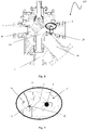
Figure 1 is an axonometric view of a set of multi-selector valve, -
Figure 2 is a schematic section of the inside of a multi-selector valve comprising a selector and a sealing element according to the present invention, wherein the selector element is in the rest position, -
Figure 3 is a schematic view of a longitudinal section of the multi-selector valve ofFig. 2 , -
Figure 4 is a schematic section of the inside of a multi-selector valve comprising a selector and sealing element according to the present invention, wherein the selector element is in the interception and deviation position of the line to be calibrated, -
Figure 5 schematically shows a longitudinal section of the multi-selector valve ofFig. 4 , -
Figure 6 is a cross section of the multi-selector valve ofFig. 1 , in which the shape of the shutter and the sealing element is shown according to the present invention, -
Figure 7 is a detail of the sealing between the selector element and the supply line, according to the present invention, -
Figure 8 is a detail of the multi-selector valve ofFig. 1 , wherein elastic means are visible, which ensure the sealing between the selector element and the supply line, according to the present invention, -
Figure 9 shows the multi-selector valve in which the elastic means ofFig. 8 are adapted to simultaneously ensure the sealing between selector elements and the supply lines, and -
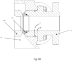
Figure 10 is a detail of the sealing between the valve body, the selector element and a supply line. - With reference to the aforesaid figures,
Figure 1 is an axonometric overall view of amulti-selector valve 100. Themulti-selector valve 100 comprises avalve body 4, a plurality ofinlet fittings 1 in connection with therespective supply lines 1a, for example seven in number (shown inFigures 2-5 ), coming from a plurality of wells positioned between them at various distances, adelivery connector 20 and a delivery connector for carrying out tests 2'. - In the resting position, shown in
Figure 2 and Figure 3 , theselector element 10 isolates the discharge for the execution of tests 2', as the same is not in communication with any inlet fitting 1, but communicates with the so-called resting (inactive)position 2. - With reference to
Figure 4 and Figure 5 , theselector element 10 is shown during the working phase. In particular, for example, theselector element 10 isolates a fitting or inlet 1' of the plurality ofinlet fittings 1, in connection with anoperating supply line 1a', to carry out the test, putting it in communication with the delivery connector for the execution of tests 2'. Once the analysis has been completed, theselector element 10 is handled to test another supply line or to return to theresting position 2. With reference toFigure 6 , theselector element 10 is visible in cross section and in particular a first connection 10' between aninlet fitting 1 of the intercepted supply line and the delivery connector for the execution of test 2'. Asecond connection 10" is also visible, with a generic supply line which has not been tested. - Advantageously, the geometry of the
connections 10" is identical for allsupply lines 1a. - More particularly, with reference to
Figure 6 and 7 , in a transverse cross-section the sealing area is shown between theselector element 10 and ageneric inlet fitting 1. - The pressure sealing between the
selector element 10 and aninlet connector 1 is realized through a sealing element orseat 11 which, being formed with aconical surface 3 coupled to aspherical surface 12 of theselector element 10, generates a conical-spherical coupling. This sealing is present on each of the eightinlet fittings 1 of themulti-selector valve 100. - Both the
selector element 10 and the sealingseat 11 are coated on the surface by means of the addition of either metal carbides (tungsten or chromium) or with a surface hardening treatment (nitriding), which allows to generate the conical-spherical pressure sealing between fully metal elements (conical surface 3 of the sealingseat 11 and thespherical surface 12 of the selector element 10), by limiting wear and preventing seizing of the parts. - In particular, the
conical surface 3 of the sealingseat 11 and thespherical surface 12 of theselector element 10 are surface hardened, for example by means of a tungsten carbide/chromium coating (HVOF) up to a thickness ranging between 150 and 400 µm and by reaching a hardness equal to or greater than 1000 HV. - The stable contact between the
conical surface 3 and thespherical surface 12 is ensured by a plurality ofelastic means 5, also visible inFigure 8 , which are preloaded between a surface of theinlet fitting 1 and a seat surface sealing 11, located on a band opposite to theconical surface 3 of the sealingseat 11. In this way the elastic means 5 ensure, in any operating situation, a sure and reliable contact of theconical surface 3 of the sealingseat 11 and thespherical surface 12 of theselector element 10. - It is to be observed, as shown in
Figure 9 , that the plurality ofelastic means 5 is present on each inlet fitting 1 with the same preloading mode. In this way, it is possible to ensure a simultaneous and reliable sealing of allsupply lines 1a, so as to allow the full operation of the system when the valve selectively prepares the deviation of the flow to be analyzed. - Furthermore, returning to
Figure 7 , an elastomeric orthermoplastic gasket 6 is interposed between theinlet fitting 1 and the sealingseat 11, so that the gasket sail ensures the sealing between the two components. - Advantageously, the conical-spherical sealing allows to create a complete spherical contact surface between the shutter and the seat and therefore it does not allow any leakage.
- Advantageously, the sealing performances are the same as for the traditional ball valves, and it is therefore possible to achieve ISO 5208-Rate A.
- Even more advantageously, the metal-metal sealing is obtained, in order to ensure long lasting performances with low maintenance. Both the conical surface and the spherical surface shutter are made of metal, and are coated by means of a thermal spray coating method - called High-Velocity Oxy-Fuel (HVOF) > 1000HV. The typical coatings of the sealing surfaces, for example, can be 316L SS, 22Cr Duplex SS, 25Cr Super-Duplex SS, Inconel® 625 (E-NiCrMo3 or ER-NiCrMo3).
- As shown in more detail in
Figure 10 , the sealing between thevalve body 4 and aninlet fitting 1 comprises afirst seal 7 and asecond seal 8. Thefirst seal 7 can be an elastomeric or thermoplastic sealing, depending on the operative conditions. Thesecond seal 8 is an elastomeric gasket for containing the pressure in the event of damage to thefirst gasket 7, due for example to an exposure to fire. Advantageously, this combination of seals fully complies with the requirements of the fire specifications and it is then certified. This type of "redundant" sealing is applied to all joints betweenvalve body 4 andinlet fittings 1. - In addition to the embodiments of the invention, as described above, it is to be understood that there are numerous further variants. It must also be understood that said embodiments are only examples and do not limit neither the object of the invention, nor its applications, nor its possible configurations. On the contrary, although the above description makes it possible for the skilled man to implement the present invention, at least according to an exemplary configuration, it must be understood that numerous variants of the described components are conceivable, without thereby abandoning the object of the invention, as defined in the attached claims.
Claims (8)
- Multi-selector valve (100) comprising a valve body (4), a plurality of inlet fittings (1), configured to be in connection with respective supply lines (1a) coming from multiple wells and positioned between them at various distances, a first discharge connector (20) and a second discharge connector (2') for carrying out tests, wherein- in said multi-selector valve (100), the sealing between a selector element (10) and each inlet fitting (1) is made by means of a conical-spherical sealing, and- the conical-spherical sealing is made between a conical surface (3) of a sealing seat (11) and a spherical surface (12) of the selector element (10),wherein the conical-spherical sealing between the conical surface (3) of sealing seat (11) and the spherical surface (12) of the selector element (10) is ensured by a plurality of elastic means (5), said multi-selector valve (100) being characterized in that each plurality of elastic means (5) is present on each inlet fitting (1), so as to ensure a simultaneous sealing of all supply lines (1a).
- Multi-selector valve (100) according to claim 1, wherein each elastic means of the plurality of elastic means (5) is pre-charged between a surface of the inlet fitting (1) and a surface of the sealing seat (11), placed on a band opposite to the conical surface (3) of the sealing seat (11).
- Valve (100) according to any of the preceding claims, wherein between the inlet fitting (1) and the sealing seat (11) an elastomeric gasket (6) is interposed, which ensures the sealing between the inlet fitting (1) and the sealing seat (11).
- Valve (100) according to any of the preceding claims, wherein the conical surface (3) and the spherical surface (12) are surface-hardened by means of a coating made of Tungsten/Chromium Carbide (HVOF).
- Valve (100) according to claim 4, wherein the coating made of Tungsten/Chromium Carbide has a thickness between 150 and 400 µm.
- Valve (100) according to claim 4 or 5, wherein the conical surface (3) and the spherical surface (12) reach a hardness equal to or greater than 1000 HV.
- Valve (100) according to any of the preceding claims, wherein the sealing between the valve body (4) and the inlet fitting (1) comprises a first seal (7) and a second seal (8) with a redundancy function.
- Valve (100) according to claim 7, wherein the first seal (7) is an elastomeric or thermoplastic seal and the second seal (8) is an elastomeric seal, in order to contain the pressure in the event of damage of the first seal (7).
Applications Claiming Priority (2)
| Application Number | Priority Date | Filing Date | Title |
|---|---|---|---|
| IT102019000008811A IT201900008811A1 (en) | 2019-06-13 | 2019-06-13 | SELECTOR AND SEALING ORGAN FOR MULTI SELECTOR VALVE |
| PCT/IB2020/055363 WO2020250105A1 (en) | 2019-06-13 | 2020-06-08 | Selector and sealing organ for multi selector valve |
Publications (2)
| Publication Number | Publication Date |
|---|---|
| EP3983705A1 EP3983705A1 (en) | 2022-04-20 |
| EP3983705B1 true EP3983705B1 (en) | 2023-03-15 |
Family
ID=68138682
Family Applications (1)
| Application Number | Title | Priority Date | Filing Date |
|---|---|---|---|
| EP20742921.8A Active EP3983705B1 (en) | 2019-06-13 | 2020-06-08 | Selector and sealing organ for multi selector valve |
Country Status (3)
| Country | Link |
|---|---|
| EP (1) | EP3983705B1 (en) |
| IT (1) | IT201900008811A1 (en) |
| WO (1) | WO2020250105A1 (en) |
Family Cites Families (8)
| Publication number | Priority date | Publication date | Assignee | Title |
|---|---|---|---|---|
| CN2606826Y (en) * | 2003-03-10 | 2004-03-17 | 洪元生 | Float ball valve |
| US8430131B2 (en) | 2011-02-24 | 2013-04-30 | Fisher Controls International Llc | Noise control via outlet jet frequency dispersal |
| ITVI20110068A1 (en) * | 2011-03-29 | 2012-09-30 | Tyco Valves & Controls Italia S R L | SEALING INSERT FOR BALL VALVE, SAW FOR BALL VALVE AND BALL VALVE |
| FR2981720A1 (en) * | 2011-10-25 | 2013-04-26 | Total Sa | ISOLATION TAP |
| CN204284517U (en) * | 2014-12-11 | 2015-04-22 | 欧冠阀门科技有限公司 | A kind of Wear-resistant, high-temperature resistant ball valve |
| CN105179749B (en) * | 2015-10-30 | 2017-11-03 | 王明显 | Multiple-way valve |
| EP3199847B1 (en) * | 2016-01-28 | 2018-07-11 | MANN+HUMMEL GmbH | Fluid control device |
| KR101765881B1 (en) * | 2017-01-04 | 2017-08-08 | 한우성 | Apparatus for alarming replacement of a sealing member in a ball valve |
-
2019
- 2019-06-13 IT IT102019000008811A patent/IT201900008811A1/en unknown
-
2020
- 2020-06-08 WO PCT/IB2020/055363 patent/WO2020250105A1/en not_active Ceased
- 2020-06-08 EP EP20742921.8A patent/EP3983705B1/en active Active
Also Published As
| Publication number | Publication date |
|---|---|
| WO2020250105A1 (en) | 2020-12-17 |
| EP3983705A1 (en) | 2022-04-20 |
| IT201900008811A1 (en) | 2020-12-13 |
Similar Documents
| Publication | Publication Date | Title |
|---|---|---|
| RU2696167C1 (en) | Sealing devices for high pressure flow control | |
| EP2564097B1 (en) | Floating ball valve seal with bellows and c-seal | |
| EP2440819B1 (en) | Fluid valves having dynamic valve trim joints | |
| US20100258193A1 (en) | Ball Valve Impedance Seat | |
| EP2829777B1 (en) | Ball valve seal with dynamic c-seal and static c-seal | |
| US11209089B2 (en) | Valve sealing arrangement and a valve seat | |
| US20060061102A1 (en) | Jacketed pipe flange and method | |
| CN212839517U (en) | Flow control valve and gasket for flow control valve | |
| EP1484495A2 (en) | Externally gimballed joint of a jet pipe | |
| US20180223780A1 (en) | Multi-fuel rail apparatus | |
| US10495229B2 (en) | Severe service valve | |
| US7380842B1 (en) | Spherical flange assembly | |
| US8453676B2 (en) | Fugitive emission reducing valve arrangement | |
| CN104105846B (en) | There are the fluid machinery parts at junction surface and there is the steam turbine of fluid machinery parts | |
| EP3983705A1 (en) | Selector and sealing organ for multi selector valve | |
| US10145478B2 (en) | Top entry soft seats floating ball valve | |
| US6408885B2 (en) | Staked dual valve assembly | |
| GB2272782A (en) | Throttle device particularly a throttle valve | |
| US20230383850A1 (en) | Purge assemblies for valves and related devices, apparatus, systems, and methods | |
| EP3296514A1 (en) | Fluidically controlled steam turbine inlet scroll | |
| EP4453456A1 (en) | A valve | |
| NO340265B1 (en) | Ball valve and valve seat | |
| KR102701370B1 (en) | Pipe joint structure | |
| WO2022128157A1 (en) | Compact dual header manifold layout | |
| US20240344617A1 (en) | Drain valve sealing arrangement |
Legal Events
| Date | Code | Title | Description |
|---|---|---|---|
| STAA | Information on the status of an ep patent application or granted ep patent |
Free format text: STATUS: UNKNOWN |
|
| STAA | Information on the status of an ep patent application or granted ep patent |
Free format text: STATUS: THE INTERNATIONAL PUBLICATION HAS BEEN MADE |
|
| PUAI | Public reference made under article 153(3) epc to a published international application that has entered the european phase |
Free format text: ORIGINAL CODE: 0009012 |
|
| STAA | Information on the status of an ep patent application or granted ep patent |
Free format text: STATUS: REQUEST FOR EXAMINATION WAS MADE |
|
| 17P | Request for examination filed |
Effective date: 20211221 |
|
| AK | Designated contracting states |
Kind code of ref document: A1 Designated state(s): AL AT BE BG CH CY CZ DE DK EE ES FI FR GB GR HR HU IE IS IT LI LT LU LV MC MK MT NL NO PL PT RO RS SE SI SK SM TR |
|
| DAV | Request for validation of the european patent (deleted) | ||
| DAX | Request for extension of the european patent (deleted) | ||
| GRAP | Despatch of communication of intention to grant a patent |
Free format text: ORIGINAL CODE: EPIDOSNIGR1 |
|
| STAA | Information on the status of an ep patent application or granted ep patent |
Free format text: STATUS: GRANT OF PATENT IS INTENDED |
|
| INTG | Intention to grant announced |
Effective date: 20221013 |
|
| GRAS | Grant fee paid |
Free format text: ORIGINAL CODE: EPIDOSNIGR3 |
|
| GRAA | (expected) grant |
Free format text: ORIGINAL CODE: 0009210 |
|
| STAA | Information on the status of an ep patent application or granted ep patent |
Free format text: STATUS: THE PATENT HAS BEEN GRANTED |
|
| AK | Designated contracting states |
Kind code of ref document: B1 Designated state(s): AL AT BE BG CH CY CZ DE DK EE ES FI FR GB GR HR HU IE IS IT LI LT LU LV MC MK MT NL NO PL PT RO RS SE SI SK SM TR |
|
| REG | Reference to a national code |
Ref country code: CH Ref legal event code: EP Ref country code: GB Ref legal event code: FG4D |
|
| REG | Reference to a national code |
Ref country code: DE Ref legal event code: R096 Ref document number: 602020008905 Country of ref document: DE |
|
| REG | Reference to a national code |
Ref country code: IE Ref legal event code: FG4D |
|
| REG | Reference to a national code |
Ref country code: AT Ref legal event code: REF Ref document number: 1554180 Country of ref document: AT Kind code of ref document: T Effective date: 20230415 |
|
| REG | Reference to a national code |
Ref country code: NL Ref legal event code: FP |
|
| REG | Reference to a national code |
Ref country code: LT Ref legal event code: MG9D |
|
| REG | Reference to a national code |
Ref country code: NO Ref legal event code: T2 Effective date: 20230315 |
|
| PG25 | Lapsed in a contracting state [announced via postgrant information from national office to epo] |
Ref country code: RS Free format text: LAPSE BECAUSE OF FAILURE TO SUBMIT A TRANSLATION OF THE DESCRIPTION OR TO PAY THE FEE WITHIN THE PRESCRIBED TIME-LIMIT Effective date: 20230315 Ref country code: LV Free format text: LAPSE BECAUSE OF FAILURE TO SUBMIT A TRANSLATION OF THE DESCRIPTION OR TO PAY THE FEE WITHIN THE PRESCRIBED TIME-LIMIT Effective date: 20230315 Ref country code: LT Free format text: LAPSE BECAUSE OF FAILURE TO SUBMIT A TRANSLATION OF THE DESCRIPTION OR TO PAY THE FEE WITHIN THE PRESCRIBED TIME-LIMIT Effective date: 20230315 Ref country code: HR Free format text: LAPSE BECAUSE OF FAILURE TO SUBMIT A TRANSLATION OF THE DESCRIPTION OR TO PAY THE FEE WITHIN THE PRESCRIBED TIME-LIMIT Effective date: 20230315 |
|
| REG | Reference to a national code |
Ref country code: AT Ref legal event code: MK05 Ref document number: 1554180 Country of ref document: AT Kind code of ref document: T Effective date: 20230315 |
|
| PG25 | Lapsed in a contracting state [announced via postgrant information from national office to epo] |
Ref country code: SE Free format text: LAPSE BECAUSE OF FAILURE TO SUBMIT A TRANSLATION OF THE DESCRIPTION OR TO PAY THE FEE WITHIN THE PRESCRIBED TIME-LIMIT Effective date: 20230315 Ref country code: GR Free format text: LAPSE BECAUSE OF FAILURE TO SUBMIT A TRANSLATION OF THE DESCRIPTION OR TO PAY THE FEE WITHIN THE PRESCRIBED TIME-LIMIT Effective date: 20230616 Ref country code: FI Free format text: LAPSE BECAUSE OF FAILURE TO SUBMIT A TRANSLATION OF THE DESCRIPTION OR TO PAY THE FEE WITHIN THE PRESCRIBED TIME-LIMIT Effective date: 20230315 |
|
| PG25 | Lapsed in a contracting state [announced via postgrant information from national office to epo] |
Ref country code: SM Free format text: LAPSE BECAUSE OF FAILURE TO SUBMIT A TRANSLATION OF THE DESCRIPTION OR TO PAY THE FEE WITHIN THE PRESCRIBED TIME-LIMIT Effective date: 20230315 Ref country code: RO Free format text: LAPSE BECAUSE OF FAILURE TO SUBMIT A TRANSLATION OF THE DESCRIPTION OR TO PAY THE FEE WITHIN THE PRESCRIBED TIME-LIMIT Effective date: 20230315 Ref country code: PT Free format text: LAPSE BECAUSE OF FAILURE TO SUBMIT A TRANSLATION OF THE DESCRIPTION OR TO PAY THE FEE WITHIN THE PRESCRIBED TIME-LIMIT Effective date: 20230717 Ref country code: ES Free format text: LAPSE BECAUSE OF FAILURE TO SUBMIT A TRANSLATION OF THE DESCRIPTION OR TO PAY THE FEE WITHIN THE PRESCRIBED TIME-LIMIT Effective date: 20230315 Ref country code: EE Free format text: LAPSE BECAUSE OF FAILURE TO SUBMIT A TRANSLATION OF THE DESCRIPTION OR TO PAY THE FEE WITHIN THE PRESCRIBED TIME-LIMIT Effective date: 20230315 Ref country code: CZ Free format text: LAPSE BECAUSE OF FAILURE TO SUBMIT A TRANSLATION OF THE DESCRIPTION OR TO PAY THE FEE WITHIN THE PRESCRIBED TIME-LIMIT Effective date: 20230315 Ref country code: AT Free format text: LAPSE BECAUSE OF FAILURE TO SUBMIT A TRANSLATION OF THE DESCRIPTION OR TO PAY THE FEE WITHIN THE PRESCRIBED TIME-LIMIT Effective date: 20230315 |
|
| PG25 | Lapsed in a contracting state [announced via postgrant information from national office to epo] |
Ref country code: SK Free format text: LAPSE BECAUSE OF FAILURE TO SUBMIT A TRANSLATION OF THE DESCRIPTION OR TO PAY THE FEE WITHIN THE PRESCRIBED TIME-LIMIT Effective date: 20230315 Ref country code: PL Free format text: LAPSE BECAUSE OF FAILURE TO SUBMIT A TRANSLATION OF THE DESCRIPTION OR TO PAY THE FEE WITHIN THE PRESCRIBED TIME-LIMIT Effective date: 20230315 Ref country code: IS Free format text: LAPSE BECAUSE OF FAILURE TO SUBMIT A TRANSLATION OF THE DESCRIPTION OR TO PAY THE FEE WITHIN THE PRESCRIBED TIME-LIMIT Effective date: 20230715 |
|
| REG | Reference to a national code |
Ref country code: DE Ref legal event code: R097 Ref document number: 602020008905 Country of ref document: DE |
|
| REG | Reference to a national code |
Ref country code: DE Ref legal event code: R119 Ref document number: 602020008905 Country of ref document: DE |
|
| PG25 | Lapsed in a contracting state [announced via postgrant information from national office to epo] |
Ref country code: MC Free format text: LAPSE BECAUSE OF FAILURE TO SUBMIT A TRANSLATION OF THE DESCRIPTION OR TO PAY THE FEE WITHIN THE PRESCRIBED TIME-LIMIT Effective date: 20230315 |
|
| PLBE | No opposition filed within time limit |
Free format text: ORIGINAL CODE: 0009261 |
|
| STAA | Information on the status of an ep patent application or granted ep patent |
Free format text: STATUS: NO OPPOSITION FILED WITHIN TIME LIMIT |
|
| PG25 | Lapsed in a contracting state [announced via postgrant information from national office to epo] |
Ref country code: SI Free format text: LAPSE BECAUSE OF FAILURE TO SUBMIT A TRANSLATION OF THE DESCRIPTION OR TO PAY THE FEE WITHIN THE PRESCRIBED TIME-LIMIT Effective date: 20230315 Ref country code: MC Free format text: LAPSE BECAUSE OF FAILURE TO SUBMIT A TRANSLATION OF THE DESCRIPTION OR TO PAY THE FEE WITHIN THE PRESCRIBED TIME-LIMIT Effective date: 20230315 Ref country code: DK Free format text: LAPSE BECAUSE OF FAILURE TO SUBMIT A TRANSLATION OF THE DESCRIPTION OR TO PAY THE FEE WITHIN THE PRESCRIBED TIME-LIMIT Effective date: 20230315 |
|
| REG | Reference to a national code |
Ref country code: CH Ref legal event code: PL |
|
| 26N | No opposition filed |
Effective date: 20231218 |
|
| REG | Reference to a national code |
Ref country code: BE Ref legal event code: MM Effective date: 20230630 |
|
| PG25 | Lapsed in a contracting state [announced via postgrant information from national office to epo] |
Ref country code: LU Free format text: LAPSE BECAUSE OF NON-PAYMENT OF DUE FEES Effective date: 20230608 |
|
| REG | Reference to a national code |
Ref country code: IE Ref legal event code: MM4A |
|
| PG25 | Lapsed in a contracting state [announced via postgrant information from national office to epo] |
Ref country code: LU Free format text: LAPSE BECAUSE OF NON-PAYMENT OF DUE FEES Effective date: 20230608 |
|
| PG25 | Lapsed in a contracting state [announced via postgrant information from national office to epo] |
Ref country code: IE Free format text: LAPSE BECAUSE OF NON-PAYMENT OF DUE FEES Effective date: 20230608 |
|
| PG25 | Lapsed in a contracting state [announced via postgrant information from national office to epo] |
Ref country code: IE Free format text: LAPSE BECAUSE OF NON-PAYMENT OF DUE FEES Effective date: 20230608 Ref country code: DE Free format text: LAPSE BECAUSE OF NON-PAYMENT OF DUE FEES Effective date: 20240103 Ref country code: CH Free format text: LAPSE BECAUSE OF NON-PAYMENT OF DUE FEES Effective date: 20230630 |
|
| PG25 | Lapsed in a contracting state [announced via postgrant information from national office to epo] |
Ref country code: FR Free format text: LAPSE BECAUSE OF NON-PAYMENT OF DUE FEES Effective date: 20230630 Ref country code: BE Free format text: LAPSE BECAUSE OF NON-PAYMENT OF DUE FEES Effective date: 20230630 |
|
| PGFP | Annual fee paid to national office [announced via postgrant information from national office to epo] |
Ref country code: NL Payment date: 20240522 Year of fee payment: 5 |
|
| PGFP | Annual fee paid to national office [announced via postgrant information from national office to epo] |
Ref country code: NO Payment date: 20240524 Year of fee payment: 5 |
|
| PGFP | Annual fee paid to national office [announced via postgrant information from national office to epo] |
Ref country code: IT Payment date: 20240521 Year of fee payment: 5 |
|
| PG25 | Lapsed in a contracting state [announced via postgrant information from national office to epo] |
Ref country code: BG Free format text: LAPSE BECAUSE OF FAILURE TO SUBMIT A TRANSLATION OF THE DESCRIPTION OR TO PAY THE FEE WITHIN THE PRESCRIBED TIME-LIMIT Effective date: 20230315 |
|
| PG25 | Lapsed in a contracting state [announced via postgrant information from national office to epo] |
Ref country code: BG Free format text: LAPSE BECAUSE OF FAILURE TO SUBMIT A TRANSLATION OF THE DESCRIPTION OR TO PAY THE FEE WITHIN THE PRESCRIBED TIME-LIMIT Effective date: 20230315 |
|
| GBPC | Gb: european patent ceased through non-payment of renewal fee |
Effective date: 20240608 |
|
| PG25 | Lapsed in a contracting state [announced via postgrant information from national office to epo] |
Ref country code: GB Free format text: LAPSE BECAUSE OF NON-PAYMENT OF DUE FEES Effective date: 20240608 |
|
| PG25 | Lapsed in a contracting state [announced via postgrant information from national office to epo] |
Ref country code: CY Free format text: LAPSE BECAUSE OF FAILURE TO SUBMIT A TRANSLATION OF THE DESCRIPTION OR TO PAY THE FEE WITHIN THE PRESCRIBED TIME-LIMIT; INVALID AB INITIO Effective date: 20200608 |
|
| PG25 | Lapsed in a contracting state [announced via postgrant information from national office to epo] |
Ref country code: HU Free format text: LAPSE BECAUSE OF FAILURE TO SUBMIT A TRANSLATION OF THE DESCRIPTION OR TO PAY THE FEE WITHIN THE PRESCRIBED TIME-LIMIT; INVALID AB INITIO Effective date: 20200608 |
|
| PG25 | Lapsed in a contracting state [announced via postgrant information from national office to epo] |
Ref country code: TR Free format text: LAPSE BECAUSE OF FAILURE TO SUBMIT A TRANSLATION OF THE DESCRIPTION OR TO PAY THE FEE WITHIN THE PRESCRIBED TIME-LIMIT Effective date: 20230315 |
|
| REG | Reference to a national code |
Ref country code: NL Ref legal event code: MM Effective date: 20250701 |
|
| PG25 | Lapsed in a contracting state [announced via postgrant information from national office to epo] |
Ref country code: NL Free format text: LAPSE BECAUSE OF NON-PAYMENT OF DUE FEES Effective date: 20250701 |
|
| PG25 | Lapsed in a contracting state [announced via postgrant information from national office to epo] |
Ref country code: NO Free format text: LAPSE BECAUSE OF NON-PAYMENT OF DUE FEES Effective date: 20250630 |
|
| PG25 | Lapsed in a contracting state [announced via postgrant information from national office to epo] |
Ref country code: IT Free format text: LAPSE BECAUSE OF NON-PAYMENT OF DUE FEES Effective date: 20250608 |